1
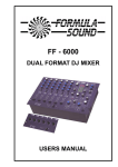
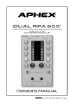
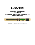
LavryBlack Series
Model MP10
Stereo Microphone Preamplifier
Lavry Engineering, Inc.
P.O. Box 4602
Rolling Bay, WA 98061
http://lavryengineering.com
email: [email protected]
Version 1.0
September 5, 2008
MODEL MP10
The LavryBlack MP10 features:
Ultra-low noise and distortion for transparent sound
Precise matching of channels ideal for stereo recording
High-Low impedance switch to match inputs to Ribbon or Condenser and Dynamic Mic’s
Individually controllable Phantom Power for each channel.
Large wide-range meter -42 to 0 dB
Gain adjustable in 1 dB steps from 20-75 dB
High gain for low output Ribbon microphones
Gain adjustment by digitally controlled analog circuitry for sonic purity
Balanced or unbalanced outputs
CONNECTIONS (Rear Panel)
MICROPHONE INPUTS:
Connect microphones with XLR cables to the Microphone inputs. There is a “hi z/lo z” switch
located between the two input connectors. This allows the input impedance of both channels to
be matched to the type of microphones being used. For example- “lo z” would be used for
Dynamic and Condenser microphones and “hi z” would be used for Ribbon Mic’s. The inputs are
a transformer-free electronically balanced design for accurate and extended bass response with
excellent rejection of unwanted hum and noise.
ANALOG OUTPUTS:
The transformer-free electronically balanced outputs are capable of +24dBu peak level or +18dBu
when set for unbalanced operation. Connect the outputs to balanced inputs using XLR cables.
For unbalanced inputs, use either adapters or adapter cables and set the “unbal/bal” switch to
“Unbal.” The output will be unbalanced “Pin 2 Hot” when the switch is in the “unbal” position.
AC POWER:
The MP10 automatically adjusts to AC power inputs in the range of 90 to 264 Volts AC and line
frequencies between 47 and 63 Hertz. There are no settings to change.
1
OPERATION:
A. Front Panel
The MP10 has three toggle switches on the front panel. There is an individual gain
adjustment for each channel, and a three position toggle switch to enable or disable the
phantom power for each channel. Large numeric digital displays show both the level
during normal operation, and back panel settings on power-up. There is also a wide
range LED level meter to facilitate gain setting and display possible overloads.
B. AC Power Switch and Initialization
The AC power switch is used to turn the power “On” or “Off” on the MP10. When
powered on, the unit initializes for about 10 seconds. During initialization, the gain
displayed by the numeric digital displays start at a minimum setting, then “ramp up” to the
levels that were set before the power was turned “Off.” The numeric displays then switch
to displaying the settings of the rear panel switches while the meter display “scans”
through the segments. Once initialization is complete, the numeric displays revert to the
gain display.
C. Gain
The gain is adjustable for each channel in one dB steps from 20 to 75 dB. Use of a
digitally controlled analog gain circuit allows for precise adjustment and reset-ability,
while maintaining outstanding low-noise and distortion characteristics over a very wide
range of gain. The left channel gain is adjusted using the toggle switch labeled
“Up/Down” to the left of the LEFT GAIN display, and the right channel is adjusted using
the toggle switch labeled “Up/Down” to the right of the RIGHT GAIN display.
The wide gain range accommodates both the vast majority of microphones available and
output levels suitable for both unbalanced “-10” and balanced “+4” level inputs. When the
output switch is set to “unbal,” the maximum output level is reduced by 6 dB from the
maximum level for balanced operation of +24 dBu. Even so, when feeding the output of
the MP10 to an unbalanced “-10” level input, care should be taken to set the gain so that
the peak signal level displayed on the MP10’s meter does not exceed “-6.” This
corresponds to the (approximate) 12 dB difference between the peak level for a “+4dBu”
and “-10dBV” signal. Exceeding this level when feeding a “-10” input may result in
clipping at the input stage of the “-10” device.
D. Meters
The output level is displayed on two 14 segment LED meters covering the range from -46
to 0 dB’s below peak output level. For balanced outputs peak level is +24 dBu, and for
unbalanced outputs peak level is +18 dBu.
E. Phantom Power for Condenser Microphones
The three position momentary toggle switch located between the two numeric GAIN
displays (labeled “phan.”) is used to select +48V Phantom power for each channel,
individually. Clicking the switch once in the up direction will enable or disable the
Phantom power on the left channel, and clicking the switch once in the down direction
toggles the right channel Phantom power on or off. The decimal point in the GAIN display
of the appropriate channel illuminates when the Phantom power is enabled.
F. Impedance Switch
There is a toggle switch labeled “hi z” or “lo z” located on the back panel between the
input and output XLR connectors. The “lo z” position should be used for low impedance
Dynamic or Condenser microphones, and the “hi z” position optimizes the input
impedance for Ribbon microphones. When AC power is applied, the setting of this switch
is displayed in the right GAIN display during initialization.
2
G. Balanced/Unbalanced Switch
The XLR outputs of the MP10 are electronically balanced and should not be connected to
an unbalanced input without first setting the rear panel switch to “unbal.” Doing so will not
cause damage to the amplifiers, but will raise the distortion level of the outputs
significantly. The switch is located between the two sets of XLR connectors and is
labeled “bal” and “unbal.” The peak output level is reduced from +24 dBu to +18dBu
when the switch is set to “unbal.” After AC power is applied, the setting of this switch is
displayed in the left GAIN display during initialization as “ba” for balanced and “Ub” for
unbalanced.
SPECIFICATIONS:
Distortion- Measured at -3dBFS (21dBu) at 1kHz, 10kHz, &20kHz:
Gain Setting 20
Gain Setting 40
Gain Setting 60
Less than 0.00070%dBFS
Less than 0.00090%dBFS
Less than 0.00800%dBFS
Noise- Input referenced noise at Gain Setting 40 with -999dBr input
150 Ohm source
Less than -124dBu (Unweighted)
Less than -127dBu (A-Weighted)
Inputs- Transformer-free electronically balanced Pin 2 “+” XLR inputs with common hi/lo
impedance switch.
Phantom Power- +48 volts Phantom power for condenser microphones, can be enabled or
disabled for each input channel individually using front panel switch.
Outputs- Transformer-free electronically balanced outputs. Rear panel switch for balanced Pin 2
“+” or unbalanced Pin 2 “Hot” operation.
Meter- 14 segment LED meter per channel, displays output signals ranging from -42 to 0dB
below peak output level. Maximum balanced peak output 24dBu, maximum unbalanced peak
output is 18dBu.
Dimensions and Weight- 8”wide x 10.75” deep* x 1.75” high, 4.5 lbs
*depth includes clearance for front and rear panel switches and connectors
AC Power:
Voltage 90-264 VAC, Frequency 47-63Hz, Current 0.1A
Fuse Rating 4A “Fast Blow” *
*Subject to change! Please always check the rating on the fuse and the one printed next to the
fuse holder on the power supply PC board before replacement. Replace the fuse ONLY with a
fuse of the same rating. If you have any questions, contact: [email protected]
ACCESSORIES
Included in box: U.S.A. Power Cord, Warranty Card, This User’s Manual
Optional: LavryBlack Series 19 inch rack-mount kit. This kit is designed to mount two LavryBlack
units side-by-side in a 1U rack space.
3
LIMITED WARRANTY – LAVRYBLACK SERIES MODEL MP10
Subject to the conditions set forth below, for one year after the original purchase date of the
product, Lavry Engineering will repair the product free of charge in the United States in the event
of a defect in materials or workmanship.
Lavry Engineering may exchange new or rebuilt parts for defective parts. Please call the factory
for an RMA number prior to shipment. No product will be accepted for warranty service without
a pre-issued RMA number.
This warranty is extended only to an original purchaser of the product from Lavry Engineering, or
an authorized reseller of Lavry Engineering. Products that are purchased from unauthorized
resellers do not have any warranty coverage. A valid purchase receipt or other valid proof of
purchase will be required before warranty service is provided. This warranty only covers failures
due to defects in materials or workmanship and does not cover damages which occur in shipment
or failures resulting from accident, misuse, line power surges, mishandling, maintenance,
alterations and modifications of the product, or service by an unauthorized service center or
personnel. Lavry Engineering reserves the right to deny warranty service to products that have
been used in rental, service bureau, or similar businesses.
This limited warranty gives you specific legal rights. You may have others which vary from
state/jurisdiction to state/jurisdiction.
LIMITS AND EXCLUSIONS
LAVRY ENGINEERING DOES NOT, BY VIRTUE OF THIS AGREEMENT, OR BY ANY
COURSE OF PERFORMANCE, COURSE OF DEALING, OR USAGE OF TRADE, MAKE
ANY OTHER WARRANTIES, EXPRESS OR IMPLIED, INCLUDING, WITHOUT
LIMITATION, ANY WARRANTY OF MERCHANTABILITY, FITNESS FOR A
PARTICULAR PURPOSE, TITLE OR NONINFRINGEMENT, AND ALL SUCH
WARRANTIES ARE HEREBY EXPRESSLY DISCLAIMED. LAVRY ENGINEERING
EXPRESSLY DISCLAIMS ANY IMPLIED INDEMNITIES. LAVRY ENGINEERING SHALL
NOT BE LIABLE FOR ANY INDIRECT, INCIDENTAL, CONSEQUENTIAL, PUNITIVE,
SPECIAL OR EXEMPLARY LOSSES OR DAMAGES, INCLUDING, WITHOUT
LIMITATION, DAMAGES TO RECORDINGS, TAPES OR DISKS, DAMAGES FOR LOSS
OF BUSINESS PROFITS, BUSINESS INTERRUPTION, LOSS OF BUSINESS
INFORMATION, LOSS OF GOODWILL, COVER, OR OTHER PECUNIARY LOSS,
ARISING OUT OF OR RELATING TO THE USE OF THE PRODUCT, OR ARISING FROM
BREACH OF WARRANTY OR CONTRACT, NEGLIGENCE, OR ANY OTHER LEGAL
THEORY, EVEN IF LAVRY ENGINEERING HAS BEEN ADVISED OF THE POSSIBILITY
OF SUCH LOSSES OR DAMAGES. ANY DAMAGES THAT Lavry ENGINEERING IS
REQUIRED TO PAY FOR ANY PURPOSE WHATSOEVER SHALL NOT EXCEED THE
ORIGINAL COST PAID TO LAVRY ENGINEERING FOR THE APPLICABLE PRODUCT.
BECAUSE SOME STATES/JURISDICTIONS DO NOT ALLOW THE EXCLUSION OR
LIMITATION OF LIABILITY FOR CONSEQUENTIAL OR INCIDENTAL DAMAGES, THE
FOREGOING LIMITATION MAY NOT APPLY TO YOU.
4