1
I N S TA L L AT I O N I N S T R U C T I O N S
L OW- P R O F I L E A N D 2 4 " ( 6 1 0 ) H O O D S
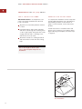
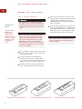
Separate the transition from the rough-in
plate by removing the four shipping screws.
Do not discard the screws; they will be
needed to reinstall the transition to the
rough-in plate.
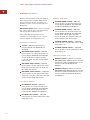
Determine the direction of discharge for
your installation and rotate the back panel
accordingly. The wall hood back panel has
been designed to accommodate a vertical
or horizontal discharge.
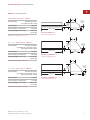
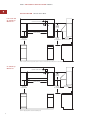
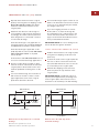
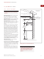
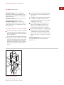
Horizontal discharge requires a wall cut-out.
Refer to the illustrations below. The location
of the cut-out is determined by the installation height of the hood.
If you are installing an in-line or remote
blower, drill a 7/8" (22) hole through the
wood framing for the conduit. Refer to the
in-line and remote blower information on
pages 18–19 and follow installation instructions provided with the blower.
Horizontal discharge is only applicable on
low-profile wall hoods (excluding W302210I
and W362210I) used with a remote blower.
IMPORTANT NOTE: Do not run wiring for the
remote blower through the ductwork.
Horizontal discharge is applicable on 24"
(610) deep wall hoods used with WBLOWER60INT, WBLOWER-120INT or any Wolf
remote blower.
S T E P 4 : R E AT TA C H R O U G H - I N P L AT E
In-line blowers and WBLOWER-90INT are not
for use in horizontal discharge applications.
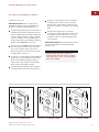
Use the rough-in plate assembly to determine the location of wall studs. Position the
rough-in plate in the desired location and
mark the predrilled mounting holes on the
wall.
For horizontal discharge, the electrical box
will need to be moved so that it is in the
upper right-hand corner of the rough-in
plate when attached to the wall.
Reattach the transition to the rough-in plate
using the four shipping screws removed
previously.
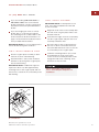
Position the studs on the rough-in plate into
the slots on the hood. Use the hex head
nuts (included with the hood) to secure the
hood assembly to the rough-in plate.
Reinstall the shipping screws removed
previously from the top and back of the
rough-in plate.
IMPORTANT NOTE: If additional support is
required, drill supplementary mounting holes
in the rough-in plate and use these holes to
attach the hood assembly to the wall framing.
Wall Cut-Out Area
Wall Cut-Out Area
17 " (432)
21" (533)
4 1/2" (114)
4 11/16" (119)
5 13/16"
10 1/4"
(148)
(260)
4" (102)
8" (203)
Transition
Centerline
Transition
Centerline
Hood Centerline
Hood Centerline
Wall cut-out for low-profile hoods – horizontal
discharge
Dimensions in parentheses are in
millimeters unless otherwise specified.
Wall cut-out for 24" (610) deep hoods –
horizontal discharge
11