1
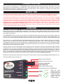
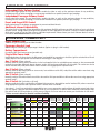
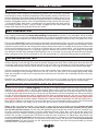
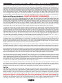
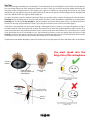
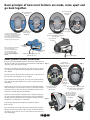
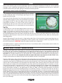
INSTRUCTION
MANUAL and
WARRANTY
Active-PLUS - Kit 200
It is very important that you fully read and understand all of these
instructions before installation and use.
This system is designed for domestic motorcycle use ONLY.
Kit 200 includes:
1003
Active-PLUS (main control unit)
1153
Complete riders headset type A
1179
Rider extension lead
1536
Bike Power Lead
1238
Standard phone lead
1307
Standard music lead
1528
Bike fitting kit
Full Instruction Manual
CONGRATULATIONS
Thank you for choosing Autocom. Your Active-PLUS is designed, built and fully tested to provide you with many years of very
high quality use and performance if installed and used as described in these instructions. Please take time to read and
understand these instructions and feel free to ask your Autocom dealer or call our help line if anything is not perfectly clear
and understood. Telephone: +44 (0)1926 431249 (UK)
SAFETY TIPS
It is very important to properly set up and use these products as designed. Please do not make any modifications or try to use
your system with any non recommended products or in any other way than described. Do not cut or modify your helmets.
It is common sense and the law in some countries that the rider of a vehicle be in control at all times, which includes the ability
to hear other road users warnings. As such the rider should not have the music volume so loud as to prevent this. Safety
should always be your first priority and is ultimately the responsibility of the rider. Mounting the system on the bike is normally
safer than having it on your person. Make sure that the quick release connectors are free to quick release in the event of an
emergency. Do not fix or tape them together. You should only make adjustments while stationary, never while in motion.
Always focus your attention to riding and safety and do not use the system in such a way as to interfere with this. The
added ability to communicate with your passenger and/or other riders can improve safety, so become familiar with using the
system to provide good advice and/or warnings etc.
OVERVIEW
Active-PLUS is normally sold as Kit 200 (solo) which includes a two part rider’s (type A) stereo headset consisting of, a main
headset speaker harness and plug-in boom microphone. You also get a rider’s headset extension lead, the main control box
with a plug-in power lead, standard phone lead, stereo music lead plus a fitting kit that includes various parts to aid most
typical types of installation.
Your Active-PLUS is factory set and so all you need do is install the headset/s and power the main unit with either a PP3 9 volt
battery or the 12 volt power lead included to enjoy. If needed you can easily adjust each headset volume independently, and
in some cases you may need to slightly adjust the VOX control, but once you have done this the rest is hands-free and stunning.
The control box is a specialist high quality audio/communications hub, allowing a rider, to interface with one or two mobile
phones, one or two stereo music sources, GPS and/or radar detector, bike-to-bike radio, and/or a passenger etc simply by
selecting the optional parts to suit your specific needs. It is designed and sold this way to save you costs as to include all possible
parts/options for every potential way it could be used would not be practical or cost effective. Your Autocom dealer should be
able to help you choose what parts you need.
Autocom systems are track tested under extreme speed and noise conditions where they demonstrate highly effective
performance. If your system is not performing as you would expect or as we claim it should then the most likely cause is incorrect
installation or use, in particular microphone and speaker positioning. These instructions have been designed to try to help you
get the most out of your system, but if it does not exceed your expectations then we want to help. You are welcome to visit our
factory any time Monday to Friday 09.00 to 17.00 and Saturday mornings by appointment only. If you cannot get to our factory
then please contact your local dealer or distributor, details available on our website: www.autocom.co.uk
We hope you like this product and enjoy it for many years to come as much as we have enjoyed designing and building it for you.
Tom Beman (MD) Autocom Products Ltd
Aux 3 (normally GPS/radar)
Aux 4 (main bike-to-bike lead)
Passengers headset lead
Riders headset lead
Aux 1 (normally mobile phone)
Aux 2 (normally stereo music/MP3 phone)
2
Passenger
Volume
Low
Rider
Volume
Low
High
High
When the arrow
pointers on the end
of each control face
towards the label it
is set to the standard
settings for use
without earplugs.
ACTIVE-PLUS - MAIN CONTROLS
Independent Rider Volume Control
Colour coded (light green) for easy identification enables the rider to easily set the optimum volume for any conditions,
including use with or without earplugs, or even custom moulded in-ear speaker (monitor type) earplugs.
Independent Passenger Volume Control
Colour coded (olive green) for easy identification enables the rider to easily set the optimum volume for any conditions,
including use with or without earplugs, or even custom moulded in-ear speaker (monitor type) earplugs.
Preset and Forget VOX Control
Neatly tucked away in the battery compartment to prevent accidental knocks.
Additional Internal Adjustability
The Active-PLUS is a high-tech system designed to offer maximum flexibility with many possible variations of use to suit diverse
customer needs. Though factory settings will be optimum for most applications, there are a variety of internal adjustments
which can be made to fine tune the system to individual requirements. Please contact your local Autocom dealer or refer to
our website: www.autocom.co.uk for more details.
ACTIVE-PLUS - CONNECTIVITY
Riders Headset Lead
1200mm long for connecting to the rider’s headset.
Passengers Headset Lead
800mm long for connecting to the passenger’s headset. (Option to plug in a 3rd headset).
Battery Compartment
For optional PP3 9 volt battery power (portable use).
Plug-in Bike Power Lead
Unplug the battery clip then plug-in the bike power lead supplied for connection to the bikes ignition switched fused 12 volt
supply. (Optional two part power lead available for mounting in a tank bag etc).
Aux 1 Socket (3.5mm x 4 pole)
Normally used for mobile phone connection via the lead supplied. Also has switchable power output so that recommended
optional plug and play Bluetooth phone adaptors can be used and powered directly via this socket. This socket can also be
used to interface GPS, radar, bike-to-bike radio or record out using appropriate optional leads.*
Aux 2 Socket (3.5mm x 4 pole)
Normally used for MP3 stereo phone or stereo music, but could be used for GPS, radar, bike-to-bike and/or record out using
appropriate optional leads.*
Aux 3 Socket (3.5mm x 4 pole)
Normally used for GPS and/or radar but could also be used for VOX operated bike-to-bike and/or record out using appropriate
optional leads.*
Aux 4 Socket (60° 5 pole din on fly lead)
Would normally be used for a wide choice of bike-to-bike transceivers, but could be used to interface GPS, radar or record out
using appropriate optional leads. Optional VOX/PTT remote switch is available.
Aux sockets 1, 2 and 3 can optionally be expanded for two or more connections each and have adjustable output levels. Note;
you may require a personal hands-free adaptor block to suit some phones. For bike-to-bike transceivers and interface leads,
plus special leads for GPS and radar etc., please see our full parts list on our website or contact your local dealer for full details.
* Please see matrix below for Functions and Extra Flexibility.
Functions
Active-PLUS
Extra Flexibility
Aux 1
Aux 2
Aux 3
Aux 4
Normally
mobile phone
Normally
stereo music
Normally
GPS/radar
Normally
bike-to-bike
50%
reduction
Auto VOX
transmit
Auto VOX
transmit
Additional
notes for
connection
Can be
used for
option 2
Can be
used for
option 3
Can be
used for
option 4
Can be
used for
option 5
Can be
used for
option 6
Type of
connection
Input to
Rider
lead
Rider speech
Passenger
Passenger speech
lead
Aux 1 Normally phone 1
Affects
Affects
50%
reduction
Affects
100%
cut input
(swt 0 or 100%)
Auto VOX
transmit
Transmit
cut
Auto VOX
transmit
100% cut input
(swt 0 or 100%)
plus cut VOX
transmit
Power out
Switchable
power out for
Bluetooth
adaptor
stereo music/ Affects
Aux 2 Normally
MP3 phone
Aux 3 Normally GPS/radar
Autocom
7 pin
3rd headset
Optional for
1 Bluetooth
via optional
headset adaptor
Y lead
Optional
Bluetooth
phone
adaptor
Autocom
7 pin
Phone 2
GPS/radar
Bike-to-bike
Record out
3.5mm
4 pole
GPS/radar
Bike-to-bike
Record out
3.5mm
4 pole
Affects
3.5mm
4 pole
Bike-to-bike
Aux 4 Normally Bike-to-bike Affects
Adjustable outputs
Optional for
1 Bluetooth
headset adaptor
Power out
GPS/radar
Yes
Yes
Yes
Yes
3
Record out
Autocom
5 pin
60º din
GETTING STARTED
PORTABLE USE
Having read this manual completely and checked any questions with your dealer, you should
now be ready to remove the battery compartment lid and carefully connect a fresh PP3 9 volt
battery to the battery clip and then replace the battery compartment lid, taking care not to trap
any wires. Remember that alkaline type batteries typically last about 5 times longer than cheap
batteries. Rechargeable batteries are not recommended because they normally only have about
1
⁄5 of the capacity. Note; when used as a portable with an internal battery the system remains
automatically switched off unless a type (A) headset is plugged into the riders headset lead
(longest lead). Normally the passenger will carry the system.
BIKE POWERED USE
Having read this manual completely and checked any questions with your dealer you should now be ready to do a pre-installation
test. It is highly recommended that before fully installing the Active-PLUS on your bike, or in a tank bag etc. that you carefully
think it through, as it is easy to do a complete installation only to then find a problem and not know the cause or how to resolve
it. By following these instructions you should find and cure any problems during the installation, and so only need to do it once.
Please note that Active-PLUS is splash resistant; but not designed to be completely sealed so as to allow it to breathe, which helps
to prevent build up of condensation that can develop due to internal heat from the power regulator and main amplifiers. Please
consider its location carefully in order to help prevent excessive water contamination. For example, do not position it where water
will be forced in under pressure, such as in the front of the bikes faring, or under a wheel arch etc. Look for locations say under
the seat near the rear light cluster or in a tank bag or pocket or wherever you are sure it will not get soaking wet. Reasonable
care should also be taken when washing the bike especially if you use a jet wash. You may cover the control box with a bag etc
when washing, but ensure the unit can breathe or you may cause damage if it is allowed to build up excessive condensation.
PRE-INSTALLATION TEST
Lay all the parts out where you think you would like them to go either on the bike (normally under the seat near the rear light
cluster) or perhaps in your tank bag (if you have the optional two part power lead). Think carefully about where the cables will
run trying to avoid areas of potential electrical interference, such as HT leads, coils, spark plugs etc. and voltage regulator (normally
a metal finned box bolted to the bikes frame) and areas of high heat such as engine and exhaust systems and any sharp edges.
Typically if mounting the control unit under the seat the riders lead will come out between the seat and tank (or optionally
from the tank bag), and the passenger lead near to the rear of the seat, often close to the passenger grab handles where
fitted, but remember to watch out for any pressure points which may crush the cables and use packing strips either side of the
cable if required.
Remember this is only a trial fit at this stage. When you think you have it all figured out and have found your preferred
locations, see below for how to temporarily connect the 12 volt lead to a recommended fused ignition switched supply.
CONNECTING THE POWER LEAD TO THE BIKE
Normally you will connect the black (negative) wire directly to the battery negative terminal using the crimped eyelet
supplied as this is the best earth on the bike. Not using the battery earth is the most likely cause for interference issues.
Connect the red (Positive) wire to a recommended, switched ignition, fused supply, such as the positive feed to the tail lights,
or rear brake light switch and solder the joint. Always ask your bike dealer if you are not completely sure. Please note that you
can split the red and black power cable as required and cut them to length but don’t do this until you make the final
connection. Do not connect to the brake light circuit if your bike has ABS braking and/or a brake light failure
warning system (consult your bike supplier/ manufacturer for approval before connecting to any ABS brake light circuit or
bikes that have CANbus). If connection to the brake light circuit is not recommended, please use some other recommended
fused/ignition switched 12 volt supply, such as the rear tail light live feed or any other recommended point.
Always solder joints wherever possible, as this provides a more professional and reliable connection. Do not use quick
connectors like scotch-locks etc. These are nearly always unreliable and most bike manufacturers condemn their use, which
may also affect the bikes warranty. You will notice the supplied fitting kit includes items which will assist in installation (e.g.
tie wraps, insulation amalgamating tape to cover the soldered positive joint, (again don’t use this for the pre-install test) a
crimp type eyelet for connection to battery negative terminal, Velcro to fix the control box and if required also speakers into
helmet). Also consider our optional part 1546 which can help with some installations. For added safety and protection the
system has reverse polarity protection, which means that it reduces the risk of damage if you accidentally wire the power lead
the wrong way around, however, the unit will not function unless wired correctly. The system also has short circuit and thermal
overload protection. This means that the unit will automatically shut down in the event of being overloaded e.g. incorrect
transceiver used or improper connections.
4
FIRST TEST
Please check that the VOX control adjuster in the battery compartment is set per the illustration on page 10. This is a low to
medium VOX setting that should suit most people’s needs on most bikes at most typical speeds and a good place to start with
for this test. Set both rider and passenger volume control knobs all the way clockwise which is the minimum volume level and
a good starting point for use without earplugs in this test. Note you will need to increase the volume/s before using the system
out on the bike and in more noise. Do not use earplugs during this test as they will hide and/or disguise much of what we are
trying to listen for. If you intend using in-ear speaker plugs (monitor type earplugs via our optional adaptor extension lead
part 1187) then do so for this test, as monitor earplugs are brutishly honest at letting you hear even the slightest of noises and
so this will help you to fine tune the installation. Note; that you may have to slightly adjust the volume up or down to suit
your speaker plugs.
With the main unit now in your preferred location and ready to power, assemble the headset by plugging in the boom
microphone and then connect this to the headset extension lead and plug this into the rider’s lead of the main control box. If
you have opted for the optional passenger headset then please also plug this in now and get them to assist you with this test.
Before staring the engine make sure that no parts or leads can fall onto a hot exhaust etc. Start the engine in a well
ventilated area and hold the speakers directly over your ears with light pressure and listen for any electrical interference such
as a whining/whistling sound relative to engine RPM which is most likely due alternator or regulator noise, or a continual tick,
tick, tick… relative to engine RPM which is due to HT ignition coils, leads or plugs noise. If you hear any such noises then move
various parts about one at a time while listening with the engine running to find out which part is suffering from noise and
where to move it to so that it becomes clean.
If you are planning on plugging in any other devices such as bike to bike, GPS and/or radar detector etc or one of our special
on-bike music interface leads, now is the best time to connect these up per their instructions and do a pre install test with each
part to make sure the sound is clean and clear with the engine running at various RPM. If you do this one item at a time
and check for any interference you will hear if any noise is introduced and which device/lead is the cause and so can relocate
that part/lead so that the interference goes away. When you are sure that the locations you have chosen for each part and
their leads are clear of electrical interference and risk of heat damage etc you are then ready to continue.
Note the microphones are automatically switched of until you speak, and when you do the side-tone lets you hear your own
voice through your own speakers which helps you to speak at the correct level when out on the bike in noise. When you stop
speaking the VOX will automatically 100% cut the microphone/s and return any music played through Aux 2 back to its
original level.
If while holding the speakers over your ears you speak into the beige side of the microphone and gently move it about with
it just touching your lips you will discover a LOUD SPOT that produces the highest level of sound. Please note how just a few
millimetres (1⁄8”) movement can grossly effect the level of your speech and so your ability to operate the VOX. You must ignore
the fact that you can hear yourself through you own speakers and continue to project your voice through the microphone as
if to someone 15 feet (5 metres) away. It can help if you pucker your lips as if kissing the microphone and/or turn the volume
down if it is too loud.
If you do not use the loud spot correctly the level of your voice will be greatly reduced and so you will struggle to operate the
VOX or hear at high speeds, especially when using high attenuation earplugs. It is therefore very important that you and
your passenger learn about and use this loud spot as the system is tuned to it. With a little practice and especially
when you go out on the bike and the helmet noise increases it all becomes much more natural and you will soon be able to
move the microphone away slightly and still reliably operate the VOX, but to start with and to help get you through this initial
learning curve please bear with us as it will help you to understand and use the system as designed, resulting in superior
communications and long term enjoyment.
It is a natural reaction whenever the VOX breaks up the speech to be tempted to turn the VOX controller anti-clockwise so
that it makes it easier to speak to, but you must not do this, instead find and use the microphone loud spot and project your
voice positively through it which will produce far more energy into the system and so make it easier to operate the VOX
reliably, especially when you go out on the bike and the increased helmet noise makes you want to speak louder. If required
try turning the volume control as low as you can and still hear, as with a lower volume setting you will naturally speak louder.
When you are happy that your system is performing cleanly and clearly even with the VOX open and microphones on without
electrical interference you are ready to continue.
Note that you may notice a slight amount of noise coming through the system when the VOX turns the microphones on, but
this is normal so long as it is not the alternator whining or HT ticking noise previously described.
5
MAIN CONTROL UNIT FINAL INSTALLATION
Where you route the cables along the frame of the bike etc, secure them as required using tie wraps. Care should be taken to ensure
that the cables cannot fall into the chain, wheel or foul the steering etc, or be trapped or crushed by the seat or body panels. If
required use some hard packing strips either side of the cables to prevent damaging the cables at pressure points such as where the
cables come from under the seat between the tank and body panels etc, if required bond the packing strips in place but only after
you are sure of the final location. Avoid any sharp angles or edges, which may damage or cut the cables. Pay particular attention to
the seat locking mechanism, which, if fouled could cause problems with removing the seat. When using tie wraps please be careful
not to over tighten them, taking care to avoid brake-lines, breathers, overflow pipes etc. and when you cut the surplus off any tie
wraps remember to cut short and square so that it reduces any sharp edges that may scratch you when servicing or washing the bike.
Before installing your headsests - DO NOT CUT OR MODIFY YOUR HELMETS
Plug in boom part 1109 (supplied as part of the complete headset) is our most universal boom designed to fit most full face,
flip front and open face helmets, although open face and some flip front helmets will require the optional open face
conversion kit (part 1198) to prevent direct wind blast. The headset is not designed to work with 1⁄2 helmets (Chip style) which
normally require a longer boom and perhaps some additional padding to mount the speakers over your ears. Replacement
consumable foam speaker covers (part 1197) and replacement consumable microphone coverings (part 1214) are available
from your dealer. Part 1110 is similar to our part 1109 but is slightly longer (35mm or about 13⁄8”) for very large heads/open
face helmets. Part 1111 is a short boom designed to velcro into the helmets chin bar (front fit). This can be useful in some flip
front helmets and most full face helmets, but not normally suitable for open face helmets due to lack of chin bar.
It is important to know that if not used correctly you will be losing much of the superior quality and performance that Autocom
headsets have to offer and what makes them by far the very best. It may take several attempts to get it right but when you do
it will pay dividends in sound quality, performance and comfort. In order to fully understand the full potential of your Autocom
system you need to hear it at its very best and only then will this give you a benchmark to work to during installation and
adjustment. Make sure that the rider and passenger volume controls are set to their mid positions, such that the pointers on the
end of each knob face the label, and do not use earplugs for this test. Note; if you are going to use a passenger headset then
it is a good idea to assemble this and plug it in to the passenger lead and to get them to assist you with this test, as when it
comes to checking their speaker positioning in their helmet only they can do this properly to suit them.
If possible try to create as much background noise as you possibly can, i.e. you may get someone to rev your bike engine if outside,
or perhaps turn on a noisy vacuum cleaner etc if in the house. If possible play one of your favourite pieces of music which has
good quality rich sounding bass etc through the system, via the stereo music lead supplied plugged into Aux socket 2. Adjust the
music to a comfortable level using the volume control on the music system making sure that you plug into the music systems
headset socket and not the line out socket or the volume control will not work.
Carefully move the speakers about over your ears so that the speaker centres are directly over the centres of each ear hole
(note that each speaker is offset in its plastic housing and has a three pointed star under the foam covering so that you can feel
where the centre of the speaker is, to help you find the speaker centre relative to your ear holes when fitted in the helmet.)
Apply slight pressure to the back of the speakers over your ears and the music playing through the system should almost completely
drown out most if not all of the noise in the background. When you have adjusted the speaker positioning so that the music quality
is at its very best and you can hear the least amount of background noise coming through, you have found the best possible speaker
position and sound quality and so you now know what to aim for when installing your speakers into your helmet.
You will notice that moving the speakers just 6mm (1⁄4”) away from the ears or out of alignment can easily halve the volume
and reduce the sound quality by letting in considerable external background noise, which will spoil the full potential of sound
quality and performance, especially at higher speeds when out on the bike and the helmet noise becomes far more powerful.
Correct speaker positioning is therefore essential and you will hear this during this test. It is also beneficial to speak through
the system so that you get a measure for the speech quality and level when the speaker are correctly positioned, but in order
to do this you first need to find, understand and use the microphone loud spot.
Listen to both music and speech carefully and try to remember the audio levels and in particular the quality of rich bass in the
music, because after installation in your helmet/s you need to assess if the sound level and quality are as good as before,
because if not you need to fine tune the speaker and/or microphone positioning until it is. Please use the same piece of music
through the system and same level of exterior noise during both pre-installation and after installation tests.
Top Tips
This may seem a strange way of evaluating and setting up the system but it really works and although your first helmet may
take a little longer you will get it right and then all further headset installations should be much easier and quicker due to
getting through this important learning curve. Do both the pre-installation test and the final test after helmet installation
without earplugs so that you can hear the vast difference it makes in having your microphone and speakers positioned
correctly. If you try this while using earplugs they will disguise much of what you are trying to hear, understand and achieve.
Avoid pressure directly to the front and back covers of the microphones as this could cause damage. The
microphone is floating in an acoustically dampening material to help prevent any helmet vibration being transmitted through
the boom to the microphone as part of the noise cancelling measures. To move or adjust the microphone please hold it by the
outer edges or rubber neck, making sure that the beige side of the fabric sits flat against and central to your lips.
6
HEADSET INSTALLATION
There are far too many different helmets to be able to fully describe every possible installation and so these instructions are
designed as a basic guide only. Please see your local Autocom dealer or our website www.autocom.co.uk for more detailed
specific helmet installations. Please note; helmets that have straps that go directly over your ears do not lend themselves for
a good headset installation, as the speakers have to sit either on top or behind the straps which can make them uncomfortable
or reduce sound quality. This is beyond our control and if our speakers do not fit then nor will others. It is a good idea to
remember this next time you choose a helmet. You can overcome this problem using optional in-ear speaker plugs that can
replace the standard over the ear type speakers. Our optional part 1187 interfaces many in-ear speaker plugs to the ActivePLUS. Some helmets do not lend themselves to be installed as we have suggested and may require alternative methods, so
please take some time to consider these basic principles and your helmet design before installation. If you are unsure then
please contact your supplier or Autocom for help and advice.
Please take a moment to study the helmet illustrations on the front cover and also those on page 9 and then your own helmet/s
to see if you can establish any similarities that may help you with installation ideas. There are two main types of full face
helmet designs, one is a one part chin and cheek pad design, per the illustration shown on the top right of page 9, the other
type is a three part chin/cheek pad design per the illustration shown at the top left of page 9. Most full face helmets do not
have the cheek pads glued in and are just a compression fit, which makes them much easier to remove (although some are
quite tight). Put the helmet on and work out exactly where the centre of each ear hole is relative to the straps or any seams
etc. in the lining, and also while doing this try to find and mark the exact location of the centre of your lips inside the chin
pad with the helmet sat in its natural position. When you have established these positions within the helmet you are then
ready to start the headset installation/s
Decide which side of the helmet you would prefer the lead to hang from and then release that side’s check pad so as to allow
you fit the boom and main speaker harness behind it, such that the boom comes up from behind the check pad and into the
visor area, so that it can be bent down (from between the outer shell and check pad) in front of your mouth, per the
illustrations. If required tape the boom and also the main harness down lead to the back of the cheek pad or preferably to
the inside of the outer shell of the helmet.
Most helmets have pockets (indentations) in the lining by your ears, which let your ears fold back after they are folded over
while putting the helmet on. Sometimes the fabric covering these pockets is glued back to the cheek pad forming a visible
pocket, and other times the fabric is just stretched over the foam pocket and is not glued back. If the helmet has deep pockets
and the fabric is glued back you may need to fit padding behind the speakers (like our optional foam speaker pads part 1203
which are about 6mm or 1⁄4” and part 1204 which are about 12mm or 1⁄2”) these foam speaker pads have velcro fitted so that
you can velcro the speakers to them.
If the fabric is not glued back forming a visible pocket then it is easiest to just velcro the speakers on top of the fabric which
can often work quite well in some helmets, but is more likely to cause your ears to fold over when putting the helmet on and
so most people prefer a more professional installation where the speakers are set behind the fabric but on top of the
foam/polystyrene behind. If you have time and can install the speakers behind the fabric like this it makes for a much more
professional semi permanent fitment which is normally much more comfortable and this is how we would normally try to
install the headset/s for you if you brought them to us.
7
Top Tips
After first installing the headset/s into the helmet/s it is often beneficial to use something like a silk balaclava to help prevent
your ears being folded over while putting the helmet on and off until you have fine tuned the speaker positioning for
maximum comfort and performance. If for example your right ear is folded over after putting the helmet on you should
immediately use your right hand to pull the right hand strap so that you can get your left hand fingers up into the right hand
side of the helmet to flick your right ear back straight etc.
In order to be able to place the speakers behind the fabric you normally need to remove the cheek pads from the helmet.
Carefully remove the cheek pads to reveal the back where the fabric is either glued back or taped back to the polystyrene.
Carefully peel the fabric back just enough to slide the speakers into place (normally about level or just below the level of
the hole for the strap and just behind the strap). Try to copy the illustrations on the front cover and/or page 9.
If the fabric is not glued back into the pockets forming a visible pocket then it is easiest to just velcro the speakers on top of
the fabric which can often work quite well, however if you have time to install the speakers behind the fabric it makes for a
much more professional semi permanent fitment which is normally much more comfortable. (This is normally how we would
install the headset for you if you brought it to us). Put the helmet on and try to work out exactly where the centre of each
ear hole is relative to the strap or any seams etc in the lining, and while doing this also try to find and mark the exact location
of the centre of your lips inside the chin pad with the helmet sat in its natural position.
If required use some double sided tape or some of the velcro in the kit to help anchor the boom and down lead in to the helmet.
You must speak into the
beige side of the microphone
Centre of
speaker
Centre of
ear hole
Note that wire
normally comes out
towards back
Centre of ear
hole
Avoid speaker
near top of ear
Centre of ear
hole
Centre of
speaker
8
Basic principle of how most helmets are made, come apart and
go back together.
View from underside
of Shoei type
helmet
View from underside
of Arai type
helmet
The fabric is either taped or
elasticated over the polystyrene and
so it is easy to install the speakers
behind the lining. Note that the
wire should come out of the speaker
towards the back of the helmet.
When replacing the cheek pads,
trap the boom between
the outer shell and the inner
cheek pads plastic tongue
if it has one. Tape or glue if
required. Do not modify the
helmet.
Remove
straps and
lift out complete
Remove
straps and lift out
each cheek pad
individually
Peel back tape and lining, Slide
Speaker inside pushing it right up to
the strap hole
Boom and Mic
assembly
Boom and Mic
assembly
Return Assembly as
removed
Return Assembly as
removed
Trap Boom (or tape) between cheek
pad and outer shell
Tape to hold in place
BMW System 4 Helmet Installation
Remove neck collar by pulling the back of the collar away from the helmet and
slide both side guides out from retaining locators. Detach Velcro flaps (marked Step 1
‘A’ below) to expose the polystyrene ear cups.
Thread boom (microphone first) under the chin strap but over the opened
Velcro flaps (A). Locate speakers just below the polystyrene ear indents under the
Velcro flaps (B).
Viewed from
underside of Helmet
with chin bar open
and neck collar
removed
Step 2
Neatly tuck speaker cable under lining around the back of the helmet and
below the neck collar retaining groove, out of sight (C).
Position headset down lead along the outer edge of the helmet under the
Velcro flap. This may require addition Velcro to ensure security. Close the Velcro
flaps and tidy.
Push the thin section of boom into the joint between the skull and cheek lining,
under the chin strap. Locate the boom across the top of left hand cheek pad
forming it to follow it’s contours. Hold boom down firmly and secure in place
with Velcro or a suitable sticky backed material (D).
Fit speakers in the ear
pockets under the
velcroed flaps.
Form boom so that microphone is situated in-front of and just touching your
lips in the centre. Check that down lead and boom are well secured and wires
are tidily tucked away. Carefully check the opening and closing of the front of
Step 3
the helmet does not snag the boom or down lead.
Test the headset and reposition microphone and speakers if required.
Refit neck collar.
Please note that due to the design of this helmet, positioning of the speakers is
limited and as such it may not be possible to position the speakers directly in
line with your ears. If this is the case one cannot expect the sound to be good
when using earplugs.
Pass
boom
assembly
under flap
in direction of
arrow
Tuck speaker wire away around the
back of the lining underneath the
groove for the neck collar
The boom is tucked
tight into groove above
the cheek pad and
under the chinstrap
mounting
Align boom across
the top of the
cheek pad
D
9
VOX
VOX or voice activation, gives you several advantages. Apart from turning the microphones off when you are not speaking,
ensuring no noise is picked up and amplified to the users ears, the VOX can automatically mute the music or make your
transceiver transmit when you speak, giving you hands free and safer operation.
SETTING THE VOX CONTROL
If you are going to be using a passenger headset then you should do
so when setting the VOX, as the passenger typically get far more
helmet noise that the rider.
If you start with the VOX control set to the centre position per the
illustration below and go for a ride to see if the helmet noise at speed
false triggers the VOX. If it does then slightly turn the VOX control
knob clockwise say about 1⁄8 of a turn at a time and try it again and
keep doing this until you have set the VOX such that helmet noise
does not accidentally turn it on at speed when you are not speaking.
Top Tip
It is a good idea to set the VOX about 20mph (32kmh) faster than you
would normally travel so that head winds do not cause it to false
trigger. If your helmet has chin bar vents that allow air to blow
straight through onto or near the back of the microphone area then
this should be blocked off from the inside of the chin bar such that (1) you do not get direct wind blast to the back of the
microphone/s and (2) because in most cases this also helps to get more air up into the visor area, which can often help with
demisting problems.
Incorrect VOX setting will cause the music to keep muting and/or bike to bike transceiver to keep transmitting when not
speaking and this would prevent you from being able to receive and this is why a correctly set VOX is very important and why
you must find and use the LOUD SPOT rather than reduce the VOX level to compensate.
A wind/draft excluder is sometimes fitted under the chin bar of some helmets and this can help reduce excessive wind noise
thus allowing for a lower VOX setting.
USING BIKE-TO-BIKE TRANSCEIVERS
Although it seems simple, and it can be, there are a few tricks to help you get the most out of you transceivers, which should
be set up as per their instructions including being fully charged and connected properly via the appropriate interface lead.
Ensure that the radios are not in VOX mode. Practice some radio discipline - turn the radios on, plug one of the radios into the
Active-PLUS unit and get someone else to use the second radio as a hand held unit and talk back to you using the push-totalk button on the side of the radio. Remember the radio’s are simplex which means only one person can talk at a time. Ideally
having a third transceiver can help by letting you hear any problems and who is causing them.
Autocom’s VOX system is almost instant and between rider and passenger if you said “don’t turn left” you would both hear
“don’t turn left” without clipping, but it should be noted that when communicating between bike-to-bike using a simplex
transceivers you will get a short delay before the transceiver transmits because it has to wake up from standby or receive mode
and only after it has transmitted its anti interference tone code and the other transceiver receives this and verifies the tone
code is correct can it switch on the received speech for you to hear, and this can take typically about 1⁄2 a second or so. As such,
if you said “don’t turn left” it may come over as “urn left”. It is therefore good practise to use a trigger word at the beginning
of each conversation such as “ok, don’t turn left” or “ok, when you get to the lights don’t turn left”, so that the important
part of the message is received. It is also good practice to always say “over” at the end of each conversation so that other
people know that you have finished speaking and they can speak back. However, it should also be noted that the VOX is
deliberately designed to hold on for a short period when you stop speaking and this is to allow for any short pauses during
normal speech so that it does not keep tripping off when your are speaking. The delay is a compromise between being too
short and so causing clipping when speaking, and turning off as quickly as possible so that when you have finished speaking
others can speak back with minimum delay time. The amount of your voice energy will slightly effect the delay time after you
finish speaking so if your last work is loud it will hold the VOX on slightly longer than if your last work is soft and you can use
this to your advantage.
10
TROUBLESHOOTING GUIDE
Speech volume is too quiet.
G Ensure that you are talking into the beige side of the microphone and it is positioned in the loud spot. See page 5 for
more details.
G Adjust the riders/passengers volume control to increase volume level.
G Ensure speakers are positioned correctly. See page 8 for more details.
Phone/GPS/radar/transceiver volume is too quiet.
G Adjust volume level on audio device such as phone/GPS.
G Ensure speakers are positioned correctly. See page 8 and 9 for more details.
G Adjust the rider’s and/or passenger’s volume control to increase volume level.
Music volume is too quiet.
G Adjust volume level on audio device.
G Adjust the rider’s and/or passenger’s volume control to increase volume level.
G Ensure speakers are positioned correctly. See page 8 for more details.
Music mutes 50% even when I don’t speak.
G Turn the VOX control clockwise
Phone will not auto answer.
G Ensure your phone has this facility.
G Ensure that you have connected the adaptor block properly (if needed).
G Check that the phone is set to auto-answer whilst in headset mode (hands-free).
G Try connecting the adaptor to the phone followed by plugging the lead in.
Problems with bike-to-bike radios
G Ensure that you take turns to speak and that you leave 2 seconds between transmissions. See page 10 for hints and tips.
G Ensure both transceivers are on the same channel and sub-tone.
G Check that the connections on the radio are secure.
G Adjust volume level on transceiver.
G Ensure the microphone is positioned correctly and that you are using the loud spot see page 5.
G If using a press to talk (PTT) check the switch position.
G Ensure that the PTT switch position is central when powering up the system.
Interference whilst the engine is running.
G If you are bike powering an audio device, check that you are using an isolated lead to interface it to the system.
G Unplug all accessories and see if the noise is still audible. If the noise has gone, plug one lead in at a time until the noise
returns. You now know which lead is picking up the noise. It will either need re-routing or it is an incorrect lead.
If you need more help or advice please contact your local Autocom supplier.
11
Warranty
If your supplier has not given advice or demonstration on how to set
up or use our products, please check with them before sending any
goods back for warranty.
All Autocom products are warranted for a period of 12 months from the date of
original purchase, to the original purchaser, from an authorised Autocom retailer. This
warranty covers faulty materials or workmanship, subject to the goods being used only as
stated, and only for the purpose as described in the instruction manuals.
No manufacturer's warranty applies to the goods where they are used for any other purpose or in
any other way than is explained in the instructions. Nor where the goods have been subjected to
misuse, neglect or accidental damage, or used with any other vendor’s products, including incorrect
mechanical or electrical installation, or where the goods have been repaired, modified or altered, without
the manufacturer’s written authorisation.
The manufacturer's warranty is limited to the goods being returned pre paid to the manufacturer's factory,
with the original packaging and the original proof of purchase date. The goods must be intact for our
examination.
Where goods are accepted by the manufacturer, under the terms of the warranty, they will be repaired free of
charge or replaced (at the option of the manufacturer). Where the goods are returned as faulty and are found
not to be, a charge will be payable to cover costs of inspection, testing, packing and return postage.
This warranty does not cover any consumable items such as batteries, replaceable hygiene foam coverings
for speakers and microphones, or any other items that are described within the instruction manuals as being
a consumable.
The manufacturer's warranty does not affect your statutory rights.
PLEASE CONTACT YOUR SUPPLIER OR AUTOCOM FOR ANY FURTHER HELP OR INFORMATION.
www.autocom.co.uk
We service what we make
For details of Autocom’s International distributors and support network, please see our website
UK Manufacturer and Distributor
Autocom Products Ltd.
Unit 4, Tachbrook Link, Tachbrook Park Drive, Warwick CV34 6RH England.
Telephone: +44 (0)1926 431249 (10 lines) Fax: +44 (0)1926 431250
Email: [email protected] Website: www.autocom.co.uk