1
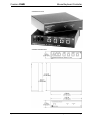
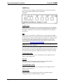
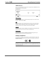
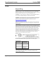
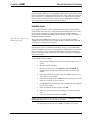
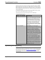
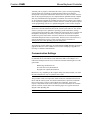
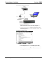
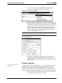
Crestron CNMK
Mouse/Keyboard Controller
Operations Guide
This document was prepared and written by the Technical Documentation department at:
Crestron Electronics, Inc.
15 Volvo Drive
Rockleigh, NJ 07647
1-888-CRESTRON
All brand names, product names and trademarks are the property of their respective owners.
©2005 Crestron Electronics, Inc.
Crestron CNMK
Mouse/Keyboard Controller
Contents
Mouse/Keyboard Controller: CNMK
1
Introduction ............................................................................................................................... 1
Features and Functions ................................................................................................ 1
Specifications .............................................................................................................. 2
Physical Description.................................................................................................... 2
Industry Compliance ................................................................................................... 5
Setup .......................................................................................................................................... 6
Network Wiring........................................................................................................... 6
Identity Code ............................................................................................................... 7
Hardware Hookup ....................................................................................................... 8
Power Up Sequence..................................................................................................... 9
Programming Software .............................................................................................................. 9
Earliest Version Software Requirements for the PC ................................................... 9
Programming with SIMPL Windows .......................................................................... 9
Uploading and Upgrading........................................................................................................ 12
Communication Settings ........................................................................................... 13
Uploading a SIMPL Windows Program.................................................................... 15
Firmware Upgrade..................................................................................................... 16
Problem Solving ...................................................................................................................... 18
Troubleshooting......................................................................................................... 18
Further Inquiries ........................................................................................................ 18
Future Updates .......................................................................................................... 18
Appendix: AT Scan Codes ...................................................................................................... 19
Return and Warranty Policies .................................................................................................. 21
Merchandise Returns / Repair Service ...................................................................... 21
CRESTRON Limited Warranty................................................................................. 21
Operations Guide – DOC. 5699A
Contents • i
Crestron CNMK
Mouse/Keyboard Controller
Mouse/Keyboard Controller:
CNMK
Introduction
Features and Functions
The Crestron® Mouse/Keyboard Controller, CNMK, with the supplied Y-mouse
Adapter, is an expansion module that provides a USB interface between the Crestron
network control system (Cresnet®) and a Windows®-based PC. The CNMK allows
mouse and keyboard commands to be executed from the control system and sent to
the computer to control software applications.
The CNMK is also available in an international version, the CNMKI. All features are
identical with the exception of the international AC power requirements.
The PW-1205 power supply (120 VAC) is provided with the CNMK; the PW-1210
power supply (220 VAC) is provided with the CNMKI. Both units may be powered
via Cresnet (with no power supply connected).
Throughout this guide, all references to CNMK apply to both versions except where
noted.
Functional Summary
Operations Guide – DOC. 5699A
•
Provides a USB interface between the Cresnet system and a Windows®
based PC
•
Mouse and keyboard commands executed from the control system are
sent to the PC to control software applications
•
Enables display of QWERTY keyboard equivalent on any large Crestron
touchpanel
•
Can be rack mounted using the optional ST-RMK rack mount kit
•
Can be powered via Cresnet or provided power supply
•
Two NET ports allow unit to be daisy-chained with other Cresnet units
Mouse/Keyboard Controller: CNMK • 1
Mouse/Keyboard Controller
Crestron CNMK
Using the CNMK, it is possible to display the equivalent of a QWERTY keyboard on
any large Crestron touchpanel to allow manual real-time text entry directly to a PC
from the touchpanel screen. Select keyboard commands can be assigned to buttons
on any Crestron handheld remote to control computer-based slide presentations.
Macros can be easily programmed to execute a string of commands.
The CNMK includes pass-through connectors to enable the simultaneous connection
of a standard or wireless PS/2 keyboard and mouse. However, since not all PS/2-type
keyboards and mice are fully plug-and-play compatible with all PCs, Crestron
recommends the use of the supplied Y-mouse Adapter. (Refer to the “Simplified
Configuration Diagram” on page 8.)
Specifications
The table below provides a summary of specifications for the CNMK.
Specifications of the CNMK
SPECIFICATION
DETAILS
Cresnet Power Usage
3 Watts (0.125 Amps @ 24 VDC)
Default Net ID
28
Control System Update Files
1, 2, 3
2-Series Control System
Version 2.004.CUZ or later
CNMSX-AV/PRO
Version 5.14.02X.UPZ or later
CNRACKX/-DP
Version 5.14.02W.UPZ or later
CEN/CN-TVAV
Version 5.12.63V.UPZ or later
ST-CP
Version 4.02.4S.UPZ or later
CNMK Firmware
CNMKv2.0.upg or later
Environmental Temperature
32° to 113°F (0° to 45°C)
Humidity
10% to 90% RH (non-condensing)
Overall Dimensions
Height:
Width:
Depth:
1.70 in (4.32 cm)
7.07 in (17.95 cm)
6.33 in (16.06 cm)
Weight
2.0 lb (0.90 kg)
The latest versions can be obtained from the Crestron website. Refer to NOTE after last footnote.
Crestron 2-Series control systems include the AV2 and PRO2. Consult the latest Crestron Product
Catalog for a complete list of 2-Series control systems.
3.
Filenames for CNX and ST-CP update files have a UPZ extension. Files on the website may be .zip or
self-extracting .exe files containing the .cuz or .upz file. All can be obtained from the Downloads section
of the Crestron website. To avoid program problems, make sure you are using the update file with the
correct suffix letter (e.g., S, V, W, X).
1.
2.
NOTE: Crestron software and any files on the website are for Authorized Crestron
dealers and Crestron Authorized Independent Programmers (CAIP) only. New users may
be required to register to obtain access to certain areas of the site (including the FTP site).
Physical Description
The CNMK is housed in a black enclosure with labeling on the front and rear panels.
Four LEDs on the front of the unit indicate the unit’s status. All the connections are
made on the back of the unit. Refer to the following physical views shown after this
paragraph. There are four rubber feet on the base of the unit for stability and to
prevent slippage.
2 • Mouse/Keyboard Controller: CNMK
Operations Guide - DOC. 5699A
Crestron CNMK
Mouse/Keyboard Controller
CNMK Physical Views
CNMK Overall Dimensions
Operations Guide – DOC. 5699A
Mouse/Keyboard Controller: CNMK • 3
Mouse/Keyboard Controller
Crestron CNMK
CNMK Ports
All connections to the CNMK are made through the ports on the back of the unit.
Refer to the illustration and descriptions, which follow.
CNMK Ports
12 VDC .5 A
This DC power socket connector is used to supply external power via the supplied
500 mA power pack (1000 mA power pack for CNMKI configuration). If power for
the CNMK is supplied by the Cresnet system, the supplied power pack should be
disconnected.
NET
These two 6-pin, 6-position RJ-11 modular jacks are used to connect the CNMK
module to the Cresnet system. Typically, power is provided via the NET connection;
the supplied power pack need not be attached. Two NET ports are available so that
network units can be daisy-chained together. Review the latest revision of the
Network Modular Cable Requirements (Doc. 5682) which is available from the
Crestron website (http://www.crestron.com/manuals).
NOTE: Most 4-conductor phone cables are wired in a crisscross fashion and are not
compatible with Crestron equipment.
If the power pack is attached when the CNMK is part of the Cresnet system, power is
drawn from the power pack. The CNMK does not load the network power, but the
network power remains chained for additional network devices that are connected.
TO MOUSE PORT
This PS/2 connector connects to one of the PS/2 ports on the supplied Y-mouse
Adapter via the supplied cable.
MOUSE
This PS/2 connector is not typically used. Crestron recommends using the
configuration shown in “Hardware Hookup” on page 8.
TO KEYBOARD PORT
This PS/2 connector connects to one of the PS/2 ports on the supplied Y-mouse
Adapter via the supplied cable.
KEYBOARD
This PS/2 connector is not typically used. Crestron recommends using the
configuration shown in “Hardware Hookup” on page 8.
4 • Mouse/Keyboard Controller: CNMK
Operations Guide - DOC. 5699A
Crestron CNMK
Mouse/Keyboard Controller
CNMK Indicators
There are four LED indicators located on the front panel of the CNMK. Refer to the
following illustration and descriptions.
CNMK Indicators
PWR (Power)
This LED illuminates when 12 volts (from the power pack) or 24 volts DC (from
network) is supplied to the CNMK.
NET
This LED illuminates when communication between the Cresnet system and the
CNMK is established. Illumination indicates that the SIMPL program currently
loaded has a network device defined at the same ID as the CNMK.
MOUSE
This LED illuminates when the CNMK receives inputs that are translated from the
Cresnet system as mouse activity (movement or button presses).
KEYBOARD
This LED illuminates when the CNMK senses bidirectional signal activity as
translated from the Cresnet system as keyboard activity.
Industry Compliance
As of the date of manufacture, this unit has been tested and found to comply with
specifications for CE marking and standards per EMC and Radiocommunications
Compliance Labelling.
NOTE: This device complies with part 15 of the FCC rules. Operation is subject to
the following two conditions: (1) this device may not cause harmful interference, and
(2) this device must accept any interference received, including interference that may
cause undesired operation.
Operations Guide – DOC. 5699A
Mouse/Keyboard Controller: CNMK • 5
Mouse/Keyboard Controller
Crestron CNMK
Setup
Network Wiring
CAUTION: In order to ensure optimum performance over the full range of your
installation topology, Crestron Certified Wire, and only Crestron Certified Wire,
should be used. Failure to do so may incur additional charges if support is required to
identify performance deficiencies as a result of using improper wire.
CAUTION: Use only Crestron power supplies for Crestron equipment. Failure to
do so could cause equipment damage or void the Crestron warranty.
CAUTION: Provide sufficient power to the system. Insufficient power can lead to
unpredictable results or damage to the equipment. Please use the Crestron Power
Calculator to help calculate how much power is needed for the system
(http://www.crestron.com/calculators).
NOTE: When installing network wiring, refer to the latest revision of the wiring
diagram(s) appropriate for your specific system configuration, available from the
Crestron website.
When calculating the wire gauge for a particular Cresnet run, the length of the run
and the Cresnet power usage of each network unit to be connected must be taken into
consideration. If Cresnet units are to be daisy-chained on the run, the Cresnet power
usage of each unit to be daisy-chained must be added together to determine the
Cresnet power usage of the entire chain. If the unit is a home-run from a Crestron
system power supply network port, the Cresnet power usage of that unit is the
Cresnet power usage of the entire run. The length of the run in feet and the Cresnet
power usage of the run should be used in the following resistance equation to
calculate the value on the right side of the equation.
Resistance Equation
The required wire gauge should be chosen such that the resistance value is less than
the value calculated in the resistance equation. Refer to the following table.
Wire Gauge Values
RESISTANCE
WIRE GAUGE
4
16
6
18
10
20
15
22
13
Doubled CAT5
8.7
Tripled CAT5
NOTE: All Cresnet wiring must consist of two twisted pairs. One twisted pair is the
+24V conductor and the GND conductor, and the other twisted pair is the Y
conductor and the Z conductor.
6 • Mouse/Keyboard Controller: CNMK
Operations Guide - DOC. 5699A
Crestron CNMK
Mouse/Keyboard Controller
NOTE: When daisy-chaining Cresnet units, strip the ends of the wires carefully to
avoid nicking the conductors. Twist together the ends of the wires that share a pin on
the network connector, and tin the twisted connection. Apply solder only to the ends
of the twisted wires. Avoid tinning too far up the wires or the end becomes brittle.
Insert the tinned connection into the Cresnet connector and tighten the retaining
screw. Repeat the procedure for the other three conductors.
Identity Code
Every equipment and user interface within the network requires a unique identity
code (Net ID). These codes are two-digit hexadecimal numbers from 03 to FE. The
Net ID of each unit must match an ID code specified in the SIMPL Windows
program. Refer to “Setting the Net ID in Device Settings” on page 11 for details of
the SIMPL Windows procedure.
Refer to the note on page 13 for a
definition of Viewport.
The Net ID of the CNMK has been factory set to 28. The Net IDs of multiple
CNMKs in the same system must be unique. Net IDs are changed from a personal
computer (PC) via the Crestron Viewport.
NOTE: For detailed information on establishing communication between the PC and
control system, refer to “Communication Settings” on page 13. If communication
cannot be established, refer to the “Troubleshooting Communications” section in the
latest version of the 2-Series Control System Reference Guide (Doc. 6256) or the
respective Operations Guide for the other control systems, which are available from
the Crestron website.
Set the CNMK Net IDs as follows:
1.
Ensure that the CNMK is the only device connected to the control
system.
2.
Open the Crestron Viewport.
3.
From the Viewport menu, select Functions | Set Network ID. The
software checks the baud rate and then opens the "Set Network ID"
window.
4.
In the "Set Network ID" window, select the CNMK from the Current
Network Devices text window.
5.
Select the new Net ID for the CNMK from the Choose the new network
ID for the selected device (Hex): text box.
6.
Click Set ID to initiate the change. This will display the "ID command
has been sent" window.
7.
In the "Command Complete" window, click OK.
8.
In the Current Network Devices text window, verify the new Net ID
code.
9.
In the "Set Network ID" window, click Close.
NOTE: The new Net ID code may also be verified by selecting Diagnostic | Report
Network Devices in the Viewport (alternately, select F4).
10. Repeat this procedure for each CNMK to be added to the system.
Operations Guide – DOC. 5699A
Mouse/Keyboard Controller: CNMK • 7
Mouse/Keyboard Controller
Crestron CNMK
Hardware Hookup
Refer to the following hookup diagram. Complete the connections in any order.
Refer to “Network Wiring” on page 6. Refer also to “Power Up Sequence” on page
9.
Cresnet System Hookup Connections for CNMK
NOTE: Verify that you have sufficient Cresnet power to support your net devices.
The following diagram shows a portion of a Cresnet configuration that includes the
CNMK. The supplied Y-mouse Adapter and cables enable transmission of mouse
and keyboard commands from the control system to the PC. A more complete
diagram could include a wireless mouse such as the CNWM and its gateway, the
CNRFGWA, as well as a touchpanel as sources for the mouse and keyboard
commands.
Simplified Configuration Diagram
8 • Mouse/Keyboard Controller: CNMK
Operations Guide - DOC. 5699A
Crestron CNMK
Mouse/Keyboard Controller
Power Up Sequence
The following procedures apply only in instances where the Cresnet configuration
includes a keyboard or mouse directly connected to the CNMK.
1.
Regardless of the configuration, make all connections before applying
power.
2.
Apply power to the CNMK and control system.
3.
Apply power to the PC.
The CNMK initializes with the PC during the power up sequence. To ensure proper
initialization and operation, avoid doing any of the following:
•
Mouse movement during the power up sequence
•
Pressing any mouse buttons during the power up sequencer
To prevent damage to the CNMK mouse and keyboard ports, do not plug or unplug
any of the mouse and keyboard connectors to the CNMK while power is applied.
Programming Software
Have a question or comment about Crestron software?
Answers to frequently asked questions (FAQs) can be viewed in the Online Help
section of the Crestron website. To post a question or view questions you have
submitted to Crestron’s True Blue Support, log in at http://support.crestron.com./
First-time users will need to establish a user account.
Earliest Version Software Requirements for the PC
NOTE: Crestron recommends that you use the latest software to take advantage of
the most recently released features. The latest software is available from the Crestron
website.
The following are recommended software version requirements for the PC:
•
SIMPL Windows version 2.03 or later.
•
Crestron Database version 15.0.0 or later. Required by SIMPL
Windows.
Programming with SIMPL Windows
NOTE: The following are acceptable file extensions for programs that include a
CNMK, developed for specific control system types:
.smw projectname.smw (source file)
.spz
projectname.spz (compiled file for 2-Series)
.bin
projectname.bin (compiled file for CNX generation)
.csz
projectname.csz (compiled file for CNX generation with SIMPL+)
.ush
projectname.ush (compiled file for CNX generation with SIMPL+
header file)
.usp
projectname.usp (source code module for SIMPL+)
Operations Guide – DOC. 5699A
Mouse/Keyboard Controller: CNMK • 9
Mouse/Keyboard Controller
Crestron CNMK
SIMPL Windows is Crestron's software for programming Crestron control systems.
It provides a well-designed graphical environment with a number of workspaces
(i.e., windows) in which a programmer can select, configure, program, test, and
monitor a Crestron control system. SIMPL Windows offers drag and drop
functionality in a familiar Windows® environment.
NOTE: The following assumes that the reader has knowledge of SIMPL Windows.
If not, refer to the extensive help information provided with the software.
NOTE: In the following description, the PRO2 control system is used.
This section describes a sample SIMPL Windows program that includes a CNMK.
Configuration Manager is where programmers “build” a Crestron control system by
selecting hardware from the Device Library. In Configuration Manager, drag the
PRO2 from the Control Systems folder of the Device Library and drop it in the upper
pane of the System Views. The PRO2 with its associated communication ports is
displayed in the System Views upper pane.
PRO2 System View
The System Views lower pane displays the PRO2 system tree (refer to following
graphic). This tree can be expanded to display and configure the communications
ports.
Expanded PRO2 System Tree
C2Net-Device Slot in Configuration Manager
To incorporate a CNMK into the system, drag the CNMK from the Cresnet Control
Modules | Cresnet I/O Control& Other Modules folder of the Device Library and
drop it in System Views. The PRO2 system tree displays the CNMK in Slot 9, with a
default Net ID of 28 as shown in the following illustration.
NOTE: The first CNMK in a system is preset with a net ID of 28 when its symbol is
dragged into the upper pane of System Views. Additional units are assigned different
numbers as they are added.
10 • Mouse/Keyboard Controller: CNMK
Operations Guide - DOC. 5699A
Crestron CNMK
Mouse/Keyboard Controller
C2Net Device, Slot 9
Setting the Net ID in Device Settings
Double-click the CNMK icon in the upper pane to open the “Device Settings”
window. This window displays CNMK device information. Select the Net ID tab to
change the Net ID, as shown in the following figure.
“Device Settings” Window
NOTE: SIMPL Windows automatically changes the Net ID value of a device added
to a program if a duplicate device or a device with the same default Net ID already
exists in the program. Always ensure that the hardware and software settings of the
Net ID match. For Net ID hardware setting details, refer to “Identity Code” on
page 7.
CNMK Symbol in Programming Manager
Programming Manager is where programmers “program” a Crestron control system
by assigning signals to symbols. The following illustration shows the CNMK symbol
in the SIMPL Windows’ Programming Manager.
Detail View of the CNMK in SIMPL Windows’ Programming Manager
Operations Guide – DOC. 5699A
Mouse/Keyboard Controller: CNMK • 11
Mouse/Keyboard Controller
Crestron CNMK
Signals interconnect the various devices and logic symbols that comprise a SIMPL
program. Signals can be one of three types: digital, analog, or serial. For any given
signal, the signal type is determined by its driving source. That is, if the symbol that
drives the signal has an analog output, then, by definition, the signal connected there
will be an analog signal.
For additional information, refer to Doc. 6120, Crestron SIMPL Windows Symbol
Guide. It may be downloaded from the Crestron website.
The following table lists functional descriptions for the CNMK inputs.
CNMK Input Signal Descriptions
SIGNAL TYPE AND NAME
DESCRIPTION
Serial input: <mouse$>
The <mouse$> input sends mouse commands
to the PC, and is usually driven by the <data>
output of the Crestron CNWM RF remote, or by
the <mouse$> output of a Mouse Simulator
symbol. The CNWM has buttons for right-clicks
and left-clicks, as well as a pressure sensitive
thumb pad that controls the position of the
cursor. Similarly, the inputs of the Mouse
Simulator symbol generate right-click and leftclick commands and also control the position of
the cursor.
The <keyout$> input sends keyboard
commands to the PC. Here the data must be
converted into keyboard scan code before being
sent to the PC. (Refer to the Appendix.)
A keyboard scan code is a code number
transmitted to an IBM or compatible computer
whenever a key is pressed or released. Each
key on the keyboard has a unique scan code.
This code is not the same as the ASCII code for
the letter, number, or symbol shown on the key;
it is a special identifier for the key itself and is
always the same for a particular key.
When a key is pressed (generating a "Make"
scan code) or released (generating a "Break"
scan code), the scan code is transmitted to the
PC, which translates the scan code into its
ASCII equivalent. Because a single key can
generate more than one character (lowercase a
and uppercase A, for example), the PC also
keeps track of the status of keys that change the
keyboard state, such as the Shift key or Num
Lock key, and takes them into account when
translating a scan code.
Serial input: <keyout$>
Uploading and Upgrading
NOTE: Crestron recommends that you use the latest software and that each device
contains the latest firmware to take advantage of the most recently released features.
Please check the Crestron website (http://www.crestron.com/updates) for the latest
versions of software and firmware. New users are required to register to obtain
access to this site.
12 • Mouse/Keyboard Controller: CNMK
Operations Guide - DOC. 5699A
Crestron CNMK
Mouse/Keyboard Controller
Assuming a PC is properly connected to the entire system, Crestron programming
software allows the programmer to upload programs and projects after their
development to the system and network devices. However, there are times when the
files for the program and projects are compiled and not uploaded. Instead, compiled
files may be distributed from programmers to installers, from Crestron to dealers,
etc. Even firmware upgrades are available from the Crestron website as new features
are developed after product releases. In those instances, one has the option to upload
via the programming software or to upload and upgrade via the Crestron Viewport.
NOTE: The Crestron Viewport utility performs multiple system tasks, primarily via
an RS-232 or TCP/IP connection between the control system and a PC. It is used to
observe system processes, upload new operating systems and firmware, change
system and network parameters, and communicate with network device consoles and
touchpanels, among many other tasks. Viewport can also function as a terminal
emulator for generic file transfer. All of these functions are accessed through the
commands and options in the Viewport menus. Therefore, for its effectiveness as a
support and diagnostic tool, the Crestron Viewport may be preferred over
development tools when uploading programs and projects.
The following sections define how one would upload a SIMPL Windows program or
upgrade the firmware of the CNMK. However, before attempting to upgrade, it is
necessary to establish communications.
Communication Settings
NOTE: For laptops and other PCs without a built-in RS-232 port, Crestron
recommends the use of PCMCIA cards, rather than USB-to-serial adapters. If a
USB-to-serial adapter must be used, Crestron has tested the following devices with
good results:
Belkin (large model) F5U103
I/O Gear GUC232A (discontinued)
Keyspan USA-19QW (discontinued)
Results may vary, depending on the computer being used. Other models, even from
the same manufacturer, may not yield the same results.
The procedure in this section provides details for RS-232 communication between
the PC and the control system. If TCP/IP communication is preferred, consult the
latest version of the Crestron e-Control Reference Guide (Doc. 6052) or the
respective Operations Guide for the control system. These documents are available
from the Crestron website. Refer to the following figure for a typical connection
diagram when uploading files.
NOTE: Use a standard DB9 male to female “straight-through” cable.
Operations Guide – DOC. 5699A
Mouse/Keyboard Controller: CNMK • 13
Mouse/Keyboard Controller
Crestron CNMK
Typical Connection Diagram when Uploading
1.
Open the Crestron Viewport.
Either launch the stand-alone version of Viewport, or start SIMPL
Windows and from the menu bar, select Tools | Viewport.
2.
From the Viewport menu, select Setup | Communications settings
(alternatively, press Alt+D) to open the “Port Settings” window. Refer
to the following figures.
Accessing the “Port Settings” Window
3.
14 • Mouse/Keyboard Controller: CNMK
Select the RS-232 connection type. Verify the available COM is
selected. Verify that the baud rate is set to 115200 (PRO2 default), the
parity is None, the data bits is Eight, the stop bits is One, XON/XOFF
is not selected, and RTS/CTS is selected. Click the OK button to save
the settings and close the window.
Operations Guide - DOC. 5699A
Crestron CNMK
Mouse/Keyboard Controller
“Port Settings” Window
NOTE: The parameters shown in the illustration above are the port settings for a
2-Series control system. Consult the Operations Guide for the control system being
used for exact parameter selection.
4.
To verify communication, select Diagnostics | Establish
Communications (Find Rack). This should display a window that
gives the COM port and baud rate. If communication cannot be
established, refer to the “Troubleshooting Communications” section in
the latest version of the 2-Series Control System Reference Guide
(Doc. 6256) or the respective Operations Guide for the other control
systems.
Uploading a SIMPL Windows Program
A control system source file has
the extension .smw. A compiled
SIMPL Windows file has the
extension .spz for a 2-Series
control system, .bin for CNX
generation, and .csz for CNX
generation with SIMPL+.
The SIMPL Windows file can be uploaded to the control system using SIMPL
Windows or via the Crestron Viewport.
Upload via SIMPL Windows
1.
Start SIMPL Windows.
2.
Select File | Open to view the “Open” window, navigate to the SIMPL
Window file (.smw), and click Open.
3.
Select Project | Transfer Program.
Upload via Crestron Viewport
1.
Operations Guide – DOC. 5699A
Verify that the procedure for “Communication Settings” that begins on
page 13 has been performed.
Mouse/Keyboard Controller: CNMK • 15
Mouse/Keyboard Controller
Crestron CNMK
2.
As shown after this step, select File Transfer | Send Program
(alternatively, press Alt+P) from the Viewport menu.
File Transfer | Send Program Command
3.
The “Send Program” window appears, as shown after this step. Click
Browse, locate the compiled file (.spz for PRO2), and click Open. This
will display the program's header information and enable one or both of
the What to Send check boxes. If the program does not contain any
SIMPL+ modules, only the SIMPL Program check box will be enabled.
If it does contain SIMPL+ modules, then the SIMPL+ Program(s)
check box will also be enabled. Select one or both check boxes and
then click Send Program to begin the transfer.
NOTE: Refer to the respective Operations Guide for the control system for details
about the other fields shown on the “Send Program” window.
“Send Program” Window
4.
To verify that the program has been transferred successfully, select
Diagnostics | Report Program Information. This should display a
window that provides details about the current program loaded into the
control system.
Firmware Upgrade
A firmware upgrade file has the
extension .upg
To take advantage of all the available features, it is important that the unit contains
the latest firmware. Please check the Crestron website for the latest version of
firmware. Not every product has a firmware upgrade, but as Crestron improves
functions, adds new features, and extends the capabilities of its products, firmware
upgrades are posted. To upgrade the CNMK firmware, complete the following steps.
1.
16 • Mouse/Keyboard Controller: CNMK
Make sure that “Communication Settings” that begins on page 13 has
been performed. Suggested baud rate is 38400.
Operations Guide - DOC. 5699A
Crestron CNMK
Mouse/Keyboard Controller
2.
As shown after this step, select File Transfer | Update Network
Device Firmware from the Viewport menu.
File Transfer | Update Network Device Firmware Command
3.
As shown in the following figure, select the Net ID of the CNMK and
then click OK.
“Select Network ID” Window
4.
As shown below, select the firmware (UPG) file and click Open. The
transfer will complete automatically.
Select UPG File
Operations Guide – DOC. 5699A
Mouse/Keyboard Controller: CNMK • 17
Mouse/Keyboard Controller
Crestron CNMK
Problem Solving
Troubleshooting
The table below provides corrective action for possible trouble situations. If further
assistance is required, please contact a Crestron customer service representative.
CNMK Troubleshooting
TROUBLE
POSSIBLE CAUSE(S)
CORRECTIVE ACTION
The unit does not
function. The green
PWR LED is not
illuminated.
The wrong power supply is
used.
Use a Crestron power supply.
The unit is not receiving power,
or is receiving insufficient
power.
Verify that cables plugged into
the NET port are secure. Verify
that the power supply is correct.
The unit does not
function. The yellow
NET LED is not
illuminated.
The unit Net ID does not match
the one in the program.
Verify that the CNMK Net ID
matches the Net ID in the
software program.
There is a loose connection
located within the network.
Verify that the cable plugged
into the NET port is secure.
Further Inquiries
If you cannot locate specific information or have questions after reviewing this
guide, please take advantage of Crestron's award winning customer service team by
calling the Crestron corporate headquarters at 1-888-CRESTRON [1-888-273-7876].
For assistance in your local time zone, refer to the Crestron website
(http://www.crestron.com/) for a listing of Crestron worldwide offices.
You can also log onto the online help section of the Crestron website to ask
questions about Crestron products. First-time users will need to establish a user
account to fully benefit from all available features.
Future Updates
As Crestron improves functions, adds new features, and extends the capabilities of
the CNMK, additional information and programming examples may be made
available as manual updates. These updates are solely electronic and serve as
intermediary supplements prior to the release of a complete technical documentation
revision.
Check the Crestron website periodically for manual update availability and its
relevance. Updates are identified as an “Addendum” in the Download column.
18 • Mouse/Keyboard Controller: CNMK
Operations Guide - DOC. 5699A
Crestron CNMK
Mouse/Keyboard Controller
Appendix: AT Scan Codes
The PC interface is designed so the system software has maximum flexibility in
defining certain keyboard operations. This is accomplished by having the keyboard
return scan codes rather than ASCII codes. Each key generates a “make” scan code
when pressed and a “break” scan code when released. The computer system
interprets the scan codes to determine what operation it is to perform.
The illustration of the PC keyboard, shown below, in conjunction with the AT scan
code table, on the following page, provides the “make” and “break” scan codes.
Simply identify the specific key on the keyboard illustration. Notice that each key
has a “find #” printed in the lower right corner. Locate the “find #” in the AT scan
code table to determine the “make” and “break” scan codes. For example, from the
keyboard illustration, notice that the “S” key has a “find #” of “32”. From the AT
scan code table, notice that “find #” 32 has a “make” scan code of “\x1B” and a
“break” scan code of “\xF0\x1B”. Although typical “break” scan code is simply the
“make” code preceded by hex F0, there are exceptions. Therefore, refer to the
enclosed table for accurate scan codes.
PC Keyboard with Find #s
Operations Guide – DOC. 5699A
Mouse/Keyboard Controller: CNMK • 19
Mouse/Keyboard Controller
FIND DESCRIPTION/
"MAKE"
"BREAK"
#
SYMBOL
SCAN CODE SCAN CODE
1
~
\x0E
\xF0\x0E
2
1
\x16
\xF0\x16
3
2
\x1E
\xF0\x1E
4
3
\x26
\xF0\x26
5
4
\x25
\xF0\x25
6
5
\x2E
\xF0\x2E
7
6
\x36
\xF0\x36
8
7
\x3D
\xF0\x3D
9
8
\x3E
\xF0\x3E
10
9
\x46
\xF0\x46
11
0
\x45
\xF0\x45
12
\x4E
\xF0\x4E
13
=
\x55
\xF0\x55
15
Backspace
\x66
\xF0\x66
16
Tab
\x0D
\xF0\x0D
17
Q
\x15
\xF0\x15
18
W
\x1D
\xF0\x1D
19
E
\x24
\xF0\x24
20
R
\x2D
\xF0\x2D
21
T
\x2C
\xF0\x2C
22
Y
\x35
\xF0\x35
23
U
\x3C
\xF0\x3C
24
I
\x43
\xF0\x43
25
O
\x44
\xF0\x44
26
P
\x4D
\xF0\x4D
27
[
\x54
\xF0\x54
28
]
\x5B
\xF0\x5B
29
\
\x5D
\xF0\x5D
30
Cap Lock
\x58
\xF0\x58
31
A
\x1C
\xF0\x1C
32
S
\x1B
\xF0\x1B
33
D
\x23
\xF0\x23
34
F
\x2B
\xF0\x2B
35
G
\x34
\xF0\x34
36
H
\x33
\xF0\x33
37
J
\x3B
\xF0\x3B
38
K
\x42
\xF0\x42
39
L
\x4B
\xF0\x4B
40
;
\x4C
\xF0\x4C
41
'
\x52
\xF0\x52
43
Enter
\x5A
\xF0\x5A
44 Shift (left-most)
\x12
\xF0\x12
46
Z
\x1A
\xF0\x1A
47
X
\x22
\xF0\x22
48
C
\x21
\xF0\x21
49
V
\x2A
\xF0\x2A
50
B
\x32
\xF0\x32
51
N
\x31
\xF0\x31
52
M
\x3A
\xF0\x3A
53
,
\x41
\xF0\x41
54
.
\x49
\xF0\x49
20 • Mouse/Keyboard Controller: CNMK
Crestron CNMK
FIND DESCRIPTION/ "MAKE" SCAN
"BREAK" SCAN CODE
#
SYMBOL
CODE
55
/
\x4A
\xF0\x4A
57 Shift (right-most)
\x59
\xF0\x59
58
Ctrl (left-most)
\x14
\xF0\x14
60
Alt (left-most)
\x11
\xF0\x11
61
Space Bar
\x29
\xF0\x29
62
Alt (right-most)
\xE0\x11
\xE0\xF0\x11
64 CTRL (right-most)
\xE0\x14
\xE0\xF0\x14
75
Insert
\xE0\x70
\xE0\xF0\x70
76
Delete
\xE0\x71
\xE0\xF0\x71
79
Left Arrow
\xE0\x6B
\xE0\xF0\x6B
80
Home
\xE0\x6C
\xE0\xF0\x6C
81
End
\xE0\x69
\xE0\xF0\x69
83
Up Arrow
\xE0\x75
\xE0\xF0\x75
84
Down Arrow
\xE0\x72
\xE0\xF0\x72
85
Page Up
\xE0\x7D
\xE0\xF0\x7D
86
Page Down
\xE0\x7A
\xE0\xF0\x7A
89
Right Arrow
\xE0\x74
\xE0\xF0\x74
90
Num Lock
\x77
\xF0\x77
91
7 (Keypad)
\x6C
\xF0\x6C
92
4 (Keypad)
\x6B
\xF0\x6B
93
1 (Keypad)
\x69
\xF0\x69
95
/ (Keypad)
\xE0\x4A
\xE0\xF0\x4A
96
8 (Keypad)
\x75
\xF0\x75
97
5 (Keypad)
\x73
\xF0\x73
98
2 (Keypad)
\x72
\xF0\x72
99
0 (Keypad)
\x70
\xF0\x70
100
* (Keypad)
\x7C
\xF0\x7C
101
9 (Keypad)
\x7D
\xF0\x7D
102
6 (Keypad)
\x74
\xF0\x74
103
3 (Keypad)
\x7A
\xF0\x7A
104
. (Keypad)
\x71
\xF0\x71
105
- (Keypad)
\x7B
\xF0\x7B
106
+ (Keypad)
\x79
\xF0\x79
108 Enter (Keypad)
\xE0\x5A
\xE0\xF0\x5A
110
Esc
\x76
\xF0\x76
112
F1
\x05
\xF0\x05
113
F2
\x06
\xF0\x06
114
F3
\x04
\xF0\x04
115
F4
\x0C
\xF0\x0C
116
F5
\x03
\xF0\x03
117
F6
\x0B
\xF0\x0B
118
F7
\x83
\xF0\x83
119
F8
\x0A
\xF0\x0A
120
F9
\x01
\xF0\x01
121
F10
\x09
\xF0\x09
122
F11
\x78
\xF0\x78
123
F12
\x07
\xF0\x07
124
Print Screen
\xE0\x12\xE0\x7C E0\xF0\x7C\xE0\xF0\x12
125
Scroll Lock
\x7E
\xF0\x7E
126
Pause
\xE1\x14\x77\xE1
\xF0\x14\xF0\x77
Operations Guide - DOC. 5699A
Crestron CNMK
Mouse/Keyboard Controller
Return and Warranty Policies
Merchandise Returns / Repair Service
1.
No merchandise may be returned for credit, exchange, or service without prior
authorization from CRESTRON. To obtain warranty service for CRESTRON
products, contact the factory and request an RMA (Return Merchandise
Authorization) number. Enclose a note specifying the nature of the problem, name
and phone number of contact person, RMA number, and return address.
2.
Products may be returned for credit, exchange, or service with a CRESTRON Return
Merchandise Authorization (RMA) number. Authorized returns must be shipped
freight prepaid to CRESTRON, 6 Volvo Drive, Rockleigh, N.J., or its authorized
subsidiaries, with RMA number clearly marked on the outside of all cartons.
Shipments arriving freight collect or without an RMA number shall be subject to
refusal. CRESTRON reserves the right in its sole and absolute discretion to charge a
15% restocking fee, plus shipping costs, on any products returned with an RMA.
3.
Return freight charges following repair of items under warranty shall be paid by
CRESTRON, shipping by standard ground carrier. In the event repairs are found to
be non-warranty, return freight costs shall be paid by the purchaser.
CRESTRON Limited Warranty
CRESTRON ELECTRONICS, Inc. warrants its products to be free from manufacturing defects in
materials and workmanship under normal use for a period of three (3) years from the date of
purchase from CRESTRON, with the following exceptions: disk drives and any other moving or
rotating mechanical parts, pan/tilt heads and power supplies are covered for a period of one (1)
year; touchscreen display and overlay components are covered for 90 days; batteries and
incandescent lamps are not covered.
This warranty extends to products purchased directly from CRESTRON or an authorized
CRESTRON dealer. Purchasers should inquire of the dealer regarding the nature and extent of the
dealer's warranty, if any.
CRESTRON shall not be liable to honor the terms of this warranty if the product has been used in
any application other than that for which it was intended, or if it has been subjected to misuse,
accidental damage, modification, or improper installation procedures. Furthermore, this warranty
does not cover any product that has had the serial number altered, defaced, or removed.
This warranty shall be the sole and exclusive remedy to the original purchaser. In no event shall
CRESTRON be liable for incidental or consequential damages of any kind (property or economic
damages inclusive) arising from the sale or use of this equipment. CRESTRON is not liable for
any claim made by a third party or made by the purchaser for a third party.
CRESTRON shall, at its option, repair or replace any product found defective, without charge for
parts or labor. Repaired or replaced equipment and parts supplied under this warranty shall be
covered only by the unexpired portion of the warranty.
Except as expressly set forth in this warranty, CRESTRON makes no other warranties, expressed
or implied, nor authorizes any other party to offer any warranty, including any implied warranties
of merchantability or fitness for a particular purpose. Any implied warranties that may be imposed
by law are limited to the terms of this limited warranty. This warranty statement supercedes all
previous warranties.
Trademark Information
All brand names, product names, and trademarks are the sole property of their respective owners. Windows is a registered
trademark of Microsoft Corporation. Windows95/98/Me/XP and WindowsNT/2000 are trademarks of Microsoft
Corporation.
Operations Guide – DOC. 5699A
Mouse/Keyboard Controller: CNMK • 21
Mouse/Keyboard Controller
Crestron CNMK
This page intentionally left blank.
22 • Mouse/Keyboard Controller: CNMK
Operations Guide - DOC. 5699A
Crestron CNMK
Mouse/Keyboard Controller
This page intentionally left blank.
Operations Guide – DOC. 5699A
Keyboard/Mouse Controller: CNMK • 23
Crestron Electronics, Inc.
15 Volvo Drive Rockleigh, NJ 07647
Tel: 888.CRESTRON
Fax: 201.767.7576
www.crestron.com
Operations Guide - DOC. 5699A
(2001975)
05.05
Specifications subject to
change without notice.