1
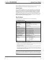
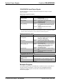
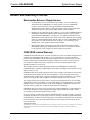
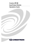
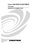
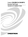
Crestron C2N-SPWS300 System Power Supply Operations Guide This document was prepared and written by the Technical Documentation department at: Crestron Electronics, Inc. 15 Volvo Drive Rockleigh, NJ 07647 1-888-CRESTRON All brand names, product names and trademarks are the property of their respective owners. ©2003 Crestron Electronics, Inc. Crestron C2N-SPWS300 System Power Supply Contents System Power Supply: C2N-SPWS300 1 Introduction...................................................................................................................1 Features and Functions ....................................................................................1 Specifications...................................................................................................3 Physical Description ........................................................................................4 Industry Compliance........................................................................................6 Setup .............................................................................................................................6 System Requirements ......................................................................................6 Network Wiring ...............................................................................................7 Identity Code ...................................................................................................8 Rack Mounting ..............................................................................................11 Hardware Hookup..........................................................................................11 Programming Software ...............................................................................................14 C2Net-Device Slot in Configuration Manager ..............................................15 Setting the Net ID in Device Settings ............................................................15 C2N-SPWS300 Symbol in Programming Manager ......................................16 Example Program ..........................................................................................18 Uploading and Upgrading...........................................................................................19 Communication Settings................................................................................19 Uploading a SIMPL Windows Program ........................................................21 Firmware Upgrade .........................................................................................23 Problem Solving .........................................................................................................25 Troubleshooting.............................................................................................25 Further Inquiries ............................................................................................26 Future Updates...............................................................................................26 Return and Warranty Policies .....................................................................................27 Merchandise Returns / Repair Service...........................................................27 CRESTRON Limited Warranty.....................................................................27 Operations Guide – DOC. 8190 Contents • i Crestron C2N-SPWS300 System Power Supply System Power Supply: C2N-SPWS300 Introduction Features and Functions The C2N-SPWS300 is a 300-watt system power supply designed for large Cresnet control systems (herein referred to as Cresnet system). It operates with an input of 100 to 240 VAC, 4A (maximum) and a noise rating less than 150mV. The C2N-SPWS300 provides regulated 24 VDC, 300 W to Cresnet system components. The C2N-SPWS300 is capable of delivering a nominal 75 watts of power at 24 volts DC on any of its eight channels. Each channel is accessed at the front panel of the unit via two black Cresnet type connectors per output. Outputs are limited to 75 watts (3.125 amps typical) by an electronic circuit breaker. Each output connector also has Cresnet Y-Z signals. All Cresnet signals are in parallel. Functional Summary • • • • NOTE: If all eight channels provide the maximum rating (75W), the unit would have to supply 600 watts total. That exceeds the C2N-SPWS300’s 300W capability. Therefore, a channel can deliver up to 75W, but every channel may not be fully utilized. Some channels may not be used at all. Operations Guide – DOC. 8190 24-volt, 300-watt Cresnet power supply Eight output channels (each with 75W rating) monitored and controlled by a Cresnet port Power switch allows for single-point shutdown. Useful when unit is not located at head end (refer to “Powering the Unit” on page 2 for details). Use Network Analyzer in SIMPL Windows to troubleshoot voltage levels. Channel Versus System Power Capabilities CHANNEL 1 CHANNEL 2 CHANNEL 3 CHANNEL 4 C2N-SPWS300 CHANNEL 5 CHANNEL 6 CHANNEL 7 CHANNEL 8 EACH OF THE EIGHT CHANNELS IS RATED FOR 75W (MAX) THE TOTAL SUM OF POWER PROVIDED VIA ALL EIGHT CHANNELS CANNOT EXCEED 300W System Power Supply: C2N-SPWS300 • 1 System Power Supply Crestron C2N-SPWS300 Powering the Unit NOTE: The C2N-SPWS300 is shipped with two power cable assemblies. One is supplied for standard 120 VAC, 60 Hz as available in the United States. The other has three un-terminated wires at one end and is supplied for international use or installation within the Crestron CAEN. Attach the correct cable assembly, connect it to AC power, and set the power switch on the left side of the unit to either the PWR ON or PWR OFF SLAVE position. Either position is capable of enabling the internal 300-watt power supply. Select one position over the other based on the type of control required. For example, for a large system with power supplies scattered throughout, it may be advantageous to implement the PWR OFF SLAVE position so that a single switch at the head end can execute a system-wide cold boot. Otherwise, one would have to turn off a switch at each power supply in the PWR ON position. PWR ON Position In the PWR ON position, the C2N-SPWS300 acts as a stand-alone system. All of the green LEDs illuminate successively as power is applied to each channel (1 through 8) until all eight channels are powered up. NOTE: Successive start up minimizes load current inrush current strain on the internal 300-watt supply. If the green LEDs do not illuminate, press and release the system RESET button. PWR OFF SLAVE Position In the PWR OFF SLAVE position, 24 VDC must be applied across the outer two pins (24 and G) of the NET connector located in the upper right corner to enable the internal supply. Once enabled, the green LEDs illuminate successively as power is applied to each channel (1 through 8) until all eight channels are powered up. When the power switch is in this position, 24 VDC from the Cresnet network is used to activate a relay, which in turn switches on the internal 24 VDC supply. If Cresnet power is removed, the C2N-SPWS300 turns off. Channel Details Each channel contains an electronic circuit breaker that detects over current faults for that channel. The electronic breakers are activated if the output power exceeds 75 watts nominally, but are guaranteed to always trip before output power reaches 100 watts. Each channel has 4-amp fuses to provide an additional means of limiting current. The fuses are not accessible to the user. When an over current fault has occurred on a channel, the red overload LED (OVRLD) on the front panel illuminates. The micro-controller attempts to automatically turn on each faulted channel twice before shutting off the channel and illuminating the red LED. At this point only pressing the RESET button associated with each channel allows the microcontroller to turn off the red OVRLD LED and to attempt to turn on the channel. In the event that the over current fault has been removed the channel powers up. If an overload is still present, the micro-controller attempts to turn on the channel an additional two times before the red LED illuminates again. Firmware continuously monitors all channels and all channel over current faults are reported to Cresnet. 2 • System Power Supply: C2N-SPWS300 Operations Guide - DOC. 8190 Crestron C2N-SPWS300 System Power Supply Pressing a RESET button during normal operations shuts off a channel for as long as the button is held down. If the button is released, the channel turns on. System Details In the event that the full 300 watts (12.5 amps) of the supply is exceeded, all eight channels turn off simultaneously, the eight red channel overload LEDs (OVRLD) illuminate, and the red system overload LED (OVRLD) illuminates. Pressing the system RESET button causes the unit to reset each channel individually until all channels are active (assuming the overload has been removed). Pressing the system RESET button during normal operations causes the unit to shut down all channels and turn them back on when the button is released. Specifications Specifications for the C2N-SPWS300 are listed in the following table. C2N-SPWS300 Specifications SPECIFICATION Input Power DETAILS 1 100 VAC to 240 VAC, 4 A, 50/60 Hz Output Voltage 24 VDC (regulated) Output Fuse Rating 4 A, 125 V, Time Delay, 1 fuse per channel (not serviceable) Ripple/Noise Less than 150 mV Default NET ID 15 Control System Update Files 2, 3, 4 2-Series Control System Update Version 2.004.CUZ or later File CNMSX-AV/Pro Update File Version 5.12.63X.UPZ or later CNRACKX/-DP Update File Version 5.12.63W.UPZ or later ST-CP Update File Version 4.02.4S.UPZ or later CEN/CN-TVAV Update File C2N-SPWS300 Firmware Version 5.12.63V.UPZ or later C2N-SPWS300.v1.3.upg or later Rack Space Required 3U high, 1U wide Operating Temperature 41° to 104°F (5° to 40°C) Humidity 10% to 90% RH (non-condensing) Dimensions Height: 5.19 in (13.18 cm) Width: 13.25 in (33.66 cm) Depth: 3.29 in (8.36 cm) Weight 5.3 lb (2.4 kg) 1 The C2N-SPWS300 ships with two cable assemblies; one for domestic use and the other for international use or installation within the Crestron CAEN. 2 The latest versions can be obtained from the Downloads | Software Updates section of the Crestron website (www.crestron.com). Refer to NOTE after the last footnote. 3 Crestron 2-Series control systems include the AV2, AV2 with Card Cage, CP2, CP2E, PAC2, MP2, MP2E, PRO2, and RACK2. 4 Filenames for CNX and ST-CP update files have a UPZ extension. Files on the website may be .zip or self-extracting .exe files containing the .cuz or .upz file. All can be obtained from the Downloads section of the Crestron website. To avoid program problems, make sure you are using the update file with the correct suffix letter (e.g., S, V, W, X) NOTE: Crestron software and any files on the website are for Authorized Crestron dealers and Crestron Authorized Independent Programmers (CAIP) only. New users may be required to register to obtain access to certain areas of the site (including the FTP site). Operations Guide – DOC. 8190 System Power Supply: C2N-SPWS300 • 3 System Power Supply Crestron C2N-SPWS300 Physical Description The C2N-SPWS300, shown after this paragraph, is housed in a sturdy 1/8-inch black anodized aluminum enclosure. A power selection switch and pigtail input power cable with an IEC320 socket are located to the left side of the unit. A screened overlay covers the front panel. The front panel has 17 four-pin network connectors. The data lines (Y and Z pins) on all network connectors are internally wired in parallel. One network connector in the upper right corner of the front panel must connect to a Crestron control system when the power switch is in the POWER OFF SLAVE position. Power and network LEDs support this connector. The other 16 network connectors are divided into eight pairs. Each pair is a channel used for integration of the unit into the Cresnet system. Each of the eight channels also has an overload and power LED as well as a reset button. In the lower right corner of the front panel there is an overload LED and reset button for the system. A recessed setup switch and LED are located above the system LED and button. This power supply has been designed to mount horizontally on its back in a rack cabinet or on a wall. At the shorter sides of the unit, the enclosure extends at a right angle to provide mounting flanges equipped with screw holes (hardware supplied by others). C2N-SPWS300 System Power Supply Ports With the exception of the IEC320 connector on a pigtail cord (for application of AC power), all connections to the C2N-SPWS300 are made via the ports on the front panel. The single four-pin network connector in the upper right corner on the front panel is used to accept 24 VDC when the power switch is set to the PWR OFF SLAVE position. Data provided to this connector is made available to all other network connectors since the data signals are in parallel. Refer to “Network Wiring” on page 7. The eight pairs of four-pin network connectors centrally located on the front panel are provided for distribution of power and data signals. Data and ground pins are internally wired in parallel from channel to channel. Each pair or channel is capable of delivering a nominal 75 watts of power at 24 VDC. Indicators A green LED (PWR) in the upper right corner of the front panel illuminates when the internal 300-watt power supply is enabled. Refer to “Powering the Unit” on page 2 for details. The yellow LED (NET) located below the PWR LED illuminates when the program running in the Crestron control system polls the unit. 4 • System Power Supply: C2N-SPWS300 Operations Guide - DOC. 8190 Crestron C2N-SPWS300 System Power Supply C2N-SPWS300 Physical Views 3.00 in (7.62 cm) 5.19 in (13.18 cm) 4.00 in (10.16 cm) 12.75 in (32.39 cm) 3.29 in (8.36 cm) 13.25 in (33.66 cm) Each power supply channel (1 through 8) has a green LED (PWR), which illuminates when 24V is present at that output. A red LED (OVLD) for each channel illuminates when there has been a short circuit or the load exceeds the nominal 75 watts for any channel. A system-wide red LED (OVLD) illuminates when the full 300 watts (12.5 amps) of the C2N-SPWS300 is exceeded. Pushbuttons A pushbutton (RESET) associated with each channel allows the user to reset the circuit breaker for each channel and turn on that channel. Power is restored to an overloaded channel if the excess load has been removed from the channel or the channel was set into overload because of a system overload caused by another channel. A system-wide pushbutton (RESET) is available to reset all eight-channel circuit breakers and turn on all channels assuming excessive loads have been removed. Operations Guide – DOC. 8190 System Power Supply: C2N-SPWS300 • 5 System Power Supply Crestron C2N-SPWS300 SETUP LED and Pushbutton The C2N-SPWS300 is TSID ready. The SETUP pushbutton and its associated LED located on the front panel are used for setup of the unit’s network ID during the initial configuration of a Cresnet system or when the device is being added/replaced. Refer to “Method B (Touch Settable IDs)” on page 9 for detailed information. Industry Compliance As of the date of manufacture, the C2N-SPWS300 has been tested and found to comply with specifications for CE marking and standards per EMC and Radiocommunications Compliance Labelling (N11785) NOTE: This device complies with part 15 of the FCC rules. Operation is subject to the following two conditions: (1) these devices may not cause harmful interference, and (2) these devices must accept any interference received, including interference that may cause undesired operation. Setup System Requirements A C2N-SPWS300 is necessary to supply power to modular "card cage" control systems (i.e., CNRACKX, CNRACKX-DP, and RACK2), since these units do not employ internal power supplies. C2N-SPWS300s may also be required in a Cresnet system managed by an integrated control system (i.e., AV2 or PRO2) if the power requirements of the system components are greater than the internal 50-watt power supply of the control system. To determine the number of C2N-SPWS300s necessary to power all Cresnet components in a particular Cresnet system, the total system power requirement must be calculated. This is accomplished by adding the power requirements of all system components. Refer to the leading specifications of each component for individual power requirements. The total system power requirements should include the control system, all cards in the control system, any expansion racks and associated cards, and any network units. Once the total system power requirement is calculated, the number of C2N-SPWS300s used should be selected such that their combined output wattage meets or exceeds the total system power requirement. Another important system factor to consider is the fact that a single network unit cannot be powered by two different C2N-SPWS300s. In other words, one C2NSPWS300, which is not being used to its full capacity, cannot contribute its unused power to 'help' another C2N-SPWS300 power the network units connected to it. For example, suppose a system consists of a RACK2 (cards included) with a power requirement of 20 watts, a CNX-DVP4 (50 watts required), five Crestron Isys™ touchpanels (each with a power requirement of 46 watts; including cards), and other ancillary Cresnet devices with a combined power requirement total of 25 watts. The total system power requirement is 325 watts. The first C2N-SPWS300 could power everything, but the CNX-DVP4 on seven channels for a total of 275 watts. A second power supply (C2N-SPWS3000 or CNPWS-75) could power the CNX-DVP4 for a total of 50 watts. 6 • System Power Supply: C2N-SPWS300 Operations Guide - DOC. 8190 Crestron C2N-SPWS300 System Power Supply Network Wiring CAUTION: Use only Crestron power supplies for Crestron equipment. Failure to do so could cause equipment damage or void the Crestron warranty. NOTE: When installing network wiring, refer to the latest revision of the wiring diagram(s) appropriate for your specific system configuration, available from the Downloads | Product Manuals | Wiring Diagrams section of the Crestron website (www.crestron.com). When calculating the wire gauge for a particular network run, the length of the run and the power factor of each network unit to be connected must be taken into consideration. If network units are to be daisy-chained on the run, the power factor of each network unit to be daisy-chained must be added together to determine the power factor of the entire chain. The length of the run in feet and the power factor of the run should be used in the following resistance equation to calculate the value on the right side of the equation. Resistance Equation R < 40,000 L x PF Where: R = Resistance (refer to table below). L = Length of run (or chain) in feet. PF = Power factor of entire run (or chain). The required wire gauge should be chosen such that the resistance value is less than the value calculated in the resistance equation. Refer to the table after this paragraph. Wire Gauge Values RESISTANCE (R) WIRE GAUGE 4 16 6 18 10 20 15 22 13 Doubled CAT5 8.7 Tripled CAT5 NOTE: All network wiring must consist of two twisted-pairs. One twisted pair is the +24V conductor and the GND conductor and the other twisted pair is the Y conductor and the Z conductor. NOTE: When daisy chaining network units, always twist the ends of the incoming wire and outgoing wire that share a pin on the network connector. After twisting the ends, tin the twisted connection with solder. Apply solder only to the ends of the twisted wires. Avoid tinning too far up or the tinned end becomes brittle and breaks. After tinning the twisted ends, insert the tinned connection into the network connector and tighten the retaining screw. Repeat the procedure for the other three network conductors. Operations Guide – DOC. 8190 System Power Supply: C2N-SPWS300 • 7 System Power Supply Crestron C2N-SPWS300 Identity Code NOTE: The C2N-SPWS300 can be polled in Cresnet while the power switch is in either position as long as the appropriate data signal (Y & Z) connections are made to any of the 17 NET connectors on the power supply. Refer to the NOTE on page 19 for a definition of Viewport. Every equipment and user interface within the Cresnet system requires a unique identity code (NET ID). These codes are two-digit hexadecimal numbers from 03 to FE. The NET ID of the unit must match the NET ID specified in the SIMPL Windows program. The NET ID of each C2N-SPWS300 has been factory set to 15. The NET IDs of multiple C2N-SPWS300s in the same system must be unique and changed from a personal computer (PC) via the Crestron Viewport, which is available through Crestron VisionTools Pro-e (VT Pro-e) or SIMPL Windows, or as a standalone utility. NOTE: If communication cannot be established, refer to the “Troubleshooting Communications” section in the respective Operations Guide for the control system. NOTE: VT Pro-e is a Windows compatible software package for creating Crestron touchpanel screen designs. SIMPL Windows is defined in “Programming Software” on page 14. There are two different methods for setting the C2N-SPWS300 NET IDs: Method A (Cresnet address-settable ID), described below, requires that a single C2N-SPWS300 be the only network device connected to the control system. This method is necessary with a CNX control system or with a 2-Series control system upgrade file (CUZ) version prior to 3.008. It is optional with later versions of the operating system. Method B (Touch Settable IDs), which begins on the next page, applies to C2NSPWS300s in a Cresnet system with 2-Series control system upgrade file (CUZ) version 3.029 or later. These upgrades enable Touch Settable ID (TSID) functionality, which makes it possible for the control system to recognize a network device via its serial number, which is stored in the device’s memory. This method does not require that any devices be disconnected from the network; NET IDs may be set with the entire Cresnet system intact. This method requires the use of the Crestron Viewport version 3.35 or later. Use the appropriate method to set the C2N-SPWS300 NET ID. Method A (Cresnet address-settable ID) 8 • System Power Supply: C2N-SPWS300 1. Ensure that the C2N-SPWS300 is the only device connected to the control system. 2. Open the Crestron Viewport. 3. Select Diagnostics | Establish Communications to verify communications. 4. Select Functions | Set Network ID. The software checks the baud rate and then opens the "Set Network ID" window. 5. In the "Set Network ID" window, select the C2N-SPWS300 from the Current Network Devices text window. 6. From the Choose the new network ID for the selected device (Hex): text box; select the new NET ID for the C2N-SPWS300. Operations Guide - DOC. 8190 Crestron C2N-SPWS300 System Power Supply 7. Click Set ID to initiate the change. This will display the "ID command has been sent" window. 8. In the "Command Complete" window, click OK. 9. In the Current Network Devices text window, verify the new NET ID code. 10. In the "Set Network ID" window, click Close. NOTE: The new NET ID code may also be verified by selecting Diagnostic | Report Network Devices in the Viewport (alternatively, select F4). 11. Repeat this procedure for each C2N-SPWS300 to be added to the network. Method B (Touch Settable IDs) Before using this method, you should have a list of all current network devices and their Net IDs, to avoid assigning duplicate IDs. Set Net ID by TSID These procedures are for TSID-enabled network devices during the initial configuration of a Cresnet system or when such devices are being added/replaced. 1. Ensure that all C2N-SPWS300s are connected to the control system. 2. Open the Crestron Viewport version 3.35 or later. 3. From the Viewport menu, select Functions | Assign Cresnet ID by Serial Number. The “Set Net ID by TSID” window appears. The window is first displayed with the data fields empty. “Set Net ID by TSID” Window 4. Operations Guide – DOC. 8190 Click on the Search for Touch Settable Devices button. The system searches the network and lists all TSID-enabled devices found. The list System Power Supply: C2N-SPWS300 • 9 System Power Supply Crestron C2N-SPWS300 is similar to the report produced by pressing F4 (Report Network Devices); the first eight digits of each line constitute the TSID number (hexadecimal form of the serial number). 5. As you enter either the serial number or TSID number of the device that requires a change, the corresponding TSID or serial number automatically appears in its appropriate field, and the list scrolls to and highlights the device listing. The listing should show the device’s current Cresnet ID. 6. Enter the Cresnet ID that the device should be set to and click OK. The number you enter should appear on the list. CAUTION: This function does not prevent you from setting duplicate IDs. Be sure to check current assignments before entering the desired Cresnet ID number. Serial Number to TSID Conversion This utility is useful in a case where there are multiple devices of the same type on a network, you need to locate a particular one, you know the TSID but not the serial number, and your site installation list is based on device serial numbers. In this (or the reverse) situation, do the following: 1. Open the Crestron Viewport. 2. From the Viewport menu, select Functions | Serial Number ÅÆ TSID Conversion Tool. The “Serial Number ÅÆTSID Conversion Tool” window is displayed. “Serial Number to TSID Conversion Tool” Window 3. Enter the serial number or TSID number as instructed; press the appropriate button to obtain the corresponding number. NOTE: Enter serial numbers, including spaces, exactly as they appear on the unit label. Alpha characters in serial numbers or TSID numbers may be entered in upper or lower case. 10 • System Power Supply: C2N-SPWS300 Operations Guide - DOC. 8190 Crestron C2N-SPWS300 System Power Supply Rack Mounting WARNING: To prevent bodily injury when mounting or servicing this unit in a rack, take special precautions to ensure that the system remains stable. The following guidelines are provided to ensure user safety. • When mounting this unit in a partially filled rack, load the rack from the bottom to the top with the heaviest component at the bottom. • If the rack is provided with stabilizing devices, install the stabilizers before mounting or servicing the units in the rack. NOTE: Reliable grounding of rack-mounted equipment should be maintained. Particular attention should be given to supply connections other than direct connections to the branch circuit (e.g., use of power strips). Material for rack mounting the C2N-SPWS3000 is provided with the C2N-RMAK (Crestron Rack Mounting Kit – sold separately). Hardware Hookup By design, the C2N-SPWS300 is rated to withstand elevated operating temperatures (internal temperatures can reach 122°F (50°C)). Therefore, the unit should be used in a well-ventilated area. The venting holes should not be obstructed under any circumstances. When the power supply approaches its maximum temperature rating, consider using forced air ventilation or implementing additional supplies to distribute the load. NOTE: Utilize the signals available from the C2N-SPWS300 SIMPL Windows symbol to track the internal temperature of the power supply. Hookup Preparation Prior to making hardware connections, it is assumed that all wiring is run and terminated with network connectors. However, the network connectors should not yet be plugged into the network units. Use an ohmmeter to verify that none of the four network conductors are shorted or crossed. Furthermore, ensure that each network unit has its unique ID code set. If necessary, refer to the product documentation for the appropriate ID code assignment procedure of each device. Hookup Methods NOTE: Loads should be connected to the eight channels so that all of the channels are utilized and loads are distributed as evenly as possible. Whether the power switch is set to the PWR ON or PWR OFF SLAVE position, the hookup diagrams, after this paragraph, illustrate the home run and daisy chain methods of connecting the C2N-SPWS300. They also illustrate multiple C2NSPWS300s within a single Cresnet system. Only use the methods shown; do not connect multiple power supplies together in parallel. If only one power supply is necessary, use either method and remove the expansion power supply. Operations Guide – DOC. 8190 System Power Supply: C2N-SPWS300 • 11 System Power Supply Crestron C2N-SPWS300 C2N-SPWS300 (PWR ON Position), Hardware Hookup C2N-SPWS300 24 Y Z G 24 Y Z G NET 24 Y Z G 24 Y Z G HOME RUN METHOD NETWORK UNIT 24 Y Z G NC NET NET 24 Y Z G 24 Y Z G NC EXPANSION POWER SUPPLY NETWORK DATA LINK TO ADDITIONAL EXPANSION POWER SUPPLY, C2N-SPWS300 OR CNPWS-75 ONLY CONNECT 24 VDC IF THE CONTROL SYSTEM DOES NOT EMPLOY AN INTERNAL POWER SUPPLY POWER EXPANSION (NETWORK DATA LINK TO EXPANSION POWER SUPPLY, C2NSPWS300 OR CNPWS-75) NET NET CONTROL SYSTEM 24 Y Z G NET NETWORK UNIT 24 Y Z G 24 Y Z G NETWORK UNIT DAISY CHAIN METHOD NOTE: Never connect multiple C2N-SPWS300s in parallel. NOTE: Always disconnect AC power to the C2N-SPWS300 supplying power to a Cresnet system before connecting a network unit to that system or installing a card in the control system. 12 • System Power Supply: C2N-SPWS300 Operations Guide - DOC. 8190 Crestron C2N-SPWS300 System Power Supply C2N-SPWS300 (PWR OFF SLAVE Position), Hardware Hookup C2N-SPWS300 NET 24 Y Z G NET NETWORK UNIT 24 Y Z G 24 Y Z G HOME RUN METHOD 24 Y Z G NET 24 Y Z G 24 Y Z G CONTROL SYSTEM 24 Y Z G NC NET NET 24 Y Z G 24 Y Z G NC EXPANSION POWER SUPPLY NETWORK DATA LINK TO ADDITIONAL EXPANSION POWER SUPPLY, C2N-SPWS300 OR CNPWS-75 POWER EXPANSION (NETWORK DATA LINK TO EXPANSION POWER SUPPLY, C2NSPWS300 OR CNPWS-75) 24 Y Z G 24 Y Z G NET NET NET NETWORK UNIT NETWORK UNIT NETWORK UNIT DAISY CHAIN METHOD 24 Y Z G Hookup Procedure Operations Guide – DOC. 8190 1. Connect each network unit to the appropriate network connector. 2. Connect AC power to the C2N-SPWS300. 3. If a PC (running SIMPL Windows) is available, connect the PC to the Cresnet system via the computer port on the control system. 4. From SIMPL Windows, select Tools | Viewport to open the Viewport. 5. Select Diagnostics | Report Network Devices (alternatively F4) to verify that all network units are properly connected to the Cresnet system. System Power Supply: C2N-SPWS300 • 13 System Power Supply Crestron C2N-SPWS300 Programming Software Have a comment about Crestron software? Direct software related suggestions and/or complaints to Crestron via email ([email protected]). Do not forward any queries to this address. Instead refer to “Further Inquiries” on page 26 for assistance. Setup is easy thanks to Crestron’s Windows-based programming software. Following are the minimum software requirements for the PC: • SIMPL Windows version 2.04.11 or later. Requires SIMPL+ Cross Compiler version 1.1. • Crestron Database is required by SIMPL Windows, but no special version is needed for the C2N-SPWS300. NOTE: The following are acceptable file extensions for programs that include a C2N-SPWS300, developed for specific control system types: .smw projectname.smw (source file) .spz projectname.spz (compiled file for 2-series) .bin projectname.bin (compiled file for CNX generation) .csz projectname.csz (compiled file for CNX generation with SIMPL+) .ush projectname.ush (compiled file for CNX generation with SIMPL+ header file) .usp projectname.usp (source code module for SIMPL+) SIMPL (Symbol Intensive Master Programming Language) Windows is Crestron's software for programming Crestron control systems. It provides a well-designed graphical environment with a number of workspaces (i.e., windows) in which a programmer can select, configure, program, test, and monitor a Crestron control system. The objects that are used in SIMPL are called symbols. SIMPL Windows offers drag and drop functionality in a familiar Windows® environment. NOTE: The following assumes that the reader has knowledge of SIMPL Windows. If not, refer to the extensive help information provided with the software. NOTE: In the following description, the PRO2 control system is used. This section describes a sample SIMPL Windows program that includes a C2N-SPWS300 power supply. Configuration Manager is where programmers “build” a Crestron control system by selecting hardware from the Device Library. In Configuration Manager, drag the PRO2 from the Control Systems folder of the Device Library and drop it in the upper pane of the System Views. The PRO2 with its associated communication ports is displayed in the System Views upper pane. PRO2 System View 14 • System Power Supply: C2N-SPWS300 Operations Guide - DOC. 8190 Crestron C2N-SPWS300 System Power Supply The System Views lower pane displays the PRO2 system tree. This tree can be expanded to display and configure the communications ports. Expanded PRO2 System Tree C2Net-Device Slot in Configuration Manager To incorporate the C2N-SPWS300 power supply into the system, drag the C2NSPWS300 from the Power Supplies folder of the Device Library and drop it in the System Views. The PRO2 system tree displays the touchpanel in slot 9 with a default NET ID of 15 as shown in the following illustration. NOTE: The first C2N-SPWS300 in a system is preset with a NET ID of 15 when its symbol is dragged into the upper pane of System Views. Additional units are assigned different NET ID numbers as they are added. C2Net Device, Slot 9 Setting the Net ID in Device Settings Double-click the C2N-SPWS300 icon to open the “Device Settings” window. This window displays the C2N-SPWS300 device information. If necessary, select the Net ID tab to change the Net ID, as shown in the following figure. Operations Guide – DOC. 8190 System Power Supply: C2N-SPWS300 • 15 System Power Supply Crestron C2N-SPWS300 “Device Settings” Window for the C2N-SPWS300 NOTE: SIMPL Windows automatically changes NET ID values of a device added to a program if a duplicate device or a device with the same default NET ID already exists in the program. Always ensure that the hardware and software settings of the NET ID match. For NET ID hardware settings details, refer to “Identity Code” on page 8. C2N-SPWS300 Symbol in Programming Manager Programming Manager is where programmers “program” a Creston control system by assigning signals to symbols. The following diagram shows the C2N-SPWS300 symbol in the SIMPL Windows’ Programming Manager. Detail View of the C2N-SPWS300 in SIMPL Windows’ Programming Manager 16 • System Power Supply: C2N-SPWS300 Operations Guide - DOC. 8190 Crestron C2N-SPWS300 System Power Supply Signal Types Signals interconnect the various devices and logic symbols that comprise a SIMPL program. Signals can be one of three types: digital, analog, or serial. For any given signal, the signal type is determined by its driving source. That is, if the symbol that drives the signal has an analog output, then, by definition, the connecting signal is analog. In SIMPL Windows, the signal types are color-coded as follows: Digital = Blue Analog = Red Serial = Black Undefined/Other = Green NOTE: “Other” signals are a combination of the three basic types (e.g. many symbols accept either analog or serial signals where the combination is shown as a green signal). The signal type is displayed on the Status Bar when the signal is highlighted. For additional information, refer to Doc. 6120, Crestron SIMPL Windows Symbol Guide. It may be downloaded from the Downloads | Product Manuals | Software section of the Crestron website (www.crestron.com). Digital Signals A digital signal contains one bit of information and usually takes on one of two values: 1 or 0. These two digits can represent the logical values true and false, and they can be represented in an electronic device by the states on/off or high/low, recognized as two voltage levels. (Other common descriptors are active/inactive.) Analog Signals Unlike digital signals, analog signals can vary continuously in value, in the same manner as a parameter such as volume, temperature, or pressure. Analog signals contain 16 bits of information, which means that this type of signal can have values ranging from 0 to 65535 (216-1). This 16-bit property makes analog signals useful for controlling devices that do not have discrete settings, such as volume controllers, pan/tilt head controllers, and lighting dimmers. Serial Signals Serial signals are much like analog signals, in that they, too, contain 16 bits of information. However, whereas the value of an analog signal is used directly-to control volume or temperature, for instance–the value of the serial signal is used as a pointer to a location in memory that contains a string of characters. When a serial signal is routed to a symbol, that symbol can identify the signal as serial rather than analog and it will automatically look at the data it points to. Thus serial signals are used to facilitate the transmission of serial data (strings of characters). These signals can be generated by incoming data on a COM port or by a symbol that has a serial output. Operations Guide – DOC. 8190 System Power Supply: C2N-SPWS300 • 17 System Power Supply Crestron C2N-SPWS300 C2N-SPWS300 Input/Output Signals The following tables list and give functional descriptions for the power supply outputs and inputs. Digital Output Signal Descriptions OUTPUT DESCRIPTION Chan1_ Faulted through Chan8_Faulted High/1 = Fault occurs on an individual channel, power is cut off. Low/0 = No channel fault detected. High/1 = System fault occurs, power to all channels is cut off. Low/0 = No fault detected. High/1 = Internal temperature of the unit and total load approaches the maximum rating of the unit. Low/0 = Temperature/total load are within tolerance. Main_Faulted Temp_Warning* * This signal returns to its low state (0) after the internal temperature decreases or the load is reduced. The user may not know this action took place, unless this signal is latched (i.e., D Flip Flop) in SIMPL Windows. Therefore, the high state (1) can be retained for troubleshooting purposes. Digital Input Signal Descriptions INPUT DESCRIPTION Chan1_Reset through Chan8_Reset High/1 = Power to a given channel is cut off for as long as the signal is held high. Power is restored on trailing edge. Low/0 = No external reset detected. High/1 = Shuts off system power (drives all faults low). Power is restored on trailing edge. Low/0 = No reset detected. High/1 = Allows analog outputs to report current voltage for each channel and current inside temperature of the unit. Low/0 = All analogs are zero. High/1 = Reports temperature in Celsius (Temp x 10). Low/0 = Reports temperature in Farhrenheit (Temp x 10). Main_Reset Status_Report_En Temp Format Analog Output Signal Descriptions OUTPUT DESCRIPTION Chan1_Voltage through Chan8_Voltage Temp Current voltage of each channel is displayed. Inside temperature of unit is displayed. The display format depends on Temp Format (digital input signal). Example Program An example program for the C2N-SPWS300 is available from the Crestron FTP site (ftp://ftp.crestron.com/Examples). Search for the file C2NSPWS300.ZIP that contains the example program, associated files and a README.TXT file that describes the program. 18 • System Power Supply: C2N-SPWS300 Operations Guide - DOC. 8190 Crestron C2N-SPWS300 System Power Supply Uploading and Upgrading Assuming a PC is properly connected to the entire system, Crestron programming software allows the programmer to upload programs to the system after their development. However, there are times when the files for the program are compiled and not uploaded. Instead, compiled files may be distributed from programmers to installers, from Crestron to dealers, etc. Even firmware upgrades are available from the Crestron website as new features are developed after product releases. In those instances, one has the option to upload via the programming software or to upload and upgrade via the Crestron Viewport. NOTE: The Viewport utility accomplishes multiple system tasks, primarily via an RS-232 or TCP/IP connection between the control system and a PC. It is used to observe system processes, upload new operating systems and firmware, change system and network parameters, and communicate with network device consoles and touchpanels, among many other tasks. Viewport can also function as a terminal emulator for generic file transfer. All of these functions are accessed through the commands and options in the Viewport menus. Therefore, for its effectiveness as a support and diagnostic tool, the Crestron Viewport may be preferred over development tools when uploading programs and projects. The following sections define how one would upload a SIMPL Windows program or upgrade the firmware of the C2N-SPWS300. However, before attempting to upload or upgrade, it is necessary to establish communications. Communication Settings NOTE: For laptops and other PCs without a built-in RS-232 port, Crestron recommends the use of PCMCIA cards, rather than USB-to-serial adapters. If a USB-to-serial adapter must be used, Crestron has tested the following devices with good results: Belkin (large model) F5U103 I/O Gear GUC232A Keyspan USA-19QW Other models, even from the same manufacturer, may not yield the same results. The procedure in this section provides details for RS-232 communication between the PC and the control system. If TCP/IP communication is preferred, consult the latest version of the Crestron e-Control Reference Guide (Doc. 6052) or the respective Operations Guide for the control system. These documents are available from the Downloads | Product Manuals section of the Crestron website (www.crestron.com). Refer to the following figure for a typical connection diagram when uploading files NOTE: Use a standard DB9 male to female “straight-through” cable. Operations Guide – DOC. 8190 System Power Supply: C2N-SPWS300 • 19 System Power Supply Crestron C2N-SPWS300 Typical Connection Diagram when Uploading a Project 1. Open the Crestron Viewport. Either launch the stand-alone version of Viewport, or start SIMPL Windows and from the menu bar, select Tools | Viewport. 2. Refer to the following figure. From the Viewport menu, select Setup | Communications settings (alternatively, depress Alt+D) to open the “Port Settings” window. Setup | Communications Settings Command 3. 20 • System Power Supply: C2N-SPWS300 Select RS-232 as the connection type. Verify that an available COM port (COM 1 is shown after this step) is selected, and that all communication parameters and necessary options from the “Port Settings” window are selected as shown after this step. Click the OK button to save the settings and close the window. Operations Guide - DOC. 8190 Crestron C2N-SPWS300 System Power Supply “Port Settings” Window NOTE: Different control systems may require different communication settings. Refer to each control system’s Operations Guide for proper communication settings. NOTE: The baud rate may need to be set to 38400 baud (Cresnet speed) for a successful transfer. NOTE: Communications can be verified by selecting Diagnostics | Establish Communications (Find Rack). This should display a window that gives the COM port and baud rate. If communication cannot be established, refer to the “Troubleshooting Communications” section in the respective Operations Guide for the control system. Uploading a SIMPL Windows Program A control system source file has the extension .smw. A compiled SIMPL Windows file has the extension .spz for a 2-Series control system, .bin for CNX generation, and .csz for CNX generation with SIMPL+. The SIMPL Windows file can be uploaded to the control using SIMPL Windows or via the Crestron Viewport. Upload via SIMPL Windows 1. Start SIMPL Windows. 2. Select File | Open to view the “Open” window, navigate to the SIMPL Window file (.smw), and click Open. 3. Select Project | Transfer Program. Upload via Crestron Viewport 1. Operations Guide – DOC. 8190 Verify that the procedure for “Communication Settings” that begins on page 19 has been performed. System Power Supply: C2N-SPWS300 • 21 System Power Supply Crestron C2N-SPWS300 2. As shown after this step, select File Transfer | Send Program (alternatively, press Alt+P) from the Viewport menu. File Transfer | Send Program Command 3. The “Send Program” window appears, as shown after this step. Click Browse, locate the compiled file (.spz) and click Open. This will display the program's header information and enable one or both of the What to Send check boxes. If the program does not contain any SIMPL+ modules, only the SIMPL Program check box will be enabled. If it does contain SIMPL+ modules, then the SIMPL+ Program(s) check box will also be enabled. Select one or both check boxes and then click Send Program to begin the transfer. NOTE: Refer to the respective Operations Guide for the control system for details about the other fields shown on the “Send Program” window. “Send Program” Window 4. 22 • System Power Supply: C2N-SPWS300 To verify that the program has been transferred successfully, select Diagnostics | Report Program Information or press F7. This should display a window that provides details about the current program loaded into the control system. Operations Guide - DOC. 8190 Crestron C2N-SPWS300 System Power Supply Firmware Upgrade A firmware upgrade file has the extension .csf. To take advantage of all the C2N-SPWS300 features, it is important that the unit contains the latest firmware available. Therefore, please check the Crestron website (http://www.crestron.com/downloads/software_updates.asp) for the latest version of firmware. Not every product has a firmware upgrade, but as Crestron improves functions, adds new features, and extends the capabilities of its products, firmware upgrades are posted. To upgrade the firmware, complete the following steps. 1. Make sure that “Communication Settings” that begins on page 19 has been performed. 2. As shown after this step, select File Transfer | Load Network Device from the Viewport menu. File Transfer | Load Network Device Command 3. As shown after this step, select the NET ID of the C2N-SPWS300 and then click OK. The “Open” window appears (refer to the subsequent graphic). “Select Network ID” Window NOTE: When transferring any Cresnet file (touchpanel project/firmware), lower the port speed baud rate to 38400 to match the Cresnet bus speed. Operations Guide – DOC. 8190 System Power Supply: C2N-SPWS300 • 23 System Power Supply Crestron C2N-SPWS300 “Open” Window 4. 24 • System Power Supply: C2N-SPWS300 Browse to the desired .upg file and click Open to begin the transfer. Operations Guide - DOC. 8190 Crestron C2N-SPWS300 System Power Supply Problem Solving Troubleshooting The table below provides corrective action for possible trouble situations. If further assistance is required, please contact a Crestron customer service representative. C2N-SPWS300 Troubleshooting TROUBLE POSSIBLE CAUSE(S) CORRECTIVE ACTION Power LED C2N-SPWS300 is not (PWR) is receiving power. not illuminated. Unit is not plugged in. PWR ON switch is not in correct position. Unit is in slave System overload LED configuration and (OVRLD) is power cable is not illuminated. connected. Total power draw from unit exceeds 300 watts. Combination of high ambient temperature and excessive load.* Some network Varied. units are not receiving power. If the overload LED (OVRLD) for one or more channels illuminates, the power drawn per channel exceeds 75 watts. Verify that AC outlet is active and supplying power. Plug in unit. Verify that PWR ON switch is in correct position. Connect power cable. Remove excessive load and press system RESET button. Place unit in a well-ventilated area, reduce load, press system RESET button and may possibly require cycling of power switch. From SIMPL Windows, select Tools | Network Analyzer and perform voltage level tests on the troubled network unit. Refer to the SIMPL Windows help file for details. Remove excessive load and press the channel RESET button. * Track Temp_Warning (digital output signal) from the C2N-SPWS300 symbol. This signal returns to its low state (0) after the internal temperature decreases or the load is reduced. The user may not know this action took place, unless this signal is latched (i.e., D Flip Flop) in SIMPL Windows. Therefore, the high state (1) can be retained for troubleshooting purposes. Operations Guide – DOC. 8190 System Power Supply: C2N-SPWS300 • 25 System Power Supply Crestron C2N-SPWS300 Further Inquiries If, after reviewing this Operations Guide for the C2N-SPWS300, you cannot locate specific information or have questions, please take advantage of Crestron's award winning customer service team in your area. Dial one of the following numbers. • In the US and Canada, call Crestron's corporate headquarters at 1-888-CRESTRON [1-888-273-7876]. • In Europe, call Crestron International at +32-15-50-99-50. • In Asia, call Crestron Asia at +852-2341-2016. • In Latin America, call Crestron Latin America at +5255-5093-2160. • In Australia and New Zealand, call Crestron Pacific at +613-9480-2999. Future Updates As Crestron improves functions, adds new features, and extends the capabilities of the C2N-SPWS300, additional information and programming examples may be made available as manual updates. These updates are solely electronic and serve as intermediary supplements prior to the release of a complete technical documentation revision. Check the Crestron website (www.crestron.com) periodically for manual update availability and its subjective value. Updates are available from the Downloads | Product Manuals section and are identified as an “Addendum” in the Download column. 26 • System Power Supply: C2N-SPWS300 Operations Guide - DOC. 8190 Crestron C2N-SPWS300 System Power Supply Return and Warranty Policies Merchandise Returns / Repair Service 1. No merchandise may be returned for credit, exchange, or service without prior authorization from CRESTRON. To obtain warranty service for CRESTRON products, contact the factory and request an RMA (Return Merchandise Authorization) number. Enclose a note specifying the nature of the problem, name and phone number of contact person, RMA number, and return address. 2. Products may be returned for credit, exchange, or service with a CRESTRON Return Merchandise Authorization (RMA) number. Authorized returns must be shipped freight prepaid to CRESTRON, Cresskill, N.J., or its authorized subsidiaries, with RMA number clearly marked on the outside of all cartons. Shipments arriving freight collect or without an RMA number shall be subject to refusal. CRESTRON reserves the right in its sole and absolute discretion to charge a 15% restocking fee, plus shipping costs, on any products returned with an RMA. 3. Return freight charges following repair of items under warranty shall be paid by CRESTRON, shipping by standard ground carrier. In the event repairs are found to be non-warranty, return freight costs shall be paid by the purchaser. CRESTRON Limited Warranty CRESTRON ELECTRONICS, Inc. warrants its products to be free from manufacturing defects in materials and workmanship under normal use for a period of three (3) years from the date of purchase from CRESTRON, with the following exceptions: disk drives and any other moving or rotating mechanical parts, pan/tilt heads and power supplies are covered for a period of one (1) year; touchscreen display and overlay components are covered for 90 days; batteries and incandescent lamps are not covered. This warranty extends to products purchased directly from CRESTRON or an authorized CRESTRON dealer. Purchasers should inquire of the dealer regarding the nature and extent of the dealer's warranty, if any. CRESTRON shall not be liable to honor the terms of this warranty if the product has been used in any application other than that for which it was intended, or if it has been subjected to misuse, accidental damage, modification, or improper installation procedures. Furthermore, this warranty does not cover any product that has had the serial number altered, defaced, or removed. This warranty shall be the sole and exclusive remedy to the original purchaser. In no event shall CRESTRON be liable for incidental or consequential damages of any kind (property or economic damages inclusive) arising from the sale or use of this equipment. CRESTRON is not liable for any claim made by a third party or made by the purchaser for a third party. CRESTRON shall, at its option, repair or replace any product found defective, without charge for parts or labor. Repaired or replaced equipment and parts supplied under this warranty shall be covered only by the unexpired portion of the warranty. Except as expressly set forth in this warranty, CRESTRON makes no other warranties, expressed or implied, nor authorizes any other party to offer any warranty, including any implied warranties of merchantability or fitness for a particular purpose. Any implied warranties that may be imposed by law are limited to the terms of this limited warranty. This warranty statement supercedes all previous warranties. Trademark Information All brand names, product names, and trademarks are the sole property of their respective owners. Windows is a registered trademark of Microsoft Corporation. Windows95/98/Me/XP and WindowsNT/2000 are trademarks of Microsoft Corporation. Operations Guide – DOC. 8190 System Power Supply: C2N-SPWS300 • 27 Crestron Electronics, Inc. 15 Volvo Drive Rockleigh, NJ 07647 Tel: 888.CRESTRON Fax: 201.767.7576 www.crestron.com Operations Guide – DOC. 8190 06.03 Specifications subject to change without notice.