1
122
Installation of PML4 Linearity Board / Mettler
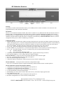
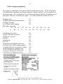
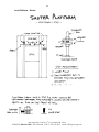
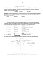
The PML4 board is an add-in board, which gives PM and PJ instruments a linearity potentiometer. This
board fits in instruments with chassis size of approximately 12" x 8". Linearity adjustment is often required
after replacement of a front coupling. No electronic adjustment or circuit can compensate a damaged cell, or
one which has been assembled incorrectly. To successfully install the PML4, you'll need excellent
soldering and desoldering skill. Without that skill, there is a risk of damaging the main board.
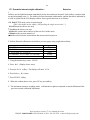
1) Take anti-static precautions. Work on a static-dissipating workbench, or wear an anti-static
bracelet. See the anti-static precautions on the following page.
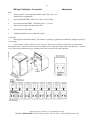
2) Remove the instrument cover (one screw) , then remove any shroud which covers the cell. Some
instruments won't have a shroud. If a data-interface board is mounted on the right side of the instrument,
remove it (one screw). Release the display board from the plastic clips which secure it, then unplug
connector #1. Set the display aside (careful, VERY expensive), then unplug the remaining three connectors.
Remove the three screws, then remove the entire main board from the instrument chassis.
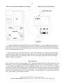
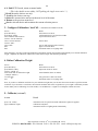
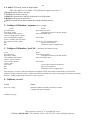
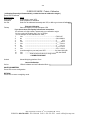
3) Locate IC13. Remove it by clipping all 8 pins at the IC body, then de-soldering each lead from the board.
Remove the solder from the holes vacated by the IC pins. The holes must be clear to receive the PML4
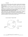
board. Place the 8 pins of the PML4 into the 8 holes vacated by IC-13. When properly oriented, the
potentiometer adjustment will be accessible from the edge of the board, and the bare wire will point forward.
The underside of the PML4 will rest against the top of a rectangular capacitor on the main board. Solder all 8
connections.
(Continued next page)
IES Corporation, 2324 SE 11th Ave, Portland, OR 97214
PHONE: 1-800-541-0852/1-503-230-0646 FAX: 1-503-235-2535 e-mail: [email protected]