1
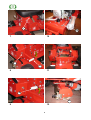
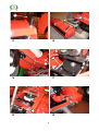
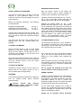
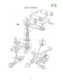
OPERATORS MANUAL
&
SPARE PARTS LIST
TURF TROOPER 3
K
A
E
B
1
4
H
C
L
2
5
I
D
H
J
G
F
3
6
1
L
M
7
10
J
G
8
11
G
R
9
12
2
T
P
13
16
Q
O
14
17
C
15
18
3
19
21
T
20
22
4
CONTENTS
Page
CERTIFICATE OF CONFORMITY
SPECIFICATIONS
INTRODUCTION
SAFETY INSTRUCTIONS
ASSEMBLING THE MACHINE
OPERATING THE MACHINE
SAFETY INTERLOCK SWITCHES
TO START THE ENGINE
TO STOP THE ENGINE
STEERING
WORKING INSTRUCTIONS
SPEED CONTROL
CYLINDER DRIVE CLUTCH
CUTTING WITH THE MACHINE
THROTTLE CONTROL
BRAKE & PARKING BRAKE
LIFTING & LOWERING MOWER UNITS
FRONT CYLINDERS
REAR CYLINDER
MAINTENANCE
LUBRICATION
ENGINE LUBRICATION
MACHINE LUBRICATION
BATTERY
TYRES
ADJUSTMENTS
STEERING LINKAGE
DRIVE TRAIN ADJUSTMENTS
MAIN DRIVE BELT
CYLINDER DRIVE BELT ADJUSTMENT
CYLINDER CLUTCH DRIVE BELT
CYLINDER CLUTCH ADJUSTMENT
HEIGHT OF CUT
CUTTING CYLINDER TO BOTTOM BLADE
TO ADJUST
PARKING BRAKE
ILLUSTRATED PARTS LISTS
MAIN FRAME ASSEMBLY
DRIVE ASSEMBLY
STEERING ASSEMBLY
CUTTING CYLINDER ASSEMBLIES
LINKAGE ASSEMBLIES
ELECTRICAL ASSEMBLY
WIRING DIAGRAM
6
7
8
8
9
9
10
10
10
10
10
10
10
11
11
11
11
11
11
11
12
12
12
12
12
12
12
12
12
13
13
13
13
13
14
14
15
16
18
22
24
28
30
32
5
EC DECLARATION OF CONFORMITY
I, the undersigned,
of Allen Power Equipment Ltd., The Broadway, Didcot, Oxon OX11 8ES,
certify that the machine described below: Category
Make
Type
Model
Cutter
Lawnmower
ALLEN
Ride-on
Turf Trooper III
60” (1530mm) Cylinder
Comply with the following Directives.
79/113/EEC
89/336/EEC as amended by 92/31/EEC
89/392/EEC
84/538/EEC as amended by 88/180/EEC and
88/181/EEC
2000/14/EC
Signed:………………………………
Peter Bateman
Managing Director
6
SPECIFICATIONS
MODEL
ENGINE
GXV 270
MANUFACTURER
Honda
POWER HP
8.5
MAX PERMISSIBLE (KW)
6.4
ENGINE SPEED (RPM)
3600
SOUND POWER LEVEL (LWA) dB(A)
99
SOUND PRESSURE LEVEL (LPA) dB(A)
86.4
EXPLANATION OF SYMBOLS
Warning
Read Instruction Manual before operating
Engaged
Parking Brake
Disengaged
Engaged
Cutter clutch
Disengage
7
INTRODUCTION
SAFETY INSTRUCTIONS
The ALLEN TURF TROOPER 3 is an advanced
ride-on cylinder mower designed to cut grass
quickly, efficiently and economically, giving your
lawn the velvet finish only a quality cylinder
mower can deliver.
Please ensure that the instructions
contained in this manual are read
carefully and fully understood by any person
likely to operate the Trooper.
Before starting the engine the operator should
check that the drive pedal is in neutral, the drive
lever to the cylinder transmission is in the
‘disengaged’ position and the parking brake is
applied. Do not run the engine in a confined
space; exhaust gases contain carbon monoxide,
which is an odourless and deadly poisonous gas.
Attractive styling and a high standard of build
along with detailed attention to user comfort and
ease of operation combine to produce the
ultimate in mowing for the large garden owner.
Large wheels and rear wheel steering on the Turf
Trooper 3 mean that not only will the machine
cope with undulating ground but it has the ability
to turn in its own length, making mowing around
trees or posts effortless.
Before starting the engine, check that the cutting
cylinders are free to run with no obstruction
present and that they are not blocked with grass
or debris from previous use.
Pedal control gives totally variable forward and
reverse motion thus allowing the exact cutting
speed for every mowing application.
Make sure all parts are in good working order
such as tyres, steering, cutting blades and belts
and that all guards are in position.
Six blades on each seven-inch cylinder ensure
that the machine leaves a well-manicured look to
any lawn.
When driving the machine for the first time keep
travelling speed low and become familiar with all
the controls in an area where there is plenty of
room to manoeuvre.
From the moment you turn the key and the
engine springs to life until you park the machine
and fold the front cylinders for storage, mowing
the grass has never been easier.
When travelling and not wishing to cut grass,
ensure all cutting units are lifted and latched into
the raised transport position and the cylinder
transmission is disengaged.
This manual will help you to get to know your Turf
Trooper and obtain the best results from it. The
Trooper has been designed to the highest
standards. With proper care and maintenance it
will provide many years of reliable and enjoyable
service.
Ensure that the area to be cut is free of all
obstructions, which can be removed, such as
stones and metal objects.
Obstructions, which cannot be removed, should
be negotiated carefully to prevent accidental
damage to the cutters.
PLEASE READ THIS MANUAL
THOROUGHLY BEFORE STARTING OR
USING YOUR TURF TROOPER 3
If working on slopes or undulating ground be
particularly careful and avoid conditions, which
may cause the machine to slide.
Maximum angles permissible for use are:
15º max. down slope in forward
15º across slope
15º max. up slope in forward
15º max. backing down slope in reverse
On damp or uneven ground these angles
should be reduced.
Start and park the machine on level ground.
Before leaving the driving position disengage all
drives, set the parking brake and stop the engine.
8
The seat is fitted with a safety cut-out switch
which stops the engine as soon as the operator
dismounts unless certain parameters are met.
Should this happen, the ignition switch must also
be turned off to prevent the battery discharging.
ASSEMBLING THE MACHINE
Always wear stout shoes and suitable clothing.
Fit the front cylinders noting that they are
“handed”. These are fitted with the cylinder lift
arms in the raised position. With the cylinders
located on the arms install the cylinder retainer
collar ‘A’ with the lock pin ‘B’ and secure with ‘R’
clip, Fig. 1.
The machine comes partially assembled however
the following operations are necessary prior to
use.
When operating the machine beware of children
and animals; take care with bystanders, they may
be deaf or blind.
Before making any adjustments or clearing a
blockage, STOP the engine and remove ignition
key. When making adjustments to any part of the
machine, particularly the cutting cylinders, take
care not to trap fingers and do not attempt to free
jammed or blocked cylinders by using the foot.
The retainer collar is designed in such a way that
it can only be fitted and removed with the
cylinders in the raised position.
Fit the front cylinder drive belts and adjust. (See
section on adjustments).
Note:
Lift the steering column and locate the steering
console on the front two lugs pushing the console
back. Lower the steering column so that it locates
on the steering spigot ‘C’, Fig. 2.
Whilst every precaution is taken in the selection
of materials and components used in the
manufacture of this machine. To ensure optimum
performance and reliability, Allen Power
Equipment Limited cannot accept liability for any
damage to this machine or any possible lack of
efficiency resulting from the improper use or
incorrect maintenance of said machine.
Use the special lock pin to connect the steering
column to the steering gear Fig. 3.
Fit the rear cover and screws ‘E’ Fig. 4.
Allen Power Equipment Limited cannot accept
any liability for damage to this machine or third
party through operational negligence.
Locate and secure the seat.
Fill and charge the battery, fuel and oil the
engine. Check engine manufactures information
for the correct grade of oil to be used.
Allen Power Equipment Limited reserve the right
to alter specifications and prices as and when
necessary
Run the machine and check that all the
necessary functions perform correctly.
OPERATING THE MACHINE
Read the Safety Instructions at the front
of this manual.
Ensure that the engine is in an operational
condition, i.e. oil to level, petrol present, Drive
Pedal ‘F’ is in neutral, the Cylinder Drive (lever)
‘G’ is disengaged and the Parking Brake ‘H’ is
engaged, Fig. 5 & 6.
9
WORKING INSTRUCTIONS
With the engine running at full speed, the
machine may be used in either travelling or
cutting mode. If travelling, ensure that all the
SAFETY INTERLOCK SWITCHES
The machine is fitted with a number of interlock
switches to give additional safety to the
customer. Here are some tips relating to the use
of the switches:-
cylinders are lifted and latched ‘K’, Fig. 1 and ‘L’,
Fig. 5 into the travelling position and that the
Cylinder Drive (lever) ‘G’, Fig. 6 is disengaged.
Before the operator dismounts, the following
must be effected:
Engage the Parking Brake
Select neutral on Drive Pedal
Disengage Cylinder Drive (lever)
Release the Parking Brake ‘H’, Fig. 6 and
depress the Drive Pedal ‘F’, Fig. 6. The pedal is
not an accelerator but controls the movement of
the machine while not altering the engine speed.
To move forward slowly, depress the front of the
pedal. The further the pedal is pressed the faster
the machine will go. To select neutral, simply
bring the pedal to the central rest position to
which it will automatically return. To select
reverse slowly depress the rear of the pedal.
‘H’, Fig. 6
‘F’, Fig. 6
‘G’, Fig. 6
If all the above criteria are met the operator may
dismount with the engine still running however if
any of the above criteria are omitted the engine
will stop.
CYLINDER DRIVE CLUTCH
The engine will also stop if the operator tries to
engage drive with the Parking Brake still
engaged.
The Cylinder Drive (lever) ‘G’, Fig. 6 situated on
the forward right hand side of the central seat
mounting box, is the cutter drive clutch lever and
this controls the drive to all cutter
TO START THE ENGINE
Set the Throttle Control ‘I’. Fig. 6 to the choke
position for cold start (midway through speed
range for warm engine). Turn the key ‘J’, Fig. 6
clockwise until resistance is felt and then turn
fully to operate the starter.
units. With the lever ‘G’ in the lowered position
Fig. 6, the drive is disconnected and it should
always be in this position when stopping the
machine.
When the engine starts, release the key. With the
engine running cold, allow it to warm up and then
move the Throttle Control ‘I’ from the choke
position to fast run.
With the engine running, the Cylinder Drive may
be engaged by lifting up the lever ‘G’ slowly until
it locks in position, Fig. 6 when all cylinders will
then be revolving.
TO STOP THE ENGINE
Do not engage the Cylinder Drive when the
mower units are in the transport position.
Operate the Throttle Control ‘I’ to the “slow run”
position and turn the Ignition Switch ‘J’, Fig. 6
anti-clockwise until the engine stops.
SPEED CONTROL
STEERING
Forward or reverse speed control is achieved by
operating the Drive Pedal ‘F’, Fig. 6 on the right
hand footwell. The pedal operates a heavy-duty
hydrostatic gearbox to give a smooth and
progressive speed change. The further the pedal
is depressed the faster the machine travels.
The rear wheel steering is operated by a drag link
from the steering wheel giving complete
manoeuvrability.
Become
familiar
with
machine
handling before attempting higher
speeds or difficult manoeuvres.
Do not make rapid changes from forward to
reverse as it could effect the machine’s stability.
Always disengage the Cylinder Drive (lever) ‘G’
when in the transport position.
Always lift all cylinders before travelling.
10
THROTTLE CONTROL
CUTTING WITH THE MACHINE
The Throttle Control ‘I’, Fig 6 is a combined
choke and engine speed control housed in one
unit. The lever should be placed in the relevant
position for the function required.
The Trooper is designed to have all three
cylinders operating at the same time. There is no
method of disconnecting separate cylinders,
therefore all cylinders must be lowered from the
transport position on to the grass. With the
engine running at half speed, engage Cylinder
Drive (level) ‘G’, Fig. 6 by pulling the right-hand
lever up and locking it in the raised position on
the left latch plate. When all the cylinders are
revolving, the Throttle ‘I’ should then be set to full
speed.
BRAKE AND PARKING BRAKE
When stopping the engine, raise the Parking
Brake ‘H’, Fig. 5 and lock it on the lift latch plate.
To release the Parking Brake ‘H’, Fig. 6 lift it over
the latch and allow it to lower.
Depress the Drive Pedal ‘F’ to select the required
forward speed. The length of grass will determine
the height of cut and the forward speed.
The Parking Brake should always be engaged
whenever the machine is stopped or left
unattended.
If the grass is long, 3 to 4 inches (76 to 102mm)
then the cylinders will need to be set fairly high
(adjustment is available from ½in to 2½in [12mm
to 64mm]) and a low forward speed selected.
LIFTING & LOWERING MOWER UNITS
Ensure that all the cylinders are disengaged, the
Drive Pedal ‘F’ is in neutral, the Parking Brake ‘H’
is ON in the ‘Engaged’ position and the engine is
switched OFF at ‘J’.
If the grass is short then a lower height setting
can be used and a faster forward speed may be
selected. Full forward speed should only be used
when the cutters are disengaged and are in the
transport position and only when a clear straight
run is available.
FRONT CYLINDERS
To Lower
The Throttle ‘I’ should be set at maximum to
allow the engine to run at its governed speed.
Each front unit has two lift handles and a latch
‘K’, Fig. 1. To lower, lift the handle towards the
centre of the machine, raise the latch ‘K’ and
lower the cylinder unit to the ground.
Do not drop the unit as damage may occur.
Never allow the engine to labour, ease off the
Drive Pedal ‘F’ to slow the forward speed or alter
the height of cut.
To Raise
MAINTENANCE
Read the Safety Precautions.
Reverse the above procedure.
The following information is given to enable the
owner/operator to obtain good service from the
machine.
REAR CYLINDER
To Lower
Although maintenance has been reduced to a
minimum, regular attention to lubrication,
adjustments and cleanliness is important.
Grasp the Rear Cylinder Lift Lever ‘L’, Fig. 5
located to the left of the central seat mounting
box. Move the lever ‘L’ forward to lower the
cylinder unit.
Left or right hand is determined from the
operating position sitting on the machine.
Do not drop the unit as damage may occur.
MAINTENANCE PRECAUTIONS
To Raise
When refuelling, stop the engine, do not smoke
and use a funnel when pouring fuel from a can to
ensure that none is spilt onto hot parts of the
engine, i.e. exhaust silencer, cylinder, etc.
Reverse the above procedure pulling back the
lever ‘L’ until it clicks into the raised position, Fig.
5.
11
Use Castrol L.M. grease or equivalent.
If working on lifted parts ensure that adequate
support is provided.
Occasionally lubricate all other moving parts by
oil can, in particular the Throttle Control at the
lever and engine ends, cylinder unit latches,
neutral adjustment plungers, exposed screw
threads on mower adjustments etc.
Do not alter engine speed above the maximum
quoted in the engine specification. Before making
any adjustment or clearing a blockage, STOP the
engine. When making adjustments to any part of
the machine, particularly the cutting cylinders,
take care not to trap fingers and do not attempt to
free jammed or blocked cylinders by using the
foot.
BATTERY
On receiving the new machine fill the battery with
concentrated acid and fully charge prior to initial
use. This ensures battery longevity and should
be carried out by the supplying dealer.
LUBRICATION
In normal ambient conditions (above 4º
Centigrade or 40º Fahrenheit) an SAE 30 oil is
recommended for the cutter ‘T’ drive gearbox and
the hydrostatic transaxle. For temperatures below
this consult your supplying dealer.
Check that the vent-tube ‘N’, Fig. 11 is fitted and
is clear. The output should pass through the hole
in the chassis below the battery.
ENGINE LUBRICATION
BATTERY
ACID
IS
HIGHLY
CORROSIVE AND EXTREME CARE
SHOULD BE TAKEN
The machine is fitted with a four stroke engine,
this being lubricated by oil in the crankcase.
TYRES
The engine is filled with oil at manufacture.
However, care must be taken to ensure that the
oil is to the engine manufacturer’s required level
(see engine manual) prior to and during use.
Take care not to overfill the crankcase. Use only
oils to engine manufacturer’s specifications.
Keep all tyre pressures at 15Ib/in2 (1.0 bar).
Adhere carefully to the engine manufacturer’s
operating
and
maintenance
instructions,
particularly with regard to air cleaner servicing.
STEERING LINKAGE
ADJUSTMENTS
Read the Safety Precautions.
The drag link can be adjusted quite simply by
removing the clip from the rear of the link rod and
adjusting the length prior to re-insertion.
MACHINE LUBRICATION
The transaxle and bevel gearboxes are filled with
lubricant on assembly and no further attention
should be required.
DRIVE TRAIN ADJUSTMENTS
Most adjustments that may be required from time
to time are carried out by first removing the main
access panel on the top of the machine. To effect
this, undo the eight Access Panel Screws ‘E’, Fig.
4 and remove the panel. By withdrawing the
Steering Column Pin ‘C’, Fig. 2 & 15, the steering
column can then be disengaged allowing the
removal of the entire steering housing. This gives
free access to the majority of the working parts
and makes for ease of service.
The cylinder bearings are “sealed for life” and so
do not require lubrication.
Grease should be applied, every 25 working
hours, to the greasers fitted to all the mower pivot
points, Fig. 12 and to all the roller greasers.
MAIN DRIVE BELT
The Main Drive Belt ‘O’, Fig. 14 and 15, is
tensioned by slackening the four engine mount
bolts and tensioning the adjuster screw. ‘M’ fig
10. Retighten securely.
12
If belt replacement is necessary, remove the
main access panel as detailed above ‘R’. Then
remove the Locating Spigot Bar from the
fan/pulley assembly, Fig. 15 and separate the
fan/pulley assembly, Fig. 15 and the coupling,
Fig. 2. The Belt ‘O’ can be replaced easily.
CYLINDER CLUTCH ADJUSTMENT
Lay the belt into its pulley and the engine pulley.
Refit the Fan/Pulley assembly and Locating
Spigot Bar allowing the rubber coupling to align
with the coupler halves.
It is not necessary to remove the clutch rod,
disconnect the clevis pin from the clevis. Adjust
on the thread to suit. Reassemble.
The clutch is designed to be partially selfadjusting, however periodic inspection should be
carried out to ensure that optimum performance
is being attained.
Note: - It is not necessary to overtighten on
clutching.
Once the four Spigot Bar retaining bolts have
been replaced and tightened, the belt ‘O’ can be
tensioned as described above.
Should adjustment be necessary, tighten or
loosen the clutch rod by removing it and adjusting
its length, Fig. 18.
Correct tension is when the belt can be deflected
12mm at its mid point with finger pressure.
HEIGHT OF CUT
Take extreme care not to trap fingers
or clothing.
The cutting height of each cylinder unit is
determined by the position of the rear rollers.
Adjustments can be varied from ½in to 2½in
(12mm to 64mm).
DO NOT USE THE ELECTRIC STARTER
Check that the belt is installed correctly and that
it is not rubbing anywhere.
To Adjust
1. Park the machine on flat, level ground. Stop
the engine, engage the Parking Brake ‘H’ and
disengage the Cylinder Drive (Lever) ‘G’.
CYLINDER DRIVE BELT ADJUSTMENT
Screw the Cylinder Drive Belt Adjuster ‘P’ Fig. 16
away from the body of the machine to increase
tension on the cylinder drive belt and towards the
machine to slacken the belt tension. The tension
should be set to a deflection of 20mm as shown
in Fig. 15.
2. Slacken the Knurled knob ‘R’ fig 12 and
reposition the roller end plates using the
teeth. These are arranged in sets of 3 for
ease of identification.
3. A practical tip when positioning the roller.
Remember the blade cutting edge is ½in
(12mm) up from the underside of the bottom
blade.
CYLINDER CLUTCH DRIVE BELT
Having removed the main access panel, remove
the Main Drive Belt ‘O’, Figs. 14 and 15, by
loosening and removing the Locating spigot Bar,
‘R’ Fig. 2 and separating the coupling Fig. 2.
CUTTING CYLINDER TO BOTTOM BLADE
Then undo the screw, Fig. 17, which secures the
top of the cutter ‘T’ drive pulley and raise the
pulley.
Please note that cylinders are
sharp and care must be taken at all
times.
The belt ‘Q’, Figs. 15 and 17, can now be
removed freely and replaced.
To check that a cutting cylinder is set correctly in
relation to the bottom blade, proceed as follows: -
To replace, reverse the above procedure.
Stop the engine, slacken the Cylinder Drive Belt
Adjusters ‘P’, Fig. 16, hold a thin piece of paper
between the edge of the bottom blade and a
spiral cutter and rotate the cylinder manually. If
correctly set, the paper should cut cleanly along
the length of the bottom blade.
Slackening the engine mount bolts, allows the
engine to move forward
If
13
it
does
not
then
adjustment
may
be
necessary. Removal of the Cylinder Belt greatly
eases this operation.
GUARANTEE
If there is any component, or components,
manufactured by ALLEN POWER EQUIPMENT
LTD that is found to be defective within 12
months from the date of purchase (or in the case
of a machine used for hire purposes, 45 days).
ALLEN POWER EQUIPMENT LTD undertake to
replace the faulty component/components free of
charge through authorised dealers.
Note:
The performance of a blunt cylinder/bottom blade
will not be improved by tightening the cylinder to
the bottom blade. In such cases the
cylinder/bottom blade needs to be sharpened.
TO ADJUST
The following are NOT covered under this
Guarantee:
The cylinder is supported by two swivel bearing
housings. See Fig.13. Raise the adjustment
levers ‘T’ from their locked position, rotate about
180° and lower the lever. Turning ANTI
CLOCKWISE moves the cylinder down to the
bottom blade. Once the blades are cutting evenly
return the adjuster to its locked (locked position)
1. A NEW MACHINE — which has been subject
to operation in excess of recommended
capacities, misuse, negligence or accident,
or has been altered or modified in a manner
not
authorised by ALLEN
POWER
EQUIPMENT LTD.
Always complete the adjustment by moving the
cylinder DOWN. This ensures that any free play
in the mounting is taken out
2. TRANSPORTATION charges — to and from
an authorised dealer.
ALLEN POWER EQUIPMENT LTD operate a
policy of continual improvement and reserve the
right to alter product specification without giving
prior notice.
Always be extremely careful when
rotating the cylinder by hand. Always
use paper long enough to keep fingers away
from the cutting edge. Never attempt to touch
or check cylinders when they are moving
under power or even when the engine is
running.
After each season, we recommend that you
have your machine serviced by your dealer,
preferably between October and January, to
avoid delay at the start of the following
season.
Remember:
Unless belts are removed, turning ONE cylinder
TURNS ALL THREE.
REAR CYLINDER PITCH
To ensure that the rear cylinder cuts the same
height as the front two adjust the pitch using the
M8 clamp bolts Fig. 20. This may be necessary
after striking foreign objects.
PARKING BRAKE
The internal disc brake fitted to the transaxle is
operated by the Parking Brake Lever ‘G’, Fig. 5
and is self-adjusting, no further maintenance is
necessary.
14
!
!"
!
"
"
#
! $
%
&
!
%
'
'!
(
%
!
%
'
!
#
#
! $
! $
"
!
"
"
!"
!
"
( "
'
!
"
"
'
!
!
!
"
"
!
!
!"
!
"
!
"
(
(
!
"
"
)
!
(
"
"
!
"
"
*
'!
#
!
"
$
CUTTING CYLINDER ASSEMBLIES
ITEM No.
1
2
3
4
5
6
7
8
9
10
11
12
13
14
15
16
17
18
19
20
21
22
23
24
25
26
27
28
29
30
31
32
33
34
35
36
PART No.
27984
27985
27983
23917
02137
23741
03467
23979
23980
23981
23985
25349
25348
25350
02454
02977
02496
23722
02449
02520
23922
23923
04498
23708
25670
25684
01219
03320
23716
02339
25344
25834
25345
01217
25680
02200
03226
03226
03944
02529
25679
DESCRIPTION
REEL ASSEMBLY (LH)
REEL ASSEMBLY (RH)
REEL ASSEMBLY (REAR)
BODY (LH)
BODY (RH)
BODY (REAR)
GREASE NIPPLE
PULLEY
ROLL PIN
GUARD (LH)
GUARD (RH)
GUARD (REAR)
SPACER
SPACER
SCRAPER
SPACER
HEX HD BOLT, M8 X 60
WASHER, M8
NYLOC NUT, M8
DEFLECTOR
HEX HD SETSCREW, M8 X 20
NUT, M8
MOWER REEL (LH)
MOWER REEL (RH & REAR)
RATCHET HANDLE
ADJUSTER ROD
ADJUSTER NUT
BEARING HOUSING
BEARING
TOLERANCE RING
SKID FOOT
HEX HD BOLT, M8 X 25
LOCATION BUSH
BOTTOM BLADE SUPPORT
BLADE
CSK HD SCREW
REAR ROLLER
BEARING
CIRCLIP INTERNAL
ADAPTOR
LOCK NUT, M12
SPRING WASHER, M12
SCRAPER BAR
25
QTY
1
1
1
1
1
1
A/R
1
2
1
1
1
1
1
1
1
2
A/R
A/R
1
2
A/R
1
1
2
2
2
2
2
2
2
4
4
1
1
7
1
2
2
2
2
2
2
(
#
#
!"
(
$
$
#
#
#
#
'
$
$
$
$
*
*
!
" +
# ' $
#
$
!
(
"
(
!
"
"
(
(
(
!
!
"
"
#
!
, -../01.23.-0./0
, -../01.2/-0.4
, -../01.2/5675/-8./05-.20
!
'(
!
!
%
$
% 9 -../01./0:75-8
"
autoguide equipment
Heddington, Nr Calne, Wiltshire, SN11 0PS
Telephone: +44 (0) 1380 850885
Fax: +44 (0) 1380 850010