1
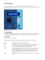
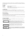
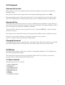
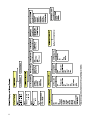
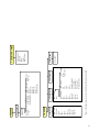
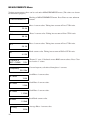
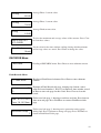
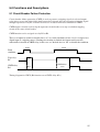
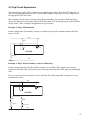
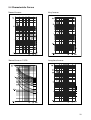
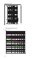
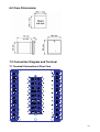
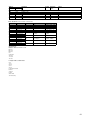
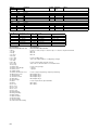
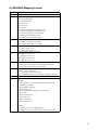
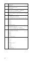
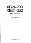
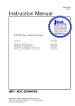
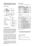
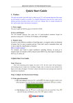
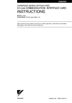
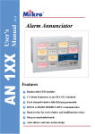
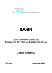
V1.2
Combined Overcurrent and Earth Fault Relay
Three-phase, three stages phase overcurrent setting
Low-set and high-set earth fault setting
IDMT and definite time setting
Thermal overload protection
Trip circuit supervision
RS232 and RS485 MODBUS-RTU communication
Fault, alarm and tripping records with timestamp
Multifunction programmable outputs
Multifunction external digital inputs
Revision History
V1.0
V1.1
May 2012
Aug 2013
V1.2
Jan 2014
First version.
Adding IRF option. Correcting MODBUS register.
Correct typo-error at Fault Records Menu, MODBUS register
Correct typo-error at Input Menu, Typical Connection Diagram
Table of Contents
1.0 Introduction ........................................................................................................... 4
1.1 Symbols and Definitions............................................................................................................4
2.0 Front Panel............................................................................................................. 5
2.1 LCD Display ..............................................................................................................................5
2.2 Keypad .......................................................................................................................................5
2.3 LEDs ..........................................................................................................................................6
2.4 RS232 Port .................................................................................................................................6
2.5 Default Display ..........................................................................................................................6
2.6 Alarm Condition.........................................................................................................................6
3.0 Password................................................................................................................. 7
Password Protection.........................................................................................................................7
Password Entry ................................................................................................................................7
Changing Password..........................................................................................................................7
4.0 Menus ..................................................................................................................... 7
4.1 Menu Contents ...........................................................................................................................7
MEASUREMENTS Menu.............................................................................................................10
RECORDS Menu........................................................................................................................... 11
CONFIGURATION Menu.............................................................................................................12
PROTECTION G1 Menu ..............................................................................................................16
PROTECTION G2 Menu ..............................................................................................................19
INPUT Menu .................................................................................................................................19
OUTPUT Menu .............................................................................................................................21
COMMUNICATION Menu...........................................................................................................24
5.0 Functions and Descriptions ................................................................................ 25
5.1 Circuit Breaker Failure Protection ...........................................................................................25
5.2 Thermal Overload Protection...................................................................................................26
5.3 Trip Circuit Supervision...........................................................................................................27
5.4 Characteristic Curves ...............................................................................................................29
6.0 Case Dimensions.................................................................................................. 31
7.0 Connection Diagram and Terminal ................................................................... 31
7.1 Terminal Connection at Rear View ..........................................................................................31
7.2 Typical Connection Diagram ...................................................................................................33
8.0 Technical Data...................................................................................................... 34
9.0 MODBUS Protocol .............................................................................................. 38
9.1 MODBUS Functions................................................................................................................38
9.2 MODBUS Register ..................................................................................................................40
9.3 MODBUS Mapping Format ....................................................................................................45
1.0 Introduction
The purpose of this manual is to provide information necessary to install, operate and maintain the
MK2200L relay.
MK2200L provides protections for 3 independent phase overcurrent elements and one nondirectional earth-fault element. All these elements are connected to the current transformers of the
feeders to be protected.
There are 2 sets of current inputs, for 1A and 5A rated CTs.
Using the front panel, the user can easily navigate through the user friendly menu, read
measurements and change settings. The relay status and alarm or trip records are displayed on the
back-lit LCD also.
There is a RS232 port available on the front panel and a RS485 port on the rear terminals. Using
MODBUS RTU protocol, all stored information can be read and settings can be modified with a PC
loaded with Mikro setting software.
MK2200L has 4 configurable output relays. They can be activated by any of the protection
functions available in the relay. There is also 1 output relay for internal fault indication. There are 2
configurable logic inputs for various functions.
1.1 Symbols and Definitions
In this manual and on the relay, unless the context otherwise requires, the following symbols and
abbreviations shall
apply throughout:AC
Ack
Alrm
CT
CBFP
Chg
CLPU
DC
Dmd
Dmnd
DMT
EF
Genrl
IDMT
IL1
IL2
IL3
Io/IN
Invrse
Ip
IRF
LED
OC
:
:
:
:
:
:
:
:
:
:
:
:
:
:
:
:
:
:
:
:
:
:
:
Alternating current
Acknowledge
Alarm
Current transformer
Circuit Breaker Failure Protection
Change
Cold Load Pickup
Direct current
Demand
Demand
Definite time
Earth fault
General
Inverse definite minimum time
Phase 1 current
Phase 2 current
Phase 3 current
Earth (fault) current
Inverse
Input
Internal Relay Failure
Light emitting diodes
Overcurrent
OL
PU
RCRD
Rmote
Rst
Strt
TCS
Thml
:
:
:
:
:
:
:
:
Overloaded
Pickup
Record
Remote
Reset
Start
Trip circuit supervision
Thermal
2.0 Front Panel
Using the front panel, the user can easily navigate through the user friendly menu, read
measurements and change settings. The relay status and alarm or trip records are displayed on the
back-lit LCD also.
MK2200L Front panel
2.1 LCD Display
The LCD has 2 lines with 16 characters each. Back light is on when a key is pressed and remain on
for a predefined time duration. The brightness can be adjusted to suit the lighting conditions.
2.2 Keypad
There are 6 keys on the front panel.
Up, Down, Enter and Esc are used to navigate through the menus and adjust the settings.
Up
Down
Esc
:
:
:
Enter
Clear
:
:
Record
:
Scroll up the menus or increase setting value.
Scroll down the menus or decrease setting value.
To exit from menus, submenus or to cancel setting value change. Press and
hold for 1.5 seconds to return to default display from any submenu.
To enter submenus or to confirm setting value change.
To reset tripping, reset latched relay. If “CLEAR” Scroll is enabled (under
Configurations-> Display menu) and during no alarm status, it can be
used to scroll through Phase Overcurrent and Earth Fault settings, and to
return to default display from any submenu if pressed and hold for 1.5
seconds.
To display Alarm records. To display successive records, press Record key
again.
To display record date and time, press Enter. To exit , press Esc/Enter. To delete individual record,
press Clear. To delete all records, go to the end of the records and “Clear all alarm?” will be shown,
press Clear to clear.
2.3 LEDs
Aux LED
Trip LED
Alarm LED
:
:
:
Indicates auxiliary power to the device
Indicates tripping.
Blinks to indicate non acknowledge alarm (or tripping). Steady on when the
alarm is acknowledged by pressing any key
2.4 RS232 Port
The front panel RS232 port has the same MODBUS RTU protocol as the RS485 port on the rear
terminal, though with fixed communication settings: 38400bps, 1 stop bit, even parity, address 1.
All stored information can be read and settings can be modified with a PC loaded with the supplied
Mikro setting software.
2.5 Default Display
By default the LCD displays the current value measured for IL1, IL2, IL3 and Io. Input and output
status as well as date and time can be shown by pressing Up or Down to change the default display
page. Pressing Esc always return to current value display.
As soon as an alarm or trip is detected, the display jumps to record display to show the latest record.
2.6 Alarm Condition
During an alarm or tripping condition, Alarm LED blinks. Alarm record pops up. Any keypress
change the Alarm LED to steady on.
Example of Alarm record title page, showing record 1 out of total 2
records. Press Enter to enter sub page for this record. Press
Record/Down to show next alarm. Press Up to show previous alarm.
Press Esc to return to Default Display. Press Clear to clear the alarm.
If the condition still persists, the alarm cannot be cleared.
Alarm record sub page, showing record date and time. Press
Esc/Enter/RECORD to return to Alarm Record title page.
Clearing all record menu is shown when Up is pressed during display
of Record 1's title page, or RECORD/Down is pressed during display
of Last records title page. Press Clear to clear all Alarm record or Esc
to cancel.
3.0 Password
Password Protection
Relay settings can be view anytime but locked from being changed. A password is required for
changing setting.
The password consists of four digit numbers. The factory default password is set as 0000.
The programming mode is indicated with the letter "P" on the right hand side of the display. The
letter "P" remains present as long as the password is active. (2 minutes if there is no key action).
Password Entry
The input of the password is requested as soon as a modification of a parameter is made. The user
enters each one of the 4 digits by using up or down key and validates each digit with Enter. If Esc is
pressed in between, the password entering is terminated.
“Password OK” is shown if correct password is entered. “Password ERROR” is shown if wrong
password is entered.
The display returns to the point of the preceding menu. Pressed Enter again to modify the setting.
If no key is pressed after 2 minutes, the settings are locked. A new password
request is associated with any subsequent setting change.
Changing Password
To change the password, go to Op Parameter -> Password menu. Enter current password to unlock,
after that the display shows current password. Press Enter again to enter the new password.
4.0 Menus
The menu is divided into 7 main menus and their corresponding submenus. To enter Main menu,
press Enter during default display.
The menu can be navigated by pressing Up, Down, Enter and Esc keys. There is no need of a
password when reading settings and measured values.
4.1 Menu Contents
The Main menu consists of 8 items:
1. MEASUREMENTS
2. RECORDS
3. CONFIGURATION
4. PROTECTION G1
5. PROTECTION G2
6. INPUT
7. OUTPUT
8. COMMUNICATION
(Func is Trip)
tI>?
tI>>?
tI>>>?
tIo>?
tIo>>?
Thml OL?
tAux 1?
tAux 2?
Remote?
(Func is Start)
I>?
I>>?
I>>>?
Io>?
Io>>?
Thml OL(Alarm)?
Aux 1(Alarm)?
Aux 2(Alarm)?
TCS (Alarm)?
Demand (Alarm)?
(Func is CBFP)
Delay
Include Aux?
* Some of the menu items are not shown if relevant functions are disabled
Reset
tI>?
tI>>?
tI>>>?
tIo>?
tIo>>?
Thml OL?
tAux 1?
tAux 2?
Remote?
Relay 2-4 Func
Reset
Relay 1 Func
(Trip only)
7.5 Maint mode
(Func is Blocking) (Func is TCS)
Block I>?
TCS delay
Block I>>?
Block I>>>?
Block Io>?
Block Io>>?
Block Thml OL?
7.2-7.4 Relay 2-4
(Func is Reset)
Rst Trip/Alarm
Rst Thermal θ%
7.1 Relay 1
7.OUTPUT
(Func is Aux 1/2)
Aux timer
Input Func
Input Type
6.1-6.2 Input 1,2
6.INPUT
Relay IRF?
7.6 Relay IRF
Communication?
Baud Rate
Parity
Stop Bit
Relay Address
8.COMMUNICATION
MEASUREMENTS Menu
Various measurement values can be read under MEASUREMENTS menu. (The values are shown
for illustrative purpose).
,
"1
, 2 "
Heading of MEASUREMENTS menu. Press Enter to enter submenu
content.
Phase 1 current value. Taking into account of Line CT Pri ratio.
Phase 2 current value. Taking into account of Line CT Pri ratio.
Phase 3 current value. Taking into account of Line CT Pri ratio.
Earth current value. Taking into account of E/Gnd CT Pri ratio.
θ
!
"
#
Thermal % state. Calculated on true RMS current values. Press Clear
to clear the % values.
Current frequency calculated from phase 1 currents.
$ %& '()
*+
Peak Phase 1 current value.
, -
, -
Peak Phase 2 current value.
, -
Peak Phase 3 current value.
.
Peak Earth current value.
, .
/0
Average Phase 1 current value.
/0
Average Phase 2 current value.
/0
Average Phase 3 current value.
3
Average Earth current value.
/0
, - 4 /0
"
To clear the maximum and average values of the currents. Press Clear
to clear these values.
"
5 '6 7
'
Set the value for the time window (rolling) during which maximum
and average values are stored. Press Enter to change the value.
RECORDS Menu
8
Heading of RECORDS menu. Press Enter to enter submenu content.
"
Fault Records Menu
$&
Heading of Fault Record submenu. Press Enter to enter submenu
content.
( 69
:;
<
( / "
= &
Example of Fault Record title page, showing trip element, source,
value and record number 1. Press Up or Down to show another record
of Enter to enter sub page for this record. Press Clear to clear this
record.
Fault record sub page 1, showing record date and time. Press down to
show next sub page. Press Esc/Enter to return to Fault Record title
page.
Fault record sub page 2, showing active protection setting group
during fault. Press Up/down to change sub page. Press Esc/Enter to
return to Fault Record title page.
, 0' &6
Fault record sub page 3, showing L1 current during fault. Press
Up/down to change sub page. Press Esc/Enter to return to Fault
Record title page.
, 0' &6
Fault record sub page 4, showing L2 current during fault. Press
Up/down to change sub page. Press Esc/Enter to return to Fault
Record title page.
, 0' &6
Fault record sub page 5, showing L3 current during fault. Press
Up/down to change sub page. Press Esc/Enter to return to Fault
Record title page.
Fault record sub page 6, showing Lo current during fault. Press Up to
previous sub page. Press Esc/Enter to return to Fault Record title page.
, 0' &6
Clearing all records
Clearing all record menu is shown when Up is pressed during display
of Record 1's title page, or Down is pressed during display of Last
records title page. Press Clear to clear all record or Esc to cancel.
( 69
Event Records Menu
/'
= '
Heading of Fault Record submenu. Press Enter to enter submenu
content.
( 69
9
:;
Example of Event title page. Press Enter to enter sub page for this
record.
Event record sub page, showing record date and time. Press Esc/Enter
to return to Fault Record title page.
Clearing all records
Clearing all record menu is shown when Up is pressed during display
of Record 1's title page, or Down is pressed during display of Last
records title page. Press Clear to clear all record or Esc to cancel.
( 69
CONFIGURATION Menu
82$ =1
82
Heading of CONFIGURATION menu. Press Enter to enter submenu
content.
Op parameter Menu
Heading of Op Parameter submenu. Press Enter to enter submenu
content.
8 >
> 997
9(
$
This password is required when changing relay settings. Press Enter to
enter a new password. The user needs to enter existing password to
???? unlock, after that the display shows current password. Press Enter
again to enter the new password.
6
Model name of this relay
'
,@
Version of the firmware.
7
$ %& '()
*+
Set the nominal value of the line frequency. Press Enter to change this
value.
CT Ratio Menu
Heading of CT Ratio menu. Press Enter to enter submenu content
'
Set the rated primary current of the Line/Phase CT.
>
='6
>
Set the rated primary current of the Earth/Ground CT.
Note: The CT secondary should be connected to 5A or 1A CT input terminal of the relay according
to Primary CT type. The display current is calculated by the formula:
Current at CT input terminal / CT input terminal type x CT Pri (setting above)
For example if:
Current at CT input terminal = 3A,
CT input terminal type = 5A,
CT Pri = 200A,
The display value = 3/5 x 200 = 120A
Date & Time Menu
Heading of Date & Time menu. Press Enter to enter submenu content.
4
Displays the date. Press Enter to change the date.
<
$
, , AAAA
Set the date format for display. Press Enter to change between
DD/MM/YYYY and MM/DD/YYYY.
Displays the time. Press Enter to change the time, starts from hour,
minute and am/pm (if 12 hour format is selected). Second will be reset
to 0 when enter is pressed for any of the digit.
Set the time format. Press enter to change between 12 and 24 hour.
$
B! &
Group Select Menu
= & "
Heading of Group Select menu. Press Enter to enter submenu content.
(
!0 = & C)
, '&
"
Set whether the protection group setting is change by Menu or Input.
One of the input function must be set to 'Select Group' if Input is
selected. Press Enter to change.
If above is set to Menu, this will set the active protection group. Press
Enter to change.
'0 = &
Display Menu
9
Heading of Display menu. Press Enter to enter submenu content.
)
8'
'
D 0! ' 99
, 6&
Set how long the LCD backlight remains on after no key is pressed.
Press Enter to change.
Set the brightness of the LCD backlight. Press Enter to chage.
E
F"(
2
Set if Clear key can be used (during no alarm or trip state) to scroll
through the default display pages, Phase OC and Earth OC settings
(for currently selected group), as well as to return to Default Display
from Record display. This is useful when Up, Down, Enter and Esc
key is inaccessible due to the front panel is covered and locked.
Cold Load Pickup Menu
Cold Load Pickup allows selected settings to be altered to respond to temporary overload conditions
that may occur during cold starts. These conditions could be switching on large heating load after a
extended cooling period, air conditioning, or inductive loads that draw high starting current like
motor.
To enable cold load pickup, one of the input functions has to be set to Cold Load PU.
6
>1
Heading of Cold Load Pickup menu. Press Enter to enter submenu
content.
6 >1
Scaling value, in percent, for the cold load pick up assigned to the
selected thresholds.
/
#
Delay timer setting (tCL) for the Cold Load Pickup function.
>1
9
Assign the I> time delay threshold with the cold load pick up function.
>1
A 9
Assign the I>> time delay threshold with the cold load pick up function.
>1
A 9
Assign the I>>> time delay threshold with the cold load pick up
function.
>1
A 9
Assign the Io> time delay threshold with the cold load pick up function.
>1
A 9
Assign the Io>> time delay threshold with the cold load pick up
function.
>1
A 9
>1 !
Assign the Thermal Overload time delay threshold (Iθ>) with the cold
load pick up function.
8
A 9
Demand Alarm Menu
Demand alarm is used to give alarm signal when load current is higher than the threshold. The
threshold is set lower than overcurrent for proper functioning.
3
Heading of Demand Alarm menu. Press Enter to enter submenu
content.
'6
Set to Yes to enable demand alarm. Then the following menu is
A 9 displayed.
'6
Set the value for the current threshold Idmnd>.
6 '6
'
Set the value for the time delay of Idmnd>.
6 '6
<
9
PROTECTION G1 Menu
> 8
Heading of PROTECTION G1 (Group 1) menu. Press Enter to enter
submenu content.
82 =
Phase OC Menu
Heading of Phase OC (Overcurrent) menu. Press Enter to enter
submenu content.
>! 9 8
I> menu
Set to Yes to enable first phase overcurrent threshold (I>). Then the
A 9 following menu is displayed.
'
) )
,
Set the value for the current threshold I>.
NOTE : When delay type is IDMT, the maximum setting
recommended should be 2.00In.
Set the time delay type of I>. Setting choices are: IDMT (inverse
definite time curve) and Definite Time.
If Definite Time is selected, the following menu is displayed:
Set the value for the time delay of I> definite time.
9
If IDMT is selected, the following menu is displayed:
,
2
Set the type of curve.
&/
'/ 9
Set the time multiplier setting value for the curve.
.
I>> menu
A 9
Set to Yes to enable second phase overcurrent threshold (I>>). Then
the following menu is displayed.
Set the value for the current threshold I>>.
<
'
Set the value for the time delay of I>> definite time.
9
I>>> menu
A 9
Set to Yes to enable third phase overcurrent threshold (I>>>). Then the
following menu is displayed.
Set to yes to enable I>>> operated on current sample base. Otherwise
it operates on fundamental value. Sample base method will ensure fast
A 9
tripping on highly saturated current signal.
"
Set the value for the current threshold I>>>.
'
Set the value for the time delay of I>>> definite time.
9
Earth Fault Menu
!$ &
Heading of Earth Fault menu. Press Enter to enter submenu content.
Io> menu
A 9
'
Set to Yes to enable first earth fault threshold (Io>). Then the
following menu is displayed.
Set the value for the current threshold Io>.
NOTE : When delay type is IDMT, the maximum setting
recommended should be 0.5Ion..
Set the time delay type of Io>. Setting choices are: IDMT and Definite
Time.
) )
,
If Definite Time is selected, the following menu is displayed:
Set the value for the time delay of Io> definite time.
9
If IDMT is selected, the following menu is displayed:
,
2
&/
'/ 9
Set the type of curve.
Set the time multiplier setting value for the curve.
.
Io>> menu
A 9
Set to Yes to enable second earth fault threshold (Io>>). Then the
following menu is displayed.
Set the value for the current threshold Io>>.
'
Set the value for the time delay of Io>> definite time.
9
Thermal OL Menu
!
8
Heading of Thermal OL (Overload) menu. Press Enter to enter
submenu content.
!
8
A 9
Set to Yes to enable thermal overload protection. Then the following
menu is displayed.
Set the value for the thermal overload Iθ>.
θ
'
Set the value for the thermal time constant.
θ
'
Set the value for the k factor.
.
Set the percentage of the thermal overload trip.
θ
#
θ
#
Set the percentage of the thermal overload alarm.
(To disable this alarm, set this value to equal or higher than θ Trip %)
PROTECTION G2 Menu
5.PROTECTION G2 (Group 2) menu has similar content as PROTECTION G1 (Group 1) menu.
The Protection G2 settings is applied when Protection Group 2 is activated.
INPUT Menu
2>1
' &
Heading of INPUT menu. Press Enter to enter submenu content.
Heading of Input 1 menu. Press Enter to enter submenu content.
' &
Set the function of Input 1. Setting choices are: None, Aux 1, Aux2,
Reset, Blocking, TCS, Select Group, Cold Load PU (pickup) and
Sync Clock.
$&'(
&-
Aux 1 or Aux 2: The input is used as auxiliary alarm or tripping signal.
If tAux is not assigned to trip output relay (whether it is assigned to a start output relay or not),
activation of the input will generate an Aux Alarm signal after time delay.
If tAux is assigned to trip output relay, the input will generate an Aux Trip signal after time
delay.
Reset, Blocking, TCS: See below
Select Group: Input deactivated to select Protection Group 1, activated to select Protection Group 2.
To enable changing group by input, 3.4 Group Select->Chg Group by.. must be set to Input.
Cold Load PU: Activation of the input starts CLPU timer and increases protection threshold defined
by 3.6 Cold Load PU setting.
Sync Clock: An activation of the input will set the clock to the nearest minute.
' &
)
( / * 0!
Set how the input 1 is activated. For Active High, energizing the input
activates the input. For Active Low, de-energizing the input activates
the input.
If Aux 1 or Aux 2 is selected, the following menu is displayed:
Set the value for the time delay of Aux 1 or 2 definite time.
&9
If Reset is selected, the following menu is displayed:
Set to yes to enable the input to reset trip and alarm.
9
A 9
9
!
Set to yes to enable the input to reset thermal %.
θ#
2
If Blocking is selected, the following menu is displayed:
Set to yes to enable blocking of I>.
D (.
2
Set to yes to enable blocking of I>>.
D (.
2
Set to yes to enable blocking of I>>>.
D (.
2
Set to yes to enable blocking of Io>.
D (.
2
Set to yes to enable blocking of Io>>.
D (.
2
D (. !
Set to yes to enable blocking of Thermal Overload.
8
2
If TCS (trip circuit supervision) is selected, the following menu is displayed:
"6
Set the value for the time delay of TCS. TCS alarm triggers when the
input is deactivated for longer than the time delay. TCS function is
9 enabled when the trip contact output (RL1) is not energized.
)
Input 2 Menu has similar content as Input 1 menu. The settings are applied to input 2.
OUTPUT Menu
Heading of OUTPUT menu. Press Enter to enter submenu content.
3 81 >1
Output Relay 1
3
Heading of output relay 1 menu. Press Enter to enter submenu content.
)
)
Set the function of output Relay 1. Note that Relay 1 function is
locked to Trip.
$&'(
Set the reset method of relay: Auto (Unlatched), Manual (Latched).
9
&
Assign I> trip to the output relay.
A 9
Assign I>> trip to the output relay.
A 9
Assign I>>> trip to the output relay.
A 9
Assign Io> trip to the output relay.
A 9
Assign Io>> trip to the output relay.
A 9
!
Assign Thermal Overload to the output relay.
8
A 9
Assign Aux 1 input trip to the output relay.
&A 9
Assign Aux 2 input trip to the output relay.
&A 9
Assign Remote trip (by communication) to the output relay.
A 9
Output Relay 2 to 4
Output Relay 2 to 4 menu has similar content. The output Relay 2 menu content is shown below:.
3
)
)
Heading of output Relay 2 menu. Press Enter to enter submenu
content.
$&'(
Set the function of output Relay 2. Possible settings are: Trip, Start
and CBFP .
"
Set the reset method of relay: Auto (Unlatched), Manual (Latched).
9
&
If relay function is set to Trip, the menu content similar to Relay 1 is shown, please refer to
Output Relay 1.
If relay function is set to Start, the following menu is displayed:
Assign I> start to the output relay.
A 9
Assign I>> start to the output relay.
A 9
Assign I>>> start to the output relay.
A 9
Assign Io> start to the output relay.
A 9
Assign Io>> start to the output relay.
A 9
!
8 G
H
A 9
&- G
Assign Thermal Overload Alarm to the output relay.
Assign Aux 1 input alarm to the output relay.
H
A 9
&- G
Assign Aux 2 input alarm to the output relay.
H
A 9
"G
Assign TCS alarm to the output relay.
H
A 9
'6 G
H
A 9
Assign Demand alarm to the output relay.
If relay function is set to CBFP (Circuit Breaker Failure Protection) the following menu is
displayed:
Set the value for the time delay of CBFP. This output relay is
activated, if after the activation of the trip relay, the fault has not been
9 cleared for longer than this delay.
)
'( &6
&2
Set if Aux 1 or 2 input is included as fault condition. Prolonged
activation or latched Aux input could cause the undesirable activation
of CBFP relay.
Maintenance Mode Menu
3
, '
G>
6
6 9 C 6H
Heading of Maintenance Mode menu. Press Enter to enter submenu
content.
Press Enter once, output 1 blinks, press Up/Down to toggle the output
status. Press Enter again to test output 2, and subsequently for output 3
and 4. Press Esc to exit.
8& &
9
Relay IRF
3
)
)
Heading of Relay IRF menu. When enabled, relay IRF is on when
relay operates normally. If IRF output is not needed, it can be disabled
to save some power.
$
$
Yes
Set to Yes to enable, No to disable Relay IRF output.
COMMUNICATION Menu
Communication setting is applicable to the RS485 port on the rear terminals of the relay (the front
panel RS232 port has fixed communication settings: 38400bps, 1 stop bit, even parity, address 1).
8, , 12
&' (
82
Heading of COMMUNICATION menu. Press Enter to enter submenu
content.
Set to yes to enable MODBUS RTU communication.
'
A 9
Set the baud rate in bit per second (bps).
D &6
C 9
>
Set the parity in the data frame.
)
/'
"
D
) 66 99
Set the number of stop bit in the data frame.
Set the address of the relay in the MODBUS network.
5.0 Functions and Descriptions
5.1 Circuit Breaker Failure Protection
Circuit breaker failure protection (CBFP) is used to generate a tripping signal via selected output
relay after a preset time delay if the fault has not been cleared after the activation of tripping signal
through trip contact relay R1. Thermal overload is excluded from fault condition for CBFP.
CBFP output is usually used to trip the upstream circuit breaker or to trip a redundant tripping
circuit of the same circuit breaker.
CBFP function can be assigned to relay R2 to R4.
There is an option to enable or disable Aux 1 or 2 as a fault condition (if Aux 1 or 2 is assigned to a
digital input as a tripping source). Prolonged activation or latched Aux input could cause the
undesirable activation of CBFP relay, in this case set ‘Include Aux’ to ‘No’ to disable the condition.
Fault
Fault
Fault
condition
Trip relay
R1
CBFP relay
R4
<0.5s
CBFP delay
0.5s
Timing diagram for CBFP. (R4 function set to CBFP, delay 0.5s.)
5.2 Thermal Overload Protection
Thermal overload protection can be used to prevent damages to the equipment of the electrical
plant. A prolonged overloading causes excessive heating, which may result in deterioration of the
insulation, or in extreme cases, insulation failure.
Load current is used to calculate the heating and cooling effect of the equipment to be protected.
The highest phase current is automatically used as input information for the thermal model.
The thermal overload protection can be set with both alarm and trip stages, θ Trip % and θ Alarm
%, with 5% below the set % for resetting.
The heating within any plant equipment, such as cables or transformers, is of resistive type (I²R x t).
Thus the thermal time characteristic used in the relay is based on current squared, integrated over
time.
Protection equipment is designed to operate continuously at a temperature corresponding to its full
load rating, where heat generated is balanced with heat dissipated. Over-temperature conditions
occur when currents in excess of rating flow for a certain period of time. It can be shown that
temperatures during heating follow exponential time constants and a similar exponential decrease of
temperature occurs during cooling.
In order to apply this protection element, the thermal time constant (T ) of the plant equipment to
be protected is therefore required.
The calculation of the Time to trip is given by:
Ttrip = Tθ ln
(
K2 - θ
K 2 - θtrip
)
Ttrip =
T
=
Time to trip (in seconds)
Thermal time constant of the protected element (in seconds)
K
=
Ieq
k.Iθ>
Ieq
I >
k
=
=
=
=
=
Equivalent current corresponding to the RMS value of the largest phase current.
Full load current rating given by the national standard or by the supplier.
Factor associated to the thermal state formula.
Initial thermal state. If the initial thermal state = 30% then = 0.3
Trip thermal state. If the trip thermal state is set at 100%, then trip = 1
trip
The settings of these parameters are available in the menus:
PROTECTION G1/G2 – Thermal OL
The calculation of the thermal state is given by the following formula:
θτ+1 = K
2
-t
T
(1-e θ )
+
-t
T
θτ e θ
θ being calculated every 20ms.
5.3 Trip Circuit Supervision
Trip Circuit Supervision (TCS) enables the trip circuit to be monitor. To enable TCS function, set
one of the Digital Input function to TCS (at the INPUT Menu), Input Type as Active High and set
the appropriate TCS delay time.
The continuity of trip circuit is monitor when Trip contact R1 is not energized. When the input
detects no signal for a time longer than the TCS delay time, TCS alarm pops up to warn the failure
of trip circuit. Three examples of application are given below.
Example 1: Trip Coil Monitoring
In this example only 52a auxiliary contact is available, the trip coil is monitored when the CB is
open or closed.
Trip contact
R1
Digital
Input
MK2200L
Trip coil
Example 2: Trip Coil and Auxiliary Contacts Monitoring
In this example both 52a and 52b auxiliary contacts are available. The complete trip circuit is
monitored when the CB is closed and a part of the trip circuit when the CB is open (excluding Trip
coil).
It is necessary to insert resistor R1 in series with 52b, if the Trip contact R1 is latched or it stays
involuntarily closed.
Trip contact
R1
MK2200L
Trip coil
Resistor R1
Digital
Input
Examples 3: Trip Coil and Auxiliary Contacts Monitoring when CB is open or closed
In this example both 52a and 52b auxiliary contacts are available, the complete trip circuit is
monitored when the CB is open or closed.
In this case it is necessary to insert resistor R1, if the Trip contact R1 is latched or it stays
involuntarily closed.
Digital
Input
Trip contact
R1
MK2200L
Resistor R1
Trip coil
Recommended Resistor R1 Value
The recommended maximum resistor R1 value for various auxiliary voltage is shown:
Auxiliary Voltage, Ua
24Vdc
36Vdc
48Vdc
60Vdc
72Vdc
110Vdc
132Vdc
Maximum R1 value (Ohm)
4.7k
9.1k
13k
16k
22k
43k
62k
Power rating (W)
1/4
1/4
1/2
1/2
1/2
1
1
Auxiliary Voltage, Ua
220Vdc 264Vdc
Maximum R1 value (Ohm)
82k
91k
Power rating (W)
2
2
For the case of example 3, the maximum R1 value should be deducted by Trip coil resistance
(insignificant in most cases).
The Power rating of the resistor R1 is calculated as:
P R1> 2 x
Ua 2
R1
Watt
5.4 Characteristic Curves
Normal Inverse
Very Inverse
Normal Inverse 1.3/10
Long-time Inverse
1.0
0.9
0.8
0.7
0.6
0.5
0.4
0.3
0.2
0.1
0.05
Extremely Inverse
Thermal Overload Curves
θ
%
" # $
"
!
θ
6.0 Case Dimensions
7.0 Connection Diagram and Terminal
7.1 Terminal Connection at Rear View
Connection terminal
1
2
3
4
5
6
7
8
9
10
11
12
13-17
18
19
20
21
22
23-24
25-26
27-28
29-30
31
32
33
34
35
36
37
38
39
40
41
42
Function Description
5A / 1A common CT input for IL1
5A CT input for IL1
1A CT input for IL1
5A / 1A common CT input for IL2
5A CT input for IL2
1A CT input for IL2
5A / 1A common CT input for IL3
5A CT input for IL3
1A CT input for IL3
5A / 1A common CT input for I0
5A CT input for I0
1A CT input for I0
Not used
Termination resistor for RS485 (shorting to 20 for termination)
RS485 positive terminal
RS485 negative terminal
RS485 cable shield
Not used
Output contact R3
Output contact R4
Digital Input 1 (no polarity)
Digital Input 2 (no polarity)
Casing earth terminal
Auxiliary supply input (no polarity)
Auxiliary supply input (no polarity)
Common contact for IRF
Normally open contact for IRF
Normally closed contact for IRF
Common contact for tripping contact R1
Normally open contact for tripping contact R1
Normally closed contact for tripping contact R1
Common contact for output contact R2
Normally open contact for output contact R2
Normally closed contact for output contact R2
7.2 Typical Connection Diagram
Example 1: With neutral. CT secondary 5A.
L1
L2
L3
N
31
COM
32
5A
33
3
1A
39
37
4
COM
38
5
5A
6
1A
7
COM
8
5A
9
1A
10
COM
11
5A
1
2
*1
Digital Input 2
R2
MK2200 L
24
23
R3
26
25
R4
36
35
Internal
Relay
Failure
18
*2
19
P+ RS485
29
20
N-
30
21
27
*1
+
-
Trip Contact
R1
41
34
Digital Input 1
Uaux
42
40
12 1A
+
-
E
28
*1
*2
Series resistor 18k Ohm, 2W
required for >170 Vac / 240 Vdc
to 270Vac / 380Vdc
Termination Resistor
Communication
cable shield
Shorting terminal 18 and 20
for the last relay
Example 2: Without neutral. CT secondary 1A.
L1
L2
L3
31
COM
32
5A
33
3
1A
39
37
4
COM
38
5
5A
6
1A
7
COM
8
5A
9
1A
10
COM
11
5A
1
2
42
40
41
MK2200 L
12 1A
*1
+
-
Digital Input 1
*1
+
-
Digital Input 2
E
Uaux
Trip Contact
R1
R2
24
23
R3
26
25
R4
36
34
35
Internal
Relay
Failure
18
*2
19
P+ RS485
29
20
N-
30
21
27
28
*1
Series resistor 18k Ohm, 2W
required for >170 Vac / 240 Vdc
to 270Vac / 380Vdc
*2
Shorting terminal 18 and 20
for the last relay
Termination Resistor
Communication
cable shield
8.0 Technical Data
RATINGS
Auxiliary Supply
MK2200L-150D
Rated voltage
Operating voltage
: 30 ~ 120 V DC
: 24 ~ 150 V DC
MK2200L-240AD
Rated voltage
Operating voltage
Rated frequency
Operating frequency
:
:
:
:
Power consumption
: 8 VA max
Current Inputs
Rated current In
Frequency
Burden
Thermal withstand
Logic Inputs
Input type
Rated voltage
100 ~ 240 V AC or 140 ~ 340 V DC
85 ~ 265 V AC or 110 ~ 370 V DC
50 or 60Hz
45 ~ 65 Hz
:
:
:
:
:
:
:
1 or 5 A by connection
50 or 60 Hz nominal
< 0.025 VA (1A)
< 0.3 VA (5A)
4 x In continuous
40 x In for 2s
100 x In for 1s
:
:
:
:
Optically isolated
20 ~ 380 V DC
50 ~ 270 V AC
(Series resistor 18k Ohm, 2W required for >170 V AC / 240 V DC
direct input)
Output Relay
Trip Contact Relay (R1), R2, IRF Relay
Rated voltage
: 250 V AC/DC
Contact arrangement
: Change-over
Continuous carry
: 5A
Expected electrical life
: 100,000 operations at rated load
Expected mechanical life : 5 x 10⁶ operations
R3,R4
Rated load (resistive)
:
:
Expected electrical life
:
Expected mechanical life :
5 A at 250 V AC
3 A at 30 V DC
100,000 operations at rated load
5 x 10⁶ operations
RECORDS
Fault Record
Event Record
Alarm Record
: Up to 50 records.
: Up to 250 records
: Up to 30 records
SETTING RANGES
General
Line CT primary
Earth CT primary
Frequency
Phase Overcurrent
I>?
I>
I> Delay type
tI>
I> IDMT curve
ktI
I>>?
I>>
tI>>
I>>>?
I>>>
I>>> Sample
tI>>>
Earth Fault
Io?
Io>
: 1 to 10000 A. 1 to 1000: step 1; 1000 to 10000: step 5
: 1 to 10000 A. 1 to 1000: step 1; 1000 to 10000: step 5
: 50 or 60 Hz
: Yes or No
: 0.1 to 25 x In. *Variable steps.
NOTE : When delay type is IDMT, the maximum setting
recommended should be 2.00 x In.
: IDMT or Definite Time
: 0 to 100 s. *Variable steps
: Normal Inverse, Very Inverse, Extremely Inverse, Long-time Inverse,
: Normal Inverse 1.3/10
: 0.01 to 1.00
: Yes or No
: 0.5 to 40 x In. *Variable steps
: 0 to 100 s. *Variable steps
: Yes or No
: 0.5 to 40 x In. *Variable steps
: Yes or No
: 0 to 100 s. *Variable steps
ktIo
Io>>?
Io>>
tIo>>
: Yes or No
: 0.02 to 2 x Ion. *Variable steps
NOTE : When delay type is IDMT, the maximum setting
recommended should be 0.5 x Ion.
: IDMT or Definite Time
: 0 to 100 s. *Variable steps
: Normal Inverse, Very Inverse, Extremely Inverse, Long-time Inverse,
Normal Inverse 1.3/10
: 0.01 to 1.00
: Yes or No
: 0.1 to 10 x Ion. *Variable steps
: 0 to 100 s. *Variable steps
Thermal Overload
Thermal OL?
Iθ>
Tθ
k
θ Trip
θ Alarm
:
:
:
:
:
:
Demand Alarm
Demand Alarm?
Idmnd>
tIdmnd>
: Yes or No
: 0. 10 to 20 x In. *Variable steps
: 0.03 to 100 s. *Variable steps
Io> Delay type
tIo>
Io> IDMT curve
Yes or No
0.1 to 3.00 x In. *Variable steps
1 to 200 minutes. Step 1
1 to 1.5. Step 0.01
50 to 200%. Step 1%
50 to 200%. Step 1%
Cold Load Pickup
CLPU Level
CLPU tCL
: 100 to 500%.
: 0.1 to 600 s
Input
Aux timer
TCS delay
: 0 to 600 s
: 0.1 to 10 s. *Variable steps
Output
CBFP Delay
: 0.05 to 10.0 s. *Variable steps.
Communication
Communication?
Baud Rate
Parity
Stop Bit
Relay Address
: Yes or No
: 2400, 4800, 9600, 19200 or 38400bps
None, Even or Odd
: 1 or 2
: 1 to 255
*Variable steps: 0.1-1.00: step 0.01; 1.00-20: step 0.1; >20: step 1
MEASUREMENT RANGE
Phase and Earth current Display
: 0 to 999 kA. (Taking into account of CT Pri ratio)
Phase Current Secondary
5A input
: 0 to 200 A
1A input
: 0 to 40 A
Earth Current Secondary
5A input
: 0 to 50A
1A input
: 0 to 10A
Thermal θ
: 0 to 9999%
Frequency
: 20 to 80 Hz
ACCURACY
Is: I>, I>> or I>>>
Ios: Io> or Io>>
Element
Phase overcurrent
Range
0.1 to 40 x In
Trigger
Is ± 2%
Reset
0.95 x Is ± 2%
0.02 to 10 x Ion
Ios ± 2%
0.95 x Ios ± 2%
I>, I>>, I>>>
Earth fault overcurrent
Io>, Io>>
Thermal overload
Iθ>
0.1 to 3 x In
Time deviation
DT: ±2% +30ms
IDMT: ±5% +30ms
(>1.2 x Is)
DT: ±2% +30ms
IDMT: ±5% +30ms
(>1.2 x Is)
±5%
INSULATION
High voltage dielectric withstand test IEC60255-5
High voltage impulse test IEC60255-5
: 2kV rms, 1 minute
: 5kV, 1.2/50us
STANDARDS
Complies with IEC 60255-26 standard
Electrical fast transient IEC61000-4-4, power supply
Electrical fast transient IEC61000-4-4, other inputs
Surge IEC61000-4-5, IEC 60255-22-5
: 4kV, 5kHz
: 2kV, 5kHz
: 4kV common mode
: 2kV differential mode
Electrostatic discharge IEC61000-4-2, air discharge
: 8 kV
Electrostatic discharge IEC61000-4-2, contact discharge : 6 kV
1MHz burst disturbance IEC60255-22-1
: 2kV Common mode
: 1kV Differential mode
Conducted Immunity IEC61000-4-6
Radiated Immunity IEC61000-4-3
Conducted emissions
Radiated EM Field emission
: 10V rms @ 1kHz 80%AM, 0.15 to 80MHz
: 10V/m 80Mhz to 1GHz @1kHz 80% am
: EN 55011 Group 1 Class B
: CISPR 11 Group 1 Class B
ENVIRONMENTAL CONDITIONS
Temperature
Humidity
Enclosure protection
: -5ºC to 55ºC
: 56 days at 93% RH and 40ºC non-condensing
: IP54 when panel mounted
9.0 MODBUS Protocol
Both of the RS232 port on the front panel and the RS485 port on the rear terminals use MODBUS
RTU protocol.
The RS232 front panel port is fixed to 38400bps, even parity, 1 stop bit, relay address 1.
The RS485 rear port communication setting is set by the COMMUNICATION Menu from the front
panel.
9.1 MODBUS Functions
The MODBUS functions described below are used:
0x03/0x04 Read Input/Holding Registers
These 2 commands have the same function
Request
Communication address
Function code
Starting Address
Quantity of Registers
CRC
1 byte
1 byte
2 bytes
2 bytes
2 bytes
0* to 255
0x03/0x04
0x0000 to 0xFFFF
0x0001 to 0x007d (N)
2 bytes CRC
Response
Communication address
Function code
Byte count
Quantity of Registers
CRC
1 byte
1 byte
1 bytes
N X 2 bytes
2 bytes
1 to 255
0x03/0x04
2XN
Value
2 bytes CRC
Error
communication address
Error code
Exception code
CRC
1 byte
1 byte
1 bytes
2 bytes
1 to 255
0x83/0x84
0x01 or 02 or 03 or 04
2 bytes CRC
0x06 Write Single Register
Request
Communication address
Function code
Register Address
Register value
CRC
1 byte
1 byte
2 bytes
2 bytes
2 bytes
0* to 255
0x06
0x0000 to 0xFFFF
Value
2 bytes CRC
Response
Communication address
Function code
Register value
CRC
1 byte
1 byte
2 bytes
2 bytes
1 to 255
0x06
value
2 bytes CRC
Error
Communication address
Error code
Exception code
CRC
1 byte
1 byte
1 bytes
2 bytes
1 to 255
0x86
0x01 or 02 or 03 or 04
2 bytes CRC
0x10 Write Multiple Registers
Request
Communication address
Function code
Starting Address
Quantity of Registers
Byte count
Register value
CRC
1 byte
1 byte
2 bytes
2 bytes
1 byte
N X 2 bytes
2 bytes
0* to 255
0x10
0x0000 to 0xFFFF
0x0001 to 0x007b (N)
2XN
Value
2 bytes CRC
Response
Communication address
Function code
Quantity of Registers
CRC
1 byte
1 byte
2 bytes
2 bytes
1 to 255
0x10
0x0001 to 0x007b (N)
2 bytes CRC
Error
Communication address
Error code
Exception code
CRC
1 byte
1 byte
1 bytes
2 bytes
1 to 255
0x90
0x01 or 02 or 03 or 04
2 bytes CRC
*Note: communication address 0 is a broadcast command to all the slave. The slave will not
respond with a broadcast command.
9.2 MODBUS Register
Address
Dec
Parameter
Format
Units and Scale Range
F1
F1
F1
F1
F1
F1
F1
F1
--
ASCII
ASCII
ASCII
ASCII
ASCII
ASCII
ASCII
ASCII
--
'00'
'02'
'01'
00'
'XX'
'XX'
'XX'
'XX'
--
F2
F3
F4
F5
F6
F7
Bit
Bit
Bit
Bit
-%
Bit 0 - 15
Bit 0 - 3
Bit 0 - 1
Bit 0 - 3
0=group 1, 1=group 2
0-9999
F8
0.01 Ampere
0-9.99x10⁷ (999kA)
F8
0.01 Ampere
0-9.99x10⁷ (999kA)
F8
0.01 Ampere
0-9.99x10⁷ (999kA)
F8
0.01 Ampere
0-9.99x10⁷ (999kA)
F8
0.01 Ampere
0-9.99x10⁷ (999kA)
F8
0.01 Ampere
0-9.99x10⁷ (999kA)
F8
0.01 Ampere
0-9.99x10⁷ (999kA)
F8
0.01 Ampere
0-9.99x10⁷ (999kA)
F8
0.01 Ampere
0-9.99x10⁷ (999kA)
F8
0.01 Ampere
0-9.99x10⁷ (999kA)
F8
0.01 Ampere
0-9.99x10⁷ (999kA)
F8
0.01 Ampere
0-9.99x10⁷ (999kA)
F7
0.01 Hz
0-10000 (0-100Hz)
F9
Bit field
--
F7
Ampere
1 - 3000
F7
Ampere
1 - 3000
F6
F7
F7
F10
F11
F7
-minute
year
month,day
hour, minute
ms
0=50Hz, 1=60 Hz
1 - 60
0 - 199 (as 2000 - 2199)
0 - 12, 0 - 31
0 - 23, 0 - 59
0 - 59999
Hex
Product information. Read
0
0000
1
0001
2
0002
3
0003
4
0004
5
0005
6
0006
7
0007
8-15
0008-000F
only. Function 03h or 04h
Device type - main*
Device type - sub*
Version number -main
Version number -sub
Reserved
Measurements and relay status. Read only. Function 03h or 04h
16
0010
Relay status
17
0011
Relay LED status
18
0012
Input status
19
0013
Output status
20
0014
Active group
21
0015
Thermal State
22
0016
IL1 high word
23
0017
IL1 low word
24
0018
IL2 high word
25
0019
IL2 low word
26
001A
IL3 high word
27
001B
IL3 low word
28
001C
Io high word
29
001D
Io low word
30
001E
IL1 Max high word
31
001F
IL1 Max low word
32
0020
IL2 Max high word
33
0021
IL2 Max low word
34
0022
IL3 Max high word
35
0023
IL3 Max low word
36
0024
Io Max high word
37
0025
Io Max low word
38
0026
IL1 Avg high word
39
0027
IL1 Avg low word
40
0028
IL2 Avg high word
41
0029
IL2 Avg low word
42
002A
IL3 Avg high word
43
002B
IL3 Avg low word
44
002C
Io Avg high word
45
002D
Io Avg low word
46
002E
Line Frequency
Remote command. Write only. Function 06h
256
0100
Remote Command
Settings. Read/Write. Function 03h, 04h, 06h, 10h
512
0200
Line CT Primary
513
0201
Reserved
514
0202
Earth/Ground CT Primary
515
0203
Reserved
516
0204
Frequency
Time Window for Average and Maximum Current
517
0205
518
0206
Year
519
0207
month, day
520
0208
hour, minute
521
0209
Milliseconds
field
field
field
field
*Note: For MK2200L, Device type – main is 00 02 01. Device type –sub is 00.
Address
Dec
522
523
524
525
526
527
528
Parameter
Format
Units and Scale Range
Hex
020A
020B
020C
020D
020E
020F
0210
Date & time format (for relay display only)
Change Group by...
Setting Group
LCD backlight on duration
LCD backlight brightness
Clear' key to scroll settings
Communication? (Unused)
F12
F13
F6
F7
F6
F6
F6
---minute
----
529
0211
Communication Baud Rate
F6
--
530
531
532
533
534-543
544
545
546
547-559
560
561
562
563-575
0212
0213
0214
0215
0216-021F
0220
0221
0222
0223-022F
0230
0231
0232
0233-023F
Communication Parity
Communication Stop Bit
Communication Address
Password
Reserved - read as 0, write to void
Demand Alarm
Idemand> threshold
tIdemand> delay time
Reserved - read as 0, write to void
Cold Load Pick-up Level
Cold Load Pick-up tCL
Cold Load Pick-up element
Reserved - read as 0, write to void
F6
F6
F7
F7
-----
0-1, 0-1
0-1
0 = Group 1, 1 = Group 2
1 - 60
0=low, 1=medium, 2=high
0=Disable, 1=Enable
0=Disable, 1=Enable
0=2400, 1=4800, 2=9600, 3=19200, 4=38400,
5=57600
0=None, 1=Odd, 2=Even
0=1bit, 1=2bits
1 - 255
0
F6
F14
F14
-0.01 In
0.01s
0=Disable, 1=Enable
10-2000 (0.1 - 20)
0 - 10000 (0 - 100s)
F7
F14
F15
%
0.01s
Bit field
100-500%
10-60000 (0.1-600s)
Bit 0-5
576
0240
Input 1 Function
F6
--
0=None, 1=aux1, 2=aux2, 3=Reset, 4=Blocking,
5=Trip, 6=Grp select, 7=CLPU, 8=Sync clock. Bit
7: 0=Active high, 1=Active low
577
578
579
580
0241
0242
0243
0244
Input
Input
Input
Input
F16
F17
F14
F14
Bit field
Bit field
0.01s
0.01s
Bit 0 - 1
Bit 0 - 5
0 - 60,000 (600s)
0 - 1000 (10s)
581
0245
Input 2 Function
F6
--
0=None, 1=aux1, 2=aux2, 3=Reset, 4=Blocking,
5=Trip, 6=Grp select, 7=CLPU, 8=Sync clock. Bit
7: 0=Active high, 1=Active low
582
583
584
585
586-622
623
624
625
626
627-628
629
630
631
632
633
634
635
636
637
638
639
640
641
642
643
0246
0247
0248
0249
024A-026F
026F
0270
0271
0272
0273-0274
0275
0276
0277
0278
0279
027A
027B
027C
027D
027E
027F
0280
0281
0282
0283
Input 2 Reset Option
Input 2 Blocked element
Input 2 Aux delay
Input 2 TCS delay
Reserved - read as 0, write to void
IRF Option
Relay 1 Function (read only)
Relay 1 Reset option
Relay 1 Linked element
Reserved - read as 0, write to void
Relay 2 Function
Relay 2 Reset option
Relay 2 Linked element
Relay 2 CBFP option
Relay 2 CBFP delay
Relay 3 Function
Relay 3 Reset option
Relay 3 Linked element
Relay 3 CBFP option
Relay 3 CBFP delay
Relay 4 Function
Relay 4 Reset option
Relay 4 Linked element
Relay 4 CBFP option
Relay 4 CBFP delay
F16
F17
F14
F14
Bit field
Bit field
0.01s
0.01s
Bit 0 - 1
Bit 0 - 5
0 - 60,000 (600s)
0 - 1000 (10s)
F6
F6
F6
F18
---Bit field
0=Disable, 1=Enable
0=none, 1=start/alarm, 2=trip, 3=upstream trip
0=manual (latched), 1=auto reset (unlatched)
Bit 0 -10
F6
F6
F18
F6
F14
F6
F6
F18
F6
F14
F6
F6
F18
F6
F14
--Bit field
-0.01s
--Bit field
-0.01s
--Bit field
-0.01s
0=none, 1=start/alarm, 2=trip, 3=upstream trip
0=manual (latched), 1=auto reset (unlatched)
Bit 0 - 10
0=exclude Aux input, 1=include Aux input
5 - 1000 (50ms - 10s)
0=none, 1=start/alarm, 2=trip, 3=upstream trip
0=manual (latched), 1=auto reset (unlatched)
Bit 0 - 10
0=exclude Aux input, 1=include Aux input
5 - 1000 (50ms - 10s)
0=none, 1=start/alarm, 2=trip, 3=upstream trip
0=manual (latched), 1=auto reset (unlatched)
Bit 0 - 10
0=exclude Aux input, 1=include Aux input
5 - 1000 (50ms - 10s)
1 Reset Option
1 Blocked element
1 Aux delay
1 TCS delay
Address
Dec
Parameter
Format
Units and
Scale
Range
Thermal Overload
Thermal Full Load Current, I
Thermal Time Constant, T
Thermal Factor, k
Thermal Trip Threshold
Thermal Alarm Threshold
Reserved - read as 0, write to void
I>
I> Threshold
I> Delay Type
tI> Definite Time
I> IDMT Curve
ktI> IDMT time multiplier
Reserved - read as 0, write to void
I>>
I>> Threshold
tI>> Definite time
Reserved - read as 0, write to void
I>>>
I>>> Sample
I>>> Threshold
tI>>> Definite time
Reserved - read as 0, write to void
Earth Fault Low Set Io>
Earth Fault Low Set Io> Threshold
Earth Fault Low Set Io> Delay Type
Earth Fault Low Set Definite Time tIo>
Earth Fault Low Set IDMT Curve
Earth Fault Low Set IDMT Multiplier kto>
Reserved - read as 0, write to void
Earth Fault High Set Io>>
Earth Fault High Set Io>> Threshold
Earth Fault High Set tIo>>
F6
F14
F7
F14
F7
F7
-0.01 In
minute
0.01
%
%
0=Disable, 1=Enable
10 - 300 (0.1-3)
1 - 200
100-150 (1-1.5)
50 - 200
50 - 200
F6
F14
F6
F14
F6
F14
-0.01 In
-0.01s
-0.01
0=Disable, 1=Enable
10-2500 (0.1 - 25)
0=definite time, 1=IDMT
0 - 10000 (0 - 100s)
0=NI,1=VI,2=EI, 3=LTI, 4=NI1
1 - 100 (0.01 - 1)
F6
F14
F14
-0.01 In
0.01s
0=Disable, 1=Enable
50 - 4000 (0.5-40)
0 - 10000 (0 - 100s)
F6
F6
F14
F14
--0.01 In
0.01s
0=Disable, 1=Enable
0=No, 1=Yes
50 - 4000 (0.5-40)
0 - 10000 (0 - 100s)
F6
F14
F6
F14
F6
F14
-0.01 Ion
-0.01s
-0.01
0=Disable, 1=Enable
2-200 (0.02 - 2)
0=definite time, 1=IDMT
0 - 10000 (0 - 100s)
0=NI,1=VI,2=EI, 3=LTI, 4=NI1
1 - 100 (0.01 - 1)
F6
F14
F14
-0.01 Ion
0.01s
0=Disable, 1=Enable
10 - 1000 (0.1-10)
0 - 10000 (0 - 100s)
Hex
Protection Group 1
768
0300
769
0301
770
0302
771
0303
772
0304
773
0305
774-783
0306-030F
784
0310
785
0311
786
0312
787
0313
788
0314
789
0315
790-799
0316-031F
800
0320
801
0321
802
0322
803-809
0323-0329
810
032A
811
032B
812
032C
813
032D
814-815
032E-032F
816
0330
817
0331
818
0332
819
0333
820
0334
821
0335
822-831
0336-0339
832
0340
833
0341
834
0342
Protection Group 2
1024-1090 0400-0442 Same as Protection Group1 except addresses are 04xx instead of 03xx
Address
Dec
Parameter
Format
Units and
Scale
Hex
Fault Records. Read only. Function 03h or 04h
4096
1000
Fault Record 1
4097
1001
Fault Record 2
:
:
:
:
4145
1031
Fault Record 50
Each Fault Record consists of 16 words:
Word Number
1
2
3
4
5
6
7
8
9
10
11
12
13
14
15
16
Description
Year
month, day
hour, minute
Milliseconds
setting group
source & threshold
Value high word
Value low word
IL1 high word
IL1 low word
IL2 high word
IL2 low word
IL3 high word
IL3 low word
Io high word
Io low word
Format
F7
F10
F11
F7
F7
See below
Units and scale
year
month,day
hour, minute
ms
-source, threshold
0.01 Ampere or 0.1%
thermal
Range
0 - 199 (as 2000 - 2199)
0 - 12, 0 - 31
0 - 23, 0 - 59
0 - 59999
0 - 1 (as group 1 - 2)
0 - 12, 0 - 10
7
0-9.99x10 (999kA) or
500-2000
F8
0.01 Ampere
0-9.99x10 (999kA)
F8
0.01 Ampere
0-9.99x10 (999kA)
F8
0.01 Ampere
0-9.99x10 (999kA)
F8
0.01 Ampere
0-9.99x10 (999kA)
F8
Word number 6:
High byte: Fault record source code
Bit 0: IL1
Bit 1: IL2
Bit 2: IL3
8: Io
9: Thermal
10: Aux 1
11: Aux 2
12: TCS
Low byte: Fault record threshold
0: tI>
1: tI>>
2: tI>>>
3: tIo>
4: tIo>>
5: Thermal Overload
6: tAux 1
7: tAux 2
8: TCS
9: Reserved
10: Remote trip
7
7
7
7
Range
Address
Dec
Parameter
Format
Hex
Units and
Scale
Range
Event Records. Read only. Function 0x03 or 0x04
8192
2000
Record 1
8193
2001
Record 2
:
:
:
:
8441
20F9
Record 250
Alarm Records. Read only. Function 0x03 or 0x04
12288
3000
Record 1
12289
3001
Record 2
:
:
:
:
12317
301D
Record 30
Each Event or Alarm Record consists of 6 words:
Word Number
1
2
3
4
5
6
Description
Year
month, day
hour, minute
Milliseconds
Record code
Record value
Word number 5:
Event and Alarm Record code
0: None
1: I> start
2: tI> trip
3: I>> start
4: tI>> trip
5: I>>> start
6: tI>>> trip
7: Io> start
8: tIo>> trip
9: Io>> start
10: tIo>> trip
11: Remote trip
12: Remote acknowledge
13: Remote reset
14: Setting change
15: Remote thermal state reset
16: Maintenance mode
17: Thermal alarm
18: Thermal overload
19: TCS alarm
20: Group change
21: tAux 1
22: tAux 2
23: tI> reset
24: tI>> reset
25: tI>>> reset
26: tIo> reset
27: tIo>> reset
28: Relay latching
29: Relay unlatching
30: Input activate
31: Input deactivate
32: Idemand alarm
33: General starting
34: Cold load function starting
Format
F7
F10
F11
F7
See below
See below
Units and scale
year
month,day
hour, minute
ms
record code
record value
Range
0 - 199 (as 2000 - 2199)
0 - 12, 0 - 31
0 - 23, 0 - 59
0 - 59999
Word number 6:
Event and Alarm Record value
If code is I> start, tI> trip, I>> start, tI>> trip, I>>> start, tI>>> trip, Demand alarm:
Bit 0: IL1
Bit 0: IL2
Bit 0: IL3
If code is Setting chage
Value is the register address of setting being changed
If code is thermal alarm, thermal overload
Value is the % of thermal alarm or overload threshold
If code is Group change
0: group 1
1: group 2
If code is output relay latching, output relay unlatching:
Bit 0: Output relay 1
Bit 1: Output relay 2
Bit 2: Output relay 3
Bit 3: Output relay 4
If code is input activate, input deactivate:
Bit 0: Input 1
Bit 1: Input 2
9.3 MODBUS Mapping Format
CODE
DESCRIPTION
F1
2 bytes ASCII character
F2
Unsigned integer – Relay status
Bit 0: Eeprom data failure
Bit 1: Calibration failure
Bit 2: Clock loss
Bit 3: Clock error
Bit 4: Adc error
Bit 11: Back port (RS485) unread fault record
Bit 12: Front panel (RS232) unread fault record
Bit 13: Front panel/Back port communication
Bit 14: Back port unread alarm record
Bit 15: Front panel unread alarm record
F3
Unsigned integer – Relay LED status
Bit 0 and Bit 1: Trip LED. 1=on, 2=blink
Bit 2 and Bit 3: Alarm LED. 1=on, 2=blink
F4
Unsigned integer – Input status
Bit 0: Input 1 (0=off, 1=on)
Bit 1: Input 2 (0=off, 1=on)
F5
Unsigned integer – Output relay status
Bit 0: Output 1 (0=off, 1=on)
Bit 1: Output 2 (0=off, 1=on)
Bit 2: Output 3 (0=off, 1=on)
Bit 3: Output 4 (0=off, 1=on)
F6
Unsigned integer – Miscellaneous
A numeric value representation of certain options or functions.
Refer to 'range' column of the register for detail.
F7
Unsigned integer
A numeric value of certain units
Eg. 12 may represent 12% or 12minutes
Refer to individual resisger's 'Units and Scale' and 'range' for detail
F8
F9
Unsigned long integer – Current value in multiples of 0.01 Ampere
Unsigned integer – Remote command
High byte:
1: Reset alarm/trip (also acknowledge and delete alarm record)
2: Acknowledge alarm/trip
3: Reset display to main page
4: Reset thermal state
5: Reset maximum and average measurement value
6: Remote trip
7: Reset panel password
8: Delete fault record
9: Delete event record
10: Delete alarm record
Low byte:
For high byte=3: set to main display page 0-3
For hight byte=8,9 and 10: 0=Delete all record, n: delete record n
F10
Unsigned integer
High byte: month
Low byte: day
F11
Unsigned integer
High byte: hour (24 hour format)
Low byte: minute
F12
Unsigned integer – Date and time format for relay display only
High byte: Date format, 0=DD/MM/YYYY, 1=MM/DD/YYYY
Low byte: Time format, 0=12 hour, 1=24 hour
F13
Unsigned integer – Change Group by...
0=Change group by menu, 1=change group change by level of digital
input
F14
Unsigned integer
A scaled numeric value of certain units
Eg. 123 may represent 1.23A or 1.23s
Refer to individual resisger's 'Units and Scale' and 'range' for detail
F15
Unsigned integer – Cold Load Pick-up element
Bit 0: tI>
Bit 1 tI>>
Bit 2: tI>>>
Bit 3: tIo>
Bit 4: tIo>>
Bit 5: Thermal overload
F16
Unsigned integer – Input n reset option
(For input function set as reset)
Bit 0: 0= Not to reset trip/alarm, 1=to reset trip/alarm
Bit 1: 0= Not to reset thermal state, 1=to reset thermal state
F17
Unsigned integer – Input n Blocked element
(For input function set as blocking)
Bit 0: tI>
Bit 1 tI>>
Bit 2: tI>>>
Bit 3: tIo>
Bit 4: tIo>>
Bit 5: Thermal overload
F18
Unsigned integer – Relay n link element
Bit 0: I>
Bit 1 I>>
Bit 2: I>>>
Bit 3: Io>
Bit 4: Io>>
Bit 5: Thermal overload
Bit 6: Aux 1
Bit 7: Aux 2
Bit 8: TCS
Bit 9: Idemand
Bit 10: Remote trip