1
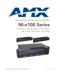
What’s New in X-Series Controllers What’s New in X-Series Controllers Two discrete Network Interfaces (NICs) The NX-2200, NX-3200 and NX-4200 controllers have two 10/100BaseT Ethernet connections. The first, designated as LAN, is intended for connection to the Data Network for external network communications such as database access or scheduling. The second, the ICSLAN is intended for communication with AV devices. These two Ethernet interfaces occupy separate logical address spaces and are implemented as discrete and independent NICs to the microprocessor. There is no IP routing functionality, so there is no ability to port-forward between interfaces. The only built-in communication between these two Ethernet interfaces is via AMX’s ICS protocol, which is accomplished at the application layer. This allows for connection to and configuration of AMX devices on the ICSLAN using Netlinx Studio or RPM Loader from the enterprise network. This is the same mechanism that allows communication with AxLink devices from an Ethernet connection. In addition, a NetLinx or Java application can open independent sockets on these two Ethernet interface and use these sockets to pass data between networks. No other data is able to pass between the interfaces. Using the ICSLAN network The default IP address for the ICSLAN network is 198.18.0.1 with a subnet mask of 255.255.0.0. It is important that the ICSLAN and LAN subnets do not overlap. If the LAN port is configured such that it’s address space overlaps with the ICSLAN network, the ICSLAN network will be DISABLED. DHCP Server The ICSLAN port has a built-in DHCP server. This DHCP server is enabled by default and will serve IP addresses to any connected devices set to DHCP mode. The DHCP server can be disabled from telnet with the command: SET ICSLAN The DHCP address range is fixed. The server will provide addresses in the range x.x.0.2 through x.x.63.255. Devices using static IP addresses on the ICSLAN network should be set within the reserved static IP address range of x.x.64.1 to x.x.255.255. Opening LAN and ICSLAN sockets from code When opening sockets from NetLinx or Java code there is no mechanism to indicate which network to use. The controller will open the socket on whichever network has an IP subnet that matches the address provided in the command to open the socket. There is no indication which network was used, only whether the socket was created successfully. Automatic binding of AMX devices on ICSLAN When an ICSLAN device, such as an EXB-COM2, is set to NDP connection mode (the factory default), it will automatically be bound to the master when connected to it’s ICSLAN port if it’s IP address is valid for the ICSLAN subnet. If the controller is set to serve DHCP addresses on ICSLAN and the ICSLAN device is set to DHCP addressing mode, a valid IP address is assured. Since these are the factory default settings for these devices, automatic binding is the expected behavior for all new equipment. Even after being automatically bound to a master in this manner, if the ICSLAN device is disconnected and moved to the ICSLAN port of a different controller, it’s old binding will be forgotten and it will bind to the new controller to which it’s been connected. Once bound, the device ID still must be set to match the device definition in code. Once bound, the device can also be configured for a different connection mode if desired. What’s New in X-Series Controllers 1 What’s New in X-Series Controllers Support for IPv6 networks The NX-Series controllers fully support IPv6 network addressing. If the LAN port is connected to an IPv6 capable network it will self select an appropriate IPv6 address based on the discovered address parameters of the network to which it’s attached. The controllers simultaneously support IPv4 network addressing. This means any controller may have more than one valid IP address; one IPv4 and one or more IPv6 addresses. When opening sockets from NetLinx or Java code there is no unique command to indicate that you are providing an IPv4 or IPv6 network address. As long as the provided IP address is a valid IPv4 or IPv6 address, the controller will utilize the correct addressing protocol automatically. Link-Local fallback in DHCP mode When the X-Series controller’s LAN IP addressing mode is set to DHCP it will attempt to acquire an IPv4 address from a DHCP server for approximately one minute after boot. If the controller does not receive a valid DHCP address in that time (e.g. if a DHCP server is not found), it will fall back to an IPv4 address in the link-local range. NOTE: Link-local is not an operational mode for the controller; it is a temporary addressing scheme to permit access over the network so that IP settings can be modified. DO NOT commission the controller with a link-local IP address. The default link-local address is 169.254.x.y, where x and y are the least significant two octets of the MAC address. The controller will first verify that this address is not taken by another device on the network. If the address is taken, the controller uses a standard algorithm to find an available IP address in the link-local range. When the controller is using a link-local IP address the status light will blink once per second. If the controller’s network settings remain in DHCP mode it will attempt to acquire a DHCP address every five minutes until it is successful. After each failed attempt to acquire a DHCP address the controller will execute the link-local algorithm and MAY NOT fall back to the same link-local IP address. Wired 802.1X support The X-Series controllers support 802.1X, an IEEE Standard for Port-based Network Access Control. The X-Series controller will act as a supplicant (client device) to an 802.1X enabled network and will present customer provided X.509 certificates to be allowed access to protected networks. ID Pushbutton functionality The X-Series controllers include new ID pushbutton functionality originally implemented on the EXB series of ICSLAN device control modules. Static/DHCP: If the ID button is pressed and held for 10 seconds or longer and then released, the unit toggles between static and dynamic IP addressing. The controller will automatically reboot to complete the process. The default static IP address is 192.168.1.3 with a 255.255.255.0 subnet mask. Factory Reset: If the ID button is held for 10 seconds or longer during the boot process, the unit will reset to factory defaults. This includes resetting the static IP address to its default and deleting the NetLinx program. Factory Image: If the ID pushbutton is held for 20 seconds and released while the unit is booting up, the unit will restore itself to a factory firmware image. This also deletes all code and IRL files. Serial ports differences Unlike current NI controllers, not all serial ports on the X-series controllers support RS-422 and RS-485. The NX-1200 and NX-2200 have one serial port that supports RS-232/422/485, and the NX-3200 and NX-4200 have two. The rest of the serial ports (1 on the NX-1200, 3 on the NX-2200 and 6 on the NX-3200 and NX-4200) support only the RS-232 protocol. All X-Series controllers have screw terminal connectors instead of DB-9 connectors for the serial ports. The RS-232/ 422/485 ports have 10-pin connectors that include all necessary connections for all three protocols in addition to +12V. The ports that support only RS-232 have 5-pin connectors that include Ground, TX, RX, CTS and RTS. 2 What’s New in X-Series Controllers What’s New in X-Series Controllers Serial, IR and AxLink port diagnostics When a string is sent to a serial port or an IR pulse to an IR port, the X-Series controllers can detect and report if the port being used is in a fault condition. The controllers can also detect certain fault conditions on the AxLink bus. The following fault conditions are recognized: The serial cable is not connected The Serial pin is connected to another pin The IR bud is not connected The IR bud is wired backwards One or both AxLink bus data pins are shorted to power or ground On the first attempt to use a port that is in a fault condition, the controller will do the following: Quickly flash the front panel LED of the port being used 10 times Generate an ONERROR data event in NetLinx Report the error to any Duet Module that has claimed the port Report the error to RMS if the controller is connected to an RMS server Set an error flag for that port The status of the error flag can be queried using the GET FAULT NetLinx command, which will result in a DATA EVENT where the return status can be parsed. If the fault condition persists, subsequent attempts to use the same port will only result in the quick flashing of the front panel LED. The ONERROR event and the reporting to a Duet Module or RMS only occur on the first attempt after booting or after the fault status is cleared. This prevents a flood of redundant error messages when a faulted port is used continuously. The fault status is cleared on a successful transmission over the port and can be cleared manually using the CLEAR FAULT NetLinx command. For serial and IR ports, an error condition is only checked at the time the port is used; so unused serial and IR ports will not generate errors. AxLink bus errors are checked at boot time. AxLink power measurement and control IMPORTANT: The NX-Series controllers can NOT be powered via the AxLink port. The +12V pin on the AxLink connectors are designed only for voltage output. Do NOT connect +12V from a power supply or the NXA-PDU to the +12V pin on the AxLink connectors, or you may permanently damage the NX controller and/or the power supply. The AxLink ports on X-Series controller support a new NetLinx command to turn on and off +12V power output on the port. ‘AXPWRON [LOWER/UPPER]’ and ‘AXPWROFF [LOWER/UPPER]’ will turn on and off (respectively) +12V power on the AxLink port. This messages is always sent to port 1 of the 5001 control device and return status will come from the same port. The NX-3200 and NX-4200 both have two AxLink connections. These are two connection points for the same AxLink bus. All AxLink devices connected to the controller must have unique AxLink device numbers even if they are attached to different AxLink connection points on the controller. While it is one AxLink bus, the power on these two AxLink connections is controlled independently. Case Sensitive file system Unlike the NI-Series controllers, all file names on the X-Series controllers are case sensitive. This includes all user files created or used within NetLinx or Java code. If you have legacy code that uses files, it is important that you verify that every reference to each file is consistent with regard to case. If your legacy code generates an error when accessing a file, it is likely due to inconsistent use of case in the filename. What’s New in X-Series Controllers 3 What’s New in X-Series Controllers USB Program port The X-Series controllers utilize a true USB port for configuration and programming via a connected PC. AMX is developing a custom USB driver to support the X-Series controllers, but in the interim we are utilizing a standard PC driver that emulates a COM port. This driver will be installed automatically while installing NetLinx Studio v4.x. Because a PC COM port can only be used by a single process at a time, having a terminal window open using the COM port assigned to that USB connection will prevent any other communication to the controller over that same USB connection, including refreshing the online tree and transferring files. It is recommended that you use the USB programming port to discover the IP address of the controller, modify it if necessary, and then connect over Ethernet to that IP address. USB Firmware upgrade All X-Series controllers support firmware upgrades via a USB solid-state drive. Selecting the desired .kit file and initiating the upgrade are done from telnet. The “IMPORT KIT” telnet command will cause the controller to search the attached USB drive for all valid .kit files and show them as a list. From here you can select the .kit file to use and initiate the firmware upgrade. USB Program download All X-Series controllers support loading NetLinx program files via a USB solid-state drive. Selecting the desired .tkn file and initiating the upload are done from telnet. The “IMPORT TKN” telnet command will cause the controller to search the attached USB drive for all valid .tkn files and show them as a list. From here you can select the .tkn file to use and initiate the program upload. USB logging If a USB storage device is connected via an X-Series controller’s USB port it can be used to store a log of system status messages. Use the “USB LOG” telnet command to enable and disable logging to an attached USB drive. Copy and Clone configuration On any X-Series controller, configuration information can be exported to and imported from a USB storage device. There are two different levels of configuration export, “COPY” and “CLONE”. The “COPY” export is used when the controller being copied from will remain deployed in the system but you wish to copy its security and other configuration settings – but not IP address information – to other Masters. The “CLONE” export is used when the controller being copied from is being removed from the system and replaced by another controller. In addition to the configuration items exported in the “COPY” method, the “CLONE” export also exports IP address information and all code elements. Use the “EXPORT CONFIG” or “EXPORT CLONE” telnet commands to copy or clone the configuration information. Then use the “IMPORT CONFIG” telnet command to load the saved configurations onto a new controller. Difference in DEFINE_PROGRAM program execution Due to differences in the underlying architecture of the X-Series masters, changing variables in the DEFINE_PROGRAM section of code can negatively impact program performance. It has always been considered poor programming practice to change a variable within the DEFINE_PROGRAM section of code. If you have legacy NetLinx code that does change a variable in this section it’s very likely that timing differences will cause your code to run slower and appear less responsive on an X-Series controller. External SD card slot (NX-3200 and NX-4200 only) The external SD card slot in the NX-3200 and NX-4200 is for future use. Until firmware is available that supports the use of an external SD card, the card slot must be left empty. 4 What’s New in X-Series Controllers What’s New in X-Series Controllers Redundant power source (NX-4200 only) The NX-4200 can be powered either with a connection to mains AC power (110/220VAC) or from an external 12V DC power supply. Note: When the NX-4200 is powered only from an external 12V power supply, the ICSLAN ports will still function but they will NOT provide PoE power to connected devices. The NX-4200 can be connected to both mains AC and 12V DC power simultaneously. This provides redundant power for all but PoE power on the ICSLAN ports. If the AC input power is lost or if the internal power supply fails, the NX-4200 will immediately switch to the 12V DC power input without interruption. When AC power is restored, the NX-4200 will switch back to the internal power supply, again without interruption. Power button (NX-4200 only) The NX-4200 includes a momentary button on the front panel that can be used to turn on and off the unit. When power is applied to the unit the power state is always on and the integrated LED is green. If the power button is pressed for more than two seconds while the unit is on, the unit is turned off and the integrated LED changes to amber. Pressing the button momentarily while the unit is off will turn it on and return the integrated LED to green. This is a convenient method for cycling power without unplugging a power connection on the rear of the unit. Note: The power button does not switch off AC power routed to the internal power supply. If AC power is used on the unit, AC power will still be present on the power supply AC input connections even when the unit is turned off. If an internal power fault is detected, the LED integrated into the power button will flash yellow. This is an indication that the unit requires service. Front panel LCD status display (NX-4200 only) The NX-4200 includes a 2-line by 20-character display on the front panel to display status information. The toggle switch next the display scrolls through a fixed list of information about the unit and its current configuration. Included in the list are: Unit serial number and firmware versions LAN port IPv4/IPv6 address(es), MAC address and DNS information ICSLAN port IPv4/IPv6 address(es) and MAC address ICSLAN port PoE status 4-Port PoE ICSLAN switch (NX-4200 only) The NX-4200 includes four ICSLAN connection ports via a built-in 4-port switch. When powered by an AC source, the NX-4200 can supply power via PoE to each port on the 4-port switch. The NX-4200 supports hi-powered PoE (802.3at STANDARD), but the total power draw of all four ports cannot exceed 72 watts. Power can be individually switched off and on to each port from NetLinx code using the “SET POWER ON” and “SET POWER OFF” commands. What’s New in X-Series Controllers 5 What’s New in X-Series Controllers New NetLinx Commands RS232 FAULT COMMANDS: (PORTS 1-8) 'SET FAULT DETECT ON' Enables fault detection on the port (default setting) 'SET FAULT DETECT OFF' Disables fault detection on the port 'CLEAR FAULT' Forces reset back to normal status 'GET FAULT' Responds with one of the following: 'DISABLED', 'NONE', or 'NO DEVICE' 'GET STATUS' Responds with either "STATUS: NORMAL" or "STATUS: FAULT" IR TX FAULT COMMANDS: (PORTS 11-18) 'SET FAULT DETECT ON' Enables fault detection on the port (default setting) 'SET FAULT DETECT OFF' Disables fault detection on the port 'CLEAR FAULT' Forces reset back to normal status 'GET FAULT' Responds with one of the following: 'DISABLED', 'NONE', or 'NO DEVICE' 'GET STATUS' Responds with either "STATUS: NORMAL" or "STATUS: FAULT" PoE COMMANDS (PORT 24-27) 'SET FAULT DETECT ON' Enables fault detection on the port (default setting) 'SET FAULT DETECT OFF' Disables fault detection on the port 'GET FAULT' Responds with one of the following: 'DISABLED', 'NONE', 'UNDER-VOLTAGE / OVER-VOLTAGE', 'CURRENT OVERLOAD', 'LOAD DISCONNECT', 'MAX POWER EXCEEDED', or 'POE NOT AVAILABLE' 'GET STATUS' Responds with either "STATUS: NORMAL" or "STATUS: FAULT" 'SET POWER ON' Enables PoE to the port (default) 'SET POWER OFF' Disables PoE to the port 'GET CLASS' Responds with either 'DISABLED', 'NO DEVICE', or 'CLASS x DEVICE' (x=0 to 4) 'GET VOLTAGE' Responds with number in Volts (typically this is around 55 Volts) 'GET CURRENT' Responds with number in milliAmps RS422/485 (Port 1, Port 5) For the RS-232/422/485 ports a new parameter to the SET BAUD command is required to enable RS-422 mode. The new commands to turn on 422/485 are: ’SET BAUD <baud>,<parity>,<data>,<stop>,[422<ENABLE | DISABLE>]’ ’SET BAUD <baud>,<parity>,<data>,<stop>,[485<ENABLE | DISABLE>]’ ’TSET BAUD <baud>,<parity>,<data>,<stop>,[422<ENABLE | DISABLE>]’ ’TSET BAUD <baud>,<parity>,<data>,<stop>,[485<ENABLE | DISABLE>]’ When 422/485 are disabled, the port operates in 232 mode. Note: To disable both 422 and 485 modes with one command, end the command with 422/485 Disable. AxLink Power and Fault Commands AxLink power can be shut off by command: ‘AXPWRON [LOWER/UPPER]’ ‘AXPWROFF [LOWER/UPPER]’ ‘GET AX FAULT’ The device responds with: AX FAULT: UPPER/LOWER 6 What’s New in X-Series Controllers What’s New in X-Series Controllers New Master Telnet Commands 802.1x wired security > dot1x status|disable|enable Enable/Disable 802.1x security or display current settings. Default is "disable" Firmware Management > manage firmware Answer questions to load previous and factory firmware versions for both master (device 0) and Integrated Device (device 5001). Reboot > reboot <cold|warm> “Cold” reboots the master and restarts the entire operating system “Warm” reboots the master but only starts the AMX NetLinx application firmware Rebootwithnoparameteristhesameas"reboot cold" ICSLAN Settings > set icslan Answer question to set the ICSLAN port settings for hostname, address, and DHCP server. > get icslan Displays the current ICSLAN port settings NetLinx Program execution > program enable|disable|status Enable/disable the NetLinx program or display the status of the current program execution setting. Default is "enabled". Disabling the NetLinx program is the same as flipping dip switch 1. The setting persists until it is manually changed. If the software setting is disabled OR dip switch 1 is "on" then the NetLinx program is disabled. Auto Locate > auto locate enable|disable|status Enable/disable auto locate feature or display status of current setting. Default is "enabled". When the auto locate feature is enabled the master will broadcast its IP information via ICSP for discovery by Modero touch panels. Platform Information > get platform info This command returns the master type, hostname, system number, IPv4 address IPv6 address, MAC address and serial number in a single response. Upgrading, Importing, copying and Logging using USB media > import kit Install a KIT file from USB media. Command will search the media for .kit files and allow the user to select which KIT file to import. > import tkn Install a NetLinx token file from USB media. Command will search the media for .tkn files and allow the user to select which .tkn file to import. > import config Install a previously exported config or clone file. Command will search the media for config and clone .tar files and allow the user to select which file to import > export config to usb front|back Exports a master's configuration to USB media connected to the front or back of the master. This includes security settings, users, groups, tkn file, jar files, IR files. It does not include IP address settings. This is useful when copying configuration settings to other Masters to be used on the same network. > export clone to usb front|back Exports everything included in the export config command with the addition of all IP address settings. This is useful when replacing one Master with another or for duplicating master configurations for testing on a different network. > usb log front|back enable|disable Direct master logs to a USB flash media file. Logs will be named with the current time/date. What’s New in X-Series Controllers 7