1
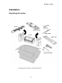
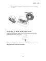
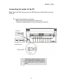
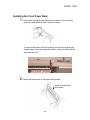
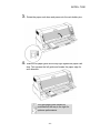
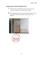
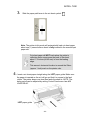
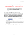
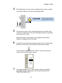
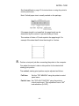
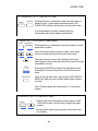
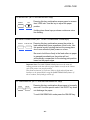
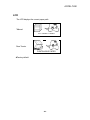
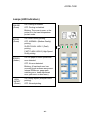
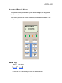
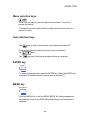
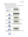
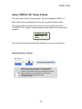
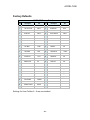
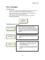
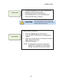
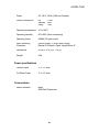
Accel-7450 24-Pin Dot Matrix Printer User’s Guide © April 2012, AMT Datasouth Corp. Document #130090 Copyright Declaration Information in this manual is subject to change without notice and does not represent a commitment on the part of AMT Datasouth Corporation. No part of this manual may be reproduced or transmitted in any form by any means, for any purpose other than the purchaser’s personal use, without the expressed written permission of AMT Datasouth Corporation. Trademark Credits: EPSON is a registered trademark of Seiko Epson Corporation. ESC/P-K2 is a registered trademark of Seiko Epson Corporation. IBM is a registered trademark of International Business Machines Corporation. IBM 2391 is a registered trademark of International Business Machines Corp. OKI is a registered trademark of Oki Data Corporation. OKI 5530SC is a registered trademark of Oki Data Corporation. Windows is a registered trademark of Microsoft Corporation. Regulatory Statement: FCC This device complies with Part 15 of the FCC Rules. Operation is subject to the following two conditions: Class B (1) This device may not cause harmful interference, and (2) this device must accept any interference received, including interference that may cause undesired operation. The manufacturer is not responsible for any radio or TV interference caused by unauthorized modifications to this equipment. Such modifications could void the user’s authority to operate the equipment. - ii - ACCEL- 7450 Table of Contents User Caution...................................................................................................................4 Installation ......................................................................................................................5 Unpacking the printer .................................................................................................................................... 5 Installing the ribbon cassette ......................................................................................................................... 6 Connecting the printer to the power source .................................................................................................. 8 Connecting the printer to the PC ................................................................................................................... 9 Installing the Front Paper Rack ................................................................................................................... 10 Setting up for Cut Sheet Manual mode ....................................................................................................... 12 Special Note for Loading Narrow Cut Sheet Paper ..................................................................................... 14 Special Note for Loading Dark Colored Forms ............................................................................................ 14 Installing the Rear Tractor ........................................................................................................................... 15 Paper Cutter ................................................................................................................................................ 18 Control Panel................................................................................................................ 19 Control Panel Layout ................................................................................................................................... 19 Control Panel Key Functions ....................................................................................................................... 19 LCD .............................................................................................................................................................. 24 Lamps (LED Indicators) ............................................................................................................................... 25 Paper Path Lever ......................................................................................................................................... 26 Head adjustment lever ................................................................................................................................. 27 Special Key Functions ................................................................................................................................. 27 Control Panel Menu ..................................................................................................... 28 Menu key ..................................................................................................................................................... 28 Menu selection keys .................................................................................................................................... 29 Item selection keys ...................................................................................................................................... 29 ENTER key .................................................................................................................................................. 29 MENU key.................................................................................................................................................... 29 Menu Setting Example ................................................................................................................................ 30 Static Ethernet IP Address Setting .............................................................................................................. 31 Using “PWR UP AS” Setup Profiles ............................................................................................................ 32 Factory Defaults........................................................................................................................................... 33 Print Driver Installation ............................................................................................... 34 Problem Solving........................................................................................................... 37 Error messages ............................................................................................................ 41 Printer Specifications .................................................................................................. 44 -3- ACCEL- 7450 Operational safety CAUTION User Caution Do not touch the print head immediately after printing because it is too hot. Do not put your finger under the tractor cover while loading fanfold paper. Cautions in setting up Do not put your finger on the tractor gear, when using the rear tractor. CAUTION Unpack the printer. Make sure that the printer body and all accessories are included in the package and no parts are damaged. Place the printer on a rigid, horizontal base in a location that is free of vibration. Do not use the printer in a location exposed to direct sunlight or close to a heater or other heat generating equipment. Before connecting or disconnecting the interface cable, be sure to turn off the printer. Do not use the printer in a dusty location or any location subject to sudden changes in temperature and humidity. Do not connect the printer to a nonstandard power source. Never try to print without a ribbon cassette installed and paper loaded. Take care not to twist the ribbon while installing the ribbon cassette. If the case or cover becomes dirty, clean it with a soft cloth moistened with a small quantity of neutral detergent diluted with water. Never use a hard cloth or volatile solvent such as alcohol, thinner, or benzene. Do not turn off the printer during printing, as this may lead to a malfunction. Push the lock levers of both tractors to the LOCK positions firmly when loading fanfold paper. -4-4- Rear Operating Clearance Fanfold Paper: 2” plus Paper Length Manual Cut Sheets: Paper Length Minus 9” ACCEL- 7450 Installation Unpacking the printer Tractor USB cable Ribbon cassette Power cable Printer Paper rack Paper rack holder The packing style is subject to change without notice. -5- ACCEL- 7450 Installing the ribbon cassette 1. Make sure the power switch is OFF. Open the front cover. Move the print head to the left end position. CAUTION Do not touch the print head immediately after printing because it may be too hot. 2. For a new printer, remove and discard the clear protective sheet from under the print head. -6- ACCEL- 7450 3. Remove the Red shipping lock located at the center of the ribbon cassette. Attach the cassette, as shown below. 4. Fit the holes in the ribbon attachment to the right and left projections on the print head. • Make sure that the ribbon is located properly under the edge of the print head. -7- ACCEL- 7450 • Turn the ribbon feed knob counterclockwise to remove any slack in the ribbon. Ribbon Feed Knob Connecting the printer to the power source • Make sure that the power switch is set to off. Connect the printer with the supplied power cord to an AC outlet. Connect the AC power plug to an AC outlet of the voltage designated on the rating label located on the back of the printer. -8- ACCEL- 7450 Connecting the printer to the PC Note: The Accel 7450 printer can use a USB, Ethernet or Serial cable to connect to the PC. 1. Install desired interface connection. Make sure that the power switch is turned to off. Connect the signal cable(s) to the printer and the computer. The factory default interface is set to AUTO and will automatically receive transmitted data on any of the above ports. -9- ACCEL- 7450 Installing the Front Paper Rack 1. Insert each (left/right) paper rack arm slot down onto the bottom printer pin and rotate up until it clicks into place. To remove the paper rack, first push up on both the left and right release levers (right lever pictured below), rotate the holder all the way down then lift. 2. Attach the paper rack to the paper rack holders. Install vertically and push down - 10 - ACCEL- 7450 3. Rotate the paper rack down and press onto the rack holder pins. 4. Slide the left paper guide all the way right against the paper rack stop. This squares the left guide and locates the paper edge for auto detection. The right paper guide should be positioned all the way to the right for optimum performance. - 11 - ACCEL- 7450 Setting up for Cut Sheet Manual mode 1. Attach the paper rack holders (right / left) and the paper rack, as described in Installing the Front Paper Rack on page 10. 2. Slide the left paper guide all the way right against the paper rack stop. This squares the left guide and locates the paper edge for auto detection. - 12 - ACCEL- 7450 3. Slide the paper path lever to the cut sheet symbol. Note: The printer in this mode will automatically load cut sheet paper about one (1) second after a sheet is fully inserted in the manual input paper slot. Cut sheet paper will NOT load unless the printer’s reflective photo sensor sees the back of the sheet about 1 ¾ inches (44.45 mm) in from the leading edge. This sensor’s horizontal location is around the 25mm (approx 1 inch) mark on the printer ruler. 4. Insert a cut sheet paper straight along the LEFT paper guide. Make sure the paper is inserted as far as it will go and that it is square to the feed rollers. The printer beeps one time then feeds the sheet in. NOTE: The delay period can be adjusted by setting Control Panel menu item #36 LOAD DELAY. LEFT paper guide - 13 - ACCEL- 7450 Special Note for Loading Narrow Cut Sheet Paper To load cut sheets narrower than 4 ½ inches, disable menu item #25 PAPER SKEW DETECT. Refer to Control Panel operation on page 19 . The SKEW: NO setting can be re-instated by performing an initialization #1(press HIGH IMPACT+LF keys and cycle ON power). Special Note for Loading Dark Colored Forms Excessive top/left margins or paper not loading may be caused by forms with non-reflective or colored areas. Use the special DARK FORM LOAD feature to print such forms. To get started, make sure at least one (1) reflective (white or light colored) form has been loaded and ejected since the printer was last powered up or since the left paper guide was moved. This step sets the left starting print position in the printer’s memory. Press the Fully insert the form into the paper slot until it seats square in the feed rollers BEFORE the printer starts loading. Eject the form and start over if the form is not grasped immediately as the printer will not automatically compensate for the top starting print position. Send the print job. keys. The LCD shows DARK FORM LOAD. Press the ALT+EJECT/LOAD keys again to load each dark form. The printer reverts to normal (white or light colored) paper loading after each load. - 14 - ACCEL- 7450 Installing the Rear Tractor 1. Snap the black plastic paper guides onto the tractor assembly if they are not already in place. The curved ends point away from the printer. 2. Make sure the printer power is off. Plug the cable from the tractor into the connector at the back of the printer. 3. Insert the top slot in the tractor brackets onto the top printer pins. Allow the bottom bracket slots to rest on the bottom printer pins. The tractor brackets do not snap in place. WARNING! Make sure the tractor brackets are fully seated in the bottom pins. Cut sheet forms may jam on the tips of the tractor paper guides if the tractor brackets are not seated. - 15 - ACCEL- 7450 4. Set fanfold paper onto the tractors. Release the lock lever to adjust the tractors right /left to fit the pin feed paper width. CAUTION 5. Do not put your finger under the tractor cover. Use the zero 0 mark on the ruler label attached to the back of the printer as a reference to line up the starting print position by sliding the tractors left or right. Adjust the tractors so the paper is snug between them without tearing or elongating the pin fed holes. 6. To select the rear tractors as the paper feed source, slide the paper path lever on the printer front panel to the rear tractor symbol: Note: The lever position can be at "AUTO" only when using the printer driver to select paper sources. 7. If the paper length is not 11 inches (factory default), specify the appropriate length in the printer’s control panel menu item #6 “TRACTOR PAGE LGTH”. - 16 - ACCEL- 7450 See Control Panel on page 19 for instructions on using the printer’s control panel menu. Note: Fanfold paper size is usually marked on the package If the paper length is not specified, the page length can be determined by the number of sprocket holes per sheet. The number of holes x 0.5 inch equals to the page length. For example if the sheet has 8 holes then length is 4 inches. 8. Perform a test print job after connecting the printer to the computer. Fine adjust the tractor’s side to side position for the desired left starting print position. The vertical, starting print position may be adjusted as follows: Full lines: Set the “TOP MARGIN” using the printer’s control panel menu. Partial Lines: Set “TOF ADJ TRACTOR” using the printer’s control panel menu. This adjustment has a 1/60th inch resolution (0.0166”) - 17 - ACCEL- 7450 Paper Cutter The printer has two (2) cabinet edges where perforated fan fold paper may be separated. Paper cutter Use the front edge when using the rear tractor to feed paper. - 18 - ACCEL-7450 Control Panel The liquid crystal display (LCD) on the control panel displays the current printer status, user messages and menu functions. Control Panel Layout Control Panel Key Functions 1. ONLINE ONLINE JAM REMOVAL The ONLINE key is used to enable printing (ONLINE light ON) or disable printing (ONLINE light OFF). When the light is off, printing is suspended due to a user action (such as pausing the printer) or an error condition (such as a paper out, ribbon problem or paper jam). - 19 - ACCEL-7450 2. EJECT/LOAD EJECT/LOAD DARK FORM If a cut sheet paper is loaded, pressing the EJECT/LOAD key ejects the sheet out the front. If the EJECT/LOAD key is pressed when fanfold paper is loaded, the paper is fed back to the parking position. If the EJECT/LOAD key is pressed when fanfold paper is at the parked position, the paper is loaded to the TOF position. When the EJECT/LOAD key is pressed with no paper in manual load mode, and menu item #25 PAPER SKEW DETECT has been set to YES, AUTO SKEW mode is toggled ON and OFF. Press the ENTER key to activate the displayed mode. 3. SPEED SPEED RESET Press the SPEED key to display the currently selected printing quality on the LCD. Each press of the key displays the printing qualities in the following order. LQ NORMAL HIGH 2 HIGH 1 The factory default value is LQ 4. TEAR OFF TEAR OFF FF Pressing the TEAR OFF key, causes the printer to automatically advance the pin feed paper perforation to the paper cutter position (for fanfold paper only). If the perforation is not adjusted to the cutter position, correct the position with the MICRO LF or MICRO RLF key. The correct position is saved in memory, and the perforation is fed automatically to the paper cutter position at next time. - 20 - ACCEL-7450 5. HIGH IMPACT Press the key to temporarily change the print impact for multipart forms from NORMAL to DARK print mode. The HIGH IMPACT light is ON when DARK print mode is selected. HIGH IMPACT reverts to the current value selected in the printer’s control panel menu settings. The factory default value is NORMAL 6. LF LF MICRO LF 7. ENTER ENTER Press the LF key to feed the line in the forward direction at a pitch of 1/6 inch regardless of the LF PITCH setting in the printer’s control panel menu. Holding this key down produces continuous line feeding. Pressing the ENTER key selects the setting displayed on the LCD. ALT 8. RLF RLF MICRO RLF Pressing the RLF key feeds paper the reverse direction at a pitch of 1/6 inch regardless of the LF PITCH setting in the printer’s control panel menu. Holding this the key depressed produces continuous reverse line feeding. 9. RESET (ALT + SPEED/RESET keys) SPEED ENTER + ALT RESET Pressing the SPEED key while holding the ALT key evokes a power on reset. The LCD displays “INITIALIZING” for a few seconds then returns to ready mode. - 21 - ACCEL-7450 10. FORMFEED ( ALT + TEAR OFF/FF keys) TEAR OFF ENTER + FF ALT Pressing this key combination causes pin feed paper to advance one (1) page length as determined by the PAGE LGTH setting in the printer’s control panel menu. If cut sheet paper is loaded, pressing this key combination causes the paper to be ejected. 11.MENU ( ALT + HIGH IMPACT/MENU keys) HIGH IMPACT ENTER + Pressing this key combination opens the printer’s control panel menu system. MENU ALT LF RLF MICRO LF Once the printer’s menu system is open, menu items may be scrolled with the up and down arrow keys. MICRO RLF The right arrow key opens the displayed menu item. Once opened, the up and down arrow keys scroll through all available choices. TEAR OFF FF Pressing the ENTER key selects the displayed choice. Pressing the left arrow key exits to the top level menu items. HIGH IMPACT MENU Once at the top level menu, pressing the HIGH IMPACT MENU key exits the menu system and evokes a power on reset. Note: Current values are marked with a * in the menu system. 12. MICRO LF (ALT + LF/MICRO LF keys) LF ENTER + ALT Pressing this key combination causes paper to feed 1/360 inch forward. Use this key to adjust the paper position. MICRO LF Holding down these keys produces continuous micro line feeding. - 22 - ACCEL-7450 13. MICRO RLF (ALT + RLF/MICRO RLF keys) RLF ENTER + ALT Pressing this key combination causes paper to reverse feed 1/360 inch. Use this key to adjust the paper position. MICRO RLF Holding down these keys produces continuous micro line feeding. 14. DARK FORMS LOAD (ALT + EJECT LOAD/DARK FORM keys) ENTER EJECT/LOAD + ALT DARK FORM Pressing this key combination causes the printer to load manual feed forms regardless of their color. Use this special mode if printing starts at the wrong place due to non-reflective (dark) areas on a form. Be sure to hold forms firmly in the feed rollers so paper is grasped immediately as the printer will not automatically compensate for the starting print position based on the paper edges. Important Note: The DARK FORMS LOAD feature uses the same left starting position as the last reflective paper load or zero (0) on the cabinet ruler if the printer was just powered up. This means at least one (1) reflective (white or light colored) form must load/eject or be printed before using the DARK FORMS LOAD feature. If this is not done, the left margin will be off. 15. JAM REMOVAL (ALT + ONLINE/JAM REMOVAL keys) ENTER ONLINE + ALT JAM REMOVAL Pressing this key combination allows paper to be easily removed. Use this special mode if the EJECT key does not discharge the paper. To exit JAM REMOVAL mode press the ONLINE key. - 23 - ACCEL-7450 LCD The LCD displays the current paper path. *Manual CUT SHEET PAPER Rear Tractor CONTINUOUS PAPER * Factory default - 24 - ACCEL-7450 Lamps (LED Indicators) ONLINE (Green) ON: Printing is enabled. OFF: Printing is disabled. Blinking: The cover is open, or the printer is in the head temperature protect mode. SPEED (Green) ON: Letter Quality printing. OFF: NORMAL: (Medium Quality) printing. SLOW FLASH: HIGH 1 (Draft) printing FAST FLASH: HIGH 2 (High Speed Draft) printing. ERROR (Amber) ON: No paper or other operational error detected. OFF: No error detected. Blinking: A functional error has occurred (such as home sense error. Internal RAM error, paper path switching error, head adjustment error, park error or skew error). HIGH IMPACT (Green) ON: Heavy impact (multipart forms printing). OFF: Normal printing. - 25 - ACCEL-7450 Paper Path Lever The paper path lever on the left control panel selects the following paper paths. Position Paper path Rear tractor Manual Note: Before changing the paper path, clear the paper from inside the printer by pressing the EJECT/LOAD key. - 26 - ACCEL-7450 Head adjustment lever This lever sets the gap between the print head and the paper. For most printing, the lever position should be to AUTO. This setting allows the printer to measure the paper thickness and adjust the print head gap automatically. The print head gap can also be manually set for 1 to 7 part forms. Special Key Functions Special key functions are executed by pressing and holding the keys indicated in the following table while simultaneously turning on the printer power. Load paper first to avoid error indication. Function Key Initialization #1 HIGH IMPACT + LF+POWER ASCII self-test Hex Dump LF + POWER SPEED + POWER Character H printing mode TEAR OFF + POWER Pin testing Alignments adjust HIGH IMPACT + POWER ENTER + RLF + POWER Adjust the tear off position (For tractor paper) Online state, press and hold the TEAR OFF key three seconds. - 27 - ACCEL-7450 Control Panel Menu The printer’s control panel menu system allows changing the way printer functions work. This section provides the outline of the setup modes and the details of the setup functions. MENU SETUP 1. TOF ADJ MANL 2. TOF ADJ TRAC Menu key ENTER HIGH IMPACT + ALT MENU Press the ALT+ MENU keys to enter the MENU MODE. - 28 - ACCEL-7450 Menu selection keys These keys are used to scroll through the menu items. They do not activate the setting. The menus can be scrolled rapidly by holding down an arrow key for a second or more. Item selection keys The key is used to open a menu item displayed on the LCD. Once opened, the item setting choices may be scrolled with the keys. The key exits to the top level menu without any changes. ENTER key ENTER ALT To select a displayed item, press the ENTER key. When the ENTER key is pressed, the selected item is marked with an asterisk (*). MENU key HIGH IMPACT MENU Press the MENU key to exit the MENU MODE. All setting changes are automatically stored in the EEPROM printer memory and the printer is initialized. - 29 - ACCEL-7450 Menu Setting Example The following is the example to change the page length of fanfold paper from 11 to 8 inch. 1. Press the MENU key while depressing the ALT key. HIGH IMPACT ENTER + MENU ALT MENU SETUP 1. TOF ADJ MANL 2. TOF ADJ TRAC 2. Scroll to item 6 with down arrow key. 6. TRAC PG LGTH 7. RGHT PG WDTH 3. Open item 6 with the right arrow key. 11 INCH 11.5 INCH * 4. Press the up arrow key to display "8 INCH" on the LCD. 8 INCH 8.5 INCH 5. Press the ENTER key. An asterisk is added after "8 INCH". 8 INCH 8.5 INCH * 6. Press the MENU key. The setting is automatically saved and the printer is initialized. - 30 - ACCEL-7450 Static Ethernet IP Address Setting The following steps are required when setting a static IP Ethernet address through the printer control panel menu setup. 1. Press the MENU key while depressing the ALT key. HIGH IMPACT ENTER + MENU ALT MENU SETUP 1. TOF ADJ MANL 2. TOF ADJ TRAC 2. Scroll to item 43 with UP arrow key. 43. IP ADDRESS 44. SUBNET MASK 3. Open item 43 with the right arrow key. IP ADDRESS 010.000.000.001 4. Press the up arrow key to increase (down to decrease) the underlined digit. IP ADDRESS 110.000.000.001 5. Press the right arrow key to select next digit. Repeat steps 4 and 5 until designated IP address is entered. 6. Press the ENTER key after complete address is entered. MENU SETUP 1. TOF ADJ MANL 2. TOF ADJ TRAC 7. Press the MENU key. The setting is automatically saved and the printer is initialized. - 31 - ACCEL-7450 Using “PWR UP AS” Setup Profiles The printer has a total of 6 setup profiles. They are designated USER 1~6. Each profile may be modified with its own set (or group) of setup values. The current profile is selected from the printer’s control panel menu item “41 PWR UP AS” using the same procedure as described in the menu setting example. POWER UP AS USER 1 USER 2 * The printer will use the selected profile whenever it is reset or powered up. Restoring Factory settings: + + Cycle printer power ON USER Settings can be restored to factory default by performing an INTIALIZATION-1. This special key function is executed by pressing and holding these keys while simultaneously turning ON the printer power. Release keys when LCD display reads “EEPROM INITIAL 1”. - 32 - ACCEL-7450 Factory Defaults ACCEL 7450 Factory Defaults Item Description F&I Item Description F&I 1 TOF ADJ MANL 0/60 IN 26 JAM DETECT YES 2 TOF ADJ TRAC 0/60 IN 27 INTERFACE AUTO 3 TOF ADJ DARK 0/60 IN 28 PARITY BIT NONE 4 HORZ ADJ 0/60 IN 29 DATA LENGTH 8 BITS 5 MANL PG LGTH AUTO 30 STOP BIT 1 BIT 6 TRAC PG LGTH 11 INCH 31 PROTOCOL XON/XOFF 7 RGHT PG WDTH NO 32 BAUD RATE 9600 BPS 8 LEFT PG WDTH YES 33 TEXT DIR BI-DIRECT 9 TOP MRG 0 LINE 34 TIMEOUT ON 10 BOTTOM MRG 0 LINE 35 COVER DETECT ON 11 LEFT MRG 0 COL 36 LOAD DELAY 1.0 SEC. 12 FONT SELECT GOTH 37 BEEP ON 13 CHR PITCH 12 CPI 38 TRUNCATE ON 14 LF PITCH 6 LPI 39 QUIET MODE OFF 15 EMULATION F&I 40 TEAR OFF ON 16 CHR TBL EPSN GRAPHICS 41 POWER UP AS USER 1 17 CHR TBL IBM SET 1 42 DHCP ON 18 INTL FONT U.S.A. 43 IP ADDRESS __ 19 CODE PAGE U.S.A. 44 SUBNET MASK __ 20 AGM IBM NO 45 GATEWAY __ 21 LF SETTING LF ONLY 46 MENU LISTING __ 22 CR SETTING CR ONLY 23 ZERO STYLE NO-SLASH 24 MANUAL EJECT FRONT 25 SKEW DETECT NO Settings for User Profiles 2 – 6 are uncontrolled. - 33 - ACCEL-7450 Print Driver Installation Windows (2000,XP,VISTA,WIN7) 1. Select the desired driver provide on the CD ROM shipped with your printer. 2. Open the driver folder and execute “SETUP.exe”, to start the “Printer Installer’ utility. 3. Select the 7450 printer and click the “Install” button. 4. Should a “Windows Security” message appear, select “Install driver software anyway”. - 34 - ACCEL-7450 5. If using a PC/USB interface connection, verify the cable is connected and the printer is turned ON. Click the “Yes” button to continue. If using a PC/USB interface, please connect the printer and computer cable. Cycle printer power ON. With or without the use of a USB interface, click “Yes” to continue. 6. The printer driver installation will take a couple minutes, wait for the “Installation Successful” message to appear and click the “OK” button. The printer driver has been successfully installed! 7. Close driver windows and open “Devices and Printers” from the Start button. - 35 - ACCEL-7450 8. Select 7450 and right click to open Printer Properties, then go to the “Ports” tab and apply the proper port, or create a new port. Refer to the Windows HELP menu for detail instructions. - 36 - ACCEL-7450 Problem Solving 1. Printing misaligns toward the bottom of my form (skews). Ensure the LEFT paper guide is squared by sliding it all the way to the right against the paper rack stop. Take your time in properly aligning the form, being sure to slide it in until it stops against the feed rollers. The printer beeps up to 3 times (default is one beep). 2. Frequent Paper Jams. Flatten any curl at the leading edge of the form by folding it in the opposite direction. The printer will more readily tolerate leading edges that are slightly curled down rather than curled up. Make sure the control panel knob for form thickness is set to AUTO. Excessive paper thickness. Maximum allowable thickness is .020” 3. Printing speed is slow. Press the SPEED key to select a higher speed mode. LQ NORMAL HIGH 2 4. Printing is light. HIGH 1 Check the ribbon cassette condition. If the surface of fabric becomes whitish, replace the cassette with a new one. When using multipart forms: Change SPEED to LQ Press the HIGH IMPACT key to select “DARK”. Make sure carbonless forms have not exceeded their shelf life. Try fresh forms. 5. When menu item #25 PAPER SKEW DETECT is set to YES, (factory default is NO) cut sheet paper is ejected with a SKEW ERROR message on the LCD, even though paper is loaded straight. Dark black areas printed on the paper or the paper is narrower than 4 ½ inches. Set menu item #25 PAPER SKEW DETECT to “NO”. - 37 - ACCEL-7450 6. My printer sometimes asks for a second form when there is none. The printer is misinterpreting left over control characters as more to print. Press the Online key to clear. Press ALT+RESET to clear any pending data. 7. The message PAPER JAM appears, although paper is not jammed. The paper jam sensor on the tractor assembly may not function properly if exposed to direct light or sunlight. Adjust the location of the printer so it is not exposed to excessive light. Verify there is no dark printing near the sprocket hole on the backside of fanfold paper. Set menu item #26 PAPER JAM DETECT to “NO” to defeat paper jam detection. 8. The paper sensor does not detect paper (the print start position is too far down on the paper) or printer will not load paper. If paper is reflective (white or light color), clean paper sensors with a soft cloth or cotton swab. If paper is not reflective (black areas or dark background color), load the paper with the special DARK FORM LOAD feature. Press the ALT+EJECT/LOAD keys. The LCD displays DARK FORM LOAD. Then fully insert the form until it seats in the fee rollers. Paper sensor calibration may be off. Contact AMT Datasouth for assistance. 9. Paper out is not detected. Printing may continue even when paper is out. Make sure the paper size, the page length in the control-panel menu system is correctly set and that the settings are appropriate for the print data. 10. The message "REMOVE PAPER" appears even when the paper is ejected. Clean paper sensors with a soft cloth or cotton swab. Remove any paper particles or fragments from the paper sensors. Contact AMT Datasouth for assistance. 11. Printed vertical lines are not straight. Set menu item # 33 TEXT DIRECTION to “UNI-DIRECT”. - 38 - ACCEL-7450 12. Incorrect characters printed. Wrong emulation. Verify the setting in printer menu item #15 EMULATION is compatible with the print data. The communication connection with the PC may be incorrect. Verify that the correct cable is attached and that is not faulty or broken. Verify communication parameters # 27 to # 32 in the printer’s menu system are properly set. 13. Unexpected margins. Extra or insufficient space between the print start position and the top edge of the paper. Adjust the top margin depending on the paper feed source used by setting parameters # 1 to # 3 TOF ADJUST in the printer’s menu system. Note: Each paper path has its own TOF ADJUST setting. Extra or not enough space between start of printing and the LEFT paper edge. Fine adjustment: Change the left starting position with menu item #4 HORZ ADJ as needed. The total range is ½ inch from -15/60 inch (less margin) to +15/60 inch (more margin). Coarse adjustment: Move the left paper guide further left for more margin. Adjust the paper position by moving the tractors right or left. Note: If you load paper at a new left paper guide position, be sure to load/eject or print at least one (1) reflective (white or light colored) form before using the DARK FORMS LOAD feature. If this is not done, the left margin will be off. The left starting position on the paper for reflective (white or light colored) cut sheet paper remains constant as long as the left paper edge is aligned within 0~15mm mark on the printer ruler. The printer will NOT detect and load cut sheet paper if it is inserted to the right of the 25mm mark on the printer ruler (optical sensor location). 14. Incorrect printing position from the second page of fanfold paper. The page length may be incorrectly set. Set the paper length in item #5 and #6 PAGE LGTH in the printer’s menu system. If using a print driver, check the driver and application paper size settings. - 39 - ACCEL-7450 15. The last characters of a line are printing on the next line below and at the far left of cut sheet forms. Verify menu item # 7 RIGHT PAGE WDTH is set to NO. This is the factory default value. Move the left paper guide so the paper loads further to the left by at least the number of characters printing on the wrong line. Maximum print line width is attained when the left edge of the paper is aligned to approximately 8 mm to the left of the zero (0) position on the ruler molded into printer cabinet. Make sure the line being printed fits within a space of 13.6 inches on the paper. This is as wide as the printer can print. Example: 136 characters maximum at 10cpi or 163 characters maximum at 12cpi. Note. If the paper is too narrow for the data, the printer will print off the right edge of the paper onto the platen. If printing exceeds the rightmost printing capability of the printer (approximately the 340 mm position on the ruler molded into printer cabinet), surplus characters are automatically printed on the next line (the text wraps). 16. Unit continues to print previous job. Press ALT+RESET to clear any pending data. - 40 - ACCEL-7450 Error messages Function errors Function errors indicate a serious problem that cannot be recovered by the user. The printer can report 12 types of functional errors. When a function error occurs, turn the power off, remove paper from inside the printer then turn the printer back on. If the message remains after the above procedure, contact AMT Datasouth for assistance. FUNCTION ERROR 1~12 Operational error message ONLINE lamp blinks. The print head has become too hot during high-density printing. When this message is displayed, printing speed is reduced or printing stops. When the print head temperature drops, the printer resumes normal printing. HEAD PROTECTION PARK ERROR Indicates fanfold paper is not fed back to the parking position properly. Remove and reload paper. Fanfold paper is not loaded in the rear tractor. Install fanfold paper in the rear tractor and press the ONLINE key. A cut sheet is not loaded into the printer. Put a cut sheet on the front rack and load it into the printer. PAPER OUT - 41 - ACCEL-7450 Paper has jamed at tractor. Pull any wrinkled paper out, reload paper in the tractors then press the ONLINE key to restart printing. When the PAPER JAM error message appears despite there being no actual paper jam, set menu #26 PAPER JAM DETECT to NO. A cut sheet did not eject properly. Remove the paper manually. This also naturally occurs at the end of a print job or EJECT/LOAD function and the paper has not yet been removed from the paper rack. PAPER JAM REMOVE PAPER This error occurs if menu item # 25 PAPER SKEW DETECT has been changed to YES and the printer detects that a cut sheet paper is loaded at an angle beyond the printer’s ability to square it. The ERROR lamp blinks, the buzzer sounds three times and the paper is ejected. Reload the paper straight. SKEW ERROR This error also occurs if the paper is loaded straight but is too narrow. • To load cut sheets narrower than 4 ½ inches, verify menu item # 25 PAPER SKEW DETECT has been disabled (set to NO). - 42 - ACCEL-7450 COVER OPEN This error occurs if the front cover is opened and causes the ONLINE lamp to blink. Closing the front cover clears the error. Press the ONLINE key to put the printer back online (ONLINE lamp on steady). CAUTION Never open the front cover during printing. Press the ONLINE key first to stop printing and then open the front cover. The jam sensor is defective. JAM SENSOR Press the ONLINE key to clear the error. Press the EJECT/LOAD key to unload paper as needed. Make sure the jam sensor on the tractor is clear of paper pieces and is clean. Reload fanfold paper. NOTE: The paper jam sensor may not function properly if it is exposed to a direct light or sunlight. Relocate the printer as needed. - 43 - ACCEL-7450 Printer Specifications Printing Method Serial Impact Dot Matrix Flatbed, Straight Paper Path Print Head 24 Pin Max Print Line 13.6” Multipart Printing Up to 7 Part .020” Max Thickness Cut Sheet Loading Automatic Optical Paper Detection Optical Paper Edge Detection Dark Forms Load mode (no paper detection) Paper Paths Rear Tractor Front Cut Sheet Control Panel Selectable Paper Exit Front or Rear Exit Head Gap Adjustment Auto, with Manual Override Interfaces - Auto Switching USB (2.0 Full-Speed) RS232 Serial (9-pin) Ethernet (10/100 Base-T) Input Buffer 64 K Byte Emulations F&I IBM Epson OKI Font Typeface 8 Styles Setup Memory 6 Setup Profiles - 44 - ACCEL-7450 Power AC 120 V, 60Hz (USA and Canada) Power consumption LQ Standby Sleep Operating temperature 41 to 104ºF Operating humidity 40 to 90% (Non condensing) Operating Noise 58dBA (LQ print mode) Rear Operating Clearance Fanfold Paper: 2” plus Paper Length Manual Cut Sheets: Paper Length Minus 9” Dimensions 25”(w) x 18.3”(d) x 11.6”(h) Weight 51lb 110W 40W 14W Paper specifications Fanfold Paper 3” to 15” wide Cut Sheet Paper 2” to 15” wide Consumables Ribbon cassette Black 20M Draft Characters - 45 -