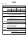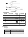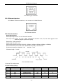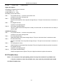
1
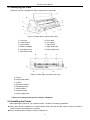
DP750 User's Manual 2.3 Identifying the Parts Figures 2-2 and 2-3 highlight the main components of the printer. A D E 杆 K H B G J F C I Figure 2-3 Main parts of printer (front view) A: Top cover B: Control panel C: Power switch D: Ribbon cartridge E: Gap adjust lever F: Sub friction roller G: Print head H: Front table I: Paper guide J: Paper feed knob K: Paper select lever A C B D H E G F Figure 2-4 Main parts of printer (rear view) A: Tractor B: Paper guide slider C: Tractor D: Ethernet interface E: Parallel interface F: USB interface G: Serial interface H: Power supply inlet Caution: According to the specific interface standards. 2.4 Installing the Printer Before placing the printer in your chosen location, consider the following guidelines: This printer should be placed on a normal table or desk. Be sure that the surface is level; to avoid an uneven load on the carriage as it operates. Do not install the printer where it may be subjected to: -4-