1
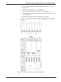
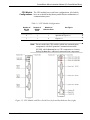
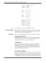
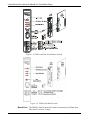
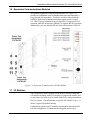
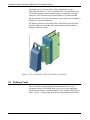
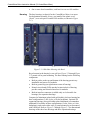
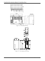
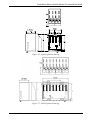
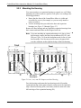
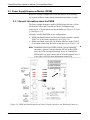
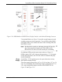
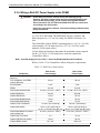
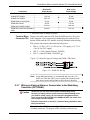
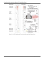
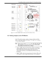
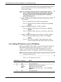
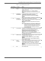
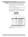
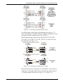
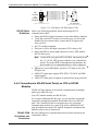
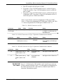
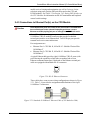
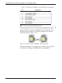
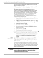
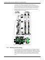
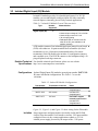
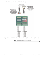
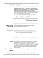
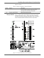
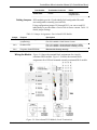
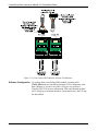
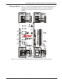
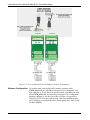
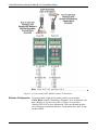
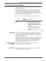
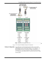
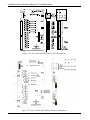
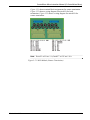
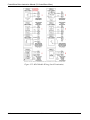
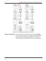
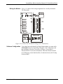
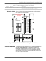
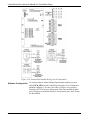
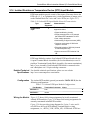
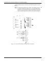
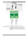
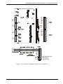
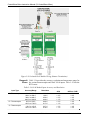
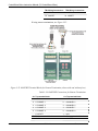
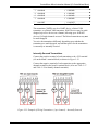
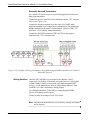
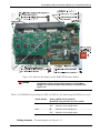
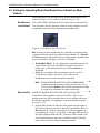
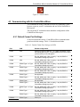
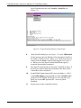
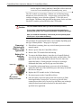
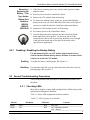
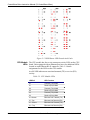
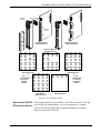
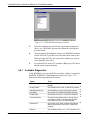
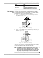
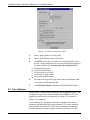
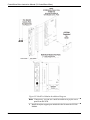
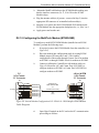
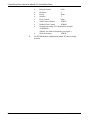
ControlWave Micro Instruction Manual (CI-ControlWave Micro) JP5: Three-position Field Voltage Shutdown Trip Point Selection Jumper o 1-to-2 Installed = +12V Bulk Supply Field Voltage Shutdown Trip Point Selected o 2-to-3 Installed = +24V Bulk Supply Field Voltage Shutdown Trip Point Selected. (default) 2.3.4 Setting Mode Switch SW1 on the PSSM The version of the PSSM shown in Figure 2-10 has a DIP switch that controls whether the PSSM operates in Local Mode or Recovery Mode. Local Mode is the normal operating mode for the ControlWave Micro, and is the factory default. We recommend you use the factory default unless you have a reason to use Recovery Mode. Only use Recovery Mode during system firmware upgrades or core updumps. See Chapter 5 for more information on these subjects. Table 2-1 lists the SW1 settings: Table 2-1. PSSM Switch SW1 Switch position Mode Both switches set to right (Open) or both switches set to left (Closed) Activates Recovery mode, used for firmware upgrades or core updumps. Upper switch (SW-1) set to right Activates Local mode, used for (Open) and lower switch (SW-2) set to normal operation. (This is the factory left (Closed) default) Note: Only the PSSM SW1 switch settings listed in the table have been tested. 2.3.5 General Wiring Guidelines Revised Jun-2013 ControlWave Micro PSSMs use compression-type terminals that accommodate up to #14 AWG wire. When making a connection, insert the bare end of the wire (approx ¼” max) into the clamp adjacent to the screw and secure the wire. To prevent shorts, ensure that no bare wire is exposed. If using standard wire, tin the bare end with solder to prevent flattening and improve conductivity. Allow some slack in the wire while making terminal connections. Slack makes the wires more manageable and helps minimize mechanical strain on the terminal blocks. Installation 2-13