1
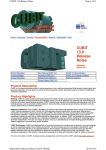
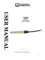
CS526 ISFET ph Probe Issued: 9.6.14 Copyright © 2009-2014 Campbell Scientific, Inc. Printed under licence by Campbell Scientific Ltd. CSL 947 Guarantee This equipment is guaranteed against defects in materials and workmanship. This guarantee applies for six months from date of delivery. We will repair or replace products which prove to be defective during the guarantee period provided they are returned to us prepaid. The guarantee will not apply to: • Equipment which has been modified or altered in any way without the written permission of Campbell Scientific • Batteries • Any product which has been subjected to misuse, neglect, acts of God or damage in transit. Campbell Scientific will return guaranteed equipment by surface carrier prepaid. Campbell Scientific will not reimburse the claimant for costs incurred in removing and/or reinstalling equipment. This guarantee and the Company’s obligation thereunder is in lieu of all other guarantees, expressed or implied, including those of suitability and fitness for a particular purpose. Campbell Scientific is not liable for consequential damage. Please inform us before returning equipment and obtain a Repair Reference Number whether the repair is under guarantee or not. Please state the faults as clearly as possible, and if the product is out of the guarantee period it should be accompanied by a purchase order. Quotations for repairs can be given on request. It is the policy of Campbell Scientific to protect the health of its employees and provide a safe working environment, in support of this policy a “Declaration of Hazardous Material and Decontamination” form will be issued for completion. When returning equipment, the Repair Reference Number must be clearly marked on the outside of the package. Complete the “Declaration of Hazardous Material and Decontamination” form and ensure a completed copy is returned with your goods. Please note your Repair may not be processed if you do not include a copy of this form and Campbell Scientific Ltd reserves the right to return goods at the customers’ expense. Note that goods sent air freight are subject to Customs clearance fees which Campbell Scientific will charge to customers. In many cases, these charges are greater than the cost of the repair. Campbell Scientific Ltd, Campbell Park, 80 Hathern Road, Shepshed, Loughborough, LE12 9GX, UK Tel: +44 (0) 1509 601141 Fax: +44 (0) 1509 601091 Email: [email protected] www.campbellsci.co.uk PLEASE READ FIRST About this manual Please note that this manual was originally produced by Campbell Scientific Inc. primarily for the North American market. Some spellings, weights and measures may reflect this origin. Some useful conversion factors: Area: 1 in2 (square inch) = 645 mm2 Length: 1 in. (inch) = 25.4 mm 1 ft (foot) = 304.8 mm 1 yard = 0.914 m 1 mile = 1.609 km Mass: 1 oz. (ounce) = 28.35 g 1 lb (pound weight) = 0.454 kg Pressure: 1 psi (lb/in2) = 68.95 mb Volume: 1 UK pint = 568.3 ml 1 UK gallon = 4.546 litres 1 US gallon = 3.785 litres In addition, while most of the information in the manual is correct for all countries, certain information is specific to the North American market and so may not be applicable to European users. Differences include the U.S standard external power supply details where some information (for example the AC transformer input voltage) will not be applicable for British/European use. Please note, however, that when a power supply adapter is ordered it will be suitable for use in your country. Reference to some radio transmitters, digital cell phones and aerials may also not be applicable according to your locality. Some brackets, shields and enclosure options, including wiring, are not sold as standard items in the European market; in some cases alternatives are offered. Details of the alternatives will be covered in separate manuals. Part numbers prefixed with a “#” symbol are special order parts for use with non-EU variants or for special installations. Please quote the full part number with the # when ordering. Recycling information At the end of this product’s life it should not be put in commercial or domestic refuse but sent for recycling. Any batteries contained within the product or used during the products life should be removed from the product and also be sent to an appropriate recycling facility. Campbell Scientific Ltd can advise on the recycling of the equipment and in some cases arrange collection and the correct disposal of it, although charges may apply for some items or territories. For further advice or support, please contact Campbell Scientific Ltd, or your local agent. Campbell Scientific Ltd, Campbell Park, 80 Hathern Road, Shepshed, Loughborough, LE12 9GX, UK Tel: +44 (0) 1509 601141 Fax: +44 (0) 1509 601091 Email: [email protected] www.campbellsci.co.uk Precautions DANGER — MANY HAZARDS ARE ASSOCIATED WITH INSTALLING, USING, MAINTAINING, AND WORKING ON OR AROUND TRIPODS, TOWERS, AND ANY ATTACHMENTS TO TRIPODS AND TOWERS SUCH AS SENSORS, CROSSARMS, ENCLOSURES, ANTENNAS, ETC. FAILURE TO PROPERLY AND COMPLETELY ASSEMBLE, INSTALL, OPERATE, USE, AND MAINTAIN TRIPODS, TOWERS, AND ATTACHMENTS, AND FAILURE TO HEED WARNINGS, INCREASES THE RISK OF DEATH, ACCIDENT, SERIOUS INJURY, PROPERTY DAMAGE, AND PRODUCT FAILURE. TAKE ALL REASONABLE PRECAUTIONS TO AVOID THESE HAZARDS. CHECK WITH YOUR ORGANIZATION'S SAFETY COORDINATOR (OR POLICY) FOR PROCEDURES AND REQUIRED PROTECTIVE EQUIPMENT PRIOR TO PERFORMING ANY WORK. Use tripods, towers, and attachments to tripods and towers only for purposes for which they are designed. Do not exceed design limits. Be familiar and comply with all instructions provided in product manuals. Manuals are available at www.campbellsci.eu or by telephoning +44(0) 1509 828 888 (UK). You are responsible for conformance with governing codes and regulations, including safety regulations, and the integrity and location of structures or land to which towers, tripods, and any attachments are attached. Installation sites should be evaluated and approved by a qualified engineer. If questions or concerns arise regarding installation, use, or maintenance of tripods, towers, attachments, or electrical connections, consult with a licensed and qualified engineer or electrician. General • Prior to performing site or installation work, obtain required approvals and permits. Comply with all governing structure-height regulations, such as those of the FAA in the USA. • Use only qualified personnel for installation, use, and maintenance of tripods and towers, and any attachments to tripods and towers. The use of licensed and qualified contractors is highly recommended. • Read all applicable instructions carefully and understand procedures thoroughly before beginning work. • Wear a hardhat and eye protection, and take other appropriate safety precautions while working on or around tripods and towers. • Do not climb tripods or towers at any time, and prohibit climbing by other persons. Take reasonable precautions to secure tripod and tower sites from trespassers. • Use only manufacturer recommended parts, materials, and tools. Utility and Electrical • You can be killed or sustain serious bodily injury if the tripod, tower, or attachments you are installing, constructing, using, or maintaining, or a tool, stake, or anchor, come in contact with overhead or underground utility lines. • Maintain a distance of at least one-and-one-half times structure height, or 20 feet, or the distance required by applicable law, whichever is greater, between overhead utility lines and the structure (tripod, tower, attachments, or tools). • Prior to performing site or installation work, inform all utility companies and have all underground utilities marked. • Comply with all electrical codes. Electrical equipment and related grounding devices should be installed by a licensed and qualified electrician. Elevated Work and Weather • Exercise extreme caution when performing elevated work. • Use appropriate equipment and safety practices. • During installation and maintenance, keep tower and tripod sites clear of un-trained or non-essential personnel. Take precautions to prevent elevated tools and objects from dropping. • Do not perform any work in inclement weather, including wind, rain, snow, lightning, etc. Maintenance • Periodically (at least yearly) check for wear and damage, including corrosion, stress cracks, frayed cables, loose cable clamps, cable tightness, etc. and take necessary corrective actions. • Periodically (at least yearly) check electrical ground connections. WHILE EVERY ATTEMPT IS MADE TO EMBODY THE HIGHEST DEGREE OF SAFETY IN ALL CAMPBELL SCIENTIFIC PRODUCTS, THE CUSTOMER ASSUMES ALL RISK FROM ANY INJURY RESULTING FROM IMPROPER INSTALLATION, USE, OR MAINTENANCE OF TRIPODS, TOWERS, OR ATTACHMENTS TO TRIPODS AND TOWERS SUCH AS SENSORS, CROSSARMS, ENCLOSURES, ANTENNAS, ETC. Contents PDF viewers: These page numbers refer to the printed version of this document. Use the PDF reader bookmarks tab for links to specific sections. 1. Introduction ................................................................. 1 2. Cautionary Statements............................................... 1 3. Initial Inspection ......................................................... 1 4. Quickstart .................................................................... 2 4.1 4.2 Preparation for Use and Installation ..................................................... 2 Use SCWin to Program Datalogger and Generate Wiring Diagram .... 2 5. Overview ...................................................................... 5 6. Specifications ............................................................. 5 7. Operation ..................................................................... 6 7.1 7.2 Wiring .................................................................................................. 6 Datalogger Programming ..................................................................... 6 7.2.1 Get Data Command....................................................................... 6 7.2.2 CRBasic Instruction Sequence ...................................................... 7 7.2.3 Instruction Descriptions ................................................................ 7 7.2.3.1 SerialOpen() Instruction ..................................................... 7 7.2.3.2 SerialOut() Instruction........................................................ 8 7.2.3.3 SerialIn() Instruction .......................................................... 8 7.2.3.4 SplitStr() Instruction ........................................................... 9 7.2.4 Programming for Calibration ........................................................ 9 7.3 Calibration ............................................................................................ 9 8. Troubleshooting ......................................................... 9 9. Maintenance .............................................................. 10 9.1 Cleaning ............................................................................................. 10 9.1.1 When to Clean............................................................................. 10 9.1.2 Cleaning Procedure ..................................................................... 11 9.1.2.1 Cleaning Tips ................................................................... 11 9.1.3 Revitalizing ................................................................................. 12 9.2 Storage ............................................................................................... 12 9.2.1 Short-Term Storage (2 days or less)............................................ 12 9.2.2 Long-Term Storage (more than 2 days) ...................................... 12 i Appendices A. Importing Short Cut Code ...................................... A-1 A.1 Importing Short Cut Code into a Program Editor ............................A-1 B. Example Program ................................................... B-1 C. Calibration ............................................................... C-1 C.1 Example Calibration Program .......................................................... C-2 9-1. Tip of the CS526 probe ...................................................................... 11 7-1. 7-2. 7-3. 7-4. Wiring .................................................................................................. 6 “Get Data” Command and Response ................................................... 7 Instruction Sequence ............................................................................ 7 Calibration Standards ........................................................................... 9 Figures Tables ii CS526 ISFET pH Probe 1. Introduction The CS526 ISFET pH Probe measures pH from 2 to 12 in aqueous or semi-solid solutions. It outputs TTL serial data that is read by compatible dataloggers (see Section 6, Specifications). Before using the CS526, please study • • • Section 2, Cautionary Statements Section 3, Initial Inspection Section 4, Quickstart More detailed instructions for operation, troubleshooting, and maintenance are available in the remaining sections. 2. 3. Cautionary Statements • READ AND UNDERSTAND the Precautions section at the front of this manual. • Campbell Scientific warranty does not cover a clogged reference diaphragm or improperly cleaned or maintained ISFET chip (see Section 9, Maintenance). • Maximum input voltage is 5 Vdc. Incorrect wiring may cause performance loss and irreversible damage. • To prevent scratching the sensor chip when cleaning, first soak the sensor in soapy water and then gently scrub with a toothbrush (see Section 9, Maintenance). Most scratches occur when hard particles are rubbed on the chip surface. Scratches cause irreversible damage to the probe. • Do not use hydrofluoric acid, acetone, MEK, or similar agents to clean the probe. • Cable can be damaged by abrasion, rodents, sharp objects, twisting, crimping or crushing, and pulling. Take care during installation and use to avoid cable damage. • The CS526 is rugged, but it should be handled as a precision scientific instrument. • The CS526 has no user-serviceable parts. Any attempt to disassemble the device will void the six-month warranty. • Care should be taken when opening the shipping package to not damage or cut the cable jacket. If damage to the cable is suspected, consult with a Campbell Scientific application engineer. Initial Inspection Upon receipt of the CS526, inspect the packaging and contents for damage. File damage claims with the shipping company. 1 CS526 ISFET pH Probe The model number and cable length are printed on a label at the connection end of the cable. Check this information against the shipping documents to ensure the correct product and cable length are received. 4. Quickstart For complete installation, programming, and calibration information, see Sections 7.1 through 7.3. 4.1 Preparation for Use and Installation 1. Soak the CS526 in 7-pH buffer solution for 15 minutes. 2. Follow the calibration procedure outlined in Appendix C, Calibration. 3. Place the CS526 in the liquid being measured. The CS526 ISFET pH probe can be installed without regard to orientation. NOTE 4.2 When installing in a well, the #7421 Split Mesh Cable grip is recommended to centre and suspend the cable, reducing cable stretch. Use SCWin to Program Datalogger and Generate Wiring Diagram Short Cut is an easy way to program your datalogger to measure the CS526 and assign datalogger wiring terminals. The following procedure shows using Short Cut to program the CS526. 2 1. Install Short Cut by clicking on the install file icon. Get the install file from either www.campbellsci.com, the ResourceDVD, or find it in installations of LoggerNet, PC200W, PC400, or RTDAQ software. 2. The Short Cut installation should place a Short Cut icon on the desktop of your computer. To open Short Cut, click on this icon. User Manual 3. When Short Cut opens, select New Program. 4. Select Datalogger Model and Scan Interval (default of 5 seconds is OK for most applications). Click Next. 3 CS526 ISFET pH Probe 5. Under the Available Sensors and Devices list, select the Sensors | Water | Quality folder. Select CS526 ISFET pH Probe. Click selection to the Selected device window. 4 to move the 6. After selecting the sensor, click at the left of the screen on Wiring Diagram to see how the sensor is to be wired to the datalogger. The wiring diagram can be printed out now or after more sensors are added. 7. Select any other sensors you have, then finish the remaining Short Cut steps to complete the program. The remaining steps are outlined in Short Cut Help, which is accessed by clicking on Help | Contents | Programming Steps. User Manual 5. 8. If LoggerNet, PC400, or PC200W is running on your PC, and the PC to datalogger connection is active, you can click Finish in Short Cut and you will be prompted to send the program just created to the datalogger. 9. If the sensor is connected to the datalogger, as shown in the wiring diagram in step 6, check the output of the sensor in the datalogger support software data display to make sure it is making reasonable measurements. Overview The CS526 uses SENTRON’s high-tech, Ion Sensitive Field Effect Transistor (ISFET) semi-conductor as its pH-sensitive element, and includes a silver/silver chloride – potassium chloride reference system. The CS526’s design allows it to be suitable for a variety of liquid pH-monitoring applications. Its electronics are safely embedded in a durable PEEK body. Elimination of the glass-bulb removes the possibility of broken glass, making the CS526 more rugged and safer to use. NOTE 6. The CS526 is shipped dry and therefore must be soaked in pH solution before use. Specifications Features: • Safety — the ISFET with durable PEEK material can be used safely in applications where broken glass is a hazard to the user. • Intelligent electronics — the CS526 combines the latest developments in ISFET pH sensing technology with state-of-the-art signal processing. This allows for accurate, fast and reliable results. • Quality — designed and manufactured under stringent quality control conditions in an ISO 9001 environment. Each sensor is individually tested to the most demanding testing protocols, and the electronics comply fully with directives and with EMC standard IEC61326:2005. • Compatible with Campbell Scientific CRBasic dataloggers: CR800 series, CR1000, and CR3000. Measurement Range: Accuracy: 24 hr drift: 2 to 12 pH ±0.2 pH with 2-point calibration <0.15 pH (after 15-min soak in pH 7 at 25°C) Operating Temperature: Water Pressure: 10° to 40°C 0 to 700 kPa (0 to 101.5 psi) Power Requirement Source: Load: 5 Vdc 15 mA maximum Output: TTL logic, 2400 bps 8 data bits, no parity, 1 stop bit Maximum Cable Length: 100 m (328 ft) Cable Type: Three-twisted pair, 24-AWG cable with Santoprene jacket 5 CS526 ISFET pH Probe Sensor Material: PEEK Weight w/10-ft cable: 318 g (11.2 oz) Dimensions Length: Diameter: 102 mm (4 in) 16 mm (0.63 in) Certifications: 7. ISO 9001 compliant EMC standard IEC61326:2005 Operation If you are programming your datalogger with Short Cut, skip Section 7.1, Wiring, and Section 7.2, Datalogger Programming. Short Cut does this work for you. See Section 4, Quickstart, for a Short Cut tutorial. 7.1 Wiring Table 7-1. Wiring CAUTION 7.2 Wire Colour Wire Label/Function Datalogger Connections Red (see following caution) Power 5V 5V Black Ground G White Signal #1 (Rx) Control Port (Tx) Green Signal #2 (Tx) Control Port (Rx) Clear Shield G This probe must be connected to the datalogger’s 5 V terminal (not 12 V). Connecting to a higher voltage will damage the probe beyond repair. Datalogger Programming 7.2.1 Get Data Command The datalogger needs to send a “get data” serial command to the CS526 to get the pH data. This command is sent to the CS526 via the SerialOut() CRBasic instruction (see Section 7.2.3.2, SerialOut() Instruction). Table 7-2 shows the “get data” command and its response. 6 User Manual Table 7-2. “Get Data” Command and Response Command Response aMn!<CR> a<value><CR><LF> Where: a = probe address (factory default is 1) n = a single dummy character (typically use 1) Where: a = probe address (factory default is 1) <value> = the probe’s reading for pH (in digital counts). 7.2.2 CRBasic Instruction Sequence A sequence of CRBasic instructions is used to measure the sensor. Table 7-3 shows the instruction sequence. Information about the instructions is provided in Section 7.2.3, Instruction Descriptions, and an example program is provided in Appendix B, Example Program. Table 7-3. Instruction Sequence NOTE Instruction Function SerialOpen() Set up a datalogger port for serial communication (see Section 7.2.3.1, SerialOpen() Instruction) Scan() Establish a scan rate SerialOut() Send “get data” command to the CS526. See Section 7.2.1, Get Data Command, and 7.2.3.2, SerialOut() Instruction, for more information. SerialIn() Set up the COM port to receive the incoming serial data (see Section 7.2.3.3, SerialIn() Instruction). Please note that in the beginning of the CRBasic program, the variable used in the SerialIn() instruction needs to be declared as an ASCII string format. SplitStr() Split out digital count value for pH from the input string. Probe output is “Counts”. A corrected multiplier and offset are required to provide an output in pH units (see Appendix C, Calibration). 7.2.3 Instruction Descriptions 7.2.3.1 SerialOpen() Instruction The SerialOpen() instruction has the following syntax: SerialOpen(ComPort,BaudRate,Format,TXDelay,BufferSize) ComPort — the datalogger COM port in which the probe is connected. BaudRate — choose 2400 Format — choose 16, which is TTL Logic; No parity, one stop bit, 8 data bits; No error checking TXDelay — enter 0 BufferSize — enter at least twice the number of maximum expected characters + 1, which is 41. 7 CS526 ISFET pH Probe 7.2.3.2 SerialOut() Instruction The SerialOut() instruction has the following syntax: SerialOut(ComPort,OutString,WaitString,NumberTries,TimeOut) ComPort — the datalogger COM port in which the probe is connected. OutString — use "1M1!"+CHR(13) for the OutString when the default probe address of 1 is used. WaitString — enter the null (“”) WaitString to tell the datalogger to wait for the echo of each character in the OutString NumberTries — enter 0 TimeOut — specifies the time, in 0.01 seconds, that the datalogger should wait for the WaitString or echo of each character in the OutString (0 is used in the example program). 7.2.3.3 SerialIn() Instruction The SerialIn() instruction has the following syntax: SerialIn(Dest,ComPort,TimeOut,TerminationChar,MaxNumChars) Dest — specifies the variable in which the incoming data will be stored. Please note that in the beginning of the CRBasic program, this variable needs to be declared as ASCII string format (see example program in Appendix B, Example Program) ComPort — the datalogger COM port in which the probe is connected. TimeOut — 20 should be adequate, which gives a 200 ms maximum delay time. The TimeOut parameter is used to specify the amount of time, in 0.01 seconds, that the datalogger should wait before proceeding to the next instruction. TerminationChar — enter 0 MaxNumChars — 20 should be adequate (specify the maximum number of characters to expect per input) 8 User Manual 7.2.3.4 SplitStr() Instruction The SplitStr() instruction has the following syntax: SplitStr(SplitResult,SearchString,FilterString,NumSplit,SplitOption) SplitResult — an array in which the split string will be stored. SearchString — the string on which this instruction will operate. This will be the variable entered for the Dest parameter for the SerialIn() instruction (see above). FilterString — enter “String” (this value will be ignored because of the SplitOption that will be used). NumSplit — enter 2 SplitOption — enter 0. This splits out numeric values. 7.2.4 Programming for Calibration To output in pH units instead of digital counts, enter the offset and multiplier into the datalogger program. Simple program instructions can be used to make the required periodic calibration easier. See Appendix C, Calibration, for an example program. 7.3 Calibration Calibration should be carried out according to the detailed procedure outlined in Appendix C, Calibration. The calibration should use two or more pH standards, listed in Table 7-4, which are available from Campbell Scientific. Table 7-4. Calibration Standards pH Part Number 4 #25587 7 #25586 10 #25588 Frequency of calibration depends on the level of accuracy required and the coating / fouling nature of the measured samples. 8. Troubleshooting NOTE Contact Campbell Scientific if the CS526 is not operating properly and requires return to Campbell Scientific Ltd. The most common causes for erroneous pH data include: • poor sensor connections to the datalogger • damaged cables • scratched chip • contaminated or clogged diaphragm 9 CS526 ISFET pH Probe Problem: Output signal is at its maximum value. Possible reasons: o Probe is not in fluid. o Chip is polluted. o Diaphragm is polluted. o Chip is scratched. Suggestions: o Put probe in fluid. o Clean probe (Section 9.1, Cleaning). o Probe cannot be fixed if chip is scratched. Problem: Probe response is very slow. Possible reason: o Diaphragm is chipped or polluted. Suggestion: o Clean probe (Section 9.1, Cleaning). Problem: Probe signal is drifting. Possible reasons: o Diaphragm can be dried out. o Chip is scratched. Suggestions: o Soak probe for 10 minutes in saturated KCl solution (pn #16349). o Probe cannot be fixed if chip is scratched. 9. Maintenance CAUTION The CS526 needs to be periodically cleaned and calibrated to ensure accurate readings and proper operation. The CS526 has no user-serviceable parts. 9.1 Cleaning Proper maintenance of a probe is important. If the probe is not properly and regularly cleaned, the probe can malfunction due to a contaminated diaphragm or ISFET chip. Contamination on/or blockage of the sensor and reference electrode diaphragm surface is the most likely cause for probe failure. Probe wear is another cause for probe failure. Probe wear is often, but not necessarily, preceded by a period of declining calibration slope values. Probe wear is dependent on how the probe is used and stored (see Section 9.2, Storage). Worn probes need to be replaced. 9.1.1 When to Clean Often the probe should be cleaned daily, but the appropriate cleaning frequency is dependent on the type of sample being measured. Clean the probe if any of the following occur: • • 10 Low slope Drift User Manual • • • • Instability of the reading Slow calibration Probe will not calibrate pH value doesn’t change as expected when changing samples Additionally, when sampling coloured liquids, the probe should be cleaned when the reference diaphragm is no longer white. 9.1.2 Cleaning Procedure Read Section 9.1.2.1, Cleaning Tips, before following this procedure. CAUTION 1. Place probe in warm tap water (~60°) with a mild detergent and soak for 5 minutes, stir periodically. 2. Scrub the surface of the chip and the diaphragm (Figure 9-1) with a soft toothbrush and water with a mild detergent (see Caution). Never brush the probe tip, especially the ISFET chip, before rinsing and flushing thoroughly with water. Before rinsing debris and particles may be on the sensor surface and brushing them into the sensor may damage it. When in doubt, soak the probe for a while in warm water with a mild detergent. Diaphragm Chip Figure 9-1. Tip of the CS526 probe 3. Rinse thoroughly with deionized water. 4. Revitalize the probe (Section 9.1.3, Revitalizing) 5. Calibrate the probe (Appendix C, Calibration). • To avoid scratches on the sensor surface, rinse the probe thoroughly using water before cleaning the probe with the soft brush supplied with the meter and tap water with a mild detergent added. Most scratches on the sensor are caused when there are hard particles in the sample and the sample is rubbed into the sensor when cleaning with the toothbrush. 9.1.2.1 Cleaning Tips 11 CS526 ISFET pH Probe • Proteins, fats, and oils may be removed by scrubbing in a solution of Terg-AZyme (Alconox company), a pepsin solution, or a similar product. Afterwards, rinse thoroughly with deionized or distilled water. • Do not use hydrofluoric acid, acetone, MEK, or similar agents to clean the probe. 9.1.3 Revitalizing Revitalization is performed to regenerate the diaphragm in the pH probe. For best results, clean the probe first as described in Section 9.1.2, Cleaning Procedure, before revitalizing. 1. Make sure the probe is warm (around 60°C). 2. Place the probe directly (without flushing it with deionized water or cooling it down) in a saturated KCl-solution (pn #16349) at room temperature and keep it in the solution for 20 minutes. This cold KCl-dip will regenerate the reference system and the diaphragm. 9.2 Storage 9.2.1 Short-Term Storage (2 days or less) 1. Clean the probe first with water and possibly a mild detergent. 2. Place it in a clean container with fresh pH7 buffer solution (pn 25586) to prevent contamination of the probe directly after cleaning. 9.2.2 Long-Term Storage (more than 2 days) CAUTION 12 1. Clean the probe first with water and possibly a mild detergent. 2. Place one drop of demi-water in the probe’s protective cap. 3. Place the protective cap on the probe tip. Always revitalize and recalibrate the probe before using it again after long term storage (see Section 9.1.3, Revitalizing, and Appendix C, Calibration). Appendix A. Importing Short Cut Code This tutorial shows: • • How to import a Short Cut program into a program editor for additional refinement. How to import a wiring diagram from Short Cut into the comments of a custom program. A.1 Importing Short Cut Code into a Program Editor Short Cut creates files that can be imported into CRBasic Editor program editor. These files normally reside in the C:\campbellsci\SCWin folder and have the following extensions: • • • • .DEF (wiring and memory usage information) .CR1 (CR1000 datalogger code) .CR8 (CR800 datalogger code) .CR3 (CR3000 datalogger code) Use the following procedure to import Short Cut code into CRBasic Editor NOTE 1. Create the Short Cut program following the procedure in Section 4, Quickstart. Finish the program and exit Short Cut. Make note of the file name used when saving the Short Cut program. 2. Open CRBasic Editor. 3. Click File | Open. Assuming the default paths were used when Short Cut was installed, navigate to C:\CampbellSci\SCWin folder. The file of interest has a “.CR1”, “.CR8”, or “.CR3” extension, CR1000, CR800, or CR3000 dataloggers, respectively. Select the file and click Open. 4. Immediately save the file in a folder different from \Campbellsci\SCWin, or save the file with a different file name. Once the file is edited with CRBasic Editor, Short Cut can no longer be used to edit the datalogger program. Change the name of the program file or move it, or Short Cut may overwrite it next time it is used. 5. The program can now be edited, saved, and sent to the datalogger. 6. Import wiring information to the program by opening the associated .DEF file. Copy and paste the section beginning with heading “-Wiring for CRXXX–” into the CRBasic program, usually at the head of the file. After pasting, edit the information such that a ' character (single quotation mark) begins each line. This character instructs the datalogger compiler to ignore the line when compiling the datalogger code. A-1 Appendix A. Importing Short Cut Code A-2 Appendix B. Example Program The following is a CR1000 program that measures the CS526. This program assumes the CS526 is connected to COM1 (C1 / TX and C2 / RX) on the CR1000. 'CR1000 Series Datalogger 'Declare variable for digital pH measurement Public pHCount 'Declare variables for serial input from sensor Dim rawstring As String * 20, pHDigit(2) 'Main Program BeginProg 'Set up datalogger port for serial communication SerialOpen ( Com1,2400,16,0,41) 'Establish program scan rate of 60 seconds Scan (60,Sec,0,0) 'Send get data command to CS526 SerialOut (Com1,"1M1!"&CHR(13),"",0,0) 'Set up COM1 to receive incoming serial data. 'Set timeout to maximum 200 mS SerialIn (rawstring,Com1,20,0,20) 'Split out digital count value for pH from string input SplitStr (pHDigit(),rawstring,"String",2,0) pHCount = pHDigit(2) NextScan EndProg B-1 Appendix B. Example Program B-2 Appendix C. Calibration This calibration process uses pH-7 and pH-4 buffer solutions. NOTE Protect the sensing chip from UV radiation during calibration. If calibrating in sun or fluorescent light, shield the sensing chip from UV radiation by using dark containers for the buffer solutions. Load the example CRBasic program into the datalogger (Appendix C.1, Example Calibration Program). Wire the CS526 to the datalogger according to the following diagram. Wire Colour Datalogger Connection Red (Caution! 5 Vdc Max!) 5V Black G White Control Port (Tx) Green Control Port (Rx) Clear G Use the Numeric Display found in the datalogger software PC200W, PC400, LoggerNet, PConnect, or PConnectCE to monitor the measurement in real time. 1. Place the CS526 into a pH-7 buffer solution (pn #25586). 2. Monitor the [pHmV] reading in the Numeric Display and allow it to stabilize. 3. Change the value in [pH7record] to -1. 4. Remove the CS526 from the pH-7 buffer solution and rinse with deionized water. 5. Blot the CS526 dry with a soft cloth or paper towel. 6. Place the CS526 in a pH-4 buffer solution (pn #25587). 7. Allow the [pHmV] reading to stabilize. 8. Change the value in [pH4record] to –1. 9. Change the value in [pHcal] to –1. 10. The CS526 is now ready to be placed in the solution to be measured. C-1 Appendix C. Calibration C.1 Example Calibration Program Following is a simple example program to facilitate the two-point calibration. Although this is a CR1000 program, the other dataloggers are programmed similarly. 'CR1000 Series Datalogger 'Define Variables Public pH, pHCount Public PTemp, batt_volt Public pH4record, pH4Count Public pH7record, pH7Count Public pHcal, pHmult1 Public pHoffset1 Dim rawstring As String * 20, pHDigit(2) 'Define Data Tables DataTable (TenMin,1,-1) DataInterval (0,10,Min,10) Average (1,pH,FP2,False) EndTable 'Main Program BeginProg SerialOpen (Com1,2400,16,0,41) Scan (10,Sec,0,0) PanelTemp (PTemp,250) Battery (batt_volt) SerialOut (Com1,"1M1!"&CHR(13),"",0,0) SerialIn (rawstring,Com1,20,0,20) SplitStr (pHDigit(),rawstring,"String",2,0) pHCount = pHDigit(2) 'Calibration If PH4record = -1 Then pH4Count = pHCount pH4record = 0 EndIf If pH7record = -1 Then pH7Count = pHCount pH7record = 0 EndIf If pHcal = -1 Then pHmult1 = 3/(pH7Count - pH4Count) pHoffset1 = 7 - pHmult1 * pH7Count pHcal = 0 EndIf pH = pHmult1 * pHCount + pHoffset1 CallTable TenMin NextScan EndProg C-2 CAMPBELL SCIENTIFIC COMPANIES Campbell Scientific, Inc. (CSI) 815 West 1800 North Logan, Utah 84321 UNITED STATES www.campbellsci.com [email protected] Campbell Scientific Africa Pty. Ltd. (CSAf) PO Box 2450 Somerset West 7129 SOUTH AFRICA www.csafrica.co.za [email protected] Campbell Scientific Australia Pty. Ltd. (CSA) PO Box 8108 Garbutt Post Shop QLD 4814 AUSTRALIA www.campbellsci.com.au [email protected] Campbell Scientific do Brazil Ltda. (CSB) Rua Apinagés, nbr. 2018 - Perdizes CEP: 01258-00 São Paulo SP BRAZIL www.campbellsci.com.br [email protected] Campbell Scientific Canada Corp. (CSC) 14532 – 131 Avenue NW Edmonton, Alberta T5L 4X4 CANADA www.campbellsci.ca [email protected] Campbell Scientific Centro Caribe S.A. (CSCC) 300N Cementerio, Edificio Breller Santo Domingo, Heredia 40305 COSTA RICA www.campbellsci.cc [email protected] Campbell Scientific Ltd. (CSL) Campbell Park 80 Hathern Road, Shepshed, Loughborough LE12 9GX UNITED KINGDOM www.campbellsci.co.uk [email protected] Campbell Scientific Ltd. (France) 3 Avenue de la Division Leclerc 92160 ANTONY FRANCE www.campbellsci.fr [email protected] Campbell Scientific Spain, S. L. Avda. Pompeu Fabra 7-9 Local 1 - 08024 BARCELONA SPAIN www.campbellsci.es [email protected] Campbell Scientific Ltd. (Germany) Fahrenheitstrasse13, D-28359 Bremen GERMANY www.campbellsci.de [email protected] Campbell Scientific (Beijing) Co., Ltd. 8B16, Floor 8 Tower B, Hanwei Plaza 7 Guanghua Road, Chaoyang, Beijing 100004 P.R. CHINA www.campbellsci.com [email protected] Please visit www.campbellsci.com to obtain contact information for your local US or International representative.