1
INSTRUCTION MANUAL
CMP6-L, CMP10-L, CMP11-L
and CMP21-L Pyranometers
March 2015
Copyright © 2015
Campbell Scientific (Canada) Corp.
WARRANTY AND ASSISTANCE
This equipment is warranted by CAMPBELL SCIENTIFIC (CANADA) CORP. ("CSC") to
be free from defects in materials and workmanship under normal use and service for
twenty-four (24) months from date of shipment unless specified otherwise. *****
Batteries are not warranted. ***** CSC's obligation under this warranty is limited to
repairing or replacing (at CSC's option) defective products. The customer shall assume
all costs of removing, reinstalling, and shipping defective products to CSC. CSC will
return such products by surface carrier prepaid. This warranty shall not apply to any
CSC products which have been subjected to modification, misuse, neglect, accidents of
nature, or shipping damage. This warranty is in lieu of all other warranties, expressed or
implied, including warranties of merchantability or fitness for a particular purpose. CSC
is not liable for special, indirect, incidental, or consequential damages.
Products may not be returned without prior authorization. To obtain a Return
Merchandise Authorization (RMA), contact CAMPBELL SCIENTIFIC (CANADA) CORP.,
at (780) 454-2505. An RMA number will be issued in order to facilitate Repair Personnel
in identifying an instrument upon arrival. Please write this number clearly on the outside
of the shipping container. Include description of symptoms and all pertinent details.
CAMPBELL SCIENTIFIC (CANADA) CORP. does not accept collect calls.
Non-warranty products returned for repair should be accompanied by a purchase order to
cover repair costs.
Table of Contents
PDF viewers: These page numbers refer to the printed version of this document. Use the
PDF reader bookmarks tab for links to specific sections.
1. Introduction ................................................................ 1
2. Cautionary Statements .............................................. 1
3. Initial Inspection ......................................................... 1
3.1
3.2
Ships With ............................................................................................ 2
Calibration Certificate .......................................................................... 2
4. Quickstart ................................................................... 2
4.1
4.2
4.3
Siting .................................................................................................... 2
Mounting .............................................................................................. 3
Datalogger Programming/Wiring ......................................................... 5
5. Overview ..................................................................... 6
5.1
5.2
Models ................................................................................................. 6
Construction ......................................................................................... 6
6. Specifications............................................................. 7
6.1
6.2
6.3
Pyranometers........................................................................................ 7
CVF3 Ventilation Unit ......................................................................... 8
CVF4 Ventilation Unit ......................................................................... 8
7. Installation .................................................................. 9
7.1
7.2
Mounting to a Tripod or Tower ........................................................... 9
Wiring ................................................................................................ 12
7.2.1 CMP6, CMP10, CMP11, and CMP21 Thermopile Schematic ... 13
7.2.2 CMP6 and CMP11 Wiring .......................................................... 13
7.2.3 CMP21 Wiring ............................................................................ 14
7.3
Programming...................................................................................... 15
7.3.1 Solar Radiation Measurement ..................................................... 15
7.3.1.1 Input Range ...................................................................... 15
7.3.1.2 Multiplier.......................................................................... 16
7.3.1.3 Offset ................................................................................ 17
7.3.1.4 Output Format Considerations ......................................... 17
7.3.2 CMP21 Internal Thermistor Measurement ................................. 17
7.3.3 Example Programs ...................................................................... 18
7.3.3.1 CR1000 Example Program for Measuring a CMP6 ......... 18
7.3.3.2 CR1000 Example Program for Measuring a CMP11 ....... 19
7.3.3.3 CR1000 Example Program for Measuring a CMP21 ....... 20
7.3.3.4 CR10X Example Program for Measuring a CMP6 .......... 21
i
Table of Contents
8. Maintenance ............................................................. 23
8.1
8.2
8.3
8.4
Cleaning Domes ................................................................................ 23
Changing the Desiccant ..................................................................... 24
Check Sensor Output ......................................................................... 24
Recalibration ..................................................................................... 25
9. Troubleshooting ....................................................... 25
Appendix A. CVF3, CVF4 Heater Ventilator ............. A-1
A.1
A.2
A.3
General Information ........................................................................ A-1
Siting ............................................................................................... A-1
Installation ....................................................................................... A-2
A.3.1 CVF3 ........................................................................................ A-3
A.3.2 CVF4 Installation ..................................................................... A-5
A.4
Wiring ............................................................................................. A-7
A.5
Maintenance .................................................................................... A-7
A.5.1 CVF3 ........................................................................................ A-7
A.5.2 CVF4 ........................................................................................ A-8
Figures
Figure 4-1 Pyranometer installation ................................................................ 3
Figure 4-2 Pyranometer mounted horizontally for the Northern Hemisphere
(left) and Southern Hemisphere (right) ............................................ 3
Figure 4-3 Two views of a pyranometer mounted at an angle for the Northern
Hemisphere ...................................................................................... 4
Figure 4-4 Pyranometer mounted at an anlge for the Southern Hemispher .... 4
Figure 4-5 SCWin Short Cut Program Generator ........................................... 5
Figure 6-1 Dimensions of the CMP6, CMP11, and CMP21 ........................... 8
Figure 6-2 Dimensions of the CVF3 ............................................................... 8
Figure 6-3 Dimensions of the CVF4 ............................................................... 9
Figure 7-1 CM245 bracket with 2.125" u-bolts positioned to mount the
pyranometer horizontally on a crossarm ........................................ 10
Figure 7-2 CM245 bracket with 1.5" u-bolts positioned to mount pyranometer
at a 40° angle on a vertical pipe ..................................................... 11
Figure 7-3 Exploded view of the pyranometer mounting ............................. 12
Figure 7-4 CMP6, CMP10, CMP11, or CMP21 thermopile detector schematic
....................................................................................................... 13
Figure 8-1 Reading is reduced if dome is not dry or clean ........................... 23
Figure 8-2 Changing the desiccant ................................................................ 24
ii
Tables
TABLE 6-1. CMP-Series Specifications ........................................................ 7
TABLE 7-1. CMP6, CMP10 and CMP11 Differential Connections to
Campbell Scientific Dataloggers .................................................... 13
TABLE 7-2. CMP6, CMP10 and CMP11 Single-Ended Connections to
Campbell Scientific Dataloggers .................................................... 14
TABLE 7-3. CMP21 Differential Connections to Campbell Scientific
Dataloggers ..................................................................................... 14
TABLE 7-4. CMP21 Single-Ended Connections to Campbell Scientific
Dataloggers ..................................................................................... 15
TABLE 7-5. Multipliers Required for Flux Density and Total Fluxes ......... 16
TABLE 7-6. CR1000 Wiring for CMP6 Example Program ......................... 18
TABLE 7-7. CR1000 Wiring for CMP11 Example Program ....................... 19
TABLE 7-8. CR1000 Wiring for CMP21 Example Program ....................... 20
TABLE 7-9. CR10X Wiring for CMP6 Example Program .......................... 21
TABLE A-1. CVF3 Wiring ....................................................................... A-7
TABLE A-2. CVF4 Wiring ....................................................................... A-7
CMP6-L, CMP10-L, CMP11-L, and
CMP21-L Pyranometers
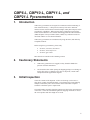
1.
Introduction
CMP-series pyranometers are designed for continuous outdoor monitoring of
solar radiation intensity. A flat spectral sensitivity from 285 to 2800 nm
enables accurate measurements in natural sunlight, under plant canopies, and in
green houses or buildings. When inverted, these pyranometers can measure
reflected solar radiation. Uses include monitoring global horizontal irradiance
(GHI) and plane of array irradiance (POA). Diffuse sky radiation can also be
measured with the use of a shade mechanism.
CMP-series pyranometers are manufactured by Kipp & Zonen, and cabled by
Campbell Scientific.
Before using these pyranometers, please study:
x
x
x
Section 2, Cautionary Statements
Section 3, Initial Inspection
Section 4, Quick Start
More details are available in the remaining sections.
2.
3.
Cautionary Statements
x
CMP-series pyranometers are rugged, but they should be handled as
precision scientific instruments.
x
Care should be taken when opening the shipping package to not damage or
cut the cable jacket. If damage to the cable is suspected, consult with a
Campbell Scientific applications engineer.
Initial Inspection
Check the contents of the shipment. If there is a shortage (see Section 3.1,
Ships With), contact Campbell Scientific. If any damage has occurred during
transport, immediately file a claim with the carrier and contact Campbell
Scientific to facilitate repair or replacement.
The model number and cable length are printed on a label at the connection end
of the cable. Check this information against the shipping documents to ensure
the correct product and cable length are received.
1
CMP6-L, CMP10-L, CMP11-L, and CMP21-L Pyranometers
3.1
Ships With
(2) Bolts for mounting from original manufacturer
(1) Sun Shield from original manufacturer
(2) Nylon washers from original manufacturer
3.2
Calibration Certificate
Each pyranometer is shipped with an instruction manual provided by Kipp &
Zonen that contains information concerning its construction, spectral
sensitivity, cosine response, and a simple sensor check out procedure. Included
with the sensor and manual is a calibration certificate with the sensor
sensitivity value and serial number.
Note
4.
Cross check this serial number against the serial number on your
pyranometer to ensure that the given sensitivity value corresponds
to your sensor.
Quickstart
Note
4.1
Appendix A, CVF3, CVF4 Heater/Ventilator, provides the
installation procedure for both ventilation units.
Siting
The pyranometer is usually installed horizontally for global horizontal
measurements. However, the pyranometer can be installed at any angle for
POA measurements and in the inverted position for reflected measurements. In
all cases it will measure the solar flux incident on the sensor surface.
Site the pyranometer to allow easy access for maintenance while ideally
avoiding any obstructions above the plane of the sensing element. It is
important to mount the pyranometer such that a shadow will not be cast on it at
any time.
If this is not possible, try to choose a site where any obstruction over the
azimuth range between earliest sunrise and latest sunset has an elevation not
exceeding 5q. Diffuse solar radiation is less influenced by obstructions near
the horizon. For instance, an obstruction with an elevation of 5q over the
whole azimuth range of 360q decreases the downward diffuse solar radiation
by only 0.8%.
The sensor should be mounted with the cable pointing towards the nearest
magnetic pole (e.g., in the Northern Hemisphere point the cable toward the
North Pole); see Figures 4-1 to 4-4.
2
CMP6-L, CMP10-L, CMP11-L, and CMP21-L Pyranometers
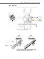
4.2
Mounting
See Section 7.1, Mounting to a Tripod Tower, for more information.
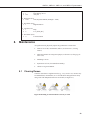
Figure 4-1 Pyranometer installation
CM245 Adjustable
Angle Mounting
Stand
CM2XX-Series
Crossarm
Figure 4-2 Pyranometer mounted horizontally for the Northern
Hemisphere (left) and Southern Hemisphere (right)
3
CMP6-L, CMP10-L, CMP11-L, and CMP21-L Pyranometers
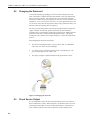
Figure 4-3 Two views of a pyranometer mounted at an angle for the
Northern Hemisphere
Figure 4-4 Pyranometer mounted at an anlge for the Southern
Hemisphere
4
CMP6-L, CMP10-L, CMP11-L, and CMP21-L Pyranometers
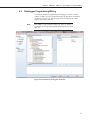
4.3
Datalogger Programming/Wiring
The simplest method for programming the datalogger to measure a CMP6,
CMP10 or CMP11 is to use Campbell Scientific's SCWin Short Cut Program
Generator (see Figure 4.5). Wire the pyranometer according to the wiring
diagram generated by Short Cut.
Note
The CMP21 is not included in Short Cut. Refer to Section 7,
Installation, for wiring and programming information if not using
Short Cut.
Figure 4-5 SCWin Short Cut Program Generator
5
CMP6-L, CMP10-L, CMP11-L, and CMP21-L Pyranometers
5.
Overview
5.1
Models
CMP-series models differ in accuracy and performance. See Section 6,
Specifications. The CMP21 also includes an internal thermistor allowing
individually optimized compensation of the measurements. The –L portion of
the model number indicates that the pyranometer has a user-specified cable
length. The pyranometers have several cable termination options. Their cables
can terminate in:
x
x
x
5.2
Pigtails that connect directly to a Campbell Scientific datalogger
(cable termination option –PT).
Connector that attaches to a prewired enclosure (cable termination
option –PW).
Connector that attaches to a CWS900 Wireless Sensor Interface (cable
termination option –CWS). The CWS900 enables the pyranometer to
be used in a wireless sensor network. Please note that this option is
not available for the CMP21.
Construction
The pyranometers consist of a thermopile sensor, housing, two glass domes,
and cable. The thermopile is coated with a black absorbent coating. The paint
absorbs the radiation and converts it to heat. The resultant temperature
difference is converted to a voltage by the copper-constantan thermopile. The
thermopile is encapsulated in the housing in such a way that it has a field of
view of 180 degrees and the angular characteristics needed to fulfill the cosine
response requirements.
6
CMP6-L, CMP10-L, CMP11-L, and CMP21-L Pyranometers
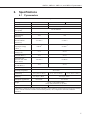
6.
Specifications
6.1
Pyranometers
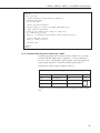
Table 6-1 CMP-Series Specifications
Specification
ISO Classification
Maximum irradiance
Spectral range
(50% points)
Response time (95 %)
Expected daily
uncertainty
Zero offset due to
thermal radiation
(200 W•m–2)
Zero offset due to
temperature change
(5 K•hr–1)
Non-stability
(change/year)
Non-linearity
(0 to 1000 W•m–2)
Directional error
(up to 80° with 1000
W•m–2 beam)
Tilt error
(at 1000 W•m–2)
Level accuracy
Operating temperature
Temperature dependence
of sensitivity
Sensitivity
Typical signal output for
atmospheric applications
Weight
CMP6
First Class
2000 W•m–2
CMP10 and CMP11
CMP21
Secondary Standard
4000 W•m–2
285 to 2800 nm
<18 s
<5 s
<5%
<2%
<15 W•m–2
<7 W•m–2
<4 W•m–2
<2 W•m–2
<1 %
<0.5%
<1%
<0.2%
<20 W•m–2
<10 W•m–2
<1%
<0.2%
0.1°
–40° to 80°C
<4% (–10° to +40°C)
<1% (–10° to +40°C)
<1% (–20° to +50°C)
5 to 20 μV / W•m–2
7 to 14 μV / W•m–2
0 to 20 mV
0 to 15 mV
0.6 kg (1.3 lb) without cable;
0.9 kg (2 lb) with 10 m (33 ft) cable
Impedance*
20 to 200 Ω
10 to 100 Ω
* Impedance is defined as the total electrical impedance at the radiometer output connector fitted to the housing.
It arises from the electrical resistance in the thermal junctions, wires, and passive electronics within the
radiometer.
7
CMP6-L, CMP10-L, CMP11-L, and CMP21-L Pyranometers
Figure 6-1 Dimensions of the CMP6, CMP11, and CMP21
6.2
CVF3 Ventilation Unit
Compatible Pyanometers:
CMP6, CMP10, CMP11, CMP21
Power supply:
12 Vdc, 1.3 A (with 10 W Heater)
Operating temperature range: –40° to 70°C
Ventilation power:
5 W continuously
Heating power:
5 W and 10 W
Heater induced offset:
<1 W•m–2 (with CMP11 Pyranometer)
Weight without cable:
1.6 kg (3.5 lb)
Figure 6-2 Dimensions of the CVF3
6.3
8
CVF4 Ventilation Unit
Compatible Pyanometers:
CMP6, CMP10, CMP11, CMP21
Power supply:
12 Vdc, 0.9 A (with Heater)
CMP6-L, CMP10-L, CMP11-L, and CMP21-L Pyranometers
Operating temperature range: –40° to 70°C
Ventilation power:
5 W continuously
Heating power:
5.5 W
Heater induced offset:
<1 W•m–2 (with CMP10, CMP11
Pyranometer)
Weight without cable:
1.6 kg (3.5 lb)
Figure 6-3 Dimensions of the CVF4
7.
Installation
7.1
Mounting to a Tripod or Tower
Tools required for installation on a tripod or tower:
Small and medium Phillips screwdrivers
5/16”, 1/2” open end wrenches
5/32” Allen wrench
Tape measure
UV-resistant wire ties
Side-cut pliers
Compass
Step ladder
The pyranometers include a bubble level and two leveling screws, which allow
them to be leveled horizontally without using a leveling base. They mount to a
mast, crossarm, or pole (1.0 in. to 2.1 in. outer diameter) via the CM245
Mounting Stand.
9
CMP6-L, CMP10-L, CMP11-L, and CMP21-L Pyranometers
Note
If using a CFV3 or CVF4 Ventilation Unit, a different mounting
stand, the 27084 is required. Refer to Appendix A, CVF3 and
CVF4 Heater/Ventilator, for more information.
The CM245 includes slots that allow it to be adjusted to any angle from
horizontal to vertical. If mounting the pyranometer at an angle, ensure that the
crossarm is leveled horizontally before placing the bracket at its proper angle.
Angle positions are included on the bracket label (see Figures 7-1 and 7-2).
Pyranometer
mounts here
First
2.125”
u-bolt
Second
2.125”
u-bolt
First
2.125”
u-bolt
90
Second
2.125”
u-bolt
Figure 7-1 CM245 bracket with 2.125" u-bolts positioned to mount the
pyranometer horizontally on a crossarm
10
CMP6-L, CMP10-L, CMP11-L, and CMP21-L Pyranometers
First
1.5”
u-bolt
40
Second
1.5”
u-bolt
Figure 7-2 CM245 bracket with 1.5" u-bolts positioned to mount
pyranometer at a 40° angle on a vertical pipe
Do the following to level the pyranometer horizontally (see Error! Reference
ource not found.):
1. Attach the mounting stand to the crossarm.
2. Loosely mount the pyranometer on the mounting stand. Do not fully
tighten the two mounting screws.
3. Turn the leveling screws as required to bring the bubble of the level within
the ring.
4. Tighten the mounting screws to secure the assembly in its final position.
Check that the pyranometer is still correctly leveled and adjust as necessary.
5. Attach the white plastic sun screen to the pyranometer.
11
CMP6-L, CMP10-L, CMP11-L, and CMP21-L Pyranometers
Sun shield
Mounting screws
Nylon washers
Bubble level
Pyranometer
Levelling screw
CM245
mounting stand
Crossarm
6.
Figure 7-3 Exploded view of the pyranometer mounting
7.2
Wiring
Note
Short Cut users should wire the sensor according to the wiring
diagram generated by Short Cut.
The cable of the CMP6, CMP10 and CMP11 has two conductors and a shield.
The cable of the CMP21 has five conductors and a shield. The additional
conductors on the CMP21’s cable are for connecting its internal thermistor. A
schematic for the CMP6, CMP10, CMP11, and the thermopile of the CMP21 is
provided in Section 7.2.1 CMP6, CMP11, and CMP21 Thermopile Schematic.
Wiring for the CMP6, CMP10, and CMP11 is described in Section 7.2.2,
CMP6 and CMP11 Wiring, wiring for the CMP21 is described in Section 7.2.3,
CMP21 Wiring.
12
CMP6-L, CMP10-L, CMP11-L, and CMP21-L Pyranometers
7.2.1 CMP6, CMP10, CMP11, and CMP21 Thermopile Schematic
A schematic diagram of a CMP6, CMP10, CMP11, or CMP21 thermopile is
shown in Figure 7-4.
Red
White (+)
Blue
Black (-)
Black
Shield
Figure 7-4 CMP6, CMP10, CMP11, or CMP21 thermopile detector
schematic
7.2.2 CMP6 and CMP11 Wiring
Note
CMP6, CMP10, or CMP11 purchased from Campbell Scientific
has different wiring than a pyranometer purchased directly from
Kipp & Zonen.
The pyranometer is measured using either differential analog channels or
single-ended analog channels.
A differential voltage measurement is recommended because it has better noise
rejection than a single-ended measurement.
Connections to Campbell Scientific dataloggers for a differential measurement
are given in TABLE 7-1. A user-supplied jumper wire should be connected
between the low side of the differential input and ground (AG or ) to keep
the signal in common mode range.
Connections to Campbell Scientific dataloggers for a single-ended
measurement are given in TABLE 7-2able 7-2.
TABLE 7-1. CMP6, CMP10 and CMP11 Differential Connections to Campbell Scientific Dataloggers
Color
Description
CR9000(X), CR5000,
CR3000, CR1000,
CR800
White
Signal (+)
DIFF Analog High
DIFF Analog High
DIFF Analog High
Black
Signal (–)
*DIFF Analog Low
*DIFF Analog Low
*DIFF Analog Low
Shield
Shield
* Jumper to AG or
CR510, CR500,
CR10(X)
21X, CR7, CR23X
G
with user supplied 26 AWG or larger wire.
13
CMP6-L, CMP10-L, CMP11-L, and CMP21-L Pyranometers
TABLE 7-2. CMP6, CMP10 and CMP11 Single-Ended Connections to Campbell Scientific Dataloggers
Color
Description
CR9000(X), CR5000,
CR3000, CR1000,
CR800
White
Signal (+)
SE Analog
Black
Signal (–)
AG
Clear
Shield
G
CR510, CR500,
CR10(X)
21X, CR7, CR23X
SE Analog
SE Analog
7.2.3 CMP21 Wiring
Note
A CMP21 purchased from Campbell Scientific has different
wiring than a CMP21 purchased directly from Kipp & Zonen.
The CMP21’s pyranometer can be measured using either differential analog
channels or single-ended analog channels. A differential voltage measurement
is recommended because it has better noise rejection than a single-ended
measurement. If a differential channel is not available, a single-ended
measurement can be used.
A single-ended channel and a voltage excitation channel are used to measure
the CMP21’s internal thermistor.
Connections to Campbell Scientific dataloggers for a differential measurement
are given in TABLE 7-3able 7-3. A user-supplied jumper wire should be
connected between the low side of the differential input and ground (AG or )
to keep the signal in common mode range. Connections to Campbell Scientific
dataloggers for a single-ended measurement are given in TABLE 7-4able 7-4.
TABLE 7-3. CMP21 Differential Connections to Campbell Scientific Dataloggers
Wire Color
Wire Label/
Description
CR9000(X),
CR5000, CR3000,
CR1000, CR800
CR510, CR500,
CR10(X)
21X, CR7, CR23X
White
Pyranometer Sig
DIFF Analog High
DIFF Analog High
DIFF Analog High
Blue
Pyranometer Ref
*DIFF Analog Low
*DIFF Analog Low
*DIFF Analog Low
Yellow
Thermistor Volt Excite
VX or EX
E
EX
Black
Thermistor Sig
Single-ended analog
Single-ended analog
Single-ended analog
Brown
Thermistor Ref
AG
Clear
Shield
G
* Jumper to AG or
14
with user-supplied wire.
CMP6-L, CMP10-L, CMP11-L, and CMP21-L Pyranometers
TABLE 7-4. CMP21 Single-Ended Connections to Campbell Scientific Dataloggers
CR9000(X),
CR5000, CR3000,
CR1000, CR800
CR510, CR500,
CR10(X)
21X, CR7, CR23X
Wire Color
Wire Label/
Description
White
Pyranometer Sig
Single-ended analog
Single-ended analog
Single-ended analog
Blue
Pyranometer Ref
Yellow
Thermistor Volt Excite
VX or EX
E
EX
Black
Thermistor Sig
Single-ended analog
Single-ended analog
Single-ended analog
Brown
Thermistor Ref
AG
Clear
Shield
G
7.3
AG
Programming
Note
This section is for users who write their own datalogger programs.
You do not need to read this section if using Short Cut Program
Generator, or connecting the pyranonmeter to a prewired
enclosure or CWS900 Wireless Sensor Interface. Our prewired
enclosures include a datalogger program. Refer to the Wireless
Sensor Manual for programming information if using a CMP6,
CMP10 or CMP11 with a CWS900.
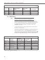
7.3.1 Solar Radiation Measurement
Solar radiation can be reported as an average flux density (W•m–2) or daily
total flux density (MJ•m–2). The appropriate multipliers are listed in TABLE
7-5. Programming examples are given for both average and daily total solar
radiation.
The pyranometers output a low level voltage ranging from 0 to a maximum of
up to 20 mV, in natural light, depending on the calibration factor and radiation
level.
This voltage output is measured using either a differential voltage instruction
(VoltDiff() in CRBasic or Instruction 2 (P2) in Edlog) or a single-ended
voltage instruction (VoltSE() in CRBasic or Instruction 1 (P1) in Edlog).
Caution
Nearby AC power lines, electric pumps, or motors can be a
source of electrical noise. If the sensor or datalogger is
located in an electrically noisy environment, the
measurement should be made with the 60 or 50 Hz rejection
integration option, as shown in the example programs.
7.3.1.1 Input Range
The output voltage is usually between 5 and 20 mV per 1000 W•m–2. When
estimating the maximum likely value of sensor output a maximum value of
solar radiation of 1100 W•m–2 can be used for field measurements on a
horizontal surface. Plane of array irradiances can exceed 1500 W•m–2.
15
CMP6-L, CMP10-L, CMP11-L, and CMP21-L Pyranometers
Select the input range as follows:
1.
Estimate the maximum expected input voltage by multiplying the
maximum expected irradiance (in W•m–2) by the calibration factor (in μV /
W•m–2). Divide the answer by 1000 to give the maximum in millivolt
units.
2.
Select the smallest input range which is greater than the maximum
expected input voltage. Normally the 50 mV range for the CR3000,
CR5000, CR9000(X), CR7, and CR23X and the 25 mV or 250 mV range
for the CR800, CR850, CR1000, CR510, and CR10(X) will be suitable.
The exact range will depend on the sensitivity of your individual sensor
and the maximum expected reading. With some dataloggers an autorange
option can be used if measurement time is not critical.
The parameter code for the input range also specifies the measurement
integration time. The slow or 60 Hz rejection integration gives a more noisefree reading. The 250 μs (CRBasic) or a fast (Edlog) integration takes less
power and allows for faster throughput.
7.3.1.2 Multiplier
The multiplier converts the millivolt reading to engineering units. The
sensitivity value supplied by the manufacturer gives the output of the sensor as
μV (micro-volts) / W•m–2. As the datalogger voltage measurement
instructions give a default output in mV, the following equation should be used
to calculate the multiplier to give the readings in W•m–2:
m = 1000/c
Where,
m = multiplier
c = sensor output in μV / W•m–2
Other units can be used by adjusting the multiplier as shown in TABLE
7-5able 7-5.
TABLE 7-5. Multipliers Required for Flux Density and Total Fluxes
Units
Multiplier
Output Processing
W•m–2
M
Average
MJ•m–2
M * t * 0.000001
Totalize
kJ•m–2
M * t * 0.001
Totalize
cal•cm–2
M * t * 0.0239 * 0.001
Totalize
M * 1.434 * 0.001
Average
t / 3600
Totalize
cal • cm–2 • min–1
–2
W • hr • m
W•m–2
M = calibration factor with units of
/ mV
t = datalogger program execution interval in seconds
16
CMP6-L, CMP10-L, CMP11-L, and CMP21-L Pyranometers
7.3.1.3 Offset
The offset will normally be fixed at zero as the sensor should output no
significant signal in dark conditions. In practice, because of the nature of
thermopile detector sensors, there will be some offset in dark conditions;
sometimes this offset can give negative light readings. This offset varies with
several factors (e.g., rate of change of sensor temperature), so it cannot be
removed with a fixed offset. Some users may wish to remove small negative
readings by including code after the measurement instructions that sets
negative readings to zero.
7.3.1.4 Output Format Considerations
Over-ranging may be an issue if the measurement values are totalized. Overranging can be prevented when using CRBasic by storing the data in the IEEE4
format.
When using Edlog, the largest number the datalogger can store in final storage
is 6999 in low resolution mode (FP2) and 99999 in high resolution mode (if
available). The following example shows how over-ranging can be a problem
for Edlog dataloggers.
Example
Assume that daily total flux is desired, and that the Edlog datalogger scan rate
is 1 second. With a multiplier that converts the readings to units of kJ•m–2 and
an average irradiance of 0.5 kW•m–2, the maximum low resolution output limit
will be exceeded in less than four hours.
Solution 1 – Change the multiplier in the instruction to (m * 0.001). This will
totalize MJ•m–2 instead of kJ•m–2.
Solution 2 – Record the average flux density and later multiply the result by the
number of seconds in the output interval to arrive at total flux.
Solution 3 – Record the total flux using the high resolution format. The draw
back to high resolution is that it requires four bytes of memory per data point,
consuming twice as much memory as low resolution. Instruction 78 is used to
switch to high resolution in the Edlog dataloggers.
7.3.2 CMP21 Internal Thermistor Measurement
The thermistor is measured using a half bridge measurement instruction
(BrHalf instruction in CRBasic or Instruction 5 (P5) in Edlog). The value
provided by the half bridge instruction needs to be converted to resistance and
then converted to temperature.
The following equation is used to convert to resistance:
§ V ·
Res. 1000¨¨ x ¸¸
© 1 Vx ¹
Where,
Vx = the value provided by the half bridge instruction
17
CMP6-L, CMP10-L, CMP11-L, and CMP21-L Pyranometers
In CRBasic, the conversion to resistance is entered as a mathematical
expression. In Edlog, Instruction P59 (Bridge Transform) does the conversion.
The Steinhart-Hart equation is used to convert resistance to temperature. The
Steinhart-Hart equation for converting resistance to degree Celsius is as
follows:
Temperature = 1/[A + B*LN(resistance) + C*(LN(resistance))^3] - 273.15
Where A, B, and C are coefficients for the Steinhart-Hart equation.
The coefficients for the Steinhart-Hart equation are specific to the thermistor
contained in your CMP21. A calibration certificate that lists these coefficients
is shipped with each CMP21 pyranometer.
In CRBasic, the Steinhart-Hart equation is entered as a mathematical
expression. Edlog dataloggers can use Instruction P200 (requires a newer
datalogger operating system).
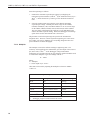
7.3.3 Example Programs
7.3.3.1 CR1000 Example Program for Measuring a CMP6
Although this example is for the CR1000, other CRBasic dataloggers are
programmed similarly. The following program measures the CMP6 every
second and converts the millivolt output to W•m–2. A sensor calibration of
14.33 μV / W•m–2 is used for the example program. Every 10 minutes, the
program outputs the average and standard deviation of the flux (W•m–2)
measurements. Wiring for this example is given in TABLE 7-6able 7-6.
TABLE 7-6. CR1000 Wiring for CMP6 Example Program
Wire Color
Description
CR1000
White
Solar Signal (+)
1H
Black
Solar Signal (–)
1L
Clear
Shield
* Jumper 1L to
'CR1000 Series Datalogger
Public PTemp
Public Batt_Volt
Public CMP6_Irr
Units CMP6_Irr = W/m2
DataTable (TenMin,1,-1)
DataInterval (0,1,Min,4)
Minimum (1,Batt_Volt,FP2,0,False)
Sample (1,PTemp,FP2)
Average (1,CMP6_Irr,FP2,False)
StdDev (1,CMP6_Irr,FP2,False)
EndTable
BeginProg
Scan (1,Sec,0,0)
18
with user-supplied 26 AWG or larger wire.
Jumper*
CMP6-L, CMP10-L, CMP11-L, and CMP21-L Pyranometers
'Measure the Battery Voltage and Panel Temperature
PanelTemp (PTemp,250)
Battery (Batt_Volt)
'Measure the CMP6
VoltDiff (CMP6_Irr,1,mV25C,1,True ,10000,_60Hz,1000/14.33,0)
CallTable TenMin
NextScan
EndProg
7.3.3.2 CR1000 Example Program for Measuring a CMP11
Although this example is for the CR1000, other CRBasic dataloggers are
programmed similarly. The following program measures the CMP11 every
second and converts the millivolt output to W•m–2. A sensor calibration of
8.55 μV / W•m–2 is used for the example program. Every 10 minutes, the
program outputs the average and standard deviation of the flux (W•m–2)
measurements.
Wiring for this example is given in TABLE 7-7able 7-7.
TABLE 7-7. CR1000 Wiring for CMP11 Example Program
Wire Color
Description
CR1000
White
Solar Signal (+)
2H
Black
Solar Signal (–)
2L
Clear
Shield
* Jumper 2L to
Jumper*
with user-supplied 26 AWG or larger wire.
'CR1000 Series Datalogger
Public PTemp
Public Batt_Volt
Public CMP11_Irr
Units CMP11_Irr = W/m2
DataTable (TenMin,1,-1)
DataInterval (0,1,Min,4)
Minimum (1,Batt_Volt,FP2,0,False)
Sample (1,PTemp,FP2)
Average (1,CMP11_Irr,FP2,False)
StdDev (1,CMP11_Irr,FP2,False)
EndTable
BeginProg
Scan (1,Sec,0,0)
'Measure the Battery Voltage and Panel Temperature
PanelTemp (PTemp,250)
19
CMP6-L, CMP10-L, CMP11-L, and CMP21-L Pyranometers
Battery (Batt_Volt)
'Measure the CMP11
VoltDiff (CMP11_Irr,1,mV25C,2,True ,10000,_60Hz,1000/8.55,0)
CallTable TenMin
NextScan
EndProg
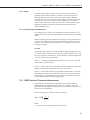
7.3.3.3 CR1000 Example Program for Measuring a CMP21
Although this example is for the CR1000, other CRBasic dataloggers are
programmed similarly. The following program measures the CMP21 every
second. It converts the pyranometer’s millivolt output to W•m–2. A
pyranometer calibration of 8.65 μV / W•m–2 is used for the example program.
The resistance of the internal thermistor is converted to degree Celsius and then
to Kelvin. Every 10 minutes, the program outputs the average and standard
deviation of the flux (W•m–2) measurements and temperature measurements.
Wiring for this example is given in TABLE 7-8able 7-8.
TABLE 7-8. CR1000 Wiring for CMP21 Example Program
Wire Color
White
Blue
Description
Solar Signal (+)
Solar Signal (–)
CR1000
3H
3L
Yellow
Black
Brown
Clear
Voltage Excitation
Temp Signal
Signal Reference
Shield
VX1
15 SE
* Jumper 3L to
'CR1000 Series Datalogger
Public PTemp
Public Batt_Volt
Public CMP21_Irr
Public CMP21_T_C
Public CMP21_T_K
Dim Rs,Vs_Vx
Units CMP21_Irr = W/m2
Units CMP21_T_C = Degrees C
Units CMP21_T_K = Degrees K
DataTable (TenMin,1,-1)
DataInterval (0,1,Min,8)
Minimum (1,Batt_Volt,FP2,0,False)
Sample (1,PTemp,FP2)
Average (1,CMP21_Irr,FP2,False)
StdDev (1,CMP21_Irr,FP2,False)
Average (1,CMP21_T_C,FP2,False)
StdDev (1,CMP21_T_C,FP2,False)
Average (1,CMP21_T_K,FP2,False)
StdDev (1,CMP21_T_K,FP2,False)
EndTable
20
with user-supplied 26 AWG or larger wire.
Jumper*
CMP6-L, CMP10-L, CMP11-L, and CMP21-L Pyranometers
BeginProg
Scan (1,Sec,0,0)
‘Measure the Battery Voltage and Panel Temperature
PanelTemp (PTemp,250)
Battery (Batt_Volt)
‘Measure the CMP21 pyranometer
VoltDiff (CMP21_Irr,1,mV25C,3,True,10000,_60Hz,1000/8.65,0)
'CMP21 Thermistor Measurement
BrHalf (Vs_Vx,1,mV5000,15,Vx1,1,2500,True ,0,250,1.0,0)
Rs = 1000*(Vs_Vx/(1-Vs_Vx))
CMP21_T_C = 1/(1.0295e-3+2.391e-4*LN(Rs)+1.568e-7*(LN(Rs))^3)-273.15
'Convert CMP21 temp to Kelvin.
CMP21_T_K = CMP21_T_C+273.15
CallTable TenMin
NextScan
EndProg
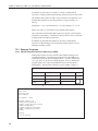
7.3.3.4 CR10X Example Program for Measuring a CMP6
The following program uses a CR10X to measure a CMP6 every 10 seconds
and convert the mV output to W•m–2 and MJ•m–2. A sensor calibration of
14.33 μV / W•m–2 is used for this example program. The program outputs an
hourly average flux (W•m–2), and a daily total flux density (MJ•m–2).
Wiring for the example is given in TABLE 7-9able 7-9.
TABLE 7-9. CR10X Wiring for CMP6 Example Program
Wire Color
Description
CR10X
White
Solar Signal (+)
1H
Black
Solar Signal (–)
1L
Clear
Shield
AG
Jumper*
* Jumper 1L to AG terminal on CR10X with user-supplied 26 AWG or larger
wire.
21
CMP6-L, CMP10-L, CMP11-L, and CMP21-L Pyranometers
;{CR10X}
*Table 1 Program
01: 10.0000
Execution Interval (seconds)
; CMP6 measurement in W/m2
1: Volt (Diff) (P2)
1: 1
2: 23
3: 1
4: 3
5: 69.7837
6: 0
Reps
25 mV 60 Hz Rejection Range
DIFF Channel
Loc [ Solar_Wm2 ]
Multiplier
Offset
;use the 50 mV range for the CR7, 21X and CR23X
;use the 250 mV range for the CR10X if
;calibration factor is > 25 μV/Wm-2
;1000/14.33
; Set negative values to zero
2: If (X<=>F) (P89)
1: 3
X Loc [ Solar_Wm2 ]
2: 4
<
3: 0
F
4: 30
Then Do
3: Z=F x 10^n (P30)
1: 0
F
2: 0
n, Exponent of 10
3: 3
Z Loc [ Solar_Wm2 ]
4: End (P95)
; Calculate units in MJ, where MJ = m * t * 0.000001.
; m = Solar_Wm2 from above, and t = 10 (scan interval).
5: Z=X*F (P37)
1: 3
2: .00001
3: 4
X Loc [ Solar_Wm2 ]
F
Z Loc [ Solar_MJ ]
6: If time is (P92)
1: 0
Minutes (Seconds --) into a
2: 60
Interval (same units as above)
3: 10
Set Output Flag High (Flag 0)
7: Set Active Storage Area (P80)
1: 1
Final Storage Area 1
2: 101
Array ID
8: Real Time (P77)
1: 1220
Year,Day,Hour/Minute (midnight = 2400)
9: Average (P71)
1: 1
Reps
2: 3
Loc [ Solar_Wm2 ]
10: If time is (P92)
1: 0
Minutes (Seconds --) into a
2: 1440
Interval (same units as above)
3: 10
Set Output Flag High (Flag 0)
22
CMP6-L, CMP10-L, CMP11-L, and CMP21-L Pyranometers
11: Set Active Storage Area (P80)
1: 1
Final Storage Area 1
2: 102
Array ID
12: Real Time (P77)
1: 1220
Year,Day,Hour/Minute (midnight = 2400)
13: Resolution (P78)
1: 1
High Resolution
14: Totalize (P72)
1: 1
Reps
2: 4
Loc [ Solar_MJ ]
15: Resolution (P78)
1: 0
Low Resolution
8.
Maintenance
At regular intervals, physically inspect the pyranometer to ensure that:
8.1
x
Dome is free of dirt, condensation, and ice (see Section 8.1, Cleaning
Domes).
x
Desiccant granules are orange and opaque (see Section 8.2, Changing the
Desiccant).
x
Mounting is secure.
x
Pyranometer is level (if mounted horizontally).
x
Cables are in good condition.
Cleaning Domes
Clean the outer dome at regular intervals (e.g., every week or so). Remove any
accumulated dust, condensation, or ice from the dome and pyranometer body
using a soft cloth dampened with water or alcohol (see Figure 8.1).
Figure 8-1 Reading is reduced if dome is not dry or clean
23
CMP6-L, CMP10-L, CMP11-L, and CMP21-L Pyranometers
8.2
Changing the Desiccant
A desiccant-filled drying cartridge prevents dew from forming on the inner
sides of the domes; Campbell Scientific part number 27052 is the replacement
desiccant for this cartridge. The optional CVF3 or CVF4 Heater/Ventilator
Unit is also available to keep the pyranometer dome free from ice and dew (see
Appendix A, CVF3, CVF4 Heater/Ventilator). In some applications, the CVF3
or CVF4 may also reduce the deposition of dust on the pyranometer dome, and
therefore reduce the cleaning interval frequency.
The silica gel desiccant granules in the drying cartridge should be orange and
opaque. Replace the desiccant granules when they become translucent
(normally after several months). Refill packs of desiccant are shipped with the
pyranometer and can be purchased from Campbell Scientific. The drying
cartridge uses the content of one refill pack. Figure 8-2 shows the replacement
process.
When changing the desiccant, ensure that:
x
The surfaces touching the rubber o-ring are clean. Dirt, in combination
with water, can cause corrosion, harming it.
x
7KH rubber o-ring is coated with silicon grease or petroleum jelly. The
grease coating improves the o-ring’s seal.
x
The drying cartridge is tightly threaded into the pyranometer’s body.
Figure 8-2 Changing the desiccant
8.3
Check Sensor Output
It is also important to check the data returned from the sensor as it will show
the first indication of a fault. When doing this you should be aware of several
expected phenomena that can cause strange measurements. In particular on
clear, windless nights the outer dome temperature of horizontally placed
24
CMP6-L, CMP10-L, CMP11-L, and CMP21-L Pyranometers
pyranometers can fall as low as the dew point temperature of the air, due to
infrared radiation exchange with the cold sky. The effective sky temperature
can be 30°C lower than the ground temperature, which results in an infra-red
emission of –150 W•m–2. If this happens, dew, glazed frost or hoar frost can be
precipitated on the top of the outer dome and can stay there for several hours in
the morning. An ice cap on the dome is a strong diffuser and can increase the
pyranometer signal by up to 50% in the first hours after sunrise.
8.4
Recalibration
The calibration of the pyranometer may drift with time and exposure to
radiation. Recalibration every two years is recommended. The sensor should
be returned to Campbell Scientific for recalibration. A Returned Materials
Authorization (RMA) is required (refer to the Assistance page for more
information).
9.
Troubleshooting
Symptom: NAN, –9999, or radiation values around 0
1.
Check that the sensor is wired to the differential channel specified by the
measurement instruction.
2.
Verify that the range code is correct for the datalogger type.
3.
Measure the impedance across the red and blue sensor wires. This should
be around 100 ohms plus the cable resistance (typically 0.1 ohm•m–1). If
the resistance is very low, there may be a short circuit (check the wiring).
Resistances somewhat lower than expected could be due to water ingress
into the sensor or enclosure connectors. If the resistance is infinite, there
is a broken connection (check the wiring).
4.
Disconnect the sensor cable and check the voltage output from the sensor.
With the sensor located 8” below a 60 W incandescent light bulb the
voltage should be approximately 2.5 mV. No voltage indicates a problem
with the sensor.
Symptom: sensor signal is unrealistically high or low
1.
Check that the right calibration factor has been properly entered into the
datalogger program. Please note that each sensor has its own individual
calibration factor.
2.
Check the condition of the sensor cable.
Symptom: sensor signal shows unexpected variations
1.
Check for the presence of strong sources of electromagnetic radiation
(radar, radio, etc.).
2.
Check the condition and the connection of the sensor shield wire.
3.
Check the condition of the sensor cable.
25
CMP6-L, CMP10-L, CMP11-L, and CMP21-L Pyranometers
26
Appendix A. CVF3, CVF4 Heater
Ventilator
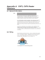
A.1 General Information
Note
The CVF3 has been discontinued and replaced by the CVF4.
The CVF3 and CVF4 consist of a ventilation unit and heaters. The 5 W
ventilation unit uses a fan and inlet filter to draw clean air over the
pyranometer’s domes. The fan runs continuously to reduce dust and dirt
settling, to dissipate rain drops, and to stabilize the dome temperature.
The CVF3 has both a 5 W and a 10 W heater. The CVF4 has a 5.5 W heater.
The CVF3 5W heater raises the temperature of the dome slightly above
ambient temperature to prevent the formation of dew and frost. The CVF3 10
W heater is used to melt snow and ice. With improvements in design and
efficiency all of these preventative measures are performed by the CVF4 5.5 W
heater.
These power requirements are large compared to most Campbell Scientific
products. Because of this, the CVF3 and CVF4 require additional
consideration for power supplies and control. Please review these matters with
a Campbell Scienttific (Canada) Measurement Consultant so any concerns can
be addressed.
A.2 Siting
Siting information provided in Section 4.1, Siting, is pertinent when using the
CVF3 or CVF4 heater/ventilation. Additionally, the area directly under the
CVF3 or CVF4’s intake needs to be free from snow, leaves, or other
obstructions that could inhibit the air flow (see Figure A-1).
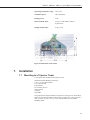
A-1 Transparent view of CVF3 showing air flow
A-1
CVF3, CVF4 Heater Ventilator
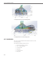
A-2 Transparent front view of CVF4 showing air flow
A-3 Tranparent side view of CVF4 showing air flow
A.3 Installation
The CVF3 or CVF4 unit includes the heater/ventilator unit, white cover, cable,
and mounting hardware.
Tools required for mounting to a tripod or tower are:
A-2
x
Small and medium Phillips screwdrivers
x
5/16”, 1/2” open end wrenches
x
5/32” Allen wrench
x
Tape measure
x
UV-resistant wire ties
x
Side-cut pliers
CMP6-L, CMP10-L, CMP11-L, and CMP21-L Pyranometers
x
Compass
x
Step ladder
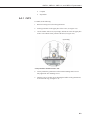
A.3.1 CVF3
To install, do the following:
1.
Remove leveling screws from the pyranometer.
2.
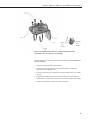
Fit the pyranometer in the upper plate of the CVF3 (see Figure A-4).
3.
Use the counter sink screws, nylon rings, and nuts to secure the upper plate
of the CVF3 with the lower portion of the unit (see Figure A-4).
Nylon Ring
A-4 Pyranometer mounted to the CVF3
4.
Loosely mount the pyranometer on the 27084 mounting stand. Do not
fully tighten the two mounting screws.
5.
Turn the CVF3’s leveling screws bringing the bubble of the pyranometer’s
level within the ring (see Figure A-6).
A-3
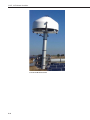
CVF3, CVF4 Heater Ventilator
A-5 CVF3 installed onsite
6.
Tighten the mounting screws to secure the assembly in its final position.
Check that the pyranometer is still correctly leveled and adjust as
necessary.
7.
Use the cover’s screws to fasten the white cover to the pyranometer (see
Figure A-6).
A-6 Fastening cover on CVF3
A-4
CMP6-L, CMP10-L, CMP11-L, and CMP21-L Pyranometers
8.
Attach the power cable to the CVF3 connector.
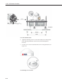
A.3.2 CVF4 Installation
To install, do the following:
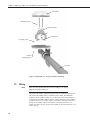
1. Screw the CVF4 flat onto the mounting plate. Be sure to position the CVF4
so that the fan sticks out over the edge of the plate. See Figure A-7 for the
CVF4 mounting holes size and distances. The CVF4 is mounted with the
supplied washers and screws to the L31153 mount. Please note that 4 sets of
mounting hardware are included to mount the CVF4.
Ø 7 mm (2x)
A-7 Mounted CVF4
2. Mount the radiometer in the CVF4 and level with its own levelling feet. The
radiometer mounting screws and shoulder washers are fitted (not secured).
Note
If the CVF4 is mounted on a solar tracker, finish the alignment of
the traker first before securing the radiometer screws.
3. After all mounting screws have been secured, the CVF4 and radiometer
cables can be connected. The radiometer cable goes (down) through the slit in
the CVF4 base plate.
4. Put the CVF4 cover on; the 2 cover nuts can be fastened. Make sure the
cover is horizontal (check that there is equal space around the radiometer
dome) and that the 2 cover nuts are fastened hand tight.
A-5
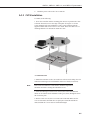
CVF3, CVF4 Heater Ventilator
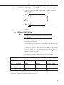
A-8 L31153 Mounted CVF4
A-6
CMP6-L, CMP10-L, CMP11-L, and CMP21-L Pyranometers
A.4 Wiring
Wiring of the CVF3 is shown in Table A-1. Refer to Section 7.2, Wiring, for
information about wiring the pyranometer.
Table A-1 CVF3 Wiring
TABLE A-2 CVF3 Wiring
Wire Color
Description
Connection
Red
Ventilator Power
+12V on Power Supply
Brown
Ventilator Power
+12V on Power Supply
Blue
Heater/Ventilator Ground
G on Power Supply
Black
Heater/Ventilator Ground
G on Power Supply
Gray
Heater/Ventilator Ground
G on Power Supply
Green
5 W Heater Power
+12V on Power Supply
White
5 W Heater Power
+12V on Power Supply
Clear
Shield
Yellow
5 V Tacho Output
on Power Supply
Control port on datalogger
TABLE A-2. CVF4 Wiring
Wire Color
Description
Connection
Red
Ventilator Power
+12V @ 0.4A
Blue
5 W Heater Power
+12V @ 0.5A
Green
Heater/Ventilator Ground
G on Power Supply
Clear
Shield
Yellow
5 V Tacho Output
on Power Supply
Control port on datalogger
A.5 Maintenance
A.5.1 CVF3
1.
Refer to Section 8, Maintenance, for the pyranometer’s maintenance.
2.
Inspect the area directly under the 120 mm diameter hole in the mounting
plate to ensure that it is free from leaves, snow, or other obstructions that
can inhibit air flow.
3.
Unclip the CVF3’s filter cover and check the filters (see Figure A-9).
4.
Replace filters as needed.
A-7
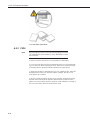
CVF3, CVF4 Heater Ventilator
A-9 CVF3 filter replacement
A.5.2 CVF4
Note
Regular inspection of the CVF4 is advised. Depending on location
(air pollution) this can be monthly or yearly. Remember to check
the CVF4 filter.
1. Refer to Section 8, Maintenance, for pyranometer’s maintenance.
2. For access to the desiccant, the 2 mounting nuts have to be loosened and the
top cover taken off. When replacing the cover, make sure it is placed correctly
by checking that the opening around the radiometer is evenly spaced.
3. Inspect the fan inlet by unclipping the cover. For optimal air flow, make sure
the diagonal line on the cover is in line with the ventilator. The filter cover
clicks back on the ventilator.
4. Be sure to clean and replace the filter every 6 months. The interval strongly
depends on the location and air pollution. Discoloration or pollution of the
plastic cover will not affect the proper operation of the radiometer. Cleaning of
the cover can be done with water and a brush or cloth.
A-8
A-1