1
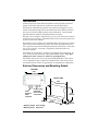
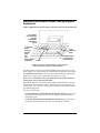
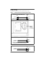
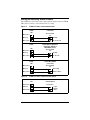
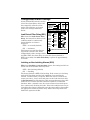
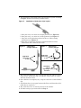
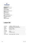
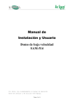
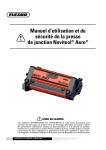
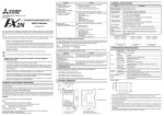
Infrastructure Management & Monitoring
For Business-Critical Continuity™
Liebert Liqui-tect® 460
Installation Manual - Zone Leak Detection Sensor
TABLE OF CONTENTS
INTRODUCTION . . . . . . . . . . . . . . . . . . . . . . . . . . . . . . . . . . . . 1
EXTERIOR DIMENSIONS AND MOUNTING DETAILS. . . . . . . . . . . 1
PLACEMENT ON SUBFLOOR UNDER COOLING SUPPORT
EQUIPMENT . . . . . . . . . . . . . . . . . . . . . . . . . . . . . . . . . . . . . . 2
POWER WIRING . . . . . . . . . . . . . . . . . . . . . . . . . . . . . . . . . . . 3
WIRING TO AUXILIARY ALARM PANELS . . . . . . . . . . . . . . . . . . 4
CONFIGURATION SWITCH SETTINGS . . . . . . . . . . . . . . . . . . . . 5
Leak Detect Filter Delay(SS1) . . . . . . . . . . . . . . . . . . . . . . . . . . 5
Latching or Non-Latching Alarms (SS2) . . . . . . . . . . . . . . . . . . 5
Alarm Retest Delay (SS3) . . . . . . . . . . . . . . . . . . . . . . . . . . . . . . 6
LED OPERATION . . . . . . . . . . . . . . . . . . . . . . . . . . . . . . . . . . 7
NOTES . . . . . . . . . . . . . . . . . . . . . . . . . . . . . . . . . . . . . . . . . . 7
INSTALLATION OF LEAK DETECTION SYSTEM CABLE . . . . . . . . 8
LEAK DETECTION KIT INSTALLATION SCENARIOS . . . . . . . . . 10
i
ii
Introduction
Liebert Liqui-tect® Leak Detection Sensors install quickly and work
simply for reliable detection of conductive aqueous fluid leaks.
The Liqui-tect 460 Sensor provides zone protection using the easy-toinstall and quick-drying Liebert leak detection cable. LEDs located on
the top cover of the module provide visual indication. A reset button
provides optional manual acknowledgement of alarms.
The top cover is hinged, allowing easy access to the electronics housed
inside the steel enclosure. Terminal blocks allow easy interconnection
of power and alarm outputs.
Dual Form-C relay outputs can simultaneously signal the local alarm
panel and remote monitoring system. The Liqui-tect 460 Sensor features supervised operation through alarms for cable faults, circuit failure or loss of power, ensuring a completely self-monitored leak
detection system.
The LT460 is conveniently available in packaged kits with 20, 25, 30,
35 or 45 feet of leak detection cable and hold-down clips. Note that
additional cable cannot be added to packaged kits.
The LT460 sensor can also be purchased independently. The sensor
can accommodate up to 100 feet of leak detection cable if the sensor
and leak detection cables are purchased as independent components.
Exterior Dimensions and Mounting Details
TOP VIEW
4.75"
(120.65mm)
FRONT VIEW
4.25"
(108mm)
Leak
detection
cable
connector
Form-C relay
outputs &
power wiring
connection
3.25"
(83mm)
4.75"
(121mm)
Shipping weight: 2 Ibs (0.9 kg)
Mounting holes: #8 screws
1
2"
(51mm)
Placement on Subfloor Under Cooling Support
Equipment
(Other applications such as long perimeter walls can be monitored)
To a Liebert
environmental
unit and
an optional*
monitoring
panel
To external
power
supply or
directly
from
unit
(see
Power Wiring
on page 3)
Leak
detection
cable
Leak detection
zone (directly
beneath unit)
LT460
* Output connections to external alarm monitoring panels
such as the Liebert contact closure alarm panels
As shown above, the Liqui-tect 460 (LT460) may be placed on a subfloor, where it is connected to the leak detection cable that surrounds
the leak detection zone—the area directly beneath the unit being
protected or other areas such as the perimeter of a room.
Note: For a downflow unit, the leak detection cable must be
located six feet in front of the unit.
The LT460 requires a 24 VAC power supply either from the environmental unit or an external source. There are two sets of Form-C dry
contacts for connection to a Liebert environmental unit and an external monitoring panel.
For more information:
• See Installation of Leak Detection System Cable on page 8 for
instructions on installing the cable and proper placement of the
hold-down clips.
• See Leak Detection Kit Installation Scenarios on page 10 for
cable placement, distance from the unit, and part numbers.
2
Power Wiring
The LT460 is rated for 24 VAC, 50/60 Hz and 0.12 amp.
Figure 1
24V from Liebert environmental units to LT460
Challenger, Himod or
Liebert
Deluxe System/3,
MM2DS,
(8 Ton)
LT460
Challenger, Himod or Mini-Mate2 (8 ton)
LT460
TB1
TB1
TB1
TB1
T5 (24V)
T5 (24V)
TB1-1
TB1-1
G5 (Ground)
(Ground)
G5
TB1-2
TB1-2
Liebert MM2 (1 to 5 Ton)
LT460
TB1
Power Wiring
4V transformer of
(24V)
here are no
ated terminal
24V(Ground)
from Liebert
tions)
TB1-1
Environmental Unit to LT460
Liebert Deluxe Sys/3,
24V fromHimod
Transformer
Challenger,
or
MM2 (8 Ton)
T5 (24V)
connection
on Liebert unit
to LT460
LT460
LT460
Transformer
TB1
TB1
TB1
T5 (24V)
G5
TB1-2
Location of
From 24V
transformer
(Ground)
MM2 (1 to(15 to
Ton)
LiebertLiebert
Mini-Mate2
5 ton)
TB1-1
TB1-1
TB1-2
TB1-2
LT460
LT460
TB1
TB1
4V transformer of
(24V)
here are no
From
24V
ated terminal
transformer*
(Ground)
tions)
TB1-1
TB1-1
TB1-2
TB1-2
* Requires a 24V external transformer (there are
no designated terminal connections on the unit)
Figure 2
24V from Transformer to LT460
24V from transformer to LT460
Transformer
Transformer
LT460
LT460
TB1
TB1
TB1-1
TB1-1
From
24V24V
From
transformer
transformer
TB1-2
TB1-2
3
Wiring to Auxiliary Alarm Panels
The LT460 has two Form-C dry contact alarm output contacts (TB2 &
TB3). Each contact is rated for 24 VAC at 3 amp.
Figure 3
LT460 to Liebert environmental units
Liebert Deluxe Sys/3,
Challenger, Himod or
MM2Liebert
(8 Ton) DS
LT460
LT460
TB2
Environmental
Env.unit
Unit
TB2-3 (N.C.)
(N.C.)
TB2-3
TB2-2 (C)
(C)
TB2-2
(24V)
24 (24V)
TB2-1 (N.O.)
(N.O.)
TB2-1
50, 51, 55 or 56
51
LT460
Liebert Deluxe System/3,
Liebert MM2 (1
to 5 Ton)or
Challenger,
Himod
Mini-Mate2 (8 ton)
LT460
TB2
Environmental
Env.unit
Unit
TB2-3 (N.C.)
(N.C.)
TB2-3
TB2-2 (C)
(C)
TB2-2
24 (24V)
TB1-1
(24V)
TB2-1
TB2-1 (N.O.)
(N.O.)
TB1-2
51, 55 or 56
LT460
LT460
TB2
TB2
OR
Liebert MM2
(1 to 5 Ton)
Liebert
Mini-Mate2
(1 to 5 ton)
Environmental
Env.unit
Unit
TB2-3 (N.C.)
(N.C.)
TB2-3
TB2-2 (C)
(C)
TB2-2
TB1-1 (24V)
(24V)
TB2-1 (N.O.)
(N.O.)
TB2-1
TB1-2 or TB1-3
TB1-3
Figure 4
LT460 to Liebert contact monitor panel
LT460
LT460
Liebert Contact
Liebert
contact
Monitor Panel
monitor
panel
TB2
TB2-3(N.C.)
(N.C.)
TB2-3
Alarm panel
Panel
Input
contact
Contact
(N.O.)
(N.O.)
TB2-2(C)
(C)
TB2-2
TB2-1(N.O.)
(N.O.)
TB2-1
4
Configuration Switch Settings
A four-position DIP switch is used to
select two alarm (filter) delays and
three mutually exclusive alarm
modes. The switches are located
next to the wiring termination
blocks.
1.
2.
3.
4.
Leak Detect Filter Delay(SS1)
Contacts
Rating:
Switch Settings
Leak Detect Filter
Alarm Latch
Alarm Retest Delay
Not Used
S1
OFF ON
10sec 2min
No
Yes
No
1hr
—
—
ALL CIRCUITS: CLASS 2
Contacts shown in POWERED, NON-ALARM state
24V,3A
TB3-3
TB3-2
TB3-1
N.C.
C
2
N.O.
SS1 selects the leak detect filter
N.C.
TB2-3
delay, the interval for which a leak
Contacts
C
Rating:
TB2-2
condition must be continuously
1
24V,3A
TB2-1
N.O.
detected before an alarm is
24V
triggered:
TB1-2
50/60Hz
TB1-1
OFF = 10 seconds (default)
0.12A
ON = 2 minutes
CONNECT ENCLOSURE TO EARTH GROUND
This feature is useful for eliminating nuisance alarms. SS1 works
independently of the settings of SS2
and SS3. While the alarm delay is selectable (factory default is
OFF=10 seconds), the cable fault delay is preset at approximately
2 seconds.
Latching or Non-Latching Alarms (SS2)
SS2 selects latching or non-latching alarms, the setting in which an
alarm will latch ON until manually reset:
OFF = Non-latching (default)
ON = Latching
The factory default is OFF=Non-latching. If the sensor is in latching
mode (ON=Latching) and the leak condition clears itself in the
interim, a manual reset is required. While the alarm is latched, the
sensor goes into a “sleep” mode and power to the leak detection cable
is discontinued. De-powering the cable prevents damage to the cable
should it be in contact with the conductive liquid for an extended
duration. After a manual reset, the sensor resumes its normal operation, continuously checking for leaks. If the leak condition has not yet
cleared but the sensor is manually reset, the sensor will re-alarm after
the appropriate leak detect filter delay. SS2 in the ON position will
disable the operation of SS3.
5
Alarm Retest Delay (SS3)
SS3 selects the alarm retest delay, the setting in which an alarm is
latched and retested every hour.
OFF = Non-latching (default)
ON = Latching-retest each hour
The factory default is OFF=Non-latching. If SS3=ON and a leak is
detected, the alarm condition is latched, the sensor goes into a “sleep”
mode and power to the leak detection cable is discontinued. After one
hour, the sensor will automatically retest if the leak is still present. If
the leak has cleared itself, the sensor deactivates the alarm, resets
itself and resumes normal operation; if the leak is still present, the
alarm condition remains activated and the sensor goes to “sleep” and
retests in another hour. This procedure will repeat indefinitely until
the leak is cleared or until the alarm is manually reset.
A manual reset can be initiated at any time. If the leak condition has
not yet cleared, the sensor re-alarms after the selected leak detect filter delay; if the leak has cleared, the sensor deactivates the alarm and
resets itself. SS3 is disabled if SS2=ON.
The factory default settings of SS2=OFF and SS3=OFF place the
sensor in a non-latching, continuous retest mode. The sensor does not
go to “sleep” after detecting a leak—instead, it continually checks to
determine whether the leak condition has cleared itself. Alarms automatically reset when the leak condition clears. Initiating a manual
reset will cause the sensor to trigger the alarm again after the selected
leak detect filter delay. The leak detect cable remains powered at all
times.
SS4 is not used.
SS1
SS2
SS3
SS4
MODE
OFF
OFF
OFF
(not
used)
Non-latching, 10-second filter delay
(factory default)
ON
OFF
OFF
(not
used)
Non-latching, 2-minute filter delay
OFF
ON
—
(not
used)
Latching, 10-second filter delay
ON
ON
—
(not
used)
Latching, 2-minute filter delay
OFF
OFF
ON
(not
used)
1-hour latch/retest, 10-second filter delay
ON
OFF
ON
(not
used)
1-hour latch/retest, 2-minute filter delay
6
LED Operation
Liqui-tect® Sensor
LT460
System
Normal
Alarm
Pending
Leak
Detected
Reset
Cable
Fault
System Normal (Green):
• ON continuously when power is applied
to sensor.
Alarm Pending (Yellow):
• ON continuously during leak detect filter
delay and cable fault delay.
• FLASHING (with Leak Detected LED) to
indicate cable fault condition.
Leak Detected (Red):
• FLASHING to indicate leak detected
alarm.
• FLASHING (with Alarm Pending LED)
to indicate cable fault condition.
Notes
This equipment has been tested and found to comply with the limits
for a Class A digital device, pursuant to part 15 of FCC rules. These
limits are designed to provide reasonable protection against harmful
interference when the equipment is operated in a commercial environment. This equipment generates, uses, and can radiate radio frequency energy and, if not installed and used in accordance with the
instruction manual, may cause harmful interference to radio communications. Operation of this equipment in a residential area is likely to
cause harmful interference in which case the user will be required to
correct the interference at his own expense.
In the event of a severe leak causing submersion or partial-submersion of the enclosure and/or the electronic circuitry inside the enclosure, the entire module should be returned to the factory for
inspection.
7
Installation of Leak Detection System Cable
1. Attach the leak detection cable to the LT460 module.
2. Activate module and test detection cable. (Touch detection cable
with a clean moist cloth or paper towel.) Dry detection cable to
remove the alarm condition. (A hair dryer can be used to speed up
the drying.)
Note: Do not try to saturate the detection cable for testing! It only
requires a small amount of water to alarm. The detection cable will
have to dry for the alarm condition to clear.
DETECTION CABLE PLACEMENT PRECAUTIONS
• Do not use detection cable that is damaged or dirty—for
example, from plaster, spackle or construction debris.
• Detection cable should not be dragged through contaminants
(dirty or greasy areas). Floor must be clean for the detection
cable to function properly and for the hold-down clips to
adhere to the floor surface.
• Careful consideration should be taken to place detection cable
out of the direct discharge airflow path of environmental
equipment. This type of equipment can discharge moisture
into the airflow. Place cable six feet from discharge to avoid
nuisance alarms during humidification.
• Tools or heavy objects can do permanent damage when
dropped, rolled, or set on the detection cable. Avoid foot traffic
on the detection cable as well.
• Do not use any type of adhesive tapes to secure the detection
cable.
• Do not allow soldering or welding near the detection cable
without providing protection from heat or contaminants. (Also
avoid installing the detection cable in or near these type of
areas.)
• Mild dishwashing liquid can be used to clean the detection
cable of many contaminants.
3. Once the cable passes the test, lay it in the pattern desired.
8
4. The installation of the hold-down clips should be in pairs according
to Figure 5 with the following considerations:
Figure 5
Installation of hold-down clips in pairs
a. One pair every 6 to 8 feet in straight patterns (see Figure 6).
b. One pair every 3 to 4 feet in circular patterns (see Figure 7).
c. One pair at the beginning and end of the arc when turning
90 degrees (see Figure 8).
d. One pair as needed to maintain consistent uniform contact
between the floor and detection cable.
Figure 6
Cable laid in
straight patterns
Figure 7
Cable laid in
circular patterns
Hold-down
clips every
3-4 ft.
Hold-down
clips every
6-8 ft.
Figure 8
90° turn in cable
Hold-down
clips at
beginning &
end of arc
5. Be certain the detection cable is protected from the adhesive installation for the hold-down clips. No adhesive should come in contact
with the detection cable.
6. Once adhesive is completely dry, snap the cable into each hold-down
clip.
7. Check that there are no gaps between the floor and detection cable.
(Add clips as required.)
8. Be certain there are no alarms present on the module.
9. Do final testing as per instruction in Step 2.
9
Leak Detection Kit Installation Scenarios
Scenarios
Upflow
Unit
Upflow
Unit
Detection
around
entire unit
Detection
on sides and
in front of unit
2-ft clearance
in front
2-ft clearance
in front
Downflow
Unit
Downflow
Unit
Detection
around
entire unit
Detection
on sides and
in front of unit
6-ft clearance
in front
6-ft clearance
in front
Distance from unit
Distance:
In back
On sides
In front
2 ft
2 ft
2 ft
No cable behind
2 ft
2 ft
Unit
1 ft
1 ft
6 ft
No cable behind
1 ft
6 ft
Part number
(footprint-in.)
Challenger
(32.5 x 32.5)
LT460-Z30
LT460-Z20
LT460-Z30
LT460-Z25
LT460-Z35
LT460-Z20
LT460-Z35
LT460-Z25
(50 x 35)
LT460-Z30
LT460-Z20
LT460-Z35
LT460-Z25
(74 x 35)
LT460-Z35
LT460-Z20
LT460-Z35
LT460-Z25
Himod
(69 x 35)
Deluxe System/3
(99 x 35)
LT460-Z45
LT460-Z25
LT460-Z45
LT460-Z30
(122 x 35)
LT460-Z45
LT460-Z25
LT460-Z45
LT460-Z30
(73 x 35)
LT460-Z35
LT460-Z20
LT460-Z45
LT460-Z30
(86 x 35)
LT460-Z35
LT460-Z20
LT460-Z45
LT460-Z30
DS
(98 x 35)
LT460-Z45
LT460-Z25
LT460-Z45
LT460-Z30
(109 x 35)
LT460-Z45
LT460-Z25
LT460-Z45
LT460-Z30
(132 x 35)
LT460-Z45
LT460-Z25
LT460-Z45
LT460-Z30
10
Ensuring The High Availability
Of Mission-Critical Data And Applications.
Technical Support / Service
Web Site
www.liebert.com
Monitoring
[email protected]
800-222-5877
Outside North America: +00800 1155 4499
Single-Phase UPS & Server Cabinets
[email protected]
800-222-5877
Outside North America: +00800 1155 4499
Three-Phase UPS & Power Systems
800-543-2378
Outside North America: 614-841-6598
Environmental Systems
800-543-2778
Outside the United States: 614-888-0246
Locations
United States
1050 Dearborn Drive
P.O. Box 29186
Columbus, OH 43229
Europe
Via Leonardo Da Vinci 8
Zona Industriale Tognana
35028 Piove Di Sacco (PD) Italy
+39 049 9719 111
Fax: +39 049 5841 257
Asia
29/F, The Orient Square Building
F. Ortigas Jr. Road, Ortigas Center
Pasig City 1605
Philippines
+63 2 687 6615
Fax: +63 2 730 9572
While every precaution has been taken to ensure the accuracy and completeness of this literature, Liebert Corporation assumes
no responsibility and disclaims all liability for damages resulting from use of this information or for any errors or omissions.
© 2010 Liebert Corporation
All rights reserved throughout the world. Specifications subject to change without notice.
® Liebert is the registered trademark of Liebert Corporation.
All names referred to are trademarks or registered trademarks of their respective owners.
SL-31045_REV5_12-11
Emerson Network Power.
The global leader in enabling Business-Critical Continuity™
EmersonNetworkPower.com
AC Power
Outside Plant
Connectivity
Power Switching & Controls
DC Power
Precision Cooling
Embedded Computing
Racks & Integrated Cabinets
Embedded Power
Services
Infrastructure Management & Monitoring
Surge Protection
Emerson, Business-Critical Continuity, Emerson Network Power and the Emerson Network Power logo are
trademarks and service marks of Emerson Electric Co. or one of its affiliated companies.
©2010 Emerson Electric Co.