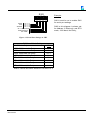
1
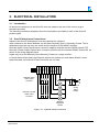
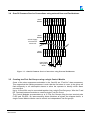
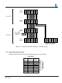
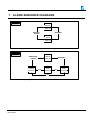
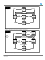
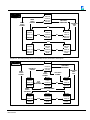
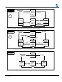
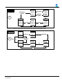
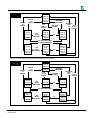
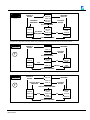
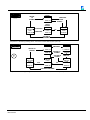
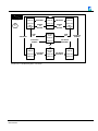
Omni30 Series
Alarm Annunciators
DATE
Aug 2002
Jan 2003
Mar2003
June 2011
REVISION
1
2
3
4
COMMENTS
Initial revision
Corrections for Production
Edited for distribution
Corrected Text on Sequence Diagrams
SOFTWARE COPY AVAILABLE
This manual is available in printed form or in Adobe Acrobat pdf format.
The Acrobat Portable Document File is named UMC1620AR03.pdf
COPYRIGHT AND PROTECTIVE NOTICES
1. The Copyright of this document and the associated drawings, is the property of Omniflex and
is issued on condition that it is not copied, reprinted or reproduced or transmitted in any form
or by any means, electronically, photocopying, mechanical or otherwise, nor its contents
disclosed, either wholly or in part, without the consent in writing of, or in accordance with the
conditions of a contract with Omniflex.
2. The publication of information in the document does not imply freedom from patent or other
protective rights of Omniflex or others.
3. Although every intention is made to ensure that performance figures and data are accurate the
company reserves the right to alter without notice any product or specification. Performance
figures and data must therefore be specifically confirmed by the company before they become
applicable to any tender, order or contract.
4.
5.
In the case of electrical components, enough data is included in the drawings to allow
maintenance of the equipment. However, if component availability or substitution information
is required please consult the factory for assistance, as it is impossible to include data on
every component in this document.
This product is sold without liability for consequential loss of any description.
Omni30 User Manual
UMC1620AR04
-2-
© Omniflex
SCOPE
This User Manual provides information necessary to install, configure and operate your
Omni30 product.
This manual covers the following product Model Numbers:
Model
Product
Description
C1620
Omni30/8
8 Way Alarm Module
Panel Mount (483mmW x 44.5mmH)
C1620-1
Omni30/8-SL
8 Way Alarm Module
19 inch Rack mount (483mmW x 44.5mmH)
C1621
Omni32/8
4 Way Alarm + Control Module
Panel Mount (483mmW x 44.5mmH)
C1621-1
Omni32/8-SL
4 Way Alarm + Control Module
19 inch Rack Mount (483mmW x 44.5mmH)
C1622
Omni33/8
8 Way Control Module
Panel Mount (483mmW x 44.5mmH)
C1622-1
Omni33/8-SL
C1623
Omni30/4
C1624
Omni33/4
8 Way Control Module
19 inch Rack Mount (483mmW x 44.5mmH)
4 Way Alarm Module
Panel Mount (267mmW x 44.5mmH)
Control Module
Panel Mount (267mmW x 44.5mmH)
Introduction
The OMNIFLEX Omni30 family is a range of alarm annunciators designed using the
OMNIFLEX Omni16c alarm annunciator technology, packaged in 10.5inch and 19inch
housings, in 4 and 8 way configurations.
All products in the range are available “off-the-shelf” with no factory customisation
required. Because these units are not built to order, spares holding and maintenance are
significantly reduced.
Alarm display options include long-life incandescent lamps for lowest initial cost, or highbright back-lit LED’s for best life cycle cost and lowest power consumption and reliability.
Display legends for the backlit displays are created by the user on any standard
laser/inkjet printer using software templates supplied with the product.
All popular configuration options are accomplished by switch settings externally available
on the unit.
Additional options include:
• 27 alarm sequences as standard for widest range of applications.
• Flash synchronisation between modules.
• A Software Configuration Utility for more advanced customisation.
Omni30 User Manual
UMC1620AR04
-3-
© Omniflex
•
Fully isolated RS232/422/485 Modbus © compatible serial port to interface to PLC, DCS,
or SCADA systems.
The Omni30/4 Panel Mount 4 point Alarm Annunciator.
The Omni30/8 Panel Mount 8 point Alarm Annunciator.
The Omni32/8 Panel Mount 4 point alarm & Control Module
The Omni33/4 Panel Mount Control Module
The Omni33/8 Panel Mount Control Module
Omni30 User Manual
UMC1620AR04
-4-
© Omniflex
Table of Contents
1. GENERAL DESCRIPTION ............................................................................................... 7
1.1 Standard Features ........................................................................................................ 7
1.2 Options available........................................................................................................... 7
1.3 Rear Views of the Omni30 Series products ................................................................ 7
2. MECHANICAL INSTALLATION ....................................................................................... 9
2.1 Mechanical Dimensions ................................................................................................ 9
2.2 Panel Mounting ............................................................................................................. 9
2.3 19 inch Rack Mounting ................................................................................................. 9
2.4 Installing Back-lit LED boards .................................................................................... 10
2.5 Installing Incandescent Lamps................................................................................... 10
2.6 Creating Window Legends for Back-lit Display Windows........................................ 10
2.6.1 Overview
................................................................................................................................................................ 10
2.6.2 Creating the Legend Film................................................................................................................................................. 10
2.7 Inserting Legends and Colour Filters into Back-lit Display Windows ..................... 11
2.7.1 Colour of Windows ......................................................................................................................................................... 11
2.7.2 Assembling Back-lit Display Windows ................................................................................................................................ 11
2.7.3 Removing Backlit Display Windows ................................................................................................................................... 12
3. ELECTRICAL INSTALLATION....................................................................................... 13
3.1 Introduction .................................................................................................................. 13
3.2 Omni30 Alarm Input Connections .............................................................................. 13
3.3 Omni30 Common Service Connections using an Omni30 Control Module........... 14
3.4 Omni30 Common Service Connections using external Horn and Pushbuttons .... 15
3.5 Creating two First Out Groups using a single Control Module................................ 15
3.6 Omni30 Serial Port Pinout .......................................................................................... 16
3.7 Power Requirements .................................................................................................. 17
4. CONFIGURING THE OMNI30 FOR OPERATION....................................................... 18
4.1 Introduction .................................................................................................................. 18
4.2 Modes of Operation .................................................................................................... 18
4.3 Selecting the alarm/display logic sequences ............................................................ 19
4.4 Selecting the Group Alarm Output Function ............................................................. 21
4.5 Selecting the Lamp Status ......................................................................................... 21
4.6 Selecting Time Delays ................................................................................................ 21
4.6.1 Omni30 Fast and Slow Timers .......................................................................................................................................... 22
4.6.2 Explanation of Timer Operation in a Timer Sequence ........................................................................................................... 22
4.7 Selecting Serial Port Settings .................................................................................... 22
5. OPERATION .................................................................................................................... 25
5.1 Power-up...................................................................................................................... 25
5.2 Normal Operation ........................................................................................................ 25
5.3 Test Functions ............................................................................................................. 25
Omni30 User Manual
UMC1620AR04
-5-
© Omniflex
5.3.1 Overview of the Test Functions......................................................................................................................................... 25
5.3.2 Pressing the Test Button ................................................................................................................................................. 25
5.3.3 Fault Indication on Circuit Test.......................................................................................................................................... 26
5.3.4 Manually invoking the Circuit Test Function. ....................................................................................................................... 26
5.3.5 The “Marching Sequence” Circuit Test Display .................................................................................................................... 26
6. SPECIFICATIONS ........................................................................................................... 28
7. ALARM SEQUENCE DIAGRAMS.................................................................................. 31
8. MODBUS REGISTER LAYOUT ..................................................................................... 44
Omni30 User Manual
UMC1620AR04
-6-
© Omniflex
1. GENERAL DESCRIPTION
1.1
Standard Features
•
•
•
•
•
•
•
•
1.2
Options available
•
•
1.3
Standard 4 and 8 point modules allow integral systems from 4 to 128 points to be
constructed by the user.
All products in the range are supplied off-the-shelf with no factory customisation
required, to minimise spares holding.
Panel mounted display options include long-life incandescent lamps or high-bright
back-lit LED’s.
User-created display legends on standard laser/inkjet printer using software templates
supplied – no window engraving required.
Plug-in terminals for easy installation and maintenance.
Switch selectable Normally Open or Normally Closed input contact sense selection
while installed. No dismantling required.
27 switch selectable alarm sequences built in, covering most alarm annunciator
specifications and configurations.
24Volt dc powered.
Fully isolated RS232/422/485 Modbus © compatible serial port to interface to PLC,
DCS, or SCADA systems.
Advanced Software Configuration Utility to configure the Omni30 in “SOFT-SET” mode
for more specialised applications.
Rear Views of the Omni30 Series products
Figure 1-1 – Panel Mount Omni30/4 Rear View
Figure 1-2 – Panel Mount Omni33/4 Rear View
Omni30 User Manual
UMC1620AR04
-7-
© Omniflex
Omni30
Figure 1-3 – Omni30/8 Rear View
Omni32
Figure 1-4 – Omni32/8 Rear View
Omni33
Figure 1-5 – Omni33/8 Rear View
Omni30 User Manual
UMC1620AR04
-8-
© Omniflex
2. MECHANICAL INSTALLATION
2.1
Mechanical Dimensions
Figure 2-1 –Omni30 Mechanical Dimensions
2.2
Panel Mounting
The panel mounted Omni30 series units may be mounted individually or in groups in a
single cut-out in the panel. Each annunciator is mounted using its own mounting studs. See
the Mechanical Dimensions above for detailed requirements for the cutout.
If incandescent lamps are installed in the windows in these units, then the maximum
number of units recommended in a single cut-out is 6 units to prevent excessive heat buildup.
2.3
19 inch Rack Mounting
Some of the Omni30 Series units are available in 19inch Rack mountable enclosures.
Omni30 User Manual
UMC1620AR04
-9-
All 19 inch Rack mounted units are 1U (44.45mm) in height.
If incandescent lamps are installed in the windows in these units, then the maximum
number of units recommended to stack without a ventilation gap is 6 units to prevent
excessive heat build-up.
2.4
Installing Back-lit LED boards
Back-lit LED boards are installed through the front windows of the unit.
To install an LED board in a window, follow this procedure:
1. Snap out the relevant clear plastic window using slot in the centre (see 2.7.3).
2. Remove any lamps that may already be installed. (Backlit LED boards can be installed
in units that have incandescent lamp holders installed, but only after the bulbs have
been removed.)
3. Using a pair of long-nose pliers, grip the backlit LED board by the central connector, and
carefully insert on to the gold pins located in the centre of the window.
4. Press the board firmly into position so that the white locating spacer clips into the
locating hole in the back of the window.
Markings on the LED board indicate the correct insertion orientation. If an LED board is
inserted the wrong way around, it will not work, but no damage will be done.
2.5
Installing Incandescent Lamps
If the Omni30 Alarm unit has incandescent lamp-holders fitted, then the incandescent lamps
may be fitted and changed through the front windows.
To install the lampholders themselves, however, the Lamp display Assembly must be
removed from the main housing. Consult your nearest OMNIFLEX distributor for assistance
in installing incandescent lamp holders.
2.6
Creating Window Legends for Back-lit Display Windows
2.6.1 Overview
Legends are created for the Omni30 on a laser or inkjet printer using the software templates
provided with the product.
Templates for popular programs are supplied on a 3,5” ‘stiffy’ diskette with your unit. There
are templates for Microsoft Word and Microsoft PowerPoint to run on an IBM compatible
computer running the Windows95, Windows 98 or Windows NT/2000/XP operating
systems. There is also a README.TXT file on this disk. Read this first to see which
versions of program are compatible with these templates.
2.6.2 Creating the Legend Film
To create the legend film, follow this procedure:
1. Start the application program you wish to use.
2. Open the appropriate template from the ‘stiffy diskette’ supplied.
3. Fill in your legend details in this template.
4. Print the legends created onto overhead transparency film (the type used for overhead
presentations). A sheet is included with the product.
Omni30 User Manual
UMC1620AR04
- 10 -
5. Cut along the cut marks which will print onto the film to produce the number of individual
legends required.
6. Insert them into the Omni30 as described in section 2.7.
Please note that the supplied templates have been tested on a wide range of printers. Your
particular printer may scale the image slightly differently. While the front grid markings
should accommodate this tolerance, in exceptional circumstances you may have to alter the
grid spacing on the template supplied. This needs to be done once only and will then be set
for your printer.
2.7
Inserting Legends and Colour Filters into Back-lit Display Windows
2.7.1 Colour of Windows
If Back-lit LED boards are used, then the colour of the window can be set by the
choice of LED lamp board colour, and no additional colour filters are required.
If incandescent lamps or white LED boards are used, then a coloured window filter
can be inserted into the window to provide the required lamp colour.
These coloured filters are provided in a kit of assorted colours supplied with the
product.
Each kit of coloured filters contains the following:
C1663 Colour Filter Kit Contents
8 Red Filters
8 Yellow Filters
8 Green Filters
4 Blue Filters
Additional Colour Filter Kits may be ordered as desired by quoting Model Number
C1663.
2.7.2 Assembling Back-lit Display Windows
Assemble back-lit windows into the Omni30 as follows:
1. Assemble each window as shown in Figure 2-2 Backlit Window Order of Assembly.
2. Snap the assembled window into position in the Omni30 Alarm unit.
Omni30 User Manual
UMC1620AR04
- 11 -
Rough surface
this side
Legend Film
Colour Filter
(if required)
White Diffuser
Figure 2-2 Backlit Window Order of Assembly
2.7.3 Removing Backlit Display Windows
Windows may be removed by inserting a screwdriver in the slot provided on the top or
bottom of the clear window to lever it gently out.
The Diffuser, legend and coloured filter may be removed from the window by pressing
the window down on to a flat surface such as a desk top. This diffuser, coloured filter
and legend will pop out.
Omni30 User Manual
UMC1620AR04
- 12 -
3. ELECTRICAL INSTALLATION
3.1
Introduction
All electrical connections to the Omni30 units are made on the rear of the unit on plug-in
terminals provided.
The following connection diagrams show the terminations provided on each of the Omni30
product types:
3.2
Omni30 Alarm Input Connections
Inputs to the Omni30 Annunciator must be potential free contacts.
Input contacts to the Alarm Modules can be either Normally Open or Normally Closed. This is
dependent upon the way they are wired, and the position of the NO/NC switches.
Normally Open Contact Inputs have a common negative with the relevant NO/NC switch OFF.
Normally Closed Contact Inputs have a common positive with the relevant NO/NC Switch ON, as
shown in the wiring diagram below.
Inputs may be mixed Normally Open/Normally Closed on a single module.
1 2 3 4
ON
NC+
NOIP 4
IP 3
IP 2
IP 1
LMP 4
LMP 3
LMP 2
LMP 1
GP
+24V
A Group Alarm Output and Lamp Repeat outputs are optional on each Alarm Module. Leave
these terminals unconnected if these functions are not used.
:
On for N.C
Normally Open
Alarm Input
Contacts
Optional
Group
Alarm
Output
Normally Closed
Alarm Input
Contacts
Optional
Repeated
Lamps
Figure 3-1 –Omni30 Alarm Connections
Omni30 User Manual
UMC1620AR04
- 13 -
Alarm
Module
Alarm
Module
24V+
24V24V+
24VHORN
24VTEST
ACK
24V+
RESET
P
DP
Omni30 Common Service Connections using an Omni30 Control Module
24V+
24V24V+
24VHORN
24VTEST
ACK
24V+
RESET
P
DP
3.3
GP
24V+
NC
NO
COM
P2
DP2
24V+
L
Control
Module
24V+
24V24V+
24VHORN
24VTEST
ACK
24V+
RESET
P
DP
24Vdc Supply
connected to
centre unit
Optional Group Repeat
Outputs etc. (see text)
Figure 3-2 – Omni30 Common Service Connections using an Omni30/4 or 30/8 Control Module
NB: Throughout this manual ACKNOWLEDGE and ACCEPT are used interchangeably.
Note that P and DP connections correspond to connections of Rochester UC30 series of
annunciators. This compatibility is achieved by setting internal links as follows:
a. On Control Board (inside Control Module) set Links 3, 5, 6, 8 to A-B (as marked).
b. On Main Input Board (main PCB inside the Alarm Module, e.g. Omni30/8) set Links 3, 8
to A-B.
If these Links are left set to C-D, then the P and DP connections operate as described in
this manual, namely:
a. Terminal DP operates as FlashSync (flash rate of all lamps in all interconnected Omni30
units is synchronised).
b. Terminal P operates as FirstOut input/output.
The interconnection of units is still accomplished as per diagram above.
Omni30 User Manual
UMC1620AR04
- 14 -
Alarm
Module
Alarm
Module
24V+
24V24V+
24VHORN
24VTEST
ACK
24V+
RESET
P
DP
Omni30 Common Service Connections using external Horn and Pushbuttons
24V+
24V24V+
24VHORN
24VTEST
ACK
24V+
RESET
P
DP
3.4
Test
Ack
Horn Relay
with flyback
diode
Reset
Alarm
Module
24V+
24V24V+
24VHORN
24VTEST
ACK
24V+
RESET
P
DP
24Vdc Supply
connected to
centre unit
Figure 3-3 – Omni30 Common Service Connections using External Pushbuttons
3.5
Creating two First Out Groups using a single Control Module
Some of the alarm sequences selectable in the Omni30 are “First-Out” alarm sequences.
This means that the flashing sequence is such that the first alarm to occur in the group will
flash differently to all subsequent alarms to allow the operator to identify which alarm
occurred first.
Up to 16 Omni30’s may be connected together into a single First-Out group. Wire the P and
DP Terminals between modules to create a single First Out Group.
The Control Modules accommodate up to 2 First Out Groups using the two terminal pairs
P+DP and P2+DP2. By interconnecting Alarm Modules as shown the diagram below, a
single Control Module can be used to control two independent First Out groups.
Omni30 User Manual
UMC1620AR04
- 15 -
24V+
24V24V+
24VHORN
24VTEST
ACK
24V+
RESET
P
DP
Alarm
Module
Alarm
Module
Optional Group Repeat
Outputs etc. (see text)
Figure 3-4 – Omni30 connections showing two First Out Groups
3.6
Omni30 Serial Port Pinout
If fitted with the Serial Port Option the Serial connections are as follows:
Omni-8/16C
DB9
Pin
1
2
3
4
5
6
7
8
9
Omni30 User Manual
UMC1620AR04
RS232
RxD
TxD
RS485
RxD+
RxD-
1
TxD+
GND
GND
Vcc(iso) Vcc (iso)
9
5
TxD-
- 16 -
6
GP
24V+
P2
DP2
24V+
L
Control
Module
NC
NO
COM
24Vdc Supply
connected to
centre unit
24V+
24V24V+
24VHORN
24VTEST
ACK
24V+
RESET
P
DP
First Group 1
24V+
24V24V+
24VHORN
24VTEST
ACK
24V+
RESET
P
DP
Alarm
Module
24V+
24V24V+
24VHORN
24VTEST
ACK
24V+
RESET
P
DP
First Group 2
NB! Once the Serial Port (DB9) Option has been fitted the Serial Jack plug facility
normally used to configure the annunciator is disabled. Configuration must be done
through the DB9 Serial Port once it is fitted to an Omni30.
3.7
Power Requirements
The Omni30 range is 24Volt dc powered.
The table below gives the maximum current requirement of each of the products in the
range.
C1620
C1621
C1622
C1623
C1624
Model
Omni30/8
8 Way Alarm
Omni32/8
4 Way Alarm + Control
Omni33/8
Control
Omni30/4
4 Way Alarm
Max Current Consumption at 24Volts dc
1.1 Amps
0.8 Amps
0.2 Amps
0.6 Amps
Omni33/4
Control
0.2 Amps
Table 3-1 Omni30 Power Consumption
Note: This power consumption excludes the requirements of external Horns or displays used in
conjunction with these products, but is given with all Lamps on.
Omni30 User Manual
UMC1620AR04
- 17 -
4. CONFIGURING THE OMNI30 FOR OPERATION
4.1
Introduction
The Omni30 is configured by means of two 8-way “set-up” switches marked SW1 and SW2.
These are located on the left hand side of each Alarm Module (looking from the back).
Each 8-way switch has 8 individual miniature switches, numbered from 1 to 8. Each of
these miniature switches can be referred to individually: for example, the 8 miniature
switches on SW1 are referred to as SW1-1 to SW1-8.
4.2
Modes of Operation
SW1 and SW2 are used to set the operational configuration of the Omni30.
The Omni30 can be set into one of two modes of operation:
“SWITCH-SET” mode or “SOFT-SET” mode.
In “SWITCH-SET” mode, the entire operation of the unit is set by selections on these mode
switches.
In “SOFT-SET” mode, the operation of the product is set via the programming port or (serial
port if fitted) on the rear of the unit using the optional Software Configuration Software.
The product is put into “SOFT-SET” mode by a specific selection on the mode switch SW1.
(SW1-1 to SW1-8 set on). Some features are only available via programming or serial port.
This manual covers the “SWITCH-SET” configuration (for SOFT-SET configuration see the
on-line help in the Omni16C Configuration template supplied with the Omniset
Configuration Utility).
SOFT-SET mode offers the optimum in flexibility whilst SWITCH-SET Mode offers Omni16a
and b style functionality and limited options. The table below summarises the capabilities of
each mode and the limitations.
COMPARISON OF DIP SWITCH MODE VERSUS SOFTSET MODE
CONFIGURATION OPTIONS
CONFIGURATION OPTION
DIP SWITCH
SET MODE
SOFT-SET
MODE
Alarm Sequences
Select Sequence number from Table 4-1. DIP switches must
be set to Sequence 31 on SW1 for this register to be
recognised, otherwise the DIP switch setting is used.
Sets :
Input 1-8
Each Input
individually
set
Timers
Setup Timer Setting:
Input 1-8
Input delay timer set per input. One input per byte.
Single Timer for all
Alarm Points
Each Alarm Point
individually
set
Timer
Setup Timer Resolution
Group Alarm Outputs
Yes
Yes
Setup Relay Output Function
No
Yes
Preset as Group
Alarm
Choose option for
each
Omni30 User Manual
UMC1620AR04
- 18 -
COMPARISON OF DIP SWITCH MODE VERSUS SOFTSET MODE
CONFIGURATION OPTIONS
CONFIGURATION OPTION
DIP SWITCH
SET MODE
SOFT-SET
MODE
Lamp Sense
Yes
Yes
Bit 0: Pushbutton Edge/Level Detection Option:
Bit 1: Auto ACK on Startup Option: Turn off running light
sequence
No
No
Yes
Yes
Bit 2: Inhibit Input operation Option:N/A in Omni30
Note: Only applies when SW1-8 is ON.
Bit 3: Repeat Output operation Option: Repeat Input status or
Repeat Alarm status (via serial port only)
Bit 4: Repeat Sense operation Option: Normally deenergised, Normally energised (fail safe) (via serial port only)
Yes
Yes
No
Yes
No
Yes
Setup Lamp Sense
All Lamps Normal Sense or Lamps Reversed Sense.
Note: This setting only applies when SW1-8 is ON.
System Operation
Bit 5-15: Reserved
4.3
Selecting the alarm/display logic sequences
There are two fundamental variations to the switch settings chosen, dependent upon the
settings of SW1-8 and SW2-7
First decide upon the setting of these two switches before proceeding to select the other
switch settings.
These are shown in the following table:
A
SW1-8
Off
SW2-7
Off
B
Off
On
C
On
-
SW1-1 to 5
Sets sequence for
inputs 1-4
Sets sequence for
inputs 1-8
Sets sequence for
inputs 1-8
SW2-1 to 5
Sets sequence for
inputs 5-8
Sets Timer value
for all input timers.
Sets Serial Port
address and R/W
SW2-6 to 8
Operate as per
Table 4-1
Operate as per
Table 4-1
Sets Baud Rate
etc.
NOTES:
1. Settings A and B are compatible with the previous Omni16a and Omni16b products.
2. When SW1-8 and SW2-7 are set as per A or B in the table above, the serial port
address defaults to 2, and the communications settings default to ASCII 9600 baud.
3. When SW1-8 is ON as per C in the table above, then the following default settings
apply:
Inhibit Contact Sense – not used in Omni30.
Lamp sense is set to normal.
Omni30 User Manual
UMC1620AR04
- 19 -
Table 4-1: The Sequence Switch Settings
SEQUENCE
SWITCHES
SW1
SEQ.
NO.
1
2
3
4
5
SW2
6
7
8
1
2
3
4
5
6
7
8
DESCRIPTION
T
ISA
DESIGNATION
TIME DELAY ON...
0
0 0 0 0
0
1
1 0 0 0
0
2
0 1 0 0
0
3
1 1 0 0
0
4
0 0 1 0
0
5
1 0 1 0
0
6
0 1 1 0
0
7
1 1 1 0
0
8
0 0 0 1
0
9
1 0 0 1
0
10
0 1 0 1
0
11
1 1 0 1
0
12
0 0 1 1
0
13
1 0 1 1
0
14
1 0 0 0
1
18
0 1 0 0
1
21
1 0 1 0
1
23
1 1 1 0
1
24
0 0 0 1
1
25
1 0 0 1
1
26
0 1 0 1
1
27
1 1 0 1
1
28
1 0 1 1
1
31
1 1 1 1
1 1
FOLLOWS INPUT
0
FOLLOWS ALARM
1
STATE
ACTS AS RINGBACK
0
HORN
ACTS AS MRF
1
(REFLASH)
SW2=TIMERS/SEQUENCE 9-16
SW2=SERIAL PORT SETTINGS
CLOSE TO INHIBIT
OPEN TO INHIBIT
TIMERS OFF
TIMERS ON
LAMP SENSE NORMAL
LAMP SENSE REVERSE
Omni30 User Manual
UMC1620AR04
1
0
0
1
0
1
0
1
0
1
0
1
0
1
0
1
0
1
1
0
1
1
0
1
0
1
1
0
0
0
1
1
0
0
1
1
0
0
1
1
0
0
0
1
0
1
0
0
1
1
0
1
0
0
0
0
1
1
1
1
0
0
0
0
1
1
0
0
1
1
0
0
0
0
1
0
0
0
0
0
0
0
0
0
1
1
1
1
1
1
0
0
0
0
1
1
1
1
1
0
0
0
0
0
0
0
0
0
0
0
0
0
0
0
1
1
1
1
1
1
1
1
1
1
0
0
1
FACTORY TEST MODE
LAMP FOLLOWS INPUT
MOMENTARY (FLEETING) ALARM
MOMENTARY ALARM, MANUAL RESET
MOMENTARY ALARM, MANUAL RESET WITH RINGBACK
MULTIPLE GROUP, FIRST OUT MANUAL RESET
FIRST OUT, AUTO RESET, F.O. RESET INTERLOCK
SINGLE GROUP, 1st OUT, MANUAL RESET, 1st UP CONTINUOUS FLASH
1st OUT, MANUAL RESET WITH NO SUBSEQUENT ALARM STATE ACCEPT PUSHBUTTON
MOMENTARY (FLEETING) ALARM MANUAL RESET
MOMENTAR RY (FLEETING) ALARM MANUAL RESET
MOMENTARY (FLEETING) ALARM MANUAL RESET FOR MOTOR ALARMS
MOMENTARY (FLEETING) ALARM
PULSE MONITORING ALARM WITH MANUAL RESET
MOMENTARY (FLEETING ALARM), MANUAL RESET, WITH RINGBACK.
MOMENTARY (FLEETING) ALARM AUTO RESET
MULTIPLE GROUP, FIRST OUT, AUTO RESET
SINGLE GROUP, 1st OUT, AUTO RESET, 1st UP CONTINUOUS FLASH
MULTIPLE GROUP, FIRST OUT, AUTO RESET, NO SUBSEQUENT ALARM STATE, ACCEPT PUSH BUTTON
MOMENTARY (FLEETING) ALARM AUTO RESET
MOMENTARY FLEETING ALARM, AUTO RESET
MOMENTARY ALARM AUTO RESET FOR MOTOR ALARMS
PULSE MONITORING ALARM AUTO RESET
SOFT-SET MODE. ALL SETTINGS ARE SET VIA SOFTWARE. (Refer Table 4-2)
FUNCTION OF GROUP ALARM ON RELAY 3
(G.A.)
1
-M-1
A-1-4
R-1-10
F2M-1
F3A-1-3
-F1M-1
------
-INPUTS
INPUTS
INPUTS
---INPUTS
HORN
REFLASH
INPUTS
RETURN TO NORMAL
--
-F2A-1
-F1A-1
------
INPUTS
---HORN
NO ACTION REALARM
INPUT
---
NOTE:
In the above sequences, the switch
sense is as follows:
1
0
1
#
#
#
#
#
*
*
*
*
*
#
0
1
#
#
0
1
0
1
When SW1-8 is OFF, SW2 sets functions as shown in this table.
When SW1-8 is ON , SW2 sets Serial Port Address and Baud Rate etc. See Section 4.7
With SW1-8 OFF, when SW2-6 is OFF, set Inhibit Input low to stop further alarms (serial port only)
With SW1-8 ON, when SW2-6 is ON, set Inhibit Input high to stop further alarms (serial port only)
With SW1-8 OFF and SW2-7 OFF: Timers are off, and SW2-1 to SW2-5 set the sequence of inputs 9-16
With SW1-8 OFF and SW2-7 ON: SW2-1 to SW2-5 sets Time-out value. See Figure 4-1
With SW1-8 OFF, when SW2-8 is OFF: Lamp outputs operate normally
With SW1-8 OFF when SW2-8 is on: Lamp outputs operate in reverse sense. i.e. On instead of off and v.v.
- 20 -
“1” = switch in on position
“0” = switch in off position
© Omniflex
4.4
Selecting the Group Alarm Output Function
The Group Alarm (G.A.) output provides a transistor switch on terminal GP of each Alarm Module.
SW1-6 and SW1-7 are used to set the mode of operation of this output.
There are four modes to choose from:
1. Relay follows input
The relay is normally energised.
Any abnormal input will de-energise the relay. The relay will re-energise when all inputs
return to their normal states, regardless of the state of the alarm lamps.
This is useful for tracking the actual state of the inputs. Any abnormal input will cause the
relay to be de-energised.
2. Relay follows alarm state
The relay is normally energised.
Any alarm state will de-energise the relay. The relay will return to normal when all alarm
states have returned to normal. (i.e. the alarms have been acknowledged by the operator
and the entire display is off)
This is useful for tracking the actions of a local operator in clearing the problem. If a ‘fleeting’
alarm sequence is chosen, the relay will remain de-energised until the operator clears the
display, even though the input contact may have already returned to the normal state.
3. Relay acts as ring-back horn
The relay is normally de-energised.
The G.A. relay will energise when any abnormal input returns to normal. The RESET
pushbutton must be depressed to return the G.A. to its normal state.
(This G.A. type can be used to alert an operator to the fact that an alarm has returned to its
normal state).
4. Relay acts in Multiple Reflash Mode
The relay is energised with all inputs in their normal state.
The relay is de-energised by the first input changing to the abnormal state.
Upon each subsequent input changing to the abnormal state, the relay will momentarily
energise (for about 1 second), then return to the de-energised state.
This is useful when the relay contact is used for example to trigger a dial up alarm, and if
subsequent inputs going into alarm must also trigger the dial-up alarm.
Referring to Table 4-1: The Sequence Switch Settings, select one of the 4 relay modes by
setting switches SW1-6 and SW1-7 to the appropriate positions.
4.5
Selecting the Lamp Status
The lamp status of the display windows may be selected on SW2-8 to give the following:
NORMAL:
lamps OFF when inputs are normal, ON when inputs are abnormal.
REVERSE:
lamps ON when inputs are normal, OFF when inputs are abnormal.
Note: SW1-8 must be off for this selection to be operational. When SW1-8 is on, SW2-6 is
reassigned, and the lamp status defaults to Normal.
4.6
Selecting Time Delays
The Omni30 Alarm modules have a timer associated with each alarm point.
These timers are used with special Timer sequences. A large “T” in the sequence diagram in
Section 7 identifies these sequences.
There are two methods of selecting a time delay setting for these sequences:
Omni30 User Manual
UMC1620AR04
- 21 -
© Omniflex
1. The timers may be set using SW2-1 to SW2-5. This method is invoked by switching SW27 on. This method is recommended when all timers have the same time setting.
2. Programming the memory of the Omni30 using the optional Software Configuration Utility
will set each input timer individually. If this memory is not programmed, then the timers
default to the switch settings. This method should be used when different input timer
settings are required.
SW2
1 2 3
ON
4 5 6 7 8
Example:
SW1-8 must be off to enable SW2
as time setting.
On = +1
On = +2
On = +4
On = +8
On = +16
Inhibit
Timer On/Off
On=Slow; Off = Fast
SW2 in this diagram shown set for
0.5 seconds.
Slow = Uses the Slow timer i.e. 1 sec increments
Fast = Uses the Fast timer i.e. 1/10 sec increments
Figure 4-1 Setting Time Delays on SW2
4.6.1 Omni30 Fast and Slow Timers
Figure 4-1 above shows the use of the Fast and Slow timer. These timers allow the
user the most flexible timing options. For very short timing durations, the Fast timer
should be used. This timer counts time in units of 100ms or 1/10 of seconds.
For longer time periods, the Slow timer should be used. This timer is derived from the
Fast timer and therefore counts time in multiples of the Fast timer. The default setting of
the Slow timer is to count time in seconds. It is possible to alter the timing mechanism
of the Slow timer to count in larger units of time via the programming port.
4.6.2 Explanation of Timer Operation in a Timer Sequence
With reference to any one of the special timer sequences:
When the alarm point moves from a state where the timer is stopped to a state where
the timer is running, the timer will be started.
When the alarm point moves from a state where the timer is running to a state where
the timer is also running, the timer is allowed to continue timing.
When an alarm point moves from a state where the timer is running to a state where
the timer is stopped, the timer is put into the timed-out (stopped) state.
4.7
Selecting Serial Port Settings
The Omni30 can be equipped with an optional RS232/485 serial port. This port supports the
Modbus protocol. In Switch set mode, inputs and outputs can be read via the serial port using
Omni30 User Manual
UMC1620AR04
- 22 -
© Omniflex
standard Modbus © commands. Please refer to Section 8 for the layout of Modbus Registers
that are available in the Omni30.
When the unit is in Switch set mode (refer to settings A or B of section 4.3), the unit may be
accessed via Modbus without changing the dipswitch settings at all. In this mode,
communications settings are fixed as follows:
Modbus Settings without changing SW1 or SW2
Modbus Slave Address
2
Comms settings
ASCII; 9600 baud; No Parity
Table 4-1a – Serial Port Settings with no change to SW1 or SW2
This form of access is made available for setup of input timer values and does allow users to
read status information for diagnostic purposes.
In applications where the Modbus Slave address and/or comms settings are to be different
from the table above then set SW1-8 ON to enable SW2 for additional serial port settings.
Omni30 User Manual
UMC1620AR04
- 23 -
© Omniflex
SW2
Example:
1 2 3 4 5 6 7 8
ON
SW1-8 must be on to enable SW2
for serial port settings.
Serial
On = +1
Port
On = +2
On = +4
Address
On = +8
On = Write Allowed
Mode Settings
see Table
SW2 in this diagram is shown set
for Address 2; Read only; and RTU
mode, 1200 baud, No Parity,
Figure 4-2 Serial Port Settings on SW2
SW2-6 to 8 Mode Settings
(0 = Off ; 1 = On)
6:7:8
ASCII; 9600 baud; No Parity
ASCII; 4800 baud; No Parity
0:0:1
1:0:1
ASCII; 2400 baud; No Parity
0:1:1
ASCII; 1200 baud; No Parity
RTU; 9600 baud; No Parity
1:1:1
0:0:0
RTU; 4800 baud; No Parity
1:0:0
RTU; 2400 baud; No Parity
RTU; 1200 baud; No Parity
0:1:0
1:1:0
Table 4-2 Serial Port Mode Parameters on SW2-6 to 8
Omni30 User Manual
UMC1620AR04
- 24 -
© Omniflex
5. OPERATION
5.1
Power-up
When power is applied to the Omni30, the unit commences an automatic, built-in circuit test
routine. This results in the unit sounding the audible for approximately half a second followed by
the cyclic illumination of each lamp in turn starting at lamp 1 to the last lamp and back to 1 again
etc. in a “marching sequence”.
If no internal faults are detected in the unit, then this test mode display continues until the ACCEPT
Pushbutton is pressed or until an input changes to the alarm state.
If an internal fault is detected, then the unit will display a fault indication by continuously flashing
one of the lamps. If this occurs, then the unit must be sent for service.
If a new alarm occurs while the Omni30 is in this test routine, the unit will immediately revert to its
normal mode of operation and will deal with the alarm state according to the pre-selected alarm
sequence.
5.2
Normal Operation
During the normal operation, the Omni30 will deal with any alarm states according to its pre-set
alarm sequences. (The instructions for setting-up these sequences are given in section 4.3).
Section 7 provides detailed block diagrams for the function of each alarm sequence.
When an alarm condition occurs and the horn sounds, the operator should depress the relevant
pushbuttons, where necessary, according to the pre-selected alarm sequence.
When the Omni30 is put into its test routine by depressing the TEST pushbutton, any existing
alarm states are “remembered” and the alarm annunciator will revert to its previous state when it
returns to its normal mode of operation.
If a new alarm state occurs while the Omni30 is performing its test routine, the unit will immediately
revert to its normal mode of operation and deal with the alarm state according to the pre-selected
alarm sequence.
5.3
Test Functions
5.3.1 Overview of the Test Functions
The Test button operates as a combined lamp test and circuit test function.
No information is lost during the entire test routine, and each alarm display returns to the
exact state it was in before the test.
5.3.2 Pressing the Test Button
When the Test button is pressed, the unit checks the results of its regular full circuit test, and
if all checks performed pass, then a conventional lamp test is performed, by illuminating all of
the lamps while the Lamp Test Pushbutton is held down. When the Test pushbutton is
released, the Omni30 reverts to the state it was in before the Test button was pushed.
If the circuit Test fails then the unit enters its “marching sequence” test routine described in
Section 5.3.5 and the test failure code will be displayed by flashing one of the lamps
continuously.
In this way, the display/annunciator Test button acts both as a Lamp Test and Circuit
Function.
Omni30 User Manual
UMC1620AR04
- 25 -
© Omniflex
5.3.3 Fault Indication on Circuit Test
If a fault is found in one of the tests performed, then the unit enters its full “marching lamp
sequence”, with, in addition, one or more of the lamps flashing continuously to indicate the
fault located. This is described in detail in Section 5.3.5
5.3.4 Manually invoking the Circuit Test Function (only through serial port).
As a confidence measure, the unit may be placed in the full “marching sequence” Circuit Test
Mode at any time by activating Silence and then Test.
See section 5.3.5
5.3.5 The “Marching Sequence” Circuit Test Display
This routine is entered upon the following conditions:
• Upon power up.
• If the Test button is pressed and a fault is detected in the unit.
• Any time during normal operation, if the unit during its regular self-test routines detects a
fault.
This test routine begins by activating the horn output circuit for approximately one second.
The operator should therefore check that the horn sounds for this short period.
Immediately after this half-second period, if the Omni30 is functioning correctly, the following
visual indication will occur:
The display will begin a “marching light” sequence, with each display window illuminating and
then extinguishing, one at a time, starting with the display point 1 (left-hand window) and
ending with the display point 8 (right-hand window). All display windows will then remain
extinguished for a brief moment.
The “marching” sequence will then begin again, and this procedure of “marching” sequence
followed by the brief “blank” display period will be repeated continuously until the ACCEPT
pushbutton is depressed, or until an input changes state.
This marching sequence indicates that the alarm annunciator has passed all its own internal
tests and is functioning correctly. If the lamp display exhibits any other pattern then a fault
has been detected, and the unit should be returned for service.
To exit the test mode and begin normal operation, the ACCEPT pushbutton should be
pressed.
The pushbuttons may also be tested in this mode:
If the ACCEPT button is depressed - the annunciator reverts to normal operation.
If the RESET button is depressed - lamp No. 3 flashes continuously.
If the TEST button is depressed - lamp No. 4 flashes continuously.
If any other lamp flashes continuously, then the unit has detected a fault and must be
returned to the factory for service.
If a new alarm occurs while the Omni30 is in this test routine, the unit will immediately revert
to its normal mode of operation and will deal with the alarm state according to the preselected alarm sequence.
It is possible under some circumstances to continue to operate the Omni30 even after a fault
has been detected. The table below will assist in diagnosing the fault found.
Omni30 User Manual
UMC1620AR04
- 26 -
© Omniflex
Table 5-1 Fault diagnosis during Circuit Test
Display
Window No.
1
FAULT SYMPTOM
POSSIBLE CAUSE
FLASHING
during “Marching Sequence”
STEADY ON
during “Marching Sequence”, and stays ON
during “Blank” display period.
during “Marching Sequence”, and stays
OFF during “Blank” display period.
during “Marching Sequence”
SIL input (serial port) stuck in ON
state
Window No. 1 has lamp output
circuit fault.
Window No. 1 has lamp failure or
output circuit fault.
ACC pushbutton held down, or stuck
in ON state (this condition must have
been present BEFORE the CCT.
TEST mode was initiated)
Window No. 2 has lamp output
circuit fault.
Window No. 2 has lamp failure or
output circuit fault.
RESET pushbutton held down, or
stuck in ON state.
Window No. 3 has lamp output
circuit fault.
Window No. 3 has lamp failure or
lamp output circuit fault.
TEST pushbutton held down, or
stuck in ON state.
Window No. 4 has lamp output
circuit fault.
Window No. 4 has lamp failure or
lamp output circuit fault.
STEADY
OFF
FLASHING
2
STEADY ON
STEADY
OFF
FLASHING
3
STEADY ON
STEADY
OFF
FLASHING
4
STEADY ON
STEADY
OFF
STEADY ON
ANY
OTHER
LAMP
STEADY
OFF
1,2,3,4,6
STEADY ON
1,2,3,4
STEADY ON
1,2,3,4,5,6
STEADY ON
1,2,3,4,7
STEADY ON
Omni30 User Manual
UMC1620AR04
during “Marching Sequence”, and stays ON
during “Blank” display period.
during “Marching Sequence”, and stays
OFF during “Blank” display period.
during “Marching Sequence”
during “Marching Sequence”, and stays ON
during “Blank” display period
during “Marching Sequence”, and stays
OFF during “Blank” display period
during “Marching Sequence”
during “Marching Sequence”, and stays ON
during “Blank” display period.
during “Marching Sequence”, and stays
OFF during “Blank” display period.
during “Marching Sequence”, and stays ON
during “Blank” display period
During “Marching Sequence”, and stays
OFF during “Blank” display period.
Window has lamp output circuit fault.
During “Blank” display period but OFF
during “Marching Sequence”
During “Marching Sequence”
Fault detected on one of the INPUT
logic circuits
Fault detected on the SPI bus OR all
pushbuttons stuck ON
Fault detected on the SPI bus
During “Blank” display period but OFF
during “Marching Sequence”
During “Blank” display period but OFF
during “Marching Sequence”
- 27 -
Window has lamp failure or lamp
output circuit fault.
Fault detected with the on-board
EEPROM
© Omniflex
6. SPECIFICATIONS
Power Supply Options
Voltage
24Vdc
Isolation
PSU to inputs
None
Max dc Ripple
10% pk. to pk.
Current Consumption
See Section 3.7 of this manual
Alarm/Display Inputs - Non Isolated
Type
Potential Free Contacts
Switch to +24volts for NC
Switch to 0V for NO
Contact Sens e
User Selectable Normally Open or Closed on rear of unit on DIP
switch and by wiring of each iput.
Max. open circuit voltage
28Vdc
Max. closed circuit current
5mA per input circuit
Max. Loop Resistance to detect closed contact
1000 ohms
Min. Loop Resistance to detect open contact
200 kohms
Input Scan Rate
4 milliseconds with 8millisecond filter. Inputs must be stable for
at least 8 milliseconds for a change of state to be detected.
Wire size
1.5mm2 (17SWG/15.5SWG) max.
Connections
Via plug-in Terminals
Alarm Sequences
Quantity
: 27 (user selectable by set-up switches)
ISA types
M-1, A-1, A-1-4, R-1-10, F2M-1, F2A-1, F3A-1-3, F1M-1, F1A-1
Other types
See sequence diagrams for full selection.
Flash Rates
Fast Flash Rate
140 flashes per minute
Slow Flash Rate
35 flashes per minute
Window Display
Types
Back-lit LED or Incandescent Lamp
Window Size
24mmx53mm
Legend Area
21mmx49mm
Legend Type
User printed on film with laser/inkjet using software provided.
Common Service Relay Contact Output
Contact Type
Potential free changeover (Form C)
Contact Rating
Omni30 User Manual
UMC1620AR04
2A 30Vdc or 0.5A 230Vac
- 28 -
© Omniflex
Isolation
1000Vac from contact to other circuits
Temperature Range
Operating Temperature
Storage Temperature
0°C – 50 °C (+32°F – 122°F)
-10°C – 70 °C (+14°F – 158°F)
Weight
Unpacked
Packed
1.8kg approx.
2.2kg approx.
Compliance to Standards
CE
Meets requirements for CE marking.
Safety
Emissions
Immunity – ESD
Immunity – RF Fields
Immunity –
Fast Transients
EN 60950
EN 55011 and EN50081-2 Group I, Class A
IEC 61000-4-2, level 3
IEC 61000-4-3, level 3
IEC 61000-4-4
2 kV – DC power port
1 kV – input/output lines
IEC 61000-4-7; 24 V dc +15% -10%
Supply Variations
Omni30 User Manual
UMC1620AR04
- 29 -
© Omniflex
Accessory Ordering Information
ORDER CODE
DESCRIPTION
C1650
Red Back-lit LED Lamp Board
C1651
Yellow Back-lit LED Lamp Board
C1652
Green Back-lit LED Lamp Board
C1653
Blue Back-lit LED Lamp Board
C1654
Orange Back-lit LED Lamp Board
C1655
White Back-lit LED Lamp Board
C1161
Incandescent Lamp replacement 10 pack
C1162
Incandescent Lamp replacement 100 pack
C1663
Assorted Back-lit Colour Filter Kit
Omni30 User Manual
UMC1620AR04
- 30 -
© Omniflex
7. ALARM SEQUENCE DIAGRAMS
STATE 1
1 2 3 4 5 6 7 8
ON
SEQUENCE SWITCH
SETTING
LAMP OFF
HORN OFF
RETURN TO
NORMAL
ABNORMAL
STATE 2
LAMP ON
HORN OFF
Sequence 1 - Lamp Follows Input
1 2 3 4 5 6 7 8
ON
SEQUENCE SWITCH
SETTING
STATE 1
LAMP OFF
RESET WHILE
NORMAL
ABNORMAL
HORN OFF
STATE 4
STATE 3
STATE 2
LAMP ON
LAMP FAST
FLASH
LAMP FAST
FLASH
ACK
HORN OFF
HORN OFF
SIL
HORN ON
ACK
Sequence 2 - Momentary (Fleeting) Alarm, Manual Reset, Timer option off
Omni30 User Manual
UMC1620AR04
- 31 -
© Omniflex
STATE 1
1 2 3 4 5 6 7 8
ON
SEQUENCE SWITCH
SETTING
STATE 5
ABNORMAL
LAMP OFF
RESET WHILE
NORMAL
HORN OFF
LAMP OFF
HORN OFF
RETURN TO
NORMAL
TIMER OFF
T
TIMER
RUNNING
TIME OUT
STATE 4
STATE 3
STATE 2
LAMP ON
LAMP FAST
LAMP
ON
FLASH
LAMP FAST
FLASH
HORN OFF
ACK
SIL
HORN OFF
TIMER OFF
TIMER OFF
HORN ON
TIMER OFF
ACK
Sequence 2 - Momentary (Fleeting) Alarm Manual Reset with Time Delay on Inputs
1 2 3 4 5 6 7 8
ON
SEQUENCE SWITCH
SETTING
RETURN
TO
NORMAL
STATE 1
LAMP OFF
RETURN TO
NORMAL
ABNORMAL
HORN OFF
RETURN TO NORMAL
STATE 4
STATE 3
STATE 2
LAMP ON
LAMP FAST
FLASH
LAMP FAST
FLASH
ACK
HORN OFF
SIL
HORN OFF
HORN ON
ACK
Sequence 3 - Alarm Only (No Lock-in), Auto Reset, (Timer option off)
STATE 1
1 2 3 4 5 6 7 8
ON
SEQUENCE SWITCH
SETTING
LAMP OFF
RETURN TO
NORMAL
STATE 5
ABNORMAL
HORN OFF
TIMER OFF
T
LAMP OFF
HORN OFF
RETURN TO
NORMAL
TIMER
RUNNING
TIME OUT
RETURN TO NORMAL
STATE 4
STATE 3
STATE 2
LAMP ON
LAMP FAST
LAMP ON
FLASH
LAMP FAST
FLASH
HORN OFF
TIMER OFF
ACK
HORN OFF
TIMER OFF
SIL
HORN ON
TIMER OFF
ACK
Sequence 3 - Alarm Only (No Lock-in) Auto Reset with Time Delay on Inputs
Omni30 User Manual
UMC1620AR04
- 32 -
© Omniflex
1 2 3 4 5 6 7 8
ON
SEQUENCE SWITCH
SETTING
STATE 1
RESET
ABNORMAL
LAMP OFF
HORN OFF
ABNORMAL
ACK WHILE NORMAL
STATE 4
LAMP SLOW
FLASH
ACK
WHILE
NORMAL
HORN OFF
STATE 3
STATE 2
LAMP FAST
FLASH
LAMP FAST
FLASH
SIL
HORN OFF
HORN ON
ACK WHILE
ABNORMAL
STATE 5
RETURN
TO NORMAL
ACK WHILE
ABNORMAL
LAMP ON
HORN OFF
Sequence 4 - Momentary Alarm, Manual Reset, with Ringback, (Timer Option Off)
STATE 1
1 2 3 4 5 6 7 8
ON
SEQUENCE SWITCH
SETTING
LAMP OFF
RESET
STATE 6
ABNORMAL
LAMP OFF
HORN OFF
TIMER OFF
T
HORN OFF
RETURN TO
NORMAL
TIMER
RUNNING
ABNORMAL
ACK WHILE NORMAL
TIME
OUT
STATE 4
STATE 3
STATE 2
LAMP SLOW
FLASH
LAMP
LAMPFAST
ON
FLASH
LAMP FAST
FLASH
HORN OFF
TIMER OFF
ACK
WHILE
NORMAL
HORN
HORN OFF
OFF
SIL
HORN ON
TIMER OFF
TIMER OFF
ACK WHILE ABNORMAL
STATE 5
LAMP ON
RETURN TO
NORMAL
HORN OFF
ACK WHILE
ABNORMAL
TIMER OFF
Sequence 4 - Momentary (Fleeting) Alarm, Manual Reset, with Ringback, Timer Delay on inputs.
Omni30 User Manual
UMC1620AR04
- 33 -
© Omniflex
STATE 1
1 2 3 4 5 6 7 8
ON
SEQUENCE SWITCH
SETTING
LAMP OFF
HORN OFF
RESET
WHILE
NORMAL
RESET
WHILE
NORMAL
ABNORMAL
SUBSEQUENT
FIRST OUT
INACTIVE
ACK
STATE 7
STATE 6
STATE 5
LAMP ON
LAMP ON
ON
LAMP
LAMP ON
ACK
HORN OFF
SIL
HORN
HORN OFF
OFF
HORN ON
FIRST OUT
INACTIVE
FIRST OUT
INACTIVE
ABNORMAL
FIRST
OUT
FIRST OUT
INACTIVE
ACK
STATE 4
STATE 3
STATE 2
LAMP ON
LAMP FAST
FLASH
LAMP FAST
FLASH
ACK
HORN OFF
SIL
HORN OFF
FIRST OUT
INACTIVE
HORN ON
FIRST OUT
ACTIVE
FIRST OUT
ACTIVE
Sequence 5 - Momentary (Fleeting) Alarm, First Out Multiple Groups, Manual Reset, with Ringback.
STATE 1
1 2 3 4 5 6 7 8
ON
SEQUENCE SWITCH
SETTING
LAMP OFF
ABNORMAL
SUBSEQUENT
HORN OFF
RETURN TO
NORMAL
FIRST OUT
INACTIVE
RESET
WHILE
NORMAL
ACK
WHILE
NORMAL
ABNORMAL
FIRST
OUT
ACK WHILE
NORMAL
STATE 7
STATE 6
STATE 5
LAMP ON
LAMP
LAMPFAST
ON
FLASH
LAMP FAST
FLASH
HORN OFF
FIRST OUT
INACTIVE
ACK
WHILE
ABNORMAL
RESET
WHILE
ABNORMAL
HORN
HORN OFF
OFF
SIL
FIRST OUT
INACTIVE
HORN ON
FIRST OUT
INACTIVE
ACK WHILE ABNORMAL
ACK
STATE 4
STATE 3
STATE 2
LAMP SLOW
FLASH
LAMP INT.
FAST/SLOW
LAMP INT.
FAST/SLOW
HORN OFF
FIRST OUT
ACTIVE
ACK
HORN OFF
FIRST OUT
ACTIVE
SIL
HORN ON
FIRST OUT
ACTIVE
Sequence 6 - Momentary (Fleeting) Alarm, First Out Manual Reset, Auto Reset on subsequent Alarms
Omni30 User Manual
UMC1620AR04
- 34 -
© Omniflex
STATE 1
1 2 3 4 5 6 7 8
ON
SEQUENCE SWITCH
SETTING
RESET
WHILE
NORMAL
LAMP OFF
ABNORMAL
SUBSEQUENT
HORN OFF
RESET
WHILE
NORMAL
FIRST OUT
INACTIVE
ABNORMAL
FIRST
OUT
ACK
STATE 7
STATE 6
STATE 5
LAMP ON
LAMP ON
ON
LAMP
LAMP ON
HORN OFF
ACK
HORN
HORN OFF
OFF
SIL
FIRST OUT
INACTIVE
FIRST OUT
INACTIVE
HORN ON
FIRST OUT
INACTIVE
ACK WHILE ABNORMAL
ACK
STATE 4
STATE 3
STATE 2
LAMP SLOW
FLASH
LAMP FAST
FLASH
LAMP FAST
FLASH
HORN OFF
ACK
FIRST OUT
ACTIVE
HORN OFF
SIL
FIRST OUT
ACTIVE
HORN ON
FIRST OUT
ACTIVE
Sequence 7 - Momentary (Fleeting) Alarm, First Out Single Group, Manual Reset, First Out Continuous Flash
STATE 1
1 2 3 4 5 6 7 8
ON
SEQUENCE SWITCH
SETTING
RESET WHILE
NORMAL
ABNORMAL
FIRST OUT
LAMP OFF
HORN OFF
ABNORMAL
SUBSEQUENT
FIRST OUT
INACTIVE
ACK
STATE 4
STATE 3
STATE 2
LAMP ON
LAMP FAST
LAMP
ON
FLASH
LAMP FAST
FLASH
HORN OFF
FIRST OUT
INACTIVE
ACK
HORN OFF
FIRST OUT
ACTIVE
SIL
HORN ON
FIRST OUT
ACTIVE
Sequence 8 - Momentary (Fleeting) Alarm; First Out Multiple Group; Manual Reset; No horn for subsequent alarms.
Omni30 User Manual
UMC1620AR04
- 35 -
© Omniflex
STATE 1
1 2 3 4 5 6 7 8
ON
SEQUENCE SWITCH
SETTING
RESET WHILE
NORMAL
ABNORMAL
LAMP OFF
HORN OFF
TIMER OFF
T
STATE 4
STATE 3
LAMP ON
LAMP FAST
LAMP ON
FLASH
HORN OFF
ACK
HORN OFF
TIMER OFF
TIMER OFF
STATE 2
LAMP FAST
FLASH
SIL
HORN ON
TIMER
RUNNING
TIME OUT
ACK
Sequence 9 - Momentary (Fleeting) Alarm; Manual Reset; Auto Silence after Time Delay.
STATE 1
1 2 3 4 5 6 7 8
ON
SEQUENCE SWITCH
SETTING
T
RESET WHILE
NORMAL
ABNORMAL
LAMP OFF
HORN OFF
TIME OUT WHILE
ABNORMAL
TIMER OFF
TIME OUT WHILE ABNORMAL
STATE 4
STATE 3
STATE 2
LAMP ON
LAMP FAST
LAMP ON
FLASH
LAMP FAST
FLASH
HORN OFF
ACK
HORN OFF
SIL
HORN ON
TIMER
RUNNING
TIMER
RUNNING
TIMER OFF
ACK
Sequence 10 - Momentary (Fleeting) Alarm; Manual Reset; Re-alarm after time-out if still abnormal.
1 2 3 4 5 6 7 8
ON
SEQUENCE SWITCH
SETTING
STATE 1
LAMP OFF
RESET WHILE
NORMAL
ABNORMAL
HORN OFF
STATE 4
STATE 3
STATE 2
LAMP SLOW
FLASH
LAMP FAST
FLASH
LAMP FAST
FLASH
HORN OFF
ACK
HORN OFF
SIL
HORN ON
ACK
Sequence 11 - Momentary (Fleeting) Alarm, Manual Reset, for Motor Alarms (Timer option off)
Omni30 User Manual
UMC1620AR04
- 36 -
© Omniflex
STATE 1
1 2 3 4 5 6 7 8
ON
SEQUENCE SWITCH
SETTING
LAMP OFF
RESET WHILE
NORMAL
STATE 5
ABNORMAL
LAMP OFF
HORN OFF
TIMER OFF
HORN OFF
RETURN TO
NORMAL
TIMER
RUNNING
T
TIME OUT
STATE 4
STATE 3
STATE 2
LAMP SLOW
FLASH
LAMP FAST
LAMP ON
FLASH
LAMP FAST
FLASH
HORN OFF
ACK
TIMER OFF
HORN OFF
SIL
HORN ON
TIMER OFF
TIMER OFF
ACK
Sequence 11 - Momentary (Fleeting) Alarm; Manual Reset; for Motor Alarms; with Time Delay on Inputs
1 2 3 4 5 6 7 8
ON
SEQUENCE SWITCH
SETTING
STATE 5
STATE 1
LAMP ON
LAMP OFF
HORN OFF
TIME OUT
TIMER
RUNNING
T
ABNORMAL
HORN OFF
TIMER OFF
RETURN TO
NORMAL
ABNORMAL
STATE 4
STATE 3
STATE 2
LAMP ON
LAMP FAST
LAMP ON
FLASH
LAMP FAST
FLASH
HORN OFF
TIMER OFF
ACK
HORN OFF
SIL
TIMER OFF
HORN ON
TIMER OFF
ACK
Sequence 12 - Momentary (Fleeting) Alarm; Auto Reset; with Time Delay on Return to Normal.
Omni30 User Manual
UMC1620AR04
- 37 -
© Omniflex
1 2 3 4 5 6 7 8
ON
SEQUENCE SWITCH
SETTING
STATE 2
LAMP OFF
STATE 1
ABNORMAL
HORN OFF
T
TIMER
RUNNING
LAMP OFF
STATE 3
ABNORMAL
LAMP OFF
HORN OFF
RETURN
TO
NORMAL
HORN OFF
RETURN
TO
NORMAL
TIMER OFF
TIMER
RUNNING
STATE 4
RESET WHILE
ABNORMAL
TIME
OUT
TIME
OUT
LAMP FAST
FLASH
RESET WHILE
NORMAL
HORN ON
ACK WHILE
NORMAL
ACK WHILE
ABNORMAL
TIMER OFF
SIL
STATE 6
STATE 5
LAMP ON
LAMP FAST
FLASH
HORN
HORN OFF
OFF
ACK WHILE
NORMAL
TIMER OFF
HORN OFF
STATE 7
LAMP ON
ACK WHILE
ABNORMAL
TIMER OFF
HORN OFF
TIMER OFF
Sequence 13 - Pulse Monitoring Alarm, Manual Reset
1 2 3 4 5 6 7 8
ON
SEQUENCE SWITCH
SETTING
STATE 1
RESET
ABNORMAL
LAMP OFF
HORN OFF
ABNORMAL
STATE 4
STATE 3
LAMP SLOW
FLASH
SIL
LAMP SLOW
FLASH
RETURN
TO NORMAL
LAMP FAST
FLASH
STATE 2
HORN OFF
ACK
HORN ON
ABNORMAL
HORN ON
ACK
RETURN
TO NORMAL
SIL
STATE 6
STATE 5
LAMP ON
LAMP FAST
FLASH
HORN OFF
ACK
HORN OFF
RETURN
TO NORMAL
Sequence 14 - Momentary (Fleeting Alarm), Manual Reset, with Ringback.
Omni30 User Manual
UMC1620AR04
- 38 -
© Omniflex
1 2 3 4 5 6 7 8
ON
SEQUENCE SWITCH
SETTING
STATE 1
RETURN TO
NORMAL
ABNORMAL
LAMP OFF
ACK WHILE
NORMAL
HORN OFF
STATE 4
STATE 3
STATE 2
LAMP ON
LAMP FAST
FLASH
LAMP FAST
FLASH
ACK
HORN OFF
SIL
HORN OFF
HORN ON
ACK WHILE ABNORMAL
Sequence 18 - Momentary (Fleeting) Alarm, Auto Reset, (Timer option off)
STATE 1
1 2 3 4 5 6 7 8
ON
SEQUENCE SWITCH
SETTING
LAMP OFF
RETURN TO
NORMAL
HORN
OFF
TIMER OFF
T
STATE 5
ABNORMAL
LAMP OFF
RETURN TO
NORMAL
HORN
OFF
TIMER
RUNNIN
G
ACK WHILE
NORMAL
STATE 4
LAMP ON
HORN
OFF
TIMER OFF
ACK
TIME OUT
STATE 3
STATE 2
LAMP FAST
LAMP
ON
FLASH
LAMP FAST
FLASH
HORN
HORN
OFF
TIMER OFF
SIL
HORN
ON
TIMER OFF
ACK WHILE ABNORMAL
Sequence 18 - Momentary (Fleeting) Alarm; Auto Reset; with Time Delay on Inputs
Omni30 User Manual
UMC1620AR04
- 39 -
© Omniflex
STATE 1
1 2 3 4 5 6 7 8
ON
SEQUENCE SWITCH
SETTING
LAMP OFF
HORN OFF
RETURN
TO
NORMAL
RETURN
TO
NORMAL
ACK
WHILE
NORMAL
STATE 7
LAMP ON
HORN OFF
FIRST OUT
INACTIVE
ABNORMAL
SUBSEQUENT
FIRST OUT
INACTIVE
ACK
WHILE
ABNORMAL
ABNORMAL
FIRST
ACK
OUT
WHILE
ACK WHILE
NORMAL
NORMAL
STATE 6
STATE 5
LAMP ON
LAMP ON
SIL
HORN
HORN OFF
OFF
FIRST OUT
INACTIVE
HORN ON
FIRST OUT
INACTIVE
ACK WHILE ABNORMAL
ACK WHILE ABNORMAL
STATE 4
STATE 3
STATE 2
LAMP ON
LAMP FAST
FLASH
LAMP FAST
FLASH
HORN OFF
FIRST OUT
INACTIVE
ACK
WHILE
ABNORMAL
SIL
HORN OFF
FIRST OUT
ACTIVE
HORN ON
FIRST OUT
ACTIVE
Sequence 21 - Momentary (Fleeting) Alarm, First Out Multiple Groups, Auto Reset.
STATE 1
1 2 3 4 5 6 7 8
ON
SEQUENCE SWITCH
SETTING
LAMP OFF
HORN OFF
RETURN
TO
NORMAL
RETURN
TO
NORMAL
ACK
WHILE
NORMAL
STATE 7
LAMP ON
HORN OFF
FIRST OUT
INACTIVE
ABNORMAL
SUBSEQUENT
FIRST OUT
INACTIVE
ACK
WHILE
ABNORMAL
ABNORMAL
FIRST
ACK
OUT
WHILE
ACK WHILE
NORMAL
NORMAL
STATE 6
STATE 5
LAMP ON
LAMP ON
HORN
HORN OFF
OFF
SIL
FIRST OUT
INACTIVE
HORN ON
FIRST OUT
INACTIVE
ACK WHILE ABNORMAL
ACK WHILE ABNORMAL
STATE 4
STATE 3
STATE 2
LAMP SLOW
FLASH
LAMP FAST
FLASH
LAMP FAST
FLASH
HORN OFF
FIRST OUT
ACTIVE
ACK
WHILE
ABNORMAL
HORN OFF
FIRST OUT
ACTIVE
SIL
HORN ON
FIRST OUT
ACTIVE
Sequence 23 - Momentary (Fleeting) Alarm, First Out Single Group, Auto Reset, First Out Continous Flash.
Omni30 User Manual
UMC1620AR04
- 40 -
© Omniflex
STATE 1
1 2 3 4 5 6 7 8
ON
SEQUENCE SWITCH
SETTING
RETURN TO
NORMAL
ABNORMAL
FIRST OUT
LAMP OFF
HORN OFF
ABNORMAL
SUBSEQUENT
ACK WHILE
NORMAL
FIRST OUT
INACTIVE
ACK WHILE NORMAL
STATE 4
STATE 3
STATE 2
LAMP ON
LAMP FAST
LAMP ON
FLASH
LAMP FAST
FLASH
HORN OFF
ACK WHILE
ABNORMAL
FIRST OUT
INACTIVE
SIL
HORN OFF
HORN ON
FIRST OUT
ACTIVE
FIRST OUT
ACTIVE
ACK WHILE ABNORMAL
Sequence 24 - Momentary (Fleeting) Alarm; First Out Multiple Group; Auto Reset; No horn for subsequent alarms.
STATE 1
1 2 3 4 5 6 7 8
ON
SEQUENCE SWITCH
SETTING
RETURN TO
NORMAL
ABNORMAL
LAMP OFF
HORN OFF
ACK WHILE
NORMAL
TIMER OFF
T
ACK WHILE NORMAL
STATE 4
STATE 3
LAMP ON
LAMP FAST
LAMP ON
FLASH
HORN OFF
ACK
HORN OFF
TIMER OFF
TIMER OFF
STATE 2
LAMP FAST
FLASH
SIL
HORN ON
TIMER
RUNNING
TIME OUT
ACK WHILE ABNORMAL
Sequence 25 - Momentary (Fleeting) Alarm; Auto Reset; Auto Silence after Time Delay.
STATE 1
1 2 3 4 5 6 7 8
ON
SEQUENCE SWITCH
SETTING
T
RETURN TO
NORMAL
ABNORMAL
LAMP OFF
HORN OFF
TIME OUT WHILE
ABNORMAL
TIMER OFF
ACK WHILE
NORMAL
TIME OUT WHILE ABNORMAL
STATE 4
STATE 3
STATE 2
LAMP ON
LAMP FAST
LAMP ON
FLASH
LAMP FAST
FLASH
HORN OFF
TIMER
RUNNING
ACK
HORN OFF
SIL
TIMER
RUNNING
HORN ON
TIMER OFF
ACK WHILE ABNORMAL
Sequence 26 - Momentary (Fleeting) Alarm; Auto Reset; Re-alarm after time-out if still abnormal.
Omni30 User Manual
UMC1620AR04
- 41 -
© Omniflex
1 2 3 4 5 6 7 8
ON
SEQUENCE SWITCH
SETTING
STATE 1
RETURN
TO
NORMAL
ABNORMAL
LAMP OFF
ACK WHILE
NORMAL
HORN OFF
ACK
WHILE
NORMAL
STATE 4
LAMP SLOW
FLASH
ACK WHILE
ABNORMAL
HORN OFF
STATE 3
STATE 2
LAMP FAST
FLASH
LAMP FAST
FLASH
SIL
HORN OFF
HORN ON
ACK WHILE
ABNORMAL
Sequence 27 - Momentary (Fleeting) Alarm, Auto Reset, for Motor Alarms (Timer option off)
STATE 1
1 2 3 4 5 6 7 8
ON
SEQUENCE SWITCH
SETTING
LAMP OFF
RETURN TO
NORMAL
STATE 5
ABNORMAL
HORN OFF
TIMER OFF
T
LAMP OFF
HORN OFF
RETURN TO
NORMAL
ACK WHILE
NORMAL
TIMER
RUNNING
TIME OUT
STATE 4
STATE 3
STATE 2
LAMP SLOW
FLASH
LAMP FAST
LAMP ON
FLASH
LAMP FAST
FLASH
HORN OFF
TIMER OFF
ACK
HORN OFF
TIMER OFF
SIL
HORN ON
TIMER OFF
ACK WHILE ABNORMAL
Sequence 27 - Momentary (Fleeting) Alarm; Auto Reset; for Motor Alarms; with Time Delay on Inputs
Omni30 User Manual
UMC1620AR04
- 42 -
© Omniflex
1 2 3 4 5 6 7 8
ON
SEQUENCE SWITCH
SETTING
STATE 2
LAMP OFF
STATE 1
ABNORMAL
HORN OFF
T
TIMER
RUNNING
LAMP OFF
STATE 3
ABNORMAL
HORN OFF
RETURN
TO
NORMAL
TIMER OFF
LAMP OFF
HORN OFF
RETURN
TO
NORMAL
TIMER
RUNNING
STATE 4
ABNORMAL
TIME
OUT
TIME
OUT
LAMP FAST
FLASH
RETURN TO
NORMAL
HORN ON
ACK WHILE
NORMAL
TIMER OFF
ACK WHILE
ABNORMAL
SIL
STATE 6
STATE 5
LAMP ON
LAMP FAST
FLASH
HORN OFF
ACK WHILE
NORMAL
TIMER OFF
HORN OFF
TIMER OFF
STATE 7
LAMP ON
ACK WHILE
ABNORMAL
HORN OFF
TIMER OFF
Sequence 29 - Pulse Monitoring Alarm - Auto Reset
Omni30 User Manual
UMC1620AR04
- 43 -
© Omniflex
8. MODBUS REGISTER LAYOUT
The following table provides the contents of the registers available through the programming port and the serial port using the Modbus
protocol.
The Omni30 supports the following Modbus functions:
Modbus Function 1 – Read Coil Statuses
Modbus Function 2 – Read Input Statuses
Modbus Function 3 – Read Holding Registers
Modbus Function 4 – Read Input Registers
Modbus Function 5 – Write Single Coil
Modbus Function 6 – Write Single Holding Register
Modbus Function 16 – Write Multiple Holding Registers
Note:
Maximum Number of Holding Registers to read or write: 4
16 coils or input status to be read at a time, starting from positions1,17,33,49 only.
Note that the Table below refers to Modbus Holding registers without any starting offset. If a third party Modbus Master is being used to poll
the Omni30, add the offset for that device to the register addresses below. For example, some Modbus Master devices, Holding registers
start at address 40 001. Therefore to read the status of the Omni30 inputs, read Holding register 40101.
(Using the optional Configuration Software, this data is presented in easy-to-use pull-down menus enabling the data to be accessed without
needing to know the specific register numbers):
Omni30 User Manual
UMC1620AR04
- 44 -
© Omniflex
Holding/
Input
Register
No.
Coil/
Input
Status.
1-100
1
N/A
DIT No.
DESCRIPTION
0-99
PRODUCT INFORMATION
0
Product Code
Read/
Write
R
Product Code that reflects the product range/ family. For the Omni30 family, the product code is 0501.
2
N/A
1
DIT Revision Number
R
Version number of the DIT Layout used by the Omni30 Kernel. The formal is BCD with major revision number
in the MSB and minor revision in the LSB.
3
N/A
2
Kernel Version Number
R
Version number of the Omni30 Kernel. The value is stored in BCD format with major revision number in the
MSB and minor revision in the LSB.
4
N/A
3
Supported Services Flags
R
This register shows what network related services are supported by the Omni30 Kernel:
Bit 0: DIT service
Bit 1,2: Reserved
Bit 3: Datagram Service
Bits 4,5: Reserved
Bit 6: Programming Service
Bit 7: Presentation Layer Management Service
Bits 8-15: Reserved
The Omni30 currently supports the DIT service. The value read is 1.
5
N/A
4
User Tag 1
R
Name or Model number of the product in ASCII format, 2 characters per register.
6
N/A
5
User Tag 2
R
7
N/A
6
User Tag 3
R
Omni30 User Manual
UMC1620AR04
- 45 -
© Omniflex
Holding/
Input
Register
No.
Coil/
Input
Status.
DIT No.
DESCRIPTION
Read/
Write
8
N/A
7
User Tag 4
R
9 - 23
N/A
8 – 22
Reserved
24
N/A
23
Alive Counter
R
Counter incremented frequently by the Omni30 Kernel to indicate it is running.
25 – 100
N/A
101- 200
101
1-16
24-99
Reserved
100-199
STATUS DATA
100
Input Status
R/W
16 Inputs as individual bits – bit 0 (lsb) = input 1 etc. Note that any Change of State to “1” will remain latched
until read by a Modbus Poll. This will ensure that any fleeting abnormal input is never missed by the Modbus
Master. Omni30 only uses first 8 inputs.
These status bits can also be written to the unit for serial display.
When using Modbus Coil writes (Modbus Function 5) the coil mapping is as follows:
Coil Number
:
Input Number
1
:
1
2
:
2
3
:
3
4
:
4
5
:
5
6
:
6
7
:
7
8
:
8
9
:
9
10
:
10
11
:
11
12
:
12
13
:
13
Omni30 User Manual
UMC1620AR04
- 46 -
© Omniflex
Holding/
Input
Register
No.
Coil/
Input
Status.
DIT No.
14
15
16
102
17-32
101
Read/
Write
DESCRIPTION
:
:
:
14
15
16
Common Service Input Status
R/W
If any bit below is 1 then the input is ON.
Bit 0: INH (Inhibit input – NOT used in Omni30)
Bit 1: TST (Lamp Test input)
Bit 2: ACK (Accept/Acknowledge input)
Bit 3: SIL (Silence input – NOT used in Omni30)
Bit 4: RES (Reset input)
Bit 5: FS (Flash Sync input - this bit is READ ONLY)
Bit 6: FO (First Out input - this bit is READ ONLY)
Bits 7-15: Reserved
NOTE: The SIL, ACK and RES bits are automatically reset to 0 after 3 seconds when set by the Modbus
Master. All other bits must be reset by the Modbus Master.
When using Modbus Coil writes (Modbus Function 5) the coil mapping is as follows:
Coil Number
:
Control Input
17
:
INH (Inhibit input – NOT used in Omni30)
18
:
TST (Lamp Test input)
19
:
ACK (Acknowledge input)
20
:
SIL (Silence input – NOT used in Omni30)
21
:
RES (Reset input)
22-32 :
Reserved
103
N/A
102
Alarm Status
R
1 bit for every input where “1” means the input is in alarm and “0” means the input is in the normal condition. Bit
0 (lsb) = alarm status of input 1.
104
N/A
103
Common Service Output Status
R
If any bit below is 1 then the output (Relay) is energised
Bit 0: – not used
Bit 1: – HORN output
Bit 2: – GP output
Bit 3: – not used
Omni30 User Manual
UMC1620AR04
- 47 -
© Omniflex
Holding/
Input
Register
No.
Coil/
Input
Status.
DIT No.
105
N/A
104
Read/
Write
DESCRIPTION
Bits 4-15: Reserved
Lamp Status: Lamp 2 (high byte) : Lamp 1 (low byte)
R/W
The current lamp status for a given lamp can be read or written to here. Status for two lamps is provided per
Modbus register, one lamp per byte. Status is as follows:
0 = OFF
8 = FAST FLASH
16 = SLOW FLASH
24 = INTERMITTENT FAST FLASH
56 = STEADY ON
106
107
108
109
110
111
112
113-115
116
N/A
N/A
N/A
N/A
N/A
N/A
N/A
N/A
N/A
105
106
107
108
109
110
111
112 – 114
115
Lamp Status: Lamp 4 (high byte) : Lamp 3 (low byte)
Lamp Status: Lamp 6 (high byte) : Lamp 5 (low byte)
Lamp Status: Lamp 8 (high byte) : Lamp 7 (low byte)
Not Used
Not Used
Not Used
Not Used
Reserved
Fault Status
R/W
R/W
R/W
R/W
R/W
R/W
R/W
R
If the unit discovers a fault it is reflected in this register.
The error codes are as follows:
NO fault found:
0
INPUT fault:
47
SPI fault:
63
EEPROM fault:
79
117-200
N/A
201-250
201
N/A
116 – 199
Reserved
200 – 249
SETUP DATA
200
Setup Sequence Number: Input 2 (high byte) : Input 1 (low byte)
R/W
Select Sequence number from Table 4-1. DIP switches must be set to Sequence 31 on SW1 for this register to
Omni30 User Manual
UMC1620AR04
- 48 -
© Omniflex
Holding/
Input
Register
No.
Coil/
Input
Status.
DIT No.
Read/
Write
DESCRIPTION
be recognised, otherwise the DIP switch setting is used. If an invalid setting is written into these registers, the
relevant sequence is set to Sequence 1.
202
203
204
205
206
207
208
209
N/A
N/A
N/A
N/A
N/A
N/A
N/A
N/A
201
202
203
204
205
206
207
208
Setup Sequence Number: Input 4 (high byte) : Input 3 (low byte)
Setup Sequence Num ber: Input 6 (high byte) : Input 5 (low byte)
Setup Sequence Number: Input 8 (high byte) : Input 7 (low byte)
Not Used
Not Used
Not Used
Not Used
Setup Timer Setting: Input 2 (high byte) : Input 1 (low byte)
R/W
R/W
R/W
R/W
R/W
R/W
R/W
R/W
Input delay timer set per input. One input per byte. The data format for an input is as follows:
Most significant bit:
1 = Use the slow timer, 0 = Use the fast timer (1/10 s)
Least significant 7 bits: time delay in multiples
The fast timer counts time in units of tenths of a second (i.e. 1/10 s).
The slow timer counts in multiples of the fast timer and is programmable. Refer to DIT 135 to configure it. The
default setting is 10 which makes is a seconds counter.
Fast timer example:
To delay Input 1 by 20 seconds, enter 200 (or C8 hex)
Slow timer example:
If DIT 135 is set to 10 then to delay Input 1 by 20
seconds, enter 148 (94hex)
Set to 255 to use timer setting set by SW2.
210
211
212
213
214
215
216
217-219
Omni30 User Manual
UMC1620AR04
N/A
N/A
N/A
N/A
N/A
N/A
N/A
N/A
209
210
211
212
213
214
215
216-218
Setup Timer Setting: Input 4 (high byte) : Input 3 (low byte)
Setup Timer Setting: Input 6 (high byte) : Input 5 (low byte)
Setup Timer Setting: Input 8 (high byte) : Input 7 (low byte)
Not Used
Not Used
Not Used
Not Used
Reserved
- 49 -
R/W
R/W
R/W
R/W
R/W
R/W
R/W
© Omniflex
Holding/
Input
Register
No.
220
Coil/
Input
Status.
DIT No.
DESCRIPTION
Read/
Write
N/A
219
Setup Output (Relay) Function (Soft-Set Mode only)
R/W
Setup the function of each output (relay) as follows
Pair of bits 1:0: 00 = Reserved
01 = Reserved
10 = Reserved
11 = Reserved
Pair of bits 3:2: 00 = Output 2 not Configured
01 = Output 2 drives HORN
10 = Reserved
11 = Reserved
Pair of bits 5:4: 00 = Output 3 not Configured
01 = Reserved
10 = Relay Output 3 drives GP
11 = Reserved
Pair of bits 7:6: 00 = Reserved
01 = Reserved
10 = Reserved
11 = Reserved
221
N/A
220
Setup Relay Output 1 Alarm Members
R/W
Not applicable in Omni30
Omni30 User Manual
UMC1620AR04
- 50 -
© Omniflex
Holding/
Input
Register
No.
222
Coil/
Input
Status.
DIT No.
DESCRIPTION
Read/
Write
N/A
221
Not applicable in Omni30
R/W
223
224
225
N/A
N/A
N/A
222
223
224
Not applicable in Omni30
Not applicable in Omni30
Setup Group Alarm 1 Type
R/W
R/W
R/W
If an output has been configured as a GA (GP) output, then the operation is setup as follows:
0 = follows input
1 = follows alarm
2 = acts as ring back
3 = set to multiple reflash
226
N/A
225
Setup Group Alarm 2 Type
R/W
227
228
229
N/A
N/A
N/A
226
227
228
Setup Group Alarm 3 Type
Setup Group Alarm 4 Type
Setup Lamp Sense
R/W
R/W
65535 = All Lamps Normal Sense.
0 = All Lamps Reversed Sense.
Note: This setting only applies when SW1-8 is ON.
230
N/A
229
First Out Group Split
Enter a number between 1 and 16 to decide the split between First Out Group 1 and 2. For example:
A value of 4 will arrange input 1 to 4 into First Out Group 1 and inputs 5 to 16 into First Out Group 2.
Omni30 User Manual
UMC1620AR04
- 51 -
© Omniflex
Holding/
Input
Register
No.
231
Coil/
Input
Status.
DIT No.
DESCRIPTION
N/A
230
Setup System Operation
Read/
Write
Bit 0: Pushbutton Edge/#Level:
1 – Edge, 0 – Level
Bit 1: Auto ACK on Startup:
1 – NO Auto ACK on Startup, 0 - Auto ACK on Startup
Bit 2: Inhibit Input operation:
1 – Close to Inhibit, 0 – Open to Inhibit
Note: This setting only applies when SW1-8 is ON. This input can be set only through serial port
Bit 3: Repeat Output operation (these repeats can be read only through serial port):
1 – Repeat Input status, 0 – Repeat Alarm status
Bit 4: Repeat Sense operation (these repeats can be read only through serial port):
1 – Normally de-energised, 0 – Normally energised (fail safe)
Bit 5-15: Reserved
232
N/A
231
Setup Slow Timer
The slow timer counts in multiples of the fast timer. This is configurable to allow the most flexible use of timers.
Some examples are given below:
To count in seconds:
set to 10
To count in 10s of seconds:
set to 100
To count in 20s of seconds:
233-250
Omni30 User Manual
UMC1620AR04
N/A
232 – 249
set to 200
Reserved
- 52 -
© Omniflex