1
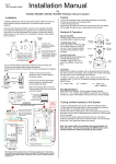
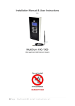
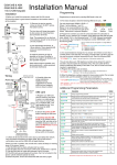
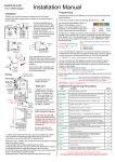
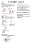
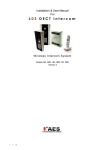
Installation Manual Ver 3 1200 keypad model for 603AB, 603ABK, 603HB, 603HBK Wireless Intercom System Testing Installation 1) Before installing fully, test the range of the system. Wire the unit as per wiring diagram, place the equipment in the desired location and test operation. 2) Ensure that the gate transmitter / receiver unit is installed to facilitate line of sight with the property or reception area. To achieve best results, mount the unit as high as possible from the ground. Should you need to extend range, you can mount it on a small pole to elevate it a few meters from the ground. House or reception area 150m Typical Entrance Pillar For longer range applications, locate the handset near a window at front of property. Note: Wood and glass only reduce signal strength by 10-20%. Masonry will reduce signal strength by 20-50% per wall. Metal can totally block signals. Transmitter / receiver - Keep away from ground, as high as possible. For best results, do not install too close to sources of electrical interference e.g. gate automation panel Speech Unit 3) It is recommended to charge the handset for 7-8 hours before use. 4) Power up the handset after inserting the batteries. 5) Wire the door station and transmitter / receiver according to the diagram below.. 3) Remove the top two security screws as shown. Do NOT remove the bottom screws. Call Button The front door will hinge downwards to allow access for mounting holes and connection terminals. Optional keypad module ARCHITECTURAL MODEL HOODED MODEL Note: The protective film on the front of the intercom should not be removed until fully installed. Mount AB model to wall with Never drill holes in 10mm x 50mm the top of the large wall enclosure. Cable anchors to entry should be prevent removal through the bottom. or theft. 8 meters max Screened CAT 5 Intercom Note: For improved audio performance, the shield wire can be connected to bolts on metal housing of speech panel. MIC connections OUT3 N/O COM N/C + - ADJUST VOLUME Press or to adjust volume level, and press MENU to select and save. CHANGE RING TONE Press and the unit will ring under the currently select tone. Press and to cycle through available ring tones. Press MENU to select and save. CHANGE LANGUAGE Press and the unit will display the currently selected language. 1=English. Press and to cycle. Press MENU to select and save. Reception indicator Battery Level 12.21 Voicemail Symbol Vibration ON/OFF ON/OFF MENU Charging base Code Button Power LED VOICEMAIL When the door station is pressed, and not answered within 40 seconds, the visitor can leave a message. Once complete, the handset will display the symbol. Up to 16 messages can be saved. To listen to voicemail, press MENU to play. If there are more than 1 message, press and to select the message required and press MENU to play. = Pause / Exit = Continue = Delete, long press = delete all. SET TIME ON DISPLAY Press MENU for 2 seconds. The hour digits will begin flashing. Press or to adjust. Press MENU to cycle from hour setting to minutes and repeat. Press MENU a third time to exit and save changes. 602 Range Foil screening wrapped around MIC wires for best performance! + GND Solid shield wire Code button Tamper N/C Handset & Operation Transmitter (keep short for better audio) 12v dc + - + - 1) Check all connections are correct before switching on the power. 2) Press the call button on the speech panel. 3) The handset should ring. 4) Press the button to answer the call and check two way speech. 5) Press to check the door / gate release function works. INT Lock Coding another handset to the System To add an extra handset to the system, follow the sequence below.. 1) Press and HOLD the code button on the door station for 3 seconds, until the LED’s on the bottom of the board start to flash. 2) Press and hold the Code button on the new handset ignoring the first short tone, until you hear a confirmation tone (“Di-Do-Do”). This may take up to 10 seconds. 3) Once the door station lights stop flashing, then you can test the system by pressing the call button on the door station. The new handset should ring. If not, repeat the process from the top. Note: For earlier models, the existing master handset lights will flash after step 1. You will need to press the MENU button on the existing handset first, before proceeding to step 2 above. O/P1 inhib Sense (-)GND DU out K or A N/C C N/O -+ 12v dc in egress N/O COM N/C N/O COM N/C Volt free Relay output (4 sec pulse) Shielded CAT5 cable 12-24v OUT1 OUT2 dc Keypad Connections (ABK model) Note: Keypad volt free output(s) needs connected to gate control panel or electric door lock as well as relay output from the intercom controller PCB. Parallel connect C and N/O contacts for electric gate controller or strike lock. Series connect C and N/C contacts for magnetic lock. Keypad Programming (only ABK models) Restoring defaults LED indicators While in programming mode, enter the following to delete all codes and settings apart from the Master code.. (this can take up to 2.5 minutes)... ON when incorrect codes entered and outputs are locked out. GREEN when output 1 activated. RED when output 2 activated. 9 1 2 3 FAST FLASHING – Wrong code entered / error. 4 5 6 SLOW FLASHING - in normal standby mode. 7 8 9 ON in programming mode. * 0 # ON when relay 3 activated. Enter Programming mode 0 0 0 * The unit is now in programming mode. Amber LED will remain ON. 0000 is default programmers code. Note: Pressing ** again will exit programming mode. * 9 9 # When the master code is forgotten…. 1) Wire a push button (or replicate with wire link) across the EG IN terminal and (-)GND. 2) Switch off power for 1 minute. 3) Switch ON power. 4) during the first 60 seconds, press the EG button once to enable the function. 5) Enter the following code.. Note: Programming can only begin 60 seconds after power on. 0 9 8 0 8 0 * * The keypad should now be in programming mode, ready to accept new data. Enter new programmers code 0 1 ? Location ? ? ? # 4-8 digit code Additional keypad information – Note: These features are not commonly used. Validate EG IN (EGRESS INPUT) Connect a push button between this terminal and (-)GND. When Egress button is pressed, output 1 will be activated for the programmed delay. Egress button is usually located inside a building and used as a push to exit. Record or Delete user codes 1 0 2 10= relay 1 codes (1000 available) 20= relay 2 codes (100 available) 30= relay 3 codes (100 available) 0 0 0 ? ? Memory locations 000-999 for relay 1 001-100 for relay 2 001-100 for relay 3 2= add code 5= delete code ? ? # Pin code 4-8 digits Validate 0 2 Group 2 0 Add code 3 1 5 Location 31 5 5 5 Pin code 5555 # Interlock Output NPN transistor output, open collector, max power 24v dc, 100mA sink. Used to operate a door in conjunction with another keypad, or prevent two doors being opened at the same time. ? 10=relay1 20=relay2 30=relay3 5 ? Delete code ? ? # ID location to be deleted Tamper N/C Normally closed tamper switch. This can be used in conjunction with a tamper switch on a box or enclosure to prevent tampering. This can be connected to an alarm system. Validate Delete all codes in a group ? ? 0 10=relay1 group 20=relay2 group 30=relay3 group 9 9 9 # Super delete code Validate Programming Relay output times & modes ? ? 0 1 or - 9 9 9 9 0 = start / stop toggle mode (latching) 1-99999 = seconds momentary operation 51=relay1 52=relay2 53=relay3 9 # Validate Programming SUPER user code Super user code is an optional feature which allows the same code to operate outputs 1, 2 or 3. 0 O/P 1 Inhibit Normally open. When closed, this disables all codes for relay group 1 except super user and duress codes. Validate Delete a code ? DU OUT (DURESS OUTPUT) An NPN transistor open collector output. It switches to (-) ground after the Duress Code is entered. Use it to trigger an alarm zone, or turn on a buzzer to notify a guard. Ic max: 100mA sink. Vc max: 24VDC DOOR SENSE N/C connected to (-)GND, to be connected to a normally closed door contact. It can be used to generate a door open alarm or door forced open alarm. Example: Add user 31 to have access code 5555 operating relay 2…. 2 K or A. (KEYPAD ACTIVE OUTPUT) An NPN transistor open collector output. It switches to (-) ground for 10 seconds on each key touching. This can be used to turn on lights, CCTV camera, or buzzer to notify a guard. The rating of this output is: Ic max: 100mA sink, Vc max: 24VDC 2 ? Location ? ? ? # 4-8 digit code Validate Using super user code ? ? ? ? # 1 Activate output 1 ? ? ? ? # 2 Activate output 2 ? ? ? ? # 3 Activate output 3 Using standard user code To use standard code, simply enter the 4 digit code. Note: Remember to exit programming mode with ** before testing user codes. SELF INSTALL - NEED TECHNICAL ASSISTANCE? OPTION 1: DIRECT WITH THE SERVICE DESK – QUICKEST AND MOST EFFECTIVE METHOD Submit your enquiry direct with the service desk at – [email protected] The service desk has the most experienced staff in Australia to help with your problem but they need your help. Describe your problem in detail and as clearly as possible. Don’t forget to include a telephone number. Be certain to detail which model or models of you are working with. Send photos of the installation – they love photos. The people at the service desk are good but they are even better when they can see the installation. Send photos of the overall scene so they can see the entire installation. Also send photos of the wiring to the control board and any other part of the installation you think is relevant. Send video if appropriate. Smartphone’s these days take remarkably good video in small file sizes which can be emailed in a moment. If your problem needs a video to show the issue please feel free to send it. NOTE: THIS IS BY FAR THE FASTEST AND MOST SUCCESFUL WAY TO SOLVE YOUR PROBLEM PHOTOS AND VIDEOS ARE THE NEXT BEST THING TO BEING THERE OPTION 2: LODGE YOUR ENQUIRY LOCALLY - SLOWER BUT CAN STILL BE EFFECTIVE Make contact with the store of purchase. Branch staffs are typically not technicians and dependent on their length of service will have varying degrees of technical knowledge. If they cannot help however they will certainly either source help locally from their technicians or make contact with the service technicians on your behalf. OPTION 3: SERVICE CALL WITH AUTOMATIC SOLUTIONS TECHNICIAN – SLOWEST METHOD If you fall within the local branch service area it may be possible to book a local technician to look at your installation. Wait times will vary dependent on local workloads. The cost is a service fee which includes the first half hour and the hourly rate thereafter. If any Automatic Solutions provided parts are found to be defective and within warranty these will be provided free of charge. (NOTE: If you suspect that any parts are defective and within warranty you may wish to consider option 4) A note on this option: If you decide on this option you will be asked to sign an “authorisation to proceed” which will provide legal authority and payment security. This form has three options available of which only the first two are available to you. The third option is for warranty repairs only for full install customers. Self install customers requiring warranty only service need to refer to option four below. IMPORTANT: IN SHORT THIS OPTION WILL INCUR CHARGES OPTION 4: RETURN THE PRODUCT IF BELIEVED TO BE FAULTY As a self install customer who has purchased product if you believe the product to be faulty rather than an installation or site problem you have the option of returning the product for evaluation and to exercise your right to a replacement, repair or refund as applicable. All returned product is forwarded immediately to the service technicians for evaluation and response. There are two main methods available to return product – Direct to the service centre – this is the quickest method as it cuts out the branch delay Via the branch of purchase – slower because of the delay at the branch When choosing this option you need to complete a product return form. This form gives you all the information on procedure involved and where to send to. These are available at the branch of purchase, can be emailed to you (contact your branch), or available here - http://automaticsolutions.com.au/page/warranty.php