1
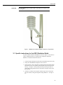
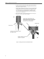
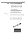
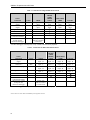
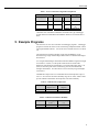
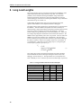
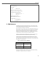
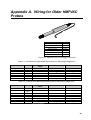
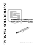
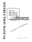
HMP45C
Temperature and
Relative Humidity Probe
User Guide
Issued 27.5.09
Copyright © 1990-2009 Campbell Scientific Inc.
Printed under Licence by Campbell Scientific Ltd.
CSL 373
Guarantee
This equipment is guaranteed against defects in materials and
workmanship. This guarantee applies for twelve months from date of
delivery. We will repair or replace products which prove to be defective
during the guarantee period provided they are returned to us prepaid. The
guarantee will not apply to:
•
Equipment which has been modified or altered in any way without the
written permission of Campbell Scientific
•
Batteries
•
Any product which has been subjected to misuse, neglect, acts of God
or damage in transit.
Campbell Scientific will return guaranteed equipment by surface carrier
prepaid. Campbell Scientific will not reimburse the claimant for costs
incurred in removing and/or reinstalling equipment. This guarantee and the
Company’s obligation thereunder is in lieu of all other guarantees,
expressed or implied, including those of suitability and fitness for a
particular purpose. Campbell Scientific is not liable for consequential
damage.
Please inform us before returning equipment and obtain a Repair
Reference Number whether the repair is under guarantee or not. Please
state the faults as clearly as possible, and if the product is out of the
guarantee period it should be accompanied by a purchase order.
Quotations for repairs can be given on request.
When returning equipment, the Repair Reference Number must be clearly
marked on the outside of the package.
Note that goods sent air freight are subject to Customs clearance fees
which Campbell Scientific will charge to customers. In many cases, these
charges are greater than the cost of the repair.
Campbell Scientific Ltd,
Campbell Park, 80 Hathern Road,
Shepshed, Loughborough, LE12 9GX, UK
Tel: +44 (0) 1509 601141
Fax: +44 (0) 1509 601091
Email: [email protected]
www.campbellsci.co.uk
PLEASE READ FIRST
About this manual
Please note that this manual was originally produced by Campbell Scientific Inc. primarily for the
North American market. Some spellings, weights and measures may reflect this origin.
Some useful conversion factors:
Area:
Length:
1 in2 (square inch) = 645 mm2
1 in. (inch) = 25.4 mm
1 ft (foot) = 304.8 mm
1 yard = 0.914 m
1 mile = 1.609 km
Mass:
1 oz. (ounce) = 28.35 g
1 lb (pound weight) = 0.454 kg
Pressure:
1 psi (lb/in2) = 68.95 mb
Volume:
1 UK pint = 568.3 ml
1 UK gallon = 4.546 litres
1 US gallon = 3.785 litres
In addition, while most of the information in the manual is correct for all countries, certain information
is specific to the North American market and so may not be applicable to European users.
Differences include the U.S standard external power supply details where some information (for
example the AC transformer input voltage) will not be applicable for British/European use. Please
note, however, that when a power supply adapter is ordered it will be suitable for use in your country.
Some brackets, shields and enclosure options, including wiring, are not sold as standard items in the
European market; in some cases alternatives are offered. Details of the alternatives will be covered in
separate manuals.
Recycling information
At the end of this product’s life it should not be put in commercial or domestic refuse
but sent for recycling. Any batteries contained within the product or used during the
products life should be removed from the product and also be sent to an appropriate
recycling facility.
Campbell Scientific Ltd can advise on the recycling of the equipment and in some cases
arrange collection and the correct disposal of it, although charges may apply for some
items or territories.
For further advice or support, please contact Campbell Scientific Ltd, or your local agent.
Campbell Scientific Ltd, Campbell Park, 80 Hathern Road, Shepshed, Loughborough, LE12 9GX, UK
Tel: +44 (0) 1509 601141 Fax: +44 (0) 1509 601091
Email: [email protected]
www.campbellsci.co.uk
Contents
PDF viewers note: These page numbers refer to the printed version of this document. Use
the Adobe Acrobat® bookmarks tab for links to specific sections.
1. General Description .................................................... 1
2. Specifications .............................................................. 1
2.1 Temperature Sensor ..................................................................................2
2.2 Relative Humidity Sensor.........................................................................2
3. Installation.................................................................... 2
3.1 Specific instructions for the URS1 Radiation Shield................................3
4. Wiring ........................................................................... 5
5. Example Programs ...................................................... 7
6. Long Lead Lengths ................................................... 10
7. Absolute Humidity..................................................... 12
8. Maintenance............................................................... 15
9. References ................................................................. 16
Appendix
A. Wiring for Older HMP45C Probes .......................... A-1
Figures
1. HMP45C and 41003-5 Radiation Shield on a Tripod Mast........................3
2. Inserting the Probe into the Radiation Shield .............................................4
3. HMP45C Probe to Datalogger Connections...............................................5
A-1. HMP45C Probe to Datalogger Connections...................................... A-1
i
Tables
1. Connections for Single-Ended Measurements............................................6
2. Connections for Differential Measurements...............................................6
3. Power Connections using PSW12 Peripherals ...........................................7
4. Calibration for Temperature .......................................................................7
5. Calibration for Relative Humidity ..............................................................7
6. Wiring for Single-ended Measurement Examples......................................8
7. Wiring for Differential Measurement Examples ......................................10
8. Wiring for Vapour Pressure Examples.....................................................13
9. Chemical Tolerances of HMP45C............................................................16
A-1. Connections for Single-Ended Measurements for Old Wiring
Configuration.................................................................................A-1
A-2. Connections for Differential Measurements for Old Wiring
Configurations ...............................................................................A-1
ii
HMP45C Temperature and Relative
Humidity Probe
1. General Description
The HMP45C Temperature and Relative Humidity probe contains a Platinum
Resistance Temperature detector (PRT) and a Vaisala HUMICAP® 180
capacitive relative humidity sensor.
The HMP45C can be powered continuously or the power may be switched to
conserve battery life. The HMP45C consumes less than 4 milliamperes current
at 12 volts. Approximately 0.15 seconds is required for the sensor to warm up
after power is switched on. At measurement rates slower than once per second,
the overall power consumption (datalogger and sensors) may be reduced by
switching power to the HMP45C. Most current Campbell Scientific dataloggers
have a built-in switched 12 volts that can be used to control power.
The CR9000, CR510, CR500, CR7, CR10 and 21X dataloggers do not have a
built-in switched 12 volts. Users with these dataloggers can power the sensor
continuously or purchase the model PSW12 to switch power.
2. Specifications
Operating Temperature: -40°C to +60°C
Storage Temperature: -40°C to +80°C
Probe Length: 25.4 cm (10 in.)
Probe Body Diameter: 2.5 cm (1 in.)
Filter: 0.2 μm Teflon membrane
Filter Diameter: 1.9 cm (0.75 in.)
Power Consumption: <4 mA @ 12 V
Supply Voltage: 7 to 35 VDC
Settling Time: 0.15 seconds
The HMP45C ships with:
(1) Adjustment Screwdriver from mfg
(1) Calibration Sheet
(1) Instruction Manual
1
HMP45C Temperature and RH Probe
2.1 Temperature Sensor
Sensor: 1000 Ω PRT, IEC 751 1/3 Class B
Temperature Measurement Range: -40°C to +60°C
Temperature Output Signal range: 0.008 to 1.0 V
Temperature Accuracy:
Error ( o C)
0.4
0.2
0.0
-0.2
-0.4
-40
-20
0
20
40
60
o
Temperature ( C)
2.2 Relative Humidity Sensor
Sensor: HUMICAP® 180
Relative Humidity Measurement Range: 0 to 100% non-condensing
RH Output Signal Range: 0.008 to 1 VDC
Accuracy at 20°C
±2% RH (0 to 90% Relative Humidity)
±3% RH (90 to 100% Relative Humidity)
Temperature Dependence of Relative Humidity Measurement: ±0.05% RH/°C
Typical Long Term Stability: Better than 1% RH per year
Response Time (at 20°C, 90% response): 15 seconds with membrane filter
3. Installation
The HMP45C must be housed inside a radiation shield when used in the field.
The MET21, URS1 (Figure 1) or 41003-5 Radiation Shield (Figure 1 and 2)
mounts to a tripod mast, UT930 ATW tower leg.
A standard lead length of 3 m allows the HMP45C to be mounted at a 2 or 3 m
height on a tripod mast or tower leg.
NOTE
The black outer jacket of the cable is Santoprene® rubber. This
compound was chosen for its resistance to temperature extremes,
moisture, and UV degradation. However, this jacket will support
combustion in air. It is rated as slow burning when tested
according to U.L. 94 H.B. and will pass FMVSS302. Local fire
codes may preclude its use inside buildings.
With the exception of the URS1 (see below) the probe should be installed so the
tip of the probe is positioned in the middle of the shield, relative to top and
bottom plates of the shield.
2
User Guide
CAUTION
Do not overtighten the nut that holds in the probe as the probe could
be damaged.
Figure 1. HMP45C and 41003-5 Radiation Shield on a Tripod Mast
3.1 Specific instructions for the URS1 Radiation Shield
A typical radiation shield for the HMP45C is shown in Figure 1. This shield, as
sold by Campbell Scientific, is supplied with an adapter that enables the
HMP45C to be fitted and detached as follows:
1. Loosen the large retaining nut at the bottom of the shield until it turns freely.
2. Gently insert the HMP45C through the centre of the nut.
3. During insertion, observe the probe by looking through the radiation shield
between the lowest curved plate and the flat white disc at the bottom of the
housing – see Figure 2. The tip of the probe will pass through a hole in a
white rubber sealing membrane that is mounted on the upper surface of the
flat white disc.
4. Continue to carefully insert the probe until the larger section of the probe
body (the ‘handle’) emerges through the sealing membrane – see Figure 2
(a).
3
HMP45C Temperature and RH Probe
5. Continue to carefully insert the probe a further 10mm, until the shoulder of
the larger section is approximately level with the hole in the lowest curved
disc, as shown in Figure 2 (b), below.
6. Tighten the large retaining nut by hand (do not use any tools) until the probe
is firmly gripped. If the probe does not appear to be sitting squarely inside
the shield, loosen the nut, re-position the probe and re-tighten. DO NOT
PULL THE PROBE DOWNWARDS PRIOR TO TIGHTENING THE
NUT, as this will also pull the sealing membrane downwards producing a
water trap. (See CAUTION below.)
7. Finally, bend the cable in a gentle loop back up towards the mounting arm
and attach it to the arm with the cable ties supplied.
(a)
Larger section of probe body in final
position (level with lip of first curved disc)
and showing the sealing membrane on
the flat disc in the correct position.
Flat white disc.
Observe here
Carefully push the HMP45C up into
the radiation shield.
Sealing membrane must curve
upwards to repel water.
Figure 2 Inserting the Probe into the Radiation Shield
4
(b)
User Guide
CAUTION
1. Do not push the probe so far into the radiation shield
that the sensor tip touches the top of the shield.
2. Ensure that your last action before tightening the large
securing nut is not to withdraw the probe (i.e. do not pull
in a downwards direction). This will cause the sealing
membrane to also pull downwards and will form a well
around the sensor which may then trap water. The
sealing membrane must curve UPWARDS towards the
tip of the sensor to encourage any water to run away
from the sensor body – see Figure 2.
3. Do not over-tighten the nut, as it is possible to crush the
sensor if too much force is used.
4. Always use the cable ties provided to attach the cable to
the mounting arm to prevent cable movement in the
wind, which could cause the wire to break.
In dirty environments, clean the radiation shield every month.
4. Wiring
Connections to Campbell Scientific dataloggers are given in Tables 1 through 3.
The probe can be measured by two single-ended or differential analogue input
channels.
CAUTION
When measuring the HMP45C with single-ended
measurements, the blue and black leads must both be
connected to AG on the CR10(X) and CR500/CR510 or to
on the CR800/850, CR1000, CR5000, and CR23X.
Doing otherwise will connect the datalogger’s analogue and
power ground planes to each other, which in some cases
can cause offsets on low-level analogue measurements. To
avoid 4 mA flowing into analogue ground, switch the sensor
on/off for its own measurement.
Description
Temperature Signal
Relative Humidity Signal
Signal Reference
Power
Power Ground
Screen/Shield
Colour
White
Green
Blue
Red
Black
Shield
NOTE: These wire colours differ from HMP45C probes supplied in the USA.
Figure 3. HMP45C Probe to Datalogger Connections
5
HMP45C Temperature and RH Probe
Table 1. Connections for Single-Ended Measurements
Sensor
Connection
Temperature
Signal
Relative Humidity
Signal
Signal Reference
Power Ground
Shield
Power
Continuous/Switched
CR10X Power Control
if using SW12V
channel on datalogger
Colour
White
CR10X
Single-Ended
Input
Single-Ended
Input
AG
AG
G
SW12V
Green
Blue
Black
Shield
Red
CR1000,
CR3000,
CR800,
CR5000,
CR23X
Single-Ended
Input
Single-Ended
Input
SW12
CR10, CR510,
CR500
Single-Ended
Input
Single-Ended
Input
AG
AG
G
12V/PSW12*
21X, CR7
Single-Ended
Input
Single-Ended
Input
12V/PSW12*
Jumper from
SW12V Control to
Control Port
*On these dataloggers switched power is only available with the PSW12 peripheral.
Table 2. Connections for Differential Measurements
Sensor
Connection
Temperature
Signal
Temperature Signal
Reference
Relative Humidity Signal
Jumper to
Blue
Green
Signal Reference
Blue
Power Ground
Shield
Power
Continuous/Switched
CR10X Power Control
if using SW12V
channel on datalogger
Black
Shield
Red
Colour
White
CR10X
Differential
Input – H
Differential
Input – L
Differential
Input – H
Differential
Input – L
G
G
12V/SW12V
CR1000,
CR3000,
CR800,
CR5000,
CR23X
Differential
Input – H
Differential
Input – L
Differential
Input – H
Differential
Input – L
G
12V/SW12
CR10, CR510,
CR500
Differential
Input – H
Differential
Input – L
Differential
Input – H
Differential
Input – L
G
G
12V/PSW12*
Jumper from
SW12V Control
to Control Port
*On these dataloggers switched power is only available with the PSW12 peripheral.
NOTE: These wire colours differ from HMP45C probes supplied in the USA.
6
21X, CR7
Differential
Input – H
Differential
Input – L
Differential
Input – H
Differential
Input – L
12V/PSW12*
User Guide
Table 3. Power Connections using PSW12 Peripherals
HMP45C
Description
Colour
PSW12 Peripheral
Terminal
Wire
Datalogger
Power
Red
12V
Red
12V
Power Ground
Black
G
Black*
See tables
1&2
Control Port
Yellow
*The black wire of the PSW12 should be connected to the type of datalogger
ground channel recommended for the HMP45C black wire as listed in Table 1
and 2.
5. Example Programs
This section is for users who write their own datalogger programs. A datalogger
program to measure this sensor can be created using Campbell Scientific’s Short
Cut Program Builder software. You do not need to read this section to use Short
Cut.
The temperature and relative humidity signals from the HMP45C can be
measured using a single-ended analogue measurement or a differential analogue
measurement.
Use a single-ended analogue measurement when the HMP45C signal lead length
is less than 6.1 m (20 ft.) or if the probe will be turned on and off under
datalogger control between measurements. For lead lengths greater than 6.1 m
(20 ft.) or when the probe will be continuously powered, use a differential
analogue measurement. For a discussion on errors caused by long lead lengths
see Section 6.
The HMP45C output scale is 0 to 1000 millivolts for the temperature range of
-40°C to +60°C and for the relative humidity range of 0 to 100%. Tables 4 and 5
provide calibration information for temperature and relative humidity.
Table 4. Calibration for Temperature
Units
Celsius
Fahrenheit
Multiplier
(degrees mV-1)
0.1
0.18
Offset
(degrees)
-40
-40
Table 5. Calibration for Relative Humidity
Units
Percent
Fraction
Multiplier
(% mV-1)
0.1
0.001
Offset
(%)
0
0
7
HMP45C Temperature and RH Probe
Table 6. Wiring for Single-ended
Measurement Examples
Description
Temperature
Relative Humidity
Signal Reference
Jumper from
SW12V Control
Power
Power Ground
Shield
Colour
White
Green
Blue
CR1000
SE 2 (1L)
SE 1 (1H)
N/A
Red
Black
Clear
SW12 V
CR10(X)
SE 3 (2H)
SE 4 (2L)
AG
C1
SW12 V
AG
G
NOTE: These wire colours differ from HMP45C probes supplied in the USA.
CR1000 Program using Single-Ended Measurement Instructions Using SW12 on Datalogger
'CR1000 program to measure HMP45C with single-ended measurements
Public AirTC
Public RH
DataTable(Temp_RH,True,-1)
DataInterval(0,60,Min,0)
Average(1,AirTC,IEEE4,0)
Sample(1,RH,IEEE4)
EndTable
BeginProg
Scan(1,Sec,1,0)
'HMP45C Temperature & Relative Humidity Sensor measurements AirTC and RH:
SW12 (1 )
Delay(0,150,mSec)
VoltSE(AirTC,1,mV2500,2,0,0,_50Hz,0.1,-40.0)
VoltSE(RH,1,mV2500,1,0,0,_50Hz,0.1,0)
SW12 (0)
If RH>100 And RH<108 Then RH=100
CallTable(Temp_RH)
NextScan
EndProg
8
User Guide
CR10(X) Program using Single-Ended Measurement Instructions Using a PSW12 or SW12V on
Datalogger
;Turn the HMP45C on.
;
01: Do (P86)
1: 41
Set Port 1 High
;Jumper wire from PSW12 control to C1
;Yellow wire (C1) if using PSW12 device
;For CR23X or CR5000 use 49 for SW12V internal
;control port
;Pause 150 mSec before making measurements so the
;probe can stabilize on true readings.
;
02: Excitation with Delay (P22)
1: 1
Ex Channel
2: 0
Delay W/Ex (units = 0.01 sec)
3: 15
Delay After Ex (units = 0.01 sec)
4: 0
mV Excitation
;Measure the HMP45C temperature.
;
03: Volt (SE) (P1)
1: 1
Reps
2: 5
2500 mV Slow Range
3:
4:
5:
6:
3
1
.1
-40
SE Channel
Loc [ T_C
Mult
Offset
]
;See Table 4 for alternative multipliers
;See Table 4 for alternative offsets
;Measure the HMP45C relative humidity.
;
04: Volt (SE) (P1)
1: 1
Reps
2: 5
2500 mV Slow Range
3:
4:
5:
6:
4
2
.1
0
;CR510, CR500 (2500mv); CR23X (1000 mV);
21X, CR7 (5000 mV)
SE Channel
Loc [ RH_pct
Mult
Offset
;CR510, CR500 (2500 mV); CR23X (1000 mV);
21X, CR7 (5000 mV)
]
;See Table 5 for alternative multipliers
;Turn the HMP45C off.
;
05: Do (P86)
1: 51
Set Port 1 Low
9
HMP45C Temperature and RH Probe
6. Long Lead Lengths
This section describes the error associated with measuring the HMP45C with a
single-ended measurement if the probe has a long cable. To avoid these
problems, CSI recommends measuring the HMP45C using a differential
analogue measurement (Instruction 2) when long lead lengths are required.
Generic datalogger connections for measuring the HMP45C using a differential
measurement are given in Table A-2.
Understanding the details in this section are not required for the general
operation of the HMP45C with Campbell Scientific’s dataloggers.
The signal reference (blue) and the power ground (black) are in common inside
the HMP45C. When the HMP45C temperature and relative humidity are
measured using a single-ended analogue measurement, both the signal reference
and power ground are connected to ground at the datalogger. The signal
reference and power ground both serve as the return path for 12 V. There will
be a voltage drop along those leads because the wire itself has resistance. The
HMP45C draws approximately 4 mA when it is powered. The wire used in the
HMP45C (P/N 9721) has resistance of 27.7 Ω/1000 feet. Since the signal
reference and the power ground are both connected to ground at the datalogger,
the effective resistance of those wires together is half of 27.7 Ω/1000 feet, or
13.9 Ω/1000 feet. Using Ohm’s law, the voltage drop (Vd), along the signal
reference/power ground, is given by Eq. (1).
Vd
= I ∗R
= 4 mA ∗ 13.9 Ω 1000 ft
(1)
= 55.6 mV 1000 ft
This voltage drop will raise the apparent temperature and relative humidity
because the difference between the signal and signal reference lead, at the
datalogger, has increased by Vd. The approximate error in temperature and
relative humidity is 0.56°C and 0.56% per 100 feet of cable length, respectively.
Table 7. Wiring for Differential Measurement Examples
Description
Temperature
Jumper to 1L
Relative Humidity
Signal Reference
Jumper from SW12V Control
Power
Power Ground
Shield
Colour
White
Green
Blue
Red
Black
Clear
CR10(X)
2H
2L
1H
1L
C1
SW12 V
G
G
CR1000
2H
2L
1H
1L
N/A
SW12 V
G
NOTE: These wire colours differ from HMP45C probes supplied in the USA.
10
User Guide
CR1000 Program using Differential Measurement Instructions Using SW12 on Datalogger
'CR1000 program to measure HMP45C with differential measurements
Public AirTC
Public RH
DataTable(Temp_RH,True,-1)
DataInterval(0,60,Min,0)
Average(1,AirTC,IEEE4,0)
Sample(1,RH,IEEE4)
EndTable
BeginProg
Scan(1,Sec,1,0)
'HMP45C Temperature & Relative Humidity Sensor measurements AirTC and RH:
SW12 (1 )
Delay(0,150,mSec)
VoltDiff (AirTC,1,mV2500,2,True,0,_50Hz,0.1,-40)
VoltDiff (RH,1,mV2500,1,True,0,_50Hz,0.1,0)
SW12 (0)
If RH>100 And RH<108 Then RH=100
CallTable(Temp_RH)
NextScan
EndProg
CR10(X) Program using Differential Measurement Instructions Using SW12V on Datalogger
;Turn the HMP45C on.
;
01: Do (P86)
1: 41
Set Port 1 High
;Jumper wire from SW12V control to C1
;Yellow wire (C1) if using PSW12 device
;For CR23X or CR5000 use 49 for SW12V internal
;control port
;Pause 150 mSec before making measurements so the
;probe can stabilize on true readings.
;
02: Excitation with Delay (P22)
1: 1
Ex Channel
2: 0
Delay W/Ex (units = 0.01 sec)
3: 15
Delay After Ex (units = 0.01 sec)
4: 0
mV Excitation
11
HMP45C Temperature and RH Probe
;Measure the HMP45C temperature.
;
03: Volt (Diff) (P2)
1: 1
Reps
2: 5
2500 mV Slow Range
3:
4:
5:
6:
2
1
.1
-40
DIFF Channel
Loc [ T_C
]
Mult
Offset
;Measure the HMP45C relative humidity.
;
04: Volt (Diff) (P2)
1: 1
Reps
2: 5
2500 mV Slow Range
3:
4:
5:
6:
1
2
.1
0
DIFF Channel
Loc [ RH_pct ]
Mult
Offset
;CR510, CR500 (2500mv); CR23X (1000 mV);
21X, CR7 (5000 mV)
;See Table 4 for alternative multipliers
;See Table 4 for alternative offsets
;CR510, CR500 (2500mv); CR23X (1000 mV);
21X, CR7 (5000 mV)
;See Table 5 for alternative multipliers
;Turn the HMP45C off.
;
05: Do (P86)
1: 51
Set Port 1 Low
7. Absolute Humidity
The HMP45C measures the relative humidity. Relative humidity is defined by
the equation below:
RH =
e
∗ 100
es
(2)
where RH is the relative humidity, e is the vapour pressure in kPa , and es is the
saturation vapour pressure in kPa. The vapour pressure, e, is an absolute
measure of the amount of water vapour in the air and is related to the dew point
temperature. The saturation vapour pressure is the maximum amount of water
vapour that air can hold at a given air temperature. The relationship between
dew point and vapour pressure, and air temperature and saturation vapour
pressure are given by Goff and Gratch (1946), Lowe (1977), and Weiss (1977).
When the air temperature increases, so does the saturation vapour pressure.
Conversely, a decrease in air temperature causes a corresponding decrease in
saturation vapour pressure. It follows then from Eq. (2) that a change in air
temperature will change the relative humidity, without causing a change in
absolute humidity.
For example, for an air temperature of 20°C and a vapour pressure of 1.17 kPa,
the saturation vapour pressure is 2.34 kPa and the relative humidity is 50%. If
the air temperature is increased by 5°C and no moisture is added or removed
from the air, the saturation vapour pressure increases to 3.17 kPa and the relative
humidity decreases to 36.9%. After the increase in air temperature, there is
more energy to vaporise the water. However, the actual amount of water vapour
12
User Guide
in the air has not changed. Thus, the amount of water vapour in the air, relative
to saturation, has decreased.
Because of the inverse relationship between relative humidity and air
temperature, finding the mean relative humidity is meaningless. A more useful
quantity is the mean vapour pressure. The mean vapour pressure can be
computed on-line by the datalogger (Example 3).
Table 8. Wiring for Vapour Pressure Examples
Description
Temperature
Relative Humidity
Signal Reference
Jumper from
SW12V Control
Power
Power Ground
Shield
Colour
White
Green
Blue
CR1000
SE 2 (1L)
SE 1 (1H)
N/A
Red
Black
Clear
SW12 V
CR10(X)
SE 3 (2H)
SE 4 (2L)
AG
C1
SW12 V
AG
G
NOTE: These wire colours differ from HMP45C probes supplied in the USA.
CR1000 Program that Computes Vapour Pressure and Saturation Vapour Pressure
'CR1000 program that calculates Vapour Pressure
Public AirTC
Public RH
Public RH_Frac, e_Sat, e_kPa
DataTable(Temp_RH,True,-1)
DataInterval(0,60,Min,0)
Average(1,AirTC,IEEE4,0)
Sample(1,RH,IEEE4)
Sample(1,e_kPa,IEEE4)
EndTable
BeginProg
Scan(1,Sec,1,0)
'HMP45C Temperature & Relative Humidity Sensor measurements AirTC and RH:
SW12 (1 )
Delay(0,150,mSec)
VoltSE(AirTC,1,mV2500,2,0,0,_50Hz,0.1,-40.0)
VoltSE(RH,1,mV2500,1,0,0,_50Hz,0.1,0)
SW12 (0)
If RH>100 And RH<108 Then RH=100
'Calculate Vapour Pressure
'Convert RH percent to RH Fraction
RH_Frac = RH * 0.01
'Calculate Saturation Vapour Pressure
SatVP(e_Sat, AirTC)
'Compute Vapour Pressure, RH must be a fraction
e_kPa = e_Sat * RH_Frac
CallTable(Temp_RH)
NextScan
EndProg
13
HMP45C Temperature and RH Probe
CR10(X) Program that Computes Vapour Pressure and Saturation Vapour Pressure
;Turn the HMP45C on.
;
01: Do (P86)
1: 41
Set Port 1 High
;Jumper wire from SW12V control to C1
;Yellow wire (C1) if using PSW12 device
;For CR23X or CR5000 use 49 for SW12V internal
;control port
;Pause 150 mSec before making measurements so the
;probe can stabilize on true readings.
;
02: Excitation with Delay (P22)
1: 1
Ex Channel
2: 0
Delay W/Ex (units = 0.01 sec)
3: 15
Delay After Ex (units = 0.01 sec)
4: 0
mV Excitation
;Measure the HMP45C temperature.
;
03: Volt (SE) (P1)
1: 1
Reps
2: 5
2500 mV Slow Range
3:
4:
5:
6:
3
1
.1
-40
SE Channel
Loc [ T_C
Mult
Offset
]
;Measure the HMP45C relative humidity.
;
04: Volt (SE) (P1)
1: 1
Reps
2: 5
2500 mV Slow Range
3:
4:
5:
6:
14
4
2
.001
0
;CR510, CR500 (2500mv); CR23X (1000 mV);
21X, CR7 (5000 mV)
SE Channel
Loc [ RH_frac ]
Mult
Offset
;CR510, CR500 (2500mv); CR23X (1000 mV);
21X, CR7 (5000 mV)
User Guide
;Turn the HMP45C off.
;
05: Do (P86)
1: 51
Set Port 1 Low
;Compute the saturation vapour pressure.
;The temperature must be in degrees Celsius.
;
06: Saturation Vapour Pressure (P56)
1: 1
Temperature Loc [ T_C
2: 3
Loc [ e_sat ]
]
;Compute the vapour pressure.
;Relative humidity must be a fraction.
;
07: Z=X*Y (P36)
1:
3 X Loc [ e_sat ]
2:
2 Y Loc [ RH_frac ]
3:
4 Z Loc [ e
]
8. Maintenance
The HMP45C Probe requires minimal maintenance. Check monthly to make
sure the radiation shield is free from debris. The black screen at the end of the
sensor should also be checked for contaminates.
When installed in close proximity to the ocean or other bodies of salt water (e.g.,
Great Salt Lake), a coating of salt (mostly NaCl) may build up on the radiation
shield, sensor, filter and even the chip. NaCl has an affinity for water. The
humidity over a saturated NaCl solution is 75%. A buildup of salt on the filter
or chip will delay or destroy the response to atmospheric humidity.
The filter can be rinsed gently in distilled water. If necessary, the chip can be
removed and rinsed as well. Do not scratch the chip while cleaning.
Long term exposure of the HUMICAP® relative humidity sensor to certain
chemicals and gases may affect the characteristics of the sensor and shorten its
life. Table 9 lists the maximum ambient concentrations, of some chemicals, that
the HUMICAP® can be exposed to.
Table 9. Chemical Tolerances of HMP45C
Chemical
Organic solvents
Aggressive chemicals
(e.g. SO2, H2SO4, H2S,
HCl, Cl2, etc.)
Weak Acids
Bases
Concentration (PPM)
1000 to 10,000
1 to 10
100 to 1000
10,000 to 100,000
Recalibrate the HMP45C annually. Obtain a returns number before returning
the HMP45C to Campbell Scientific for recalibration.
15
HMP45C Temperature and RH Probe
9. Troubleshooting
Symptom: -9999, NAN, -40 deg C, or 0% relative humidity
1.
Check that the sensor is wired to the correct excitation and analogue input
channels as specified by the measurement instructions.
2.
Verify the Range code is correct for the datalogger type.
3.
Verify the red power wire is correctly wired to the 12V, Switched 12V, or
PSW12 module. The terminal the wire is connected to will depend on the
datalogger program.
Connect the red wire to a 12V terminal to constantly power the sensor for
troubleshooting purposes. With the red wire connected to 12V, a
voltmeter can be used to check the output voltage for temperature and
relative humidity on the yellow and blue wires respectively (temperature
°C = mV *0.1 – 40.0; relative humidity % = mV * 0.1).
Symptom: Incorrect temperature or relative humidity.
1.
Verify the multiplier and offset parameters are correct for the desired units
(Table 5-1).
10. References
Goff, J. A. and S. Gratch, 1946: Low-pressure properties of water from -160° to
212°F, Trans. Amer. Soc. Heat. Vent. Eng., 51, 125-164.
Lowe, P. R., 1977: An approximating polynomial for the computation of
saturation vapour pressure, J. Appl. Meteor., 16, 100-103.
Weiss, A., 1977: Algorithms for the calculation of moist air properties on a
hand calculator, Amer. Soc. Ag. Eng., 20, 1133-1136.
16
Appendix A. Wiring for Older HMP45C
Probes
Description
Temperature Signal
Relative Humidity Signal
Signal Reference
Power Control
Power
Power Ground
Shield
Colour
Yellow
Blue
Purple
Orange
Red
Black
Shield
Figure A-1. HMP45C Probe to Datalogger Connections
Table A-1. Connections for Single-Ended Measurements for Old Wiring Configuration
Description
Colour
Temperature
Relative Humidity
Signal Reference
Power Control
Power
Power Ground
Shield
Yellow
Blue
Purple
Orange
Red
Black
Clear
CR10(X), CR510,
CR500
Single-Ended Input
Single-Ended Input
AG
Control Port
12 V
G
G
CR23X, CR5000
21X, CR7
Single-Ended Input
Single-Ended Input
Single-Ended Input
Single-Ended Input
Control Port
12 V
G
Control Port
12 V
Table A-2. Connections for Differential Measurements for Old Wiring Configurations
Description
Colour
Temperature
Signal Reference
Yellow
Jumper to
Purple
Blue
Purple
Orange
Red
Black
Clear
Relative Humidity
Signal Reference
Power Control
Power
Power Ground
Shield
CR10(X), CR510,
CR500
Differential Input (H)
Differential Input (L)
Differential Input (H)
Differential Input (L)
Control Port
12 V
G
G
This is a blank page.
CR23X, CR5000
21X, CR7
Differential Input (H)
Differential Input (L)
Differential Input (H)
Differential Input (L)
Differential Input (H)
Differential Input (L)
Control Port
12 V
G
Differential Input (H)
Differential Input (L)
Control Port
12 V
A-1
CAMPBELL SCIENTIFIC COMPANIES
Campbell Scientific, Inc. (CSI)
815 West 1800 North
Logan, Utah 84321
UNITED STATES
www.campbellsci.com
[email protected]
Campbell Scientific Africa Pty. Ltd. (CSAf)
PO Box 2450
Somerset West 7129
SOUTH AFRICA
www.csafrica.co.za
[email protected]
Campbell Scientific Australia Pty. Ltd. (CSA)
PO Box 444
Thuringowa Central
QLD 4812 AUSTRALIA
www.campbellsci.com.au
[email protected]
Campbell Scientific do Brazil Ltda. (CSB)
Rua Luisa Crapsi Orsi, 15 Butantã
CEP: 005543-000 São Paulo SP BRAZIL
www.campbellsci.com.br
[email protected]
Campbell Scientific Canada Corp. (CSC)
11564 - 149th Street NW
Edmonton, Alberta T5M 1W7
CANADA
www.campbellsci.ca
[email protected]
Campbell Scientific Ltd. (CSL)
Campbell Park
80 Hathern Road
Shepshed, Loughborough LE12 9GX
UNITED KINGDOM
www.campbellsci.co.uk
[email protected]
Campbell Scientific Ltd. (France)
Miniparc du Verger - Bat. H
1, rue de Terre Neuve - Les Ulis
91967 COURTABOEUF CEDEX
FRANCE
www.campbellsci.fr
[email protected]
Campbell Scientific Spain, S. L.
Psg. Font 14, local 8
08013 Barcelona
SPAIN
www.campbellsci.es
[email protected]
Campbell Scientific Ltd. (Germany)
Fahrenheitstrasse13, D-28359 Bremen
GERMANY
www.campbellsci.de
[email protected]
Please visit www.campbellsci.com to obtain contact information for your local US or International representative.