1
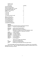
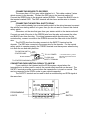
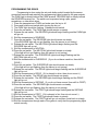
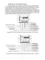
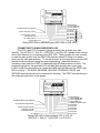
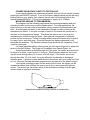
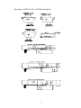
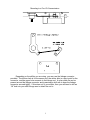
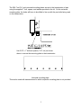
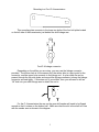
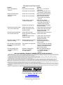
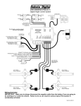
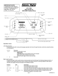
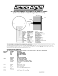
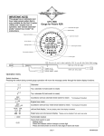
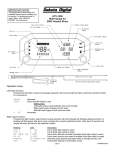
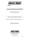
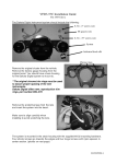
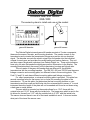
Universal Gear Shift Sender
GSS-1000
The easiest system to install and use on the market.
gear shift decoder.
GND
Dim
PWR
B.U.
N.S.
relay
Safety
Backup
Power
Dim
Park
Reverse
Neutral
Overdrv
Drive
Second
First
HI
Signal
Ground
GSS-1000
DECODER
gear shift sensor.
The Dakota Digital universal gear shift sender consists of 3 main components,
these are the sensor, decoder, and mounting brackets. The sender mounts to the
transmission and converts the transmission linkage arm position into an electrical
signal. The decoder converts the electric signal from the sender into the individual
outputs for each gear and provides the neutral safety and backup features. This unit
can also support single-wire indicators from Dakota Digital, Inc. These style indicators
have only one wire that sends the digital gear position information to the display. The
mounting brackets attach the sensor to the transmission housing and linkage arm.
The only parts of the gear shift sender that are different for the different
transmissions are the mounting brackets. The GM 350, 400, and 700-R4 use the same
linkage connector and mounting plate, but different holes in the mounting plate. The
Ford C-6 and C-4 each have different mounting plates and linkage connectors.
For other transmissions, a universal mounting plate is provided. This plate has
several mounting holes for the sensor, but no holes for mounting the plate to the
transmission. To use this plate, first determine the best mounting location on your
transmission and then mark and drill holes into the universal plate to secure it. In most
instances the entire length of the plate will not be needed and it can be cut down using
a hack saw or metal shears.
The arm which is mounted on the sender allows for a 1 3/4” throw with the
outside hole and 1 5/16” throw with the inside hole. The longer arm which is sent in the
kit allows for throws from 3 1/2” with the outside hole to 2 3/16” with the inside hole.
The sensor does not have to use all of the travel available to work. It does not matter
what part of the travel the sensor uses.
PARTS LIST
description
gear shift decoder
relay for neutral safety
gear shift sender with 10’ cable
long gear shift sender arm
spacer (7/16” hex nut)
5/16” x 1” bolt
5 1/4” rod
4 1/4” rod
3 1/4” rod
1/8” retainer clips for rods
GM mounting plate
GM linkage connector
C-4 mounting plate
C-4 linkage connector
C-6 mounting plate
C-6 linkage connector
universal mounting plate
quantity
1
1
1
1
2
2
1
1
1
6
1
1
1
1
1
1
1
WIRING
The terminals on the decoder are connected as follows:
SAFETY
Connect to neutral safety relay.
BACKUP
positive side of backup lights
POWER
Ignition terminal from fuse panel
DIM
Park light or tail light circuit (for LED indicators only)
*Connect to power for single-wire indicators
PARK
to park indicator
REVERSE to reverse indicator
NEUTRAL to neutral indicator
OVERDRV to overdrive indicator
DRIVE
to drive indicator
SECOND
to second indicator
FIRST
to first indicator
*data out for single-wire indicators
HI
red wire from gear sensor
SIGNAL
green wire from gear sensor
GND
chassis ground and black wire from gear sensor
The neutral safety and backup light features do not have to be connected for
gear sender to work. These are optional features provided for vehicles which do not
already have these provisions.
2
CONNECTING SENSOR TO DECODER
The sensor has a 10 foot gray cable attached to it. This cable contains 3 wires
which connect to the decoder. Connect the RED wire to the terminal marked HI.
Connect the GREEN wire to the terminal marked SIGNAL. Connect the BLACK wire to
the terminal marked GND. The GND terminal will also have another wire to chassis
ground.
CONNECTING THE NEUTRAL SAFETY RELAY
If your vehicle already has a neutral safety switch in the wiring harness to prevent
the vehicle from starting while it is in gear, then you do not need to connect this neutral
safety switch.
Otherwise, cut the wire that goes from your starter switch to the starter solenoid.
Connect one end of the wire to the GREEN wire from the relay and connect the other
end BLACK wire from the relay. For wiring harnesses which provide wires for the
neutral safety, connect one side to the GREEN wire and the other side to the BLACK
wire.
The WHITE wire from the relay connects to the SAFETY terminal on the
decoder. The RED wire connects to the power wire for the decoder. For the neutral
safety switch to operate properly, the POWER terminal must have power when the key
is in both the run and start positions.
TO IGNITION SWITCH
STARTER WIRE
do not connect
GREEN
(brown)
RED
BLUE
(orange)
WHITE
(black)
TO STARTER SOLENOID
BLACK
(yellow)
TO 12 V POWER
TO GSS-1000
SAFETY TERMINAL
* wire colors listed in ( ) are for
alternate relay sockets found in
some units.
CONNECTING PARK-NEUTRAL SIGNAL TO AN ECM
If your vehicle is fuel injected and the ECM requires a signal when the
transmission is in either park or neutral, the neutral safety terminal can be used. The
SAFETY terminal provides a ground when the transmission is in park or neutral. This
can be connected to the ECM in order to pass vehicle inspection.
The SAFETY terminal can be used for both a neutral safety and ECM signal at
the same time.
GND
Dim
PWR
B.U.
PROGRAMMING
LIGHTS
N.S.
relay
Safety
Backup
Power
Dim
Park
Reverse
Neutral
Overdrv
Drive
Second
First
HI
Signal
Ground
GSS-1000
DECODER
3
SET
SWITCH
PROGRAMMING THE GEARS
Programming is done using the set push-button switch located by the sensor
connection terminals and watching the programming lights located by the gear outputs.
The PARK light is directly behind the PARK terminal, REVERSE light is directly behind
the REVERSE terminal, etc. The switch can be pressed using a pen, pencil,
screwdriver, or other blunt object.
1. Place the transmission in PARK and make sure the key is off.
2. Press and hold the set switch while turning the key on.
3. The PARK light should be flashing. Release the set switch.
4. Press the set switch. The PARK light should remain on steady.
5. Release the set switch. The REVESE light should begin flashing and the PARK light
will go out.
6. Shift the transmission to REVERSE.
7. Press the set switch. The REVERSE light should remain on steady.
(If the REVERSE light will not quit flashing, then the sensor is not turning.)
8. Release the set switch. The NEUTRAL light should begin flashing and the
REVERSE light will go out.
9. Shift the transmission to NEUTRAL.
10. Press the set switch. The NEUTRAL light should remain on steady.
(If the light will not quit flashing, then the sensor is not turning.)
11. Release the set switch. The OVERDRIVE light should begin flashing and the
NEUTRAL light will go out.
12. Shift the transmission to OVERDRIVE. (If you do not have overdrive, then shift to
DRIVE.)
13. Press the set switch. The OVERDRIVE light should remain on steady.
(If the light will not quit flashing, then the sensor is not turning.)
14. Release the set switch. The DRIVE light should begin flashing and the OVERDRIVE
light will go out.
15. Shift the transmission to DRIVE. (If it is already in drive, then do not move it.)
16. Press the set switch. The DRIVE light should remain on steady.
17. Release the set switch. The SECOND light should begin flashing and the DRIVE
light will go out.
18. Shift the transmission to SECOND. (If you do not have second, then shift to FIRST.)
19. Press the set switch. The SECOND light should remain on steady.
(If the light will not quit flashing, then the sensor is not turning.)
20. Release the set switch. The FIRST light should begin flashing and the SECOND
light will go out.
21. Shift the transmission to FIRST. (If it is already in first, then do not move it.)
22. Press the set switch. The FIRST light should remain on steady.
23. Release the set switch. The FIRST light will go out and then come back on steady.
24. Shift the transmission through each of the gears to verify that the programming lights
match correctly.
4
CONNECTING TO THE GEAR SHIFT DISPLAY
Gear shift displays are not included with the GSS-1000, but it will interface with
all of the standard display systems available. Each gear output will provide 12 volts at
up to 0.3 amperes. This is enough current capacity for any LED indicator or low power
incandescent bulbs. When individual lights are used for each gear, connect the
negative wire to ground and the positive wire to the appropriate gear output terminal on
the decoder. When using Dakota Digital’s Digital Gear Shift Indicator connect the wires
to the decoder according to the instructions provided with the indicator. The GSS-1000
will also work with any Dakota Digital vacuum florescent display system. Connect wire
jumpers between the decoder and the display system control box.
Safety
Backup
Power
Dim
Park
Reverse
Neutral
Overdrv
Drive
Second
First
HI
Signal
Ground
GSS-1000
DECODER
to Chassis Ground
to sensor BLACK wire
to sensor GREEN wire
to sensor RED wire
to control box FIRST terminal
to control box SECOND terminal
to control box DRIVE terminal
to control box OVERDRIVE terminal
to control box NEUTRAL terminal
To ECM Park-Neutral input (optional)
To neutral safety relay (optional)
To back-up lights (optional)
+12V with key in 'ON'
and 'START' positions
to control box REVERSE terminal
to control box PARK terminal
do not connect
Wiring GSS-1000 to Dakota Digital VFD instrumentation system (STR systems)
Safety
Backup
Power
Dim
Park
Reverse
Neutral
Overdrv
Drive
Second
First
HI
Signal
Ground
GSS-1000
DECODER
to Chassis Ground
to sensor BLACK wire
to sensor GREEN wire
to sensor RED wire
to indicator BROWN wire
to indicator BLUE wire
to indicator ORANGE wire
to indicator YELLOW wire
to indicator PURPLE wire
To ECM Park-Neutral input (optional)
To neutral safety relay (optional)
To back-up lights (optional)
+12V with key in 'ON'
and 'START' positions
to indicator GRAY wire
to indicator GREEN wire
to parking lights circuit (DGS-1 only)
Wiring GSS-1000 to Dakota Digital individual gear shift indicator (DGS-1 or DGS-2)
5
to Chassis Ground
to sensor BLACK wire
to sensor GREEN wire
to sensor RED wire
to '1' red wire
to '2' red wire
to 'D' red wire
to 'O' red wire
to 'N' red wire
To ECM Park-Neutral input (optional)
To neutral safety relay (optional)
To back-up lights (optional)
+12V with key in 'ON'
and 'START' positions
to 'R' red wire
to 'P' red wire
To parking lights circuit
all black wires
grounded
Safety
Backup
Power
Dim
Park
Reverse
Neutral
Overdrv
Drive
Second
First
HI
Signal
Ground
GSS-1000
DECODER
Wiring GSS-1000 to individual lights (GSS-1002 or GSS-1003)
CONNECTING TO SINGLE-WIRE DISPLAYS
The VFD-3 and VFD-3X series III gauge systems have a single gear input
terminal. The ODYR-01-1, SLX-01-1, ODYR-02-1, and SLX-02-1 gauges have a brown
wire in their harness for connecting to the GSS-1000. These gauges use only one wire
to read the gear position from the GSS-1000 decoder instead of using six or seven
wires (one for each gear position). To set the decoder up for single-wire mode the DIM
terminal must have power during the gear programming. When the decoder is
operating in this mode the FIRST programming light will always remain on dimly. The
programming light for the gear that it is in will also flash showing the current gear
position (when the gear selector is in park the PARK light will flash and the FIRST light
will be on dimly.) The PARK, REVERSE, NEUTRAL, OVRDRIVE, DRIVE, and
SECOND terminals should not be connected to anything. The FIRST terminal will go to
the single-wire gear input on the gauge.
Safety
Backup
Power
Dim
Park
Reverse
Neutral
Overdrv
Drive
Second
First
HI
Signal
Ground
GSS-1000
DECODER
to Chassis Ground
to sensor BLACK wire
to sensor GREEN wire
to sensor RED wire
to indicator gear position input
do not connect
do not connect
do not connect
do not connect
To ECM Park-Neutral input (optional)
To neutral safety relay (optional)
To back-up lights (optional)
+12V with key in 'ON'
and 'START' positions
do not connect
do not connect
To +12V power
Wiring GSS-1000 to Dakota Digital VFD-3, VFD-3X,
ODYR-01-1, SLX-01-1, ODYR-02-1, or SLX-02-1
6
CONNECTING BACKUP LIGHTS TO THE GSS-1000
If your vehicle already has a backup light switch, then you do not need to connect
anything to the BACKUP terminal. If you do not have a backup switch and will be using
backup lights on your vehicle, then connect the hot side of the backup lights to the
terminal marked BACKUP. This circuit is designed to supply up to 15 amps.
MOUNTING SENSOR TO TRANSMISSION.
The diagrams on the following pages show the mounting hardware used and
mounting location for the most common transmissions. For most applications, the
sensor mounts to the side of the transmission using a couple of the transmission pan
bolts. An metal plate will attach to the transmission linkage so that it rotates as the
transmission is shifted. A rod with a couple of bends in it connects the sensor arm to
the plate on the transmission linkage. This allows the sensor arm to move as the
transmission is shifted through the gears. Each gear will correspond to a different
position for the sensor arm. It does not matter exactly where the sensor arm is when it
is in park, first or any other gear. Once the Decoder has been programmed it will
remember the positions. The Decoder converts these positions into separate a 12 volt
output for each gear.
If a Kugel adjustable shifter is being used, you will need a Kugel nut to attach the
sensor to the shift linkage. The Kugel nut is available from Dakota Digital, Inc.
As the transmission is shifted through all of the gears, the sensor arm should not
hit either of its stops, or get ‘bound’ or ‘hung up’. When properly adjusted, the sensor
arm will move through about 1/2 or more of its full travel. If the sensor arm moves
through less than 1/3 of its travel, it may be difficult for the decoder to distinguish
between gears. It does not matter which direction the sensor arm turns going from Park
to Low. Once the Decoder has been programmed it will read all of the gears correctly.
If the typical mounting location for the sensor will not work, the sensor can be
mounted anywhere that will allow the sensor arm to move as the gear shift selector
moves. The sensor arm can attach either at the transmission linkage or at the gear
selector knob or anywhere in between.
Approximate sender mounting location on transmission.
7
Mounting to a GM 350, 400, or 700-R4 transmission.
8
Mounting to a Ford C-6 transmission
Depending on the shifter you are using, you may use the linkage connector
provided. The bottom hole is for the sensor rod, the center hole is a pivot point for the
connector, and the upper hole connects to the linkage rod. A nylon cable tie can be
passed around the linkage connector and transmission shift arm to keep the linkage
connector secured tightly. If this does not fit your shifter, then you will need to drill an
1/8” hole into your shift linkage arm to attach the rod to.
9
The GM, Ford C-6, and universal mounting plates secure to the transmission oil pan
using the supplied 1” bolt, spacer, and washer provided in the kit. On the universal
mounting plate, the holes will have to be drilled to line up with the pan bolts being used
on the transmission.
Use 5/16” x 1” bolt and spacer (7/16” nut) as shown
above to secure the mounting plate to the transmission
Universal mounting plate.
This can be used with transmissions for which a specific mounting plate is not provided.
10
Mounting to a Ford C-4 transmission
This mounting plate connects to the lower two bolts of the four bolt plate located
on the left side of the transmission just behind the shift linkage arm.
Ford C-4 linkage connector.
Depending on the shifter you are using, you may use the linkage connector
provided. The bottom hole is for the sensor rod, the center hole is a pivot point for the
connector, and the upper hole connects to the linkage rod. A nylon cable tie can be
passed through the two side holes and around the linkage connector to keep the linkage
connector secured tightly. If this does not fit your shifter, then you will need to drill an
1/8” hole into your shift linkage arm to attach the rod to.
For the C-4 transmission the arm on the gear shift sender will need to be flipped
around so that it rotates on the bottom half. Make sure that the slot in the shaft is in line
with the sender arm as shown in the diagram.
11
TROUBLE SHOOTING GUIDE
Problem
None of the lights will
come on.
Cause
Power wire not connected.
Ground wire not connected.
Always shows the same
gear or will not set
properly.
Sensor wire not connected.
Sensor arm not connected.
Sensor linkage connector
is stuck or bound up.
Decoder has not been set.
Reverse and Overdrive lights
are on at the same time.
Sensor ground wire open.
Sensor is moving out of its
operating range.
Overdrive and Second lights
are on at the same time.
Sensor RED wire open.
Sensor signal wire is shorted
to ground.
Sensor is moving out of its
Operating range.
Solution
Make sure +12 volt wire is
connected.
Make sure the ground wire is
connected to a good ground.
Make sure all three wires from
the sensor are connected.
Make sure the sensor arm
moves as the gear selector
is moved.
Make sure the linkage
connector and sensor arm
move freely as the trans. is
shifted through the gears
See Programming The Gears
section in manual.
Check sensor wire connections.
Loosen sensor arm set screw.
Rotate sensor shaft ¼ turn.
Retighten set screw.
Check sensor wire connections.
Check sensor cable.
Loosen sensor arm set screw.
Rotate sensor shaft ¼ turn.
Retighten set screw.
Overdrive, Neutral, and Drive Decoder settings are incorrect Reprogram the decoder.
Lights are flashing.
or have been corrupted.
See the Programming The
Gears section.
The First light is on dimly and The decoder is in single-wire
To set the decoder for standard
the light for the gear position
mode.
outputs, reprogram the decoder
is flashing.
making sure the DIM terminal
does not have power.
The neutral safety does
Decoder is losing power
Make sure PWR terminal has
not allow the starter to
when key is placed in
12 volts when the key is in
engage.
the start position.
both the on and start
positions.
GSS-1000 UNIVERSAL GEAR SHIFT SENDER LIMITED LIFETIME WARRANTY
DAKOTA DIGITAL, Inc. (the Company) warrants to the ORIGINAL PURCHASER of this product that should the included electronic decoder or sender modules under normal use and
condition, be proven defective in material or workmanship DURING THE LIFETIME OF THE CAR IN WHICH IT WAS ORIGINALLY INSTALLED, such defect(s) will be repaired or replaced
(at the Company's option) without charge for parts or labor directly related to repairs of the defect(s).
To obtain repair or replacement within the terms of this Warranty, the product is to be delivered with proof of warranty coverage (e.g. dated bill of sale), specification of defect(s),
transportation prepaid, to the factory. This Warranty is valid for the original purchaser only and may not be transferred.
This Warranty does not extend to damage to vehicle electrical system. This Warranty does not apply to any product or part thereof which in the opinion of the Company has been
damaged through alteration, improper installation, mishandling, misuse, neglect, or accident.
This Warranty is in lieu of all other express warranties or liabilities. ANY IMPLIED WARRANTIES, INCLUDING ANY IMPLIED WARRANTY OF MERCHANTABILITY, SHALL BE
LIMITED TO THE DURATION OF THIS WRITTEN WARRANTY. ANY ACTION FOR BREACH OF ANY WARRANTY HEREUNDER INCLUDING ANY IMPLIED WARRANTY OF
MERCHANTABILITY MUST BE BROUGHT WITHIN A PERIOD OF 30 MONTHS FROM DATE OF ORIGINAL PURCHASE. IN NO CASE SHALL THE COMPANY BE LIABLE FOR ANY
CONSEQUENTIAL OR INCIDENTAL DAMAGES FOR BREACH OF THIS OR ANY OTHER WARRANTY, EXPRESSED OR IMPLIED, WHATSOEVER. No person or representative is
authorized to assume for the Company any liability other than expressed herein in connection with the sale of this product.
The Company does not warrant that this product cannot be compromised or circumvented. THE EXTENT OF THE COMPANY'S LIABILITY UNDER THIS WARRANTY IS LIMITED TO
THE REPAIR OR REPLACEMENT PROVIDED ABOVE AND, IN NO EVENT, SHALL THE COMPANY'S LIABILITY EXCEED THE PURCHASE PRICE PAID BY THE PURCHASER FOR
THE PRODUCT.
Some states do not allow limitations on how long an implied warranty lasts or the exclusion or limitation if incidental or consequential damage so the above limitations or exclusion may
not apply to you. This Warranty gives you specific legal rights and you may also have other rights which vary from state to state.
4510 W. 61ST St. N., Sioux Falls, SD 57107
Phone: (605) 332-6513 FAX: (605) 339-4106
www.dakotadigital.com
[email protected]
©Copyright 2005 Dakota Digital Inc.
12