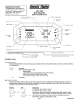
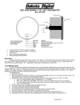
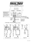
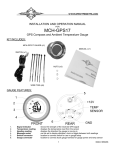
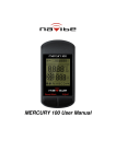
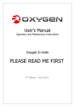
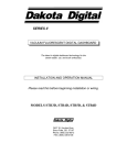
1
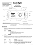
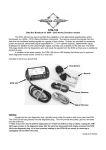
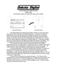
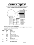
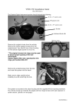
IMPORTANT NOTE! This gauge has an odometer and hour meter preset option that is only available for the first 10 miles (16km) and 1 engine hour of operation. See “preset odometer” and/or “preset hour meter” for instructions. UTV-1500 Gauge for Polaris RZR Tachometer bar graph Speed display 4 Speed unit indicators 3 4x4 on indicator Light sensor location 5 2 6 km/h MPH VOLTS SERV FUEL Message center HR 1 TEMP Gear position indicators A B E OIL Check engine indicator 7 F Fuel bar graph Operation menu Switch functions: Pressing the switch during normal gauge operation will move the message center through the below display functions. Odometer Trip odometer A (hold switch to reset) A Trip odometer B (hold switch to reset) B SERV Countdown service odometer (hold switch to reset) HR Engine hour meter SERV VOLTS HR FUEL TEMP OIL : *not displayed if disabled Countdown service hour meter (hold switch to reset) *not displayed if disabled volt and fuel display *will only display volts if fuel display is disabled Water temp and oil pressure display *display can be disabled if not used, see setup Tachometer readout Clock (hold switch to set) Setting clock: Press and release switch changes current digit Press and hold switch to move to next digit or leave set mode page 1 MAN#650265 INSTALLATION: 1. Disconnect the battery to prevent possible damage to the electrical system or gauge during install. 2. Remove the rubber mounting ring and stock gauge by pushing the gauge out from behind the dash. The UTV gauge will mount in this mounting location. 3. If not installing temp and oil sensor pack (Dakota Digital part number SEN-24-1), skip to step 10. STEPS 4 THROUGH 9: INSTALLATION OF SENSOR PACK (SEN-24-1) 4. Remove the seats, console/engine cover, and center floor/front drive shaft cover (refer to service manual). This allows access to sensor locations on the engine and wire routing locations. 5. Temperature sender installation (NOTE: If engine is warm, allow it to cool before continuing!): a. Remove the bleed screw from the thermostat housing (located on engine behind passenger seat) and set aside. Be prepared to catch any coolant that may drain out. b. Loosen hose clamp and remove coolant hose from thermostat housing. Again, be prepared to catch coolant as this will drain some of the coolant from the system. c. Remove two bolts holding thermostat housing and remove housing from front of engine. (Step 5a) (Step 5b) (Step 5c) d. Install the provided thermostat housing with the original housing bolts. Be careful to position the thermostat correctly into the engine block. Tighten to torque specified in service manual. e. Place hose and hose clamp onto new housing. f. Turn supplied temperature sensor into new housing and tighten with a wrench. DO NOT use Teflon tape or other sealer as this could cause errors in the temperature reading. The sensor should be able to be tightened enough to prevent leaks without having to turn the sensor completely into the housing. g. Insert coolant bleed screw from original housing into the new housing. Tighten to torque specified service manual. h. Connect the spade terminal from supplied harness to the peg on end of temp sensor. (Step 5f) i. 6. (Step 5g) (Step 5h) Refill cooling system. Be sure to check for leaks and proper coolant level after running engine first few times. Check the service manual for the proper coolant filling/bleeding procedure. Oil sender installation: page 2 MAN#650265 a. Turn the provided dual terminal pressure sensor into female end of pressure sensor extension assembly and tighten with appropriate wrenches. Teflon tape or similar sealant may be used to ensure a leak free installation. b. Locate and remove the plug from the pressure check port on the front of the engine. c. Turn the pressure sensor extension assembly into the port and tighten with a wrench. Again, sealant or tape may be used here to prevent leaks. (Step 6a) 7. 8. 9. 10. 11. 12. 13. 14. 15. 16. 17. (Step 6b) (Step 6c) d. Using the provided hose clamp, clamp the sensor body to the seat support frame rail. Check that the sensor will not prevent reinstalling the seat. e. Remove the two thumb nuts and lock washers from the terminals on the sensor. f. Place the one ring terminal from the provided wiring harness onto each of the terminals on the sender and secure with the lock washer and thumb nut. Polarity doesn’t matter so the wires can connect to either terminal. g. Be sure to check engine oil level and add oil if needed. Route the wiring harness from the sensor locations along the seat support frame rail securing with provided plastic ties over to the drivers side of the vehicle. Continue to route the harness under driver’s side floor along the vehicles main harness. Take care to keep the harness away from pinch points or moving parts like the drive shaft. Route the harness up in front of the front cab panel and up to the gauge opening. Secure where needed with provided plastic ties. Sensor pack installation is now complete. See “ENABLING TEMP OIL DISPLAY” in setup notes. Position the provided gauge dash cushion ring onto the back of the UTV-1500. Plug the main gauge harness connector, the speed connector and the sensor harness connector (if used) into the back of the UTV-1500. Place the UTV-1500 into the gauge opening while lining up tab on gauge with the notch in the dash opening. Secure the gauge by placing the provided “L” clamps over the two studs on the back of the gauge with the long legs against the back side of the dash. Secure the clamps and gauge with the provided thumb nuts. Connect battery, turn the key on and verify gauge operation. Start engine and check for oil and water leaks. Shut off engine. If there are no oil or water leaks, reinstall any previously removed floor panels, engine covers and seats as described in the service manual. Installation is now complete. If you experience difficulties check the troubleshooting section in this manual. (Step 6d) (Step 7 and Step 8) (Step 12) SETUP page 3 MAN#650265 Follow the steps below for gauge setup: 1. Press and hold the switch while turning the key on. (If calibrating speed press and hold switch while starting engine.) 2. Release switch. Gauge will scroll through the main menu options. 3. When the desired option is displayed, press and release the switch to enter menu option. 4. Gauge will scroll through submenu options. Press and release the switch to enter submenu option. 5. In submenu option, press and release the switch to change setting. Press and hold switch to save setting. 6. Select “done” from submenu to return to main menu. 7. Select “done” from main menu to leave setup menu. Setup can be left at anytime by turning off key SETUP MENU GUIDE: Release switch to enter setup menu Information menu Displays software version Current software version Displays current speed cal value Current speed cal value Returns to main menu Speed gauge menu Select unit for speed Toggle between MPH and km/h (select unit to use for calibration) Auto calibrate speedometer to a marked mile or kilometer Displays on speed and speed pulses in odometer Press switch to save value and leave setup Adjust speed cal while driving Each press of switch toggles direction of adjustment, value saved after 8 sec no switch Sets value of service odometer set when service odometer is reset Turns off the count down service odometer (default) Sets service to 500 mi or 800 km when resetting service odometer. Service point can be set in 500 mi (800km) increments. Sets service to 7500 mi or 12000 km when resetting service odometer. Returns to main menu SERV ( ) ( ) …. () SERV … Tachometer gauge menu Sets tachometer input type number of cylinders from 1-15 (default 12 for stock tach input) Sets service hour value used when resetting count down service hour meter Service hour meter disabled (default) Minimum service hour set point Service hour reset point can be set in 10 hr increments Maximum service hour set point Returns to main menu Gauge option menu VOLTS Set high voltage warning point (default 15.4V) VOLTS Set low voltage warning point (default 11.1 V) OIL Set low oil pressure warning point (default 9 PSI) TEMP Set high water temp warning point and set temperature unit (default 230F) ( ) Select temp unit, press switch to change, hold switch to save TEMP Select high warning, press switch to change, hold switch to save Returns to main menu SETUP MENU GUIDE (continued): Option menu page 4 MAN#650265 … TEMP OIL FUEL Places gauge into demo mode until the key is turned off (useful for display at shows) Adjust dimming point on gauge Dimming function is off Gauge will dim when light on gauge face is very low (default) 7 selectable dimming levels Gauge will dim early when more light is on gauge face Enables/disables dim output for other gauges Dim output will be high when gauge is dimming Dim output will be disabled (default) Enables/disables display of the temp / oil gauges in message center Temp / oil display is enabled (used if temp and oil senders are not installed) Temp / oil display is disabled (default) Enables/disables display of fuel gauge Fuel gauge will be displayed (default) Fuel gauge is not displayed. This if for use in applications without fuel senders. Allows presetting of odometer value on initial install (not available after 10 miles (16 km) Allows presetting of hour meter value on initial install (not available after 1.0 hrs) Returns to main menu Provides diagnostic modes Displays the resistance in ohms of gear position sender Displays 4x4 coil current in amps Returns to main menu Leaves setup menu if selected ADDITIONAL SETUP NOTES: SPEED – AUTO This setup option allows calibrating to a known mile or kilometer. By default, the speed is calibrated to use the stock RZR speed signal. Calibration should only be needed if the calibration is no longer correct due to changes to tires or gearing. 1. Start with vehicle at the beginning of the marked mile or kilometer and turn the key off. 2. Start engine while holding the switch to enter setup. 3. Select speed option in setup and select appropriate unit (if you will be calibrating to a known kilometer choose km/h, if calibrating to a known mile choose MPH). 4. Select the Auto option. The speed display will read and the message center will read . 5. Begin driving the mile or kilometer. The message center will read the number of pulses read from the speed signal. This value cannot be used to determine if a mile or kilometer has been driven. 6. At the end of the mile or kilometer, stop the vehicle and press the switch to save the new speed calibration. The gauge will leave setup and return to normal operation. SPEED – ADJUST This setup option allows adjustment to speed while driving. By default, the speed is calibrated to use the stock RZR speed signal. Calibration should only be needed if the factory calibration is no longer correct due to changes to tires or gearing. 1. Start vehicle while holding the switch to enter setup. 2. Select speed option in setup and select appropriate unit (if you will be calibrating in kilometers per hour choose km/h, if you will be calibrating in miles per hour choose MPH). 3. Select the option. The speed reading will displayed and message center will read 4. Follow another vehicle traveling at a constant known speed or use a GPS unit to determine your speed. Hold the switch to begin increasing the speed reading. To decrease the speed reading, release the switch and press and hold the switch again. 5. The direction of adjustment will change each time the switch is released. 6. The calibration is saved when the switch has not been pressed for approximately 8 seconds. This is indicated by a short flash of the message center. 7. Calibration can continue after a save has occurred but you must then wait another 8 seconds for the new setting to be saved. 8. To leave speed adjust mode, stop the vehicle and turn off the key. SERVICE METERS page 5 MAN#650265 This gauge has two service meters. These are a countdown hour meter and a countdown odometer. Both service meters can be disabled, or enabled independently. This allows for setting of two individual service points, one based on engine run time, the other based on odometer. When the setup point is reached, SERV will be displayed. Pressing the switch will clear the message until the next time the key is turned on. Once the service has been done, use the switch to select the service meter that is due (display will show a negative value or zero). Then press and hold the switch to reset the service meter to the value set in setup. The service meter can be disabled by selecting in setup. If a new value is set for the service meter, and the meter was previously disabled, the service message may immediately be displayed. Reset the service meter to begin a new countdown. DIM OUT ( ) The dim out option allows the dim output to be turned on or off. The dim output is used if you have installed other Dakota Digital gauges and would like this gauge to also control the dimming of these gauges. If the dim out option is turned on, 12v is sent out on the dim out wire when the gauge is dimming. In this mode, the gauge will be either in dim mode or full brightness mode. If no other gauges are to be dimmed (typical installation), this option can be set to off. In this mode the gauge will fade when dimming and gauge dimming will be less noticeable. This option is set to off by default. PRESET ODOMETER ( ) Within the first 10 miles (16km) after first installing the gauge, this option is available in the option menu. Selecting this option will allow a ONE TIME preset of the odometer to the reading of the stock gauge. If this setting is not used within the first 10 miles (16km) or an incorrect setting has been saved, the gauge will need to be returned to Dakota Digital for any odometer adjustment. The procedure to preset the miles is as follows: 1. Select from option menu in setup. 2. Verify that desired unit (MPH or km/hr) is displayed above message center. If not, turn off key to leave setup and use unit option under speed to set correct unit. NOTE: Preset MUST be done with correct unit or odometer will not be set correctly! 3. The current odometer value is displayed with the first digit blinking. 4. Press and release the switch to change the current digit. Press and hold the switch to move on to the next digit. 5. Repeat step 4 until all digits are set. After tenths digit is set, press and hold switch. 6. Speed display will read . Check the current unit and the odometer to make sure it is correct. If not, press and hold the switch to go back to change it. 7. NOTE: Check the displayed odometer value VERY carefully before next step. After selecting yes, you will no longer be able to change the odometer. 8. If the settings are all correct, press and release the switch. Speed display will now read 9. Press and hold the switch to preset the odometer. PRESET HOUR METER ( ) Within the first 1.0 engine hours after first installing the gauge, this option is available in the option menu. Selecting this option will allow a ONE TIME preset of the hour meter to the reading of the stock gauge. If this setting is not used within the first 1.0 engine hour or an incorrect setting has been saved, the gauge will need to be returned to Dakota Digital for any hour meter adjustment. The procedure to preset the miles is as follows: 1. Select from option menu in setup. 2. The current hour meter value is displayed with the first digit blinking. 3. Press and release the switch to change the current digit. Press and hold the switch to move on to the next digit. 4. Repeat step 3 until all digits are set. After tenths digit is set, press and hold switch. 5. Speed display will read . Check the hour meter reading to make sure it is correct. If not, press and hold the switch to go back to change it. 6. NOTE: Check the displayed hour meter value VERY carefully before next step. After selecting yes, you will no longer be able to change the hour meter. 7. If the settings are all correct, press and release the switch. Speed display will now read 8. Press and hold the switch to preset the hour meter. GAUGE WARNINGS When a set warning point, set in setup menu, is reached for any of the gauge readings, the message center will display and flash the reading that is at a warning point. Other message center functions are still available with the switch but the gauge will return back to the warning display as long as the gauge is at a warning point. A “” warning will also be displayed if the high temp signal is sent from the RZR regardless of the gauge reading. ENABLING TEMP AND OIL DISPLAY page 6 MAN#650265 A temp sensor and an oil pressure sensor along with the needed hardware and harness to install them are an optional accessory package (SEN-24-1) for the gauge. These provide additional gauge functions that are not included on the stock RZR gauge. If this sensor pack is installed, the display of these gauge values needs to be enabled. To do so, enter the setup menu and select the “” menu. Then select the “ TEMP OIL” option and change the setting from “” to “”. ENGINE CODE READOUT As with the stock gauge, the UTV-1500 provides a readout of engine codes when the key is cycled from off-on-off-on-offon. Engine codes will flash on the check engine light and the message center will display “” until a complete engine code is received. Each received code number will then be displayed in the message center. When the end of the engine code list is reached, “” will be displayed. If no engine codes are available, “” will be displayed right away. FUEL GAUGE This gauge has two fuel gauge displays. The primary display is a bar graph along the bottom of the gauge. This displays the fuel level relatively between empty and full. The second is a percentage of full reading accessed in the message center using the switch. At a reading of approximately %10 the fuel bar will begin to flash as a warning. Also the percent full reading will be displayed in the message center. Pressing the switch will allow the message center to return to other displays. The fuel bar will continue to flash until fuel is added. For some applications, there is no fuel sender and so there is no fuel gauge data available. For these applications, the fuel gauge display can be disabled using the “ FUEL” option in setup. DIAG MENU Some diagnostic options are available in the setup routine to allow checking certain inputs to the gauge. The “” option will display the resistance in ohms seen at the gear sender input. This can be used to troubleshoot problems with the gear sender. The “ ” option provides a readout of the current flowing in the 4x4 coil in amps. This can be used to troubleshoot problems with the 4x4 coil wiring and dashboard switch. Refer to the vehicle’s service manual for troubleshooting guidance. TROUBLESHOOTING PROBLEM Gauge does not light up CAUSE Gauge has bad ground or power Tach bar always stays blank Tach reads incorrectly Speed reads incorrectly Gauge does not dim Gauge is always dim Tach wire is not connected properly Engine value set incorrectly Engine value set incorrectly Speedometer needs to be recalibrated Dim level is set to off or set too low Dim level is set too high Light sensor right of speed is covered No sender connected, or incorrect sender selected. is displayed in oil, or water display SOLUTION Check connections to wiring harness and check wiring harness and gauge wires for pinched or broken wires. Check for good connection to main harness Set Engine value to 12 for stock installation Set Engine value to 12 for stock installation See setup for speed calibration instructions. Set dim level to higher level (see setup) Set dim level to lower level (see setup) Make sure right side of lens is not covered. Check proper connection to sender. Check for broken or pinched sensor wires. For water temp sender, check for good ground and remove any sealant tape on threads of sender. is displayed in fuel, oil or water display. Sensor wire is shorted to ground. Fuel bar always shows full and fuel display reads “” Vehicle does not have a fuel sender. Wiring to fuel sender is disconnected or broken. PROBLEM ENG light is flashing and CAUSE Engine computer is indicating the page 7 If temp and oil senders are not installed, temp and oil display can be disabled (see setup). Check sensor wire harness for correct connection to sensor. Check for pinched or broken sensor wire harness. Disable fuel display using setup option. Check connections to fuel sender and wiring harness for loose connections or broken wires and repair. SOLUTION Turn engine off and allow to it cool. Determine and MAN#650265 is flashing in message center SERV is flashing in the message center Temp / oil screen will not display Message center jumps to a screen and blinks Can not get into setup / can not change message center display Gauge always starts in setup Speedometer reads low or does not read a speed Speedometer reads high. engine is over heating. correct cause of engine overheating. One of the countdown service meters has reached zero Perform service and reset service meter by holding switch when service meter is displayed. If service meter operation is not desired, disable service meter by setting to in the setup menu. In setup menu change the option “ TEMP OIL” to “” If a warning is not desired for this reading, change the warning point under “” in setup. Check switch and wiring for breaks in the wire or loose connections. Temp / oil display is disabled. A warning has occurred with the blinking reading. Switch disconnected Switch wire shorted to ground. Check wire to switch for shorts or pinched wires. Speed calibration is too high for vehicle. Speed calibration is too low for vehicle. Recalibrate speedometer. See speed auto or speed adjust in setup notes. Recalibrate speedometer as described in setup. SERVICE AND REPAIR DAKOTA DIGITAL offers complete service and repair of its product line. In addition, technical consultation is available to help you work through any questions or problems you may be having installing one of our products. Please read through the Troubleshooting Guide. There, you will find the solution to most problems. Should you ever need to send the unit back for repairs, please call our technical support line, (605) 332-6513, to request a Return Merchandise Authorization number. Package the product in a good quality box along with plenty of packing material. Ship the product by UPS or insured Parcel Post. Be sure to include the RMA number on the package, and include a complete description of the problem with RMA number, your full name and address (street address preferred), and a telephone number where you can be reached during the day. Any returns for warranty work must include a copy of the dated sales receipt from your place of purchase. Send no money. We will bill you after repair. Dakota Digital 24 Month Warranty DAKOTA DIGITAL warrants to the ORIGINAL PURCHASER of this product that should it, under normal use and condition, be proven defective in material or workmanship within 24 MONTHS FROM THE DATE OF PURCHASE, such defect(s) will be repaired or replaced at Dakota Digital’s option. This warranty does not cover nor extend to damage to the vehicle’s systems, and does not cover removal or reinstallation of the product. This Warranty does not apply to any product or part thereof which in the opinion of the Company has been damaged through alteration, improper installation, mishandling, misuse, neglect, or accident. This Warranty is in lieu of all other expressed warranties or liabilities. Any implied warranties, including any implied warranty of merchantability, shall be limited to the duration of this written warranty. Any action for breach of any warranty hereunder, including any implied warranty of merchantability, must be brought within a period of 24 months from date of original purchase. No person or representative is authorized to assume, for Dakota Digital, any liability other than expressed herein in connection with the sale of this product. 4510 W. 61ST St. N., Sioux Falls, SD 57107 Phone: (605) 332-6513 FAX: (605) 339-4106 www.dakotadigital.com [email protected] ©Copyright 2009 Dakota Digital Inc. page 8 MAN#650265