1
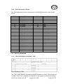
5.2.8 Make sure that pin one on the cable, on the SCSI controller and on
the SC35 are correctly aligned. The SC35 uses a square pad on the
connector to indicate pin one, and most cables are marked with a triangle
on the connector or a stripe on the cable itself to indicate the first pin.
5.2.9 Attach the power cable from the system power supply to the SC35.
This cable is keyed and cannot be inserted backwards. At this point,
installation is complete.
5.2.10 Reattach the AC power cable to the system and power-up.
5.3 Power and Cable Attachments
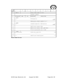
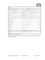
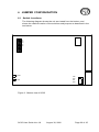
The following diagram depicts the SC35 as viewed from the connector (Back
View). Pin 1 of the SCSI interface and the power connections are as labeled.
Pin #1
V
C
C
G G V
N N D
D D D
VCC = +5.00 volts +/- 5%
GND = 0 volts
VDD = +12.00 volts (or no connection)
Figure 1:
Back view of SC35
5.4 Software Installation Procedure
With the SC35 installed, the user can now treat the device as a standard
Direct Access SCSI device. Standard implementation of the SC35 will include
building a partition table with FDISK and high-level formatting. Low level
formatting is not required, nor recommended. Refer to your system
documentation for detailed instructions.
SC35 User Guide Ver 4.8
August 30, 2002
Page 21 of 25