1
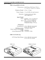
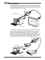
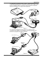
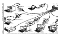
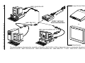
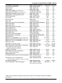
User's Manual
RGB 118 & RGB 118 Plus
Computer-Video Interfaces
Contents
Introduction to the RGB 118 & RGB 118 PLUS ................................. Chapter 1
Introduction .......................................................................................... 1-1
About this Manual ......................................................................... 1-1
Features ....................................................................................... 1-1
Specifications ............................................................................... 1-2
Operation of RGB 118 & RGB 118 PLUS ........................................... Chapter 2
Front Panel .......................................................................................... 2-1
Top Panel ............................................................................................ 2-2
Internal DIP Switches .......................................................................... 2-3
Opening the RGB 118 & RGB 118 PLUS Case ........................... 2-3
Changing a Switch Setting ........................................................... 2-3
Setting Internal DIP Switches ....................................................... 2-3
Using the SRI (RGB 118 PLUS only) .................................................. 2-5
Applications ......................................................................................... Chapter 3
Applications ......................................................................................... 3-1
Application Diagrams ................................................................... 3-2
RGB 118/MBC VGA/XGA HR ............................................... 3-2
RGB 118 PLUS/MBC SPARC Buffer .................................... 3-2
RGB 118 PLUS/Hi Res ECL Buffer ....................................... 3-3
RGB 118/RGB 118 PLUS/SW 2 AR Switcher ....................... 3-3
Multiple RGB 118 & RGB 118 PLUS w/switcher ................... 3-4
118 PLUS Kit ......................................................................... 3-5
Other Reference Material .................................................................. Appendix A
Computer Compatibility and MBC Cables .......................................... A-1
Accessories and Part Numbers .......................................................... A-2
Glossary ............................................................................................. A-3
RGB 118 & RGB 118 PLUS
User’s Manual
68-059-01
Rev. F
69-08
Page i
Legend of Icons
The following icons may be used in this manual:
___ Important information – for example, an action or a step that must
be done before proceeding.
___ A Warning – possible damage could occur.
_ A Note, a Hint, or a Tip that may be helpful.
__ Possible Electrostatic Discharge (ESD) damage could result from
touching electronic components.
__ Additional information may be referenced in another section, or in
another document.
Extron • RGB 118 & RGB 118 PLUS • User’s Manual
Extron’s RGB 118 & RGB 118 PLUS
User’s Manual
1
Chapter One
Introduction to the
RGB 118 & RGB 118 PLUS
COMPUTER-VIDEO INTERFACES
Introduction
Features
Specifications
Extron • RGB 118 & RGB 118 PLUS • User’s Manual
Introduction to the RGB 118 & RGB 118 PLUS
Introduction
About This Manual
This manual contains connection, operation and application
information for the RGB 118 and RGB 118 PLUS universal
interfaces.
RGB 118 & RGB 118 PLUS Facts and Features
The Extron RGB 118 and RGB 118 PLUS are Universal
Computer-Video Interfaces compatible with computer monitor
video signals such as CGA, EGA, VGA, MCGA, IBM PS/2, MAC II,
Super VGA and more. Providing an RGB bandwidth range of 150
MHz (rise and fall time of 4 nS) and a horizontal frequency range
of 15-100 kHz, the RGB 118 and RGB 118 PLUS allow any
compatible computer to be connected via simple MBC or ICWK
input cable change.
Features
·
Universal compatibility
·
120 MHz RGB video bandwidth (-3db)
·
LED power indicator
·
Horizontal centering with ON/OFF switch
·
Three position peaking/sharpness and gain control switch settings
·
Variable gain controls (R,G,B)
·
Serration pulse removal switch
·
Sync on green switch for output
·
Automatic sync stripping from RGB
·
Blue enhancement (TTL only)
·
MBC power output jack
·
External control knobs
·
Metal enclosure
·
MBC interface cable required
·
Simple installation and operation
*
LCD scan-rate display of horizontal and vertical frequencies
*
SRI – holding the RGB 118 PLUS up to the face of a computer’s
monitor will display the horizontal and vertical scan-rates on the
LCD readout without any attached input cables.
*
Vertical centering with ON/OFF switch
* The bottom three features apply only to the RGB 118 PLUS
Page 1-1
Extron • RGB 118 & RGB 118 PLUS • User’s Manual
Introduction to the RGB 118 & RGB 118 PLUS
Specifications
RGB 118 and RGB 118 PLUS
Dimensions .. 4.63” W x 4.75” D x 1.75” H
.. 11.7cm W x 12cm D x 4.4cm H
Shipping Weight .. 4 lbs. (1.8 kg)
Power Supply .. 12 volt 800 mA (wall mount)
Warranty .. 2 years parts and labor
.. (See Appendix)
Input Signal
Video .. Analog: .5 to 1.2 volts p-p
.. ECL: .8 to 1.0 volts p-p
Sync .. TTL: .3 to 5.0 volts p-p
.. Separate Sync TTL (±)
.. Composite Sync TTL (±)
Frequency
Compatibility .. 15 to 100 kHz horizontal
.. 30 to 150 Hz vertical
RGB Bandwidth .. 120 MHz (-3db)
Video Amplifier Bandwidth
(VAB) .. 200 MHz
Actual Bandwidth (AB) .. 120 MHz (-3db)
RGB 118 PLUS only
LCD Scan-Rate Range .. 10 to 125 kHz horizontal
.. 30 to 200 Hz vertical
RGB 118
Extron • RGB 118 & RGB 118 PLUS • User’s Manual
RGB 118 PLUS
Page 1-2
Extron’s RGB 118 & RGB 118 PLUS
User’s Manual
2
Chapter Two
Operation of RGB 118 & RGB 118 PLUS
Front Panel
Top Panel
Internal DIP Switches
Using the SRI
Extron • RGB 118 & RGB 118 PLUS • User’s Manual
Operation
Operation of RGB 118 and RGB 118 PLUS
Front Panel
The following descriptions are keyed* to the RGB 118 PLUS
drawings below and on the facing page.
A SRI Pushbutton Switch (RGB 118 PLUS ONLY)
Push and hold this button in to enable the RGB 118 PLUS SCANRATE LCD to display the horizontal and/or the vertical scan rate
frequency of a monitor (See Using the SRI on Page 2-5 for details).
B Vertical Center Control (RGB 118 PLUS ONLY)
Turning this RGB 118 PLUS control shifts the displayed image up
or down if the Vertical Center Switch is in the ON position.
C Vertical Center Enable Switch (RGB 118 PLUS ONLY)
Enable/disable the RGB 118 PLUS Vertical Center Control – OFF
position disables and ON position enables.
D MBC Power Connector
Provides 12 VDC for Extron MBC Buffers.
E Universal 9 Pin Input Connector
The RGB 118 and RGB 118 PLUS video input is supplied through
this connector. Acceptable input types are TTL, Analog and ECL.
Connector pin assignments follow:
Pin # ANALOG
DIGITAL (TTL or ECL)
1
Ground
Ground
2
No Connection
Red Prime
3
Red
Red
4
Green/Sync on Green
Green
5
Blue
Blue
6
No Connection
Green Prime
7
No Connection
Blue Prime
8
Horizontal/Composite Sync
Horizontal Sync
9
Vertical Sync
Vertical Sync
F Horizontal Center Enable Switch
Enable/disable the Horizontal Center Control – Off position disables
and ON position enables.
G Horizontal Center Control
Turning this control shifts the displayed image to the left or right.
* – Letters next to the descriptions are keyed to the circled letters in the
drawings on this and the next page.
Page 2-1
Extron • RGB 118 & RGB 118 PLUS • User’s Manual
Operation
Top Panel
H
Blue Enhance Control (Valid for TTL input only)
This control allows adjusting a blue text display to an easier to read
blue-green color.
I
Scan Rate Indicator (SRI) LCD Panel (RGB 118 PLUS ONLY)
The LCD panel displays a monitor’s horizontal or vertical scan rate
frequency.
J
V = Vertical Scan Rate (RGB 118 PLUS ONLY)
Indicates vertical scan rate is currently being monitored.
K H = Horizontal Scan Rate (RGB 118 PLUS ONLY)
Indicates Horizontal scan rate is currently being monitored.
L Peak Switches (All three switches must be set to same position.)
· Normal – Input to output signal = unity gain (gain = 1)
· Boost (Long Line Level Peaking) – Boost and Peak all frequencies
· High Frequency Peaking – Decreases “fuzziness” or “streaking”
associated with interfacing high frequency computers.
M Output BNC connectors (located on rear panel)
1 = R = RED video output
2 = G = GREEN video output
3 = B = BLUE video output
4 = S = Sync output
Extron • RGB 118 & RGB 118 PLUS • User’s Manual
Page 2-2
Operation
Internal DIP Switches
Internal DIP switch settings determine the operating mode of the
RGB 118 and RGB 118 PLUS. Changing the switch settings
requires removal of the top and bottom halves of the case as
described below.
Opening the RGB 118 or RGB 118 PLUS Case
To open the RGB 118 or RGB 118 PLUS case, remove the screw
from the bottom of the case (see Figure 1 on facing page). This
enables removal of the top and bottom halves of the case as
shown in Figure 2.
Changing a Switch Setting
The switches on the DIP switch module used in the RGB 118 and
the RGB 118 PLUS are the slide type (see drawing, Figure 3 on
facing page). To change the position of the slide switch, a small
screw-driver is used to push (slide) the switch to the desired
position (enable or disable).
Setting Internal DIP Switches
Internal DIP switches SW3-1,2, SW4-1, 2, 3 and SW5-1,2 affect
RGB 118 and RGB 118 PLUS operation as follows:
SW3-1 SW3-2 Serration/LCD Switch
F1 OFF
OFF Normal – Serration pulses remain w/output sync
OFF
ON
Serration pulses are removed from output sync 2
SW4-1 SW4-2 SW4-3
OFF OFF
F1 ON
ON
OFF ON
OFF
ON
ON
Analog Output Switch
Normal
Sync on Green 3
Sync on Mono 4
SW5-1 SW5-2 TTL Mode Switch
F1 OFF
OFF Normal
ON
OFF 64 Colors < 18 KHz
X
ON
16 Colors > 18 KHz
Notes:
1. F = Factory setting
2. Required by some projectors
3. When setting the RGB 118 for Sync on Green, you must also
disconnect the BNC cable from the external “Sync” output of the
RGB 118 and RGB 118 PLUS. Otherwise, sync is output on both
green and the composite sync output which may cause
abnormal levels of green to appear on the presentation display.
4. Monochrome Composite – Use the Green output only.
Page 2-3
Extron • RGB 118 & RGB 118 PLUS • User’s Manual
Operation
Figure 1
Figure 2
Figure 3
Extron • RGB 118 & RGB 118 PLUS • User’s Manual
Page 2-4
Operation
Using the SRI (RGB 118 PLUS only)
The SRI feature of the RGB 118 PLUS is used to determine the
approximate horizontal and vertical scan frequencies of video and
computer monitors. To use the SRI, hold the RGB 118 PLUS with
the feet against the face of the monitor and near the center of the
screen as shown in Figures 1 and 2 below.
To view the vertical scan frequency, hold the unit so the LCD
readout is on a vertical plane (red SRI button is in the uppermost
position) as shown in Figure 1. Wait until the green Vertical (V)
LED turns on, then push and hold the red SRI button in until a
readout is obtained.
To view the horizontal scan frequency, hold the RGB 118 PLUS so
the LCD readout is on a horizontal plane (normal viewing) as
shown in Figure 2. When the red Horizontal (H) LED turns on,
push and hold the red SRI button in until a readout is obtained.
Anti-static, anti-glare or EMI coatings on the face of the CRT may
prevent the RGB 118 PLUS SRI from displaying the monitor’s
scan frequencies properly. Should this occur, an alternate method
to obtain a readout is to set the RGB 118 PLUS on top and toward
the rear of the monitor as shown in Figures 3 and 4 below. To
view the vertical scan frequency using this method, set the RGB
118 PLUS as shown in Figure 3 with the red SRI button toward the
rear of the monitor. Press and hold the red SRI button in when the
green Vertical (V) LED turns on. To view the horizontal scan
frequency, set the RGB 118 PLUS on the monitor as shown in
Figure 4. When the red Horizontal (H) led turns on, press and hold
the red SRI button until a readout is obtained.
Checking monitor Horizontal Scan Rate using the RGB 118 PLUS SRI
Checking monitor Vertical Scan Rate using the RGB 118 PLUS SRI
Red
SRI
Button
Figure 1
Figure 2
Red
SRI
Button
Figure 3
Page 2-5
Figure 4
Extron • RGB 118 & RGB 118 PLUS • User’s Manual
Extron’s RGB 118 & RGB 118 PLUS
User’s Manual
3
Chapter Three
RGB 118 & RGB 118 PLUS
Applications
Extron • RGB 118 & RGB 118 PLUS • User’s Manual
Applications
Applications
Following are possible applications for the RGB 118 and/or the
RGB 118 PLUS.
1. As a Sync Stripper
Using an MBC RGBS cable1, the RGB 118 can be used to strip
Sync from Green and separate to Green and Composite Sync
outputs.
• Connect the RGB with sync on green signal to MBC RGBS cable.
• Insert the MBC RGBS cable into the 9 pin input of the RGB 118.
• Use the video and sync outputs of the interface as normal.
2. Add Sync on Green
The RGB 118 can be used to add either composite or separate
Horizontal and Vertical (HV) sync to the green video channel. Use
the MBC RGBS cable1 to add composite sync or the MBC RGBHV
cable2 to add separate H&V sync.
• Connect the RGBS signal to the MBC RGBS cable or the RGBHV
signal to the MBC RGBHV cable.
• Insert either of the MBC cables into the 9 pin Universal input of the
RGB 118.
• Use the instructions found on page 2-3 to add sync on green.
• Use only the RGB outputs of the interface.
3. As a Sync Combiner
Using the MBC RGBHV cable2 the RGB 118 can be used to
combine separate horizontal and vertical sync to composite sync.
• Connect the RGBHV signal to the MBC RGBHV cable.
• Insert the MBC RGBHV cable into the 9 pin Universal input of the
RGB 118.
• Use the Sync output of the interface as a composite sync.
4. Mono Composite
The RGB 118 can be used to convert any video signal to
monochrome composite while maintaining resolution.
• Connect any video signal to the MBC RGBS cable1.
• Insert the 9 pin of the MBC RGBS cable into the Universal 9 pin
input of the RGB 118.
• Use the instructions found on page 2-3 to convert the signal to
monochrome composite.
5. Frequency Indicator
The RGB 118 can be used as a Horizontal or Vertical frequency
indicator of any monitor.
Simply hold the RGB 118 PLUS up to the face of the monitor glass
and hold in the SRI button on the front panel of the interface. The
Horizontal and Vertical scan frequencies will automatically be
displayed on the LCD. Refer to page 2-5.
NOTES: 1. MBC RGBS cable: 4 BNC to 9 pin, Part #26-213-01
2. MBC RGBHV cable: 5 BNC to 9 pin, Part #26-270-01
Page 3-1
Extron • RGB 118 & RGB 118 PLUS • User’s Manual
Applications
Application Diagrams
The application diagram below (Figure 1) demonstrates an RGB
118 Interface used to interface a PC Computer monitor to a large
screen data monitor which could be located in the same room or in
a different location up to 150’ away.
RGB 118
MBC VGA/XGA HR
Large Screen
Data Monitor
Figure 1
The application diagram below (Figure 2) demonstrates an RGB
118 PLUS combined with an MBC SPARC Buffer to interface a
high resolution computer/monitor workstation to a large screen
projector. The MBC SPARC Buffer is used to allow the higher
resolution signals to be transmitted with minimum signal loss and
no reflections or signal ghosting. The MBC SPARC Buffer gets its
power from the RGB 118 PLUS through the MBC Power jack.
RGB 118 PLUS
MBC
SPARC
BUFFER
NeXT Color Computer,
Sun SparcStation,
SGI WorkStation
Large
Screen
Projector
Figure 2
Extron • RGB 118 & RGB 118 PLUS • User’s Manual
Page 3-2
Applications
The application diagram below (Figure 1) demonstrates an RGB
118 PLUS combined with a Hi Res ECL Buffer and an MBC SUN/
APOLLO MONO cable to interface a high resolution computer/
monitor workstation to a large screen projector.
RGB 118 PLUS
Large
Screen
Projector
Hi Res
ECL Buffer
MBC
SUN/APOLLO MONO
Cable
SUN/APOLLO MONO
Workstation
Figure 1
The application diagram below (Figure 2) consists of two
computers with RGB 118 and RGB 118 PLUS interfaces with
access to a projector through a switcher.
RGB 118
MBC VGA/XGA HR
RGB 118
PLUS
MBC MAC/QUADRA HR
Large
Screen
Projector
Figure 2
Page 3-3
Extron • RGB 118 & RGB 118 PLUS • User’s Manual
MBC IBM PCC
Laptop
Computer
LBC VGA
RGB 118
PC
Computer
RGB 118
PLUS
RGB 118
RGB 118
MBC VGA/XGA HR
PC
Computer
Large
Screen
Projector
RGB 118
PLUS
MBC
SPARC
BUFFER
Page 3-4
NeXT,
SGI
or
SUN
WorkStation
MBC IBM
VGA/XGA HR
IBM PS2
Computer
MBC
MAC/QUADRA HR
MAC
Computer
Six different computer systems with RGB 118 and RGB 118 PLUS interfaces all have access to a projector through an Extron switcher in this application.
Applications
Extron • RGB 118 & RGB 118 PLUS • User’s Manual
Extron Switcher
RGB 118
Page 3-5
Large Screen Data Projector
MBC VGA/XGA HR
RGB 118 PLUS
Universal Interface
or
MBC MAC/QUADRA HR
Data Monitor
The above diagram illustrates the versatility of Extron’s 118 PLUS KIT (P/N in Appendix) which includes the following items:
RGB 118 PLUS – MBC VGA/XGA HR – MBC MAC/QUADRA HR – MBC IBM PCC – T-VGA – MAC DFTA – BNC-4-12’ HR
Applications
Extron • RGB 118 & RGB 118 PLUS • User’s Manual
MBC IBM PCC
Extron’s RGB 118 & RGB 118 PLUS
User’s Manual
A
Appendix A
Other Reference Material
Computer Compatibility and MBC Cables
Accessories and Part Numbers
Glossary
Limited Warranty
Extron • RGB 118 & RGB 118 PLUS • User’s Manual
Computer Compatibility and MBC Cables
Compatible Computers
Amiga 500,1000,2000
Apple IIE/IIC
Apple IIGS
Apple Mac RGB (Internal Wiring Kit)
Apple Mac SE RGB (Internal Wiring Kit)
Apple Mac II Series (Standard Card)
Apple Mac II w/ SuperMac Card
AT&T 6300/6310
AT&T 630
Burroughs 25
DEC 340
IBM 3161,3163,3191,3196 Mono
IBM 3162 Mono
IBM 3164 Color
IBM 3179,3192,3197 Color
IBM 3192D Color
IBM 3270 PC Color
IBM 3270 PCG Color
IBM 3290 Color
IBM 3471/3476 Infowindow
IBM 3472/3477 Terminals
IBM 5291 M-2
IBM PC or Compatible w/ CGA or EGA card
IBM PC,XT,AT & Compatible w/ MDA Card
IBM PC,XT,AT & Compatible w/ PGA Card
IBM PS/2 VGA
IBM PS/2 w/ 8514/A Card
IBM VGA/Super VGA/XGA or VGA Plus
Any Laptop w/ VGA output *
(has no external monitor)
NCR PC 6,8 Color
NeXT Monochrome Computers
NeXT Color Computers
Sigma 400 Color
Sun/Apollo Monochrome 9D Workstations
MBC Cable Required
Horz. kHz
MBC Amiga 2000
15.7
MBC Apple IIE
15.7
MBC Mac II HR
15.7
ICWK Mac RGB
22.3
ICWK Mac SE RGB
22.0
MBC Mac II HR
35.5
MBC SuperMac
35-48
MBC AT&T 6300
26.0
MBC AT&T 630
54
MBC B-25
19.8
ICWK DEC 340
31.5
MBC 3161/63/91/96 Mono 27.6
MBC IBM 3162
25.9
MBC IBM 3164
27.6
MBC 3179/92/97
23.0
MBC 3192D
23.0
MBC IBM 3270 PC
23.5
MBC IBM 3270 PCG
24.0
MBC IBM 3290
29.6
ICWK 3471/3476
31.0
MBC IBM INFOWINDOW
38.0
MBC 5291 M-2
18.3
MBC IBM PCC
15.7/21.8
MBC IBM PCM
18.4
MBC IBM PGA HR
31.5
MBC IBM PS/2
31.5/35.5
MBC IBM VGA HR
35.1
MBC IBM VGA HR
31.5-<50.0
LBC VGA HR
31.5
Vert. Hz
60
60
60
60
60
67
67
60
60
60
60
65
65
65
60
60
63
63
73
60
68
50
60
50
70
60/70
87/43
60/80
60/70
23.6
62.0
63.0
31.4
63.8
55
68
68
60
66
MBC RGB BUFFER
64.0-<125.0
60
MBC Sparc Buffer
MBC XEROX 6085
64-89
28.0/37.0
60/70
76
MBC NCR PC 6,8
MBC NeXT Cable
MBC Sparc Buffer
MBC Sigma 400
MBC SUN/APOLLO
(also requires ECL Buffer)
Sun/Apollo Color Workstations
or any Workstation w/RGB out on BNC Connectors.
Sun Sparc Stations
Xerox 6085 and 1186 Computers
(also requires Xerox Buffer)
*When using most laptops to display on large-screen projectors, the computer’s internal LCD display is
deactivated.
Page A-1
Extron • RGB 118 & RGB 118 PLUS • User’s Manual
Accessories and Part Numbers
Extron Part
Part Number
RGB 118 (115 Volt) ................................................................. 60-080-01
RGB 118 (230 Volt) ................................................................. 60-080-02
RGB 118 PLUS (115 volt) ....................................................... 60-080-05
RGB 118 PLUS (230 volt) ....................................................... 60-080-06
118 PLUS Kit (115 volt) ........................................................... 42-018-01
118 PLUS Kit (230 volt) ........................................................... 42-018-02
Extron • RGB 118 & RGB 118 PLUS • User’s Manual
Page A-2
Glossary
Glossary
Bandwidth - For video amplifiers, bandwidth is a measure of the
range of frequencies that make up the components of video
character information within which a video amplifier will respond.
The frequency range (passband) is usually measured between the
half-power (3-dB) points on the video amplifier amplitude output
response vs. frequency curve for a wide range of frequencies
while maintaining a constant input signal amplitude for each
frequency.
CGA - Color Graphics Adapter. Inroduced in 1983, it was IBM's first
product to display both color and graphics. An RCA jack above
the 9 pin video output connector provides NTSC video. Signal
type is TTL, non-interlaced, with Pixel x Line resolution of 640 x
200 and a color palette of 4/16. CGA has a horizontal scan
frequency of 15.75 kHz and vertical frequency of 60 Hz.
Data Monitor - A monitor with horizontal scan capability between
15.75-36(42) kHz. Data monitors and projectors are commonly
associated with NTSC video, IBM CGA through VGA and Apple/
Macintosh computer input sources.
ECL - Emitter Coupled Logic. ECL signals are high speed digital logic
and are mostly found in high resolution CAD/CAM computers and
are usually monochrome or black and white. ECL operates in two
level states and switches between these states in small
increments of time. Bits are: Next/Most/Least Significant.
Conversion to analog is required for proper interfacing.
EGA - Enhanced Graphics Adapter. Introduced by IBM in 1984, the
EGA card may be configured with dip switch settings to provide an
MDA or CGA output signal. Signal type is TTL, non-interlaced
with a Pixel x Line resolution of 640 x 350 and a color palette of
16/64. EGA horizontal scan frequency is 21.8 kHz or 15.75 kHz in
CGA mode. Vertical frequency is 60 Hz. The EGA card outputs
to a 9 pin “D” type connector.
Graphics Monitor - A monitor with horizontal scan capability from
15.75-75 (80) kHz. Graphic monitors and projectors accept input
from NTSC Video and CGA- VGA, as well as, high resolution
computers and CAD/CAM workstations.
ICWK “Internal Computer Wiring Kit”- ICWK kits provide interfacing
signals for computers and terminals with no external video display
output. Internal video monitor signals are routed externally from
the terminal, usually to a 9 pin connector. From the 9 pin
connector, a short cable is included with the kit for signal transfer
to the interface 9 pin connector input.
MBC “Monitor Break-out Cable” - A cable used to view a local
monitor or terminal while simultaneously routing the computer
signal to a new source, such as a data projector or monitor. The
cable contains a male and female video connector, either piggybacked to each other or provided as a Y type cable.
Page A-3
Extron • RGB 118 & RGB 118 PLUS • User’s Manual
Glossary
Peaking - Peaking compensates for mid and high frequency RGB
Video Bandwidth response in data monitors and projectors and for
signal losses due to cable capacitance. When using the Peak
enhancements on the RGB 118 and RGB 118 PLUS interface,
please use the following guidelines for proper output settings:
__ Use with all computer frequencies between 15-125 kHz at any
cable length.
__ Use with high frequency computers of 36 kHz or higher with cable
lengths 75 feet or greater.
Serration - A vertical synchronizing pulse divided into a number of
small pulses, each acting for the duration of half a line in a
television system. Serrations are used to keep the horizontal
oscillator synchronized during the vertical sync pulse interval.
Sync - The synchronization signals or timing pulses which lock the
electron beam in step, both horizontally and vertically, with the
image signal. Also called Composite Sync, this signal is derived
from a composite or combination of horizontal and vertical drives,
with some slightly narrowed and delayed pulses, as well as, the
addition of equalizing pulses. It is one of the more popular signals
used in video systems today and when used is usually
accompanied by subcarrier.
TERMINATOR - A resistor at the end of a coaxial cable or line used
to match the impedance of the equipment being used. The
resistor absorbs signal energy to prohibit signal reflections back to
the source. This causes the source equipment to operate as if the
line is connected to equipment of equal impedance.
TTL - Transitor to Transitor Logic. Digital type signal, usually 4-5
volts peak to peak. Distance limitation is 6-10 feet. Signal
splitting is acceptable. TTL signals are either “ON” or “OFF” and
is characteristic of low resolution computers (CGA).
VGA - Video Graphics Array. Introduced by IBM in 1987, VGA is an
Analog signal with TTL level separate horizontal and vertical sync.
The video outputs to a high density 15 pin 3 row “D” type
connector and has a horizontal scan frequency of 31.5 kHz and
vertical frequency of 70 Hz (Mode 1, 2) and 60 Hz (Mode 3). The
signal is non-interlaced in modes 1, 2, 3 and interlaced when
using the 8514/A card (35.5 kHz, 86 Hz) in mode 4. It has a Pixel
x Line resolution of 640 x 480 with a color palette of 16/256,000.
_ For a more complete understanding of Computer Interfacing ask
about Extron’s “Introduction to Computer Interfacing” videocassette.
A training tool designed to provide the experienced or novice sales
person with the most concise information on Computer Interfacing.
Tape length 55 minutes.
Extron • RGB 118 & RGB 118 PLUS • User’s Manual
Page A-4