1
Table of Contents
Table of Contents
Seite
1.
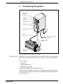
Introducing the System
5
1.1.
DDC 1.2 Servo Drive ........................................................................6
1.2.
Functional Performance Features ....................................................7
1.3.
Command Interface Card .................................................................8
1.4
Software Module ..............................................................................9
1.5.
Auxiliary Plug-In Cards ....................................................................9
1.6
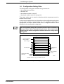
Configuration Rating Plate .............................................................10
2.
Technical Data / Ambient Conditions
2.1.
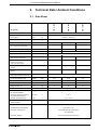
Data Sheet ..................................................................................... 11
2.2.
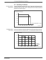
Operating Conditions .....................................................................12
3.
Electrical Connections -Installation Guidelines
3.1.
Terminal diagram ............................................................................14
3.2.
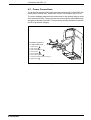
Power Connections ........................................................................15
3.3.
Grounding Conditions ....................................................................16
3.4.
Power Connection cross sections and Fuses ................................ 17
3.5.
Transformers .................................................................................. 19
3.6.
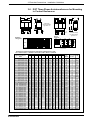
DST Three-Phase Autotransformers for Mounting in Control
Enclosures .....................................................................................20
3.7.
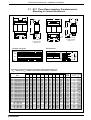
DLT Three-Phase Isolating Transformers for Mounting in
Control Enclosures .........................................................................21
3.8.
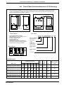
Three-Phase Autotransformers in IP 55 Housing ..........................22
3.9.
Motor Power Connection ...............................................................23
11
13
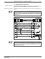
3.10. Motor Feedback Connection .......................................................... 27
3.11. Interface to NC Control Unit ...........................................................28
3.12. Control Circuit of the DDC Mains Contactor ..................................29
3.13. Control Circuit in the DDC with Dynamic Braking ..........................30
3.14. Control circuit of the DDC Mains Contactor Without Dynamic
Braking ........................................................................................... 32
3.15. Control Circuit of the DDC Mains Contactor with E-Stop Relays ..34
3.16. Control Inputs .................................................................................36
• DOK-DIAX02-DDC01******-PRJ1-EN-E1,44 • 01.97
3