1
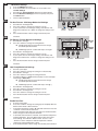
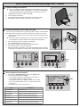
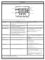
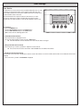
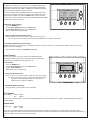
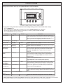
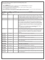
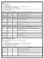
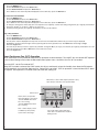
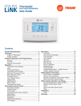
Thermostat 11-HD10D1-2 Installation and User Instructions ModelsAZEMT500BB32MAA The AZEMT500B Thermostat is compatible with single and multistage forced air systems, including: • Gas furnace systems • Oil furnace systems • Electric furnace systems • Heat pump systems • Air conditioning cooling systems The AZEMT500B Thermostat may be compatible with some other system types, including: • Boiler systems • Geothermal systems • Multi-zoned systems The AZEMT500B Thermostat is not compatible with the following system types: • Radiant floor systems • Wall heating systems • Proprietary HVAC Communication Protocols Schlage LiNK™ Customer Service: (877) 288-7707 • 240 V Electric baseboard heating systems ÎÎ NOTE: A 24 Volt common and hot wire MUST be connected to the AZEMT500B for operation. ÎÎ The AZEMT500B Thermostat is compatible with dual fuel systems (gas or oil furnace & heat pump combined) without adding a dual fuel accessory relay kit. Contents Physical Installation and Wiring........................................................................................................................................2 Field Wiring Diagrams ......................................................................................................................................................4 Enhanced Dehumidification Mode....................................................................................................................................7 Optional Remote Temperature Sensors Installation .........................................................................................................8 System Settings at Thermostat.......................................................................................................................................10 Perform System Checkout..............................................................................................................................................12 Enroll Thermostat into Schlage LiNK™ System..............................................................................................................13 Product Specifications....................................................................................................................................................14 Operation........................................................................................................................................................................15 Menu Maps.....................................................................................................................................................................16 User Settings..................................................................................................................................................................18 Installer Settings.............................................................................................................................................................22 Dehumidification Options Settings..................................................................................................................................24 Dual Fuel Settings...........................................................................................................................................................24 Schedules.......................................................................................................................................................................25 Limited Warranty.............................................................................................................................................................27 Physical Installation and Wiring 1 WARNING Voltage hazard. Can cause electrical shock or equipment damage. Disconnect power to heating and cooling equipment before beginning installation. 2 Remove the existing thermostat cover from the wall plate. Leave wires attached. MERCURY NOTICE When this control is replacing an old control that contains mercury in a sealed tube, do not dispose of your old control in the trash. Dispose of properly. Contact your local waste management authority for instructions regarding recycling and proper disposal of the old control. A listing of heating, ventilating and air conditioning wholesalers that participate in the Thermostat Recycling Corporation’s recycling program are available at www.thermostat-recyle.org. 2 The look of the existing thermostat may vary Thermostat cover Wall plate 3 Remove existing wall plate. ÎÎ Note: During this process, make sure that the wires do not pull back into wall opening. a. Detach all wires from wall plate. b. Remove all screws attaching the wall plate to the wall and remove wall plate. ÎÎ See Mercury Notice on page . . Wall plate 4 Separate the face of the new thermostat from the wall plate. Apply pressure at two tabs on top of wall plate to release it. 24R ÎÎ NOTE: It is not recommended that this Z-waveTM thermostat be mounted onto metal structures. Metal may adversely affect the radio frequency (RF) communication between the thermostat and the Z-waveTM bridge. 5 Y1 Y2 2 2 ld HC 24C 24R H W1 W2 /O RS 1 RS 2 Sh ld H1 Mark two mounting holes using new wall plate. c. d. e. f. g. 6 C G RS RS Sh Pull wires through hole in center of wall plate. Locate the new wall plate over existing opening. Mark two holes with pencil. Use a level to verify that the two hole locations are level. Correct hole locations as needed. 24 G RC Y1 24 C 24 RH W1 W2/O RS 1 RS 2 Sh ld H1 Y2 RS 2 RS Sh 2 ld HC Prepare two mounting holes. h. Drill 1/16” pilot holes in the two locations that were marked in step 9. If mounting to drywall with no studs behind it, enlarge pilot holes to 1/8” for anchors (included with the thermostat). i. If using anchors, screw them into the holes. Anchors 7 Install new wall plate. c. Pull wires through hole in center of wall plate. d. Locate the new wall plate over existing opening. e. Attach wall plate to wall using two screws provided. Do not overtighten. 24 G RC Y1 Y2 RS 2 RS Sh 2 ld HC 8 24 C 24 RH W1 W2/ O RS 1 RS 2 Sh ld H1 Attach all wires securely to the new thermostat. (See the Field Wiring Diagrams on the following page.) Note: A wire must be connected to “24COM” to power the thermostat. a. Use the information from the Field Wiring Diagrams to match the wires to the correct terminals. b. Use 1/8” blade screwdriver to secure wires in terminals. 24 G RC Y1 Y2 RS 2 RS 2 Sh ld HC 24 C 24 RH W1 W2 /O RS 1 RS 2 Sh CAUTION: EQUIPMENT DAMAGE HAZARD Improper wiring can lead to equipment damage. Follow the Terminal Connection information from step 6 carefully to ensure the control is wired properly. After wires are secure, bare wires MUST NOT touch each other. See the Field Connection Wiring Diagrams on the following pages for specific system applications. 3 ld H1 Field Wiring Diagrams The following table can be used to find the correct field connection wiring diagram for the HVAC System Type that is being installed. Indoor Unit Outdoor Unit 1 Stage Cooling 2 Stage Cooling 2 Step Cooling 1 Stage Heat Pump 2 Stage Heat Pump 2 Step Heat Pump 1 or 2 Stage Gas Furnace (PSC/CTM) A NA NA C1 NA NA 2 Stage VSPD Gas Furnace A A B C1 C1 D1 COM Furnace A A A C1 C1 C1 Air Handler (PSC/CTM) A NA NA C NA NA VSPD Air Handler A A B C C D COM Air Handler A A A C C C Oil Furnace (PSC) E NA NA E1 NA NA Oil Furnace (VSPD) E E F E1 E1 F1 Enhanced Dehumidification Mode See Notes 3, 4 1 For heat pumps matched with furnace, Dual Fuel must be enabled in the Mechanical Settings menu. 2 BAYSEN01ATEMPA is required for “restricted” mode of operation. See Remote Temperature Sensor Installation. 3 Enhanced Dehumidification Mode is not applicable with 2 Step outdoor products combined with legacy variable speed indoor products that use BK for high stage airflow: System types B, D, or F. 4 Smart Continuous Fan and Cooling Droop are available for all models. System Type A - 1 or 2 Stage Heating with 1 or 2 Stage Cooling (Note 6) Thermostat Connection Outdoor Unit Gas Furnace or Air Handler 24VAC Common B 24VAC Common B/C 24VAC Return R 24VAC Return R (Note 5) Heat Stage 1 W1 BLUE 24RC RED G Fan WHITE (Note 1) Heat Stage 2 W2 Fan G Compressor Stage 1 Y1 Compressor Stage 1 Y1 Compressor Stage 2 Y2 Compressor Stage 2 Y2 (Note 2) (Note 3, Note 4) YELLOW BROWN Remote Sensor 2 24C 24RH Y1 Comp W1 HEAT Y2 Comp W2/O RS2 RS1 RS2 RS1 Sensor Shield HC Sensor Shield H1 E G AN R O BK GREEN JP1: Internal RC to RH jumper Note 1 - May be W or W1. For systems with more than one W terminal, a field installed jumper may be required for W1 to W2 and W3. Note 2 - May be Y, Y1, or YLO Note 3 - May be Y or Y2 Note 4 - Y2 only found on variable speed furnace or air handler Note 5 - R required for 2 stage cooling unit Note 6 - For 2 Stage Cooling, outdoor unit contains two compressors Note 7 - Remote sensor wiring is not polarized. Note 8 - JP1 is an internal RC to RH jumper 4 Remote Temperature Sensor Connections and Operation: Indoor sensor connected to RS1. Replaces internal sensor. RS2 not connected. Indoor sensor connected to RS2. Averages temperature with internal sensor. RS1 not connected. Indoor sensors connected to RS1 and RS2. Averages RS1 and RS2 sensor temperatures. Internal sensor is not used. Outdoor sensor connected to RS2. Reports outdoor temperature to comfort control. Indoor sensor connected to RS1 and outdoor sensor connected to RS2. RS1 replaces the internal sensor. RS2 reports the outdoor temperature to comfort control. Remote Sensor 1 System Type B - 2 Stage Variable Speed Gas Furnace or Variable Speed Air Handler with 2 Step Cooling (Note 3, Note 4) Thermostat Connection Gas Furnace or Air Handler Outdoor Unit 24VAC Common B 24VAC Common B/C 24VAC Return R 24VAC Return R Heat Stage 1 W1 (Note 7) Heat Stage 2 W2 BLUE RED GREEN Compressor Stage 2 Y2 YELLOW YLO Remote Sensor 2 BROWN Compressor Stage 1 Y O (Note 1) (Note 2) Note 1 - Field installed jumper from R to O. Note 2 - Cut/remove R to BK jumper Note 3 - For non-communicating variable speed air handler. (For communicating air handler, use system type A diagram.) Note 4 - For 2 Step Cooling, outdoor unit contains one 2 stage scroll compressor Note 5 - JP1 is an internal RC to RH jumper Note 6 - Remote sensor wiring is not polarized. Note 7 - May be W or W1. For systems with more than one W terminal, a field installed jumper is required for W1 to W2 and W3. 24C 24RH Y1 Comp W1 HEAT Y2 Comp W2/O RS2 RS1 RS2 RS1 Sensor Shield Remote Sensor 1 Sensor Shield HC E G AN R O Compressor Stage 2 BK JP1: Internal RC to RH jumper (Note 5) G Fan WHITE Fan G Compressor Stage 1 Y1 24RC H1 Remote Temperature Sensor Connections and Operation: Indoor sensor connected to RS1. Replaces internal sensor. RS2 not connected. Indoor sensor connected to RS2. Averages temperature with internal sensor. RS1 not connected. Indoor sensors connected to RS1 and RS2. Averages RS1 and RS2 sensor temperatures. Internal sensor is not used. Outdoor sensor connected to RS2. Reports outdoor temperature to comfort control. Indoor sensor connected to RS1 and outdoor sensor connected to RS2. RS1 replaces the internal sensor. RS2 reports the outdoor temperature to comfort control. System Type C - PSC, CTM, Variable Speed, or 24 Volt Communicating Air Handler or gas furnace with 1 or 2 Stage/Step Heat Pump (Note 4, Note 5, Note 6, Note 7, Note 9) Thermostat Connection Air Handler or Gas Furnace Outdoor Unit 24VAC Common B 24VAC Common B/C 24VAC Return R 24VAC Return R X2 Heat Stage 1 W1 O O BLUE 24RC RED G Fan WHITE (Note 1) Fan G Compressor Stage 1 Y1 Compressor Stage 1 Y1 Compressor Stage 2 Y2 Compressor Stage 2 Y2 (Note 2) (Note 3) YELLOW Remote Sensor 2 BROWN (Note 8) 24C 24RH Y1 Comp W1 HEAT Y2 Comp W2/O RS2 RS1 RS2 RS1 Sensor Shield HC Sensor Shield H1 E G AN R O BK GREEN JP1: Internal RC to RH jumper Note 1 - May be W or W1. For systems with more than one W terminal, a field installed jumper may be required for W1 to W2 and W3. Note 2 - May be Y, Y1, or YLO Note 3 - May be Y or Y2 Note 4 - Applies to 2 step heat pumps matched with communicating air handler or furnace only. All other variable speed air handlers use system type D diagram. Note 5 - For 2 Stage, outdoor unit contains two compressors Note 6 - For 2 Step, outdoor unit contains one 2 stage scroll compressor Note 7 - PSC CTM air handler or gas furnace for single stage heat pump only Note 8 - Remote sensor wiring is not polarized. Note 9 - For heat pumps matched with furnace, dual fuel must be enabled in the “Mechanical Settings” menu. BAYSEN01ATEMPA required for “restricted” mode of operation. See “Remote Temperature Sensor Installation”. 5 Remote Temperature Sensor Connections and Operation: Indoor sensor connected to RS1. Replaces internal sensor. RS2 not connected. Indoor sensor connected to RS2. Averages temperature with internal sensor. RS1 not connected. Indoor sensors connected to RS1 and RS2. Averages RS1 and RS2 sensor temperatures. Internal sensor is not used. Outdoor sensor connected to RS2. Reports outdoor temperature to comfort control. Indoor sensor connected to RS1 and outdoor sensor connected to RS2. RS1 replaces the internal sensor. RS2 reports the outdoor temperature to comfort control. Remote Sensor 1 (Note 8) System Type D - Variable Speed Air Handler or Furnace with 2 Step Heat Pump Note 3 Thermostat Connection Air Handler or Gas Furnace Outdoor Unit 24VAC Common B 24VAC Return R 24VAC Return R X2 Heat Stage 1 W1 O BLUE 24VAC Common B/C (Note 1) 24RC RED O GREEN Compressor Stage 1 Y1 Y1 Compressor Stage 2 Y2 Compressor Stage 1 Y2 Remote Sensor 2 YELLOW BROWN (Note 4) W1 HEAT Y2 Comp W2/O RS2 RS1 RS2 RS1 Sensor Shield Sensor Shield Remote Sensor 1 (Note 4) H1 E G AN R (Note 2) Y1 Comp HC O Compressor Stage 2 BK 24C 24RH G Fan WHITE Fan G JP1: Internal RC to RH jumper Note 1 - Field installed jumper from R to O Note 2 - Remove R to BK jumper Note 3 - For 2 Step Heat Pump, outdoor unit contains one 2 stage scroll compressor Note 4 - Remote sensor wiring is not polarized Note 5 - For Heat Pumps matched with furnace, dual fuel must be enabled in the “Mechanical Settings” menu. BAYSEN01ATEMPA required for “restricted” mode of operation. See “Remote Temperature Sensor Installation”. Remote Temperature Sensor Connections and Operation: Indoor sensor connected to RS1. Replaces internal sensor. RS2 not connected. Indoor sensor connected to RS2. Averages temperature with internal sensor. RS1 not connected. Indoor sensors connected to RS1 and RS2. Averages RS1 and RS2 sensor temperatures. Internal sensor is not used. Outdoor sensor connected to RS2. Reports outdoor temperature to comfort control. Indoor sensor connected to RS1 and outdoor sensor connected to RS2. RS1 replaces the internal sensor. RS2 reports the outdoor temperature to comfort control. System Type E - Oil Furnace with 1 or 2 Stage Cooling or Heat Pump R1 (Isolation relay, See R1 below) (Note 7) Thermostat Connection Oil FurnacePSC or Variable speed Outdoor Unit 24VAC Common B 24VAC Common B/C 24VAC Return R 24VAC Return R (Note 4) X2 O (Note 3) Heat Stage 1 W1 BLUE 24RC RED G Fan WHITE (Note 1) O GREEN Fan G Compressor Stage 1 Y1 Compressor Stage 1 Y1 Compressor Stage 2 Y2 Compressor Stage 2 Y2 YELLOW (Note 1) (Note 2, Note 5) BROWN (Note 9) 24C 24RH Y1 Comp W1 HEAT Y2 Comp W2/O RS2 RS1 RS2 RS1 Sensor Shield HC Sensor Shield Remote Sensor 1 (Note 9) H1 E G AN R (Note 3) O BK Remote Sensor 2 JP1: Internal RC to RH jumper Note 1 - May be Y, Y1, or YLO Note 2 - May be Y or Y2 Note 3 - For variable speed oil furnaces, factory installed jumpers R to O and R to BK Note 4 - R to ODU required for 2 stage cooling models Note 5 - Variable speed furnace required for 2 stage cooling Note 6 - Field supplied Isolation Relay Note 7 - For 2 Stage, outdoor unit contains two compressors Note 8 - For Heat Pumps matched with oil furnaces, dual fuel must be enabled in the “Mechanical Settings” menu. BAYSEN01ATEMPA required for “restricted” mode of operation. See “Remote Temperature Sensor Installation”. Note 9 - Remote sensor wiring is not polarized 6 OIL BURNER PRIMARY R1 (Note 6) Remote Temperature Sensor Connections and Operation: Indoor sensor connected to RS1. Replaces internal sensor. RS2 not connected. Indoor sensor connected to RS2. Averages temperature with internal sensor. RS1 not connected. Indoor sensors connected to RS1 and RS2. Averages RS1 and RS2 sensor temperatures. Internal sensor is not used. Outdoor sensor connected to RS2. Reports outdoor temperature to comfort control. Indoor sensor connected to RS1 and outdoor sensor connected to RS2. RS1 replaces the internal sensor. RS2 reports the outdoor temperature to comfort control. System Type F - Variable Speed Oil Furnace with 2 Step Cooling or Heat Pump R1 (Isolation relay, See R1 below) (Note 6) Thermostat Connection Oil Furnace- Variable speed Outdoor Unit 24VAC Common B 24VAC Common C 24VAC Return R 24VAC Return R (Note 4) X2 BLUE 24RC RED (Note 3) (Note 1) O O GREEN Fan G Compressor Stage 1 Y1 YLO Compressor Stage 2 Y2 Compressor Stage 1 Y Remote Sensor 2 YELLOW BROWN (Note 8) (Note 1) (Note 2) R (Note 3) (Note 4) Y1 Comp W1 HEAT Y2 Comp W2/O RS2 RS1 RS2 RS1 Sensor Shield Sensor Shield HC O Compressor Stage 2 BK 24C 24RH G Fan WHITE Heat Stage 1 W1 JP1: Internal RC to RH jumper Remote Sensor 1 (Note 8) H1 AN G E Note 1 - May be Y, Y1, or YLO Note 2 - May be Y or Y2 Note 3 - Factory installed jumpers R to O and R to BK Note 4 - Cut / remove R to BK jumper for 2 step compressors Note 5 - Field supplied Isolation Relay Note 6 - For 2 Step, outdoor unit contains one 2 stage scroll compressor Note 7 - For Heat Pumps matched with oil furnaces, dual fuel must be enabled in the “Mechanical Settings” menu. BAYSEN01ATEMPA required for “restricted” mode of operation. See “Remote Temperature Sensor Installation”. Note 8 - Remote sensor wiring is not polarized OIL BURNER PRIMARY R1 Remote Temperature Sensor Connections and Operation: Indoor sensor connected to RS1. Replaces internal sensor. RS2 not connected. Indoor sensor connected to RS2. Averages temperature with internal sensor. RS1 not connected. Indoor sensors connected to RS1 and RS2. Averages RS1 and RS2 sensor temperatures. Internal sensor is not used. Outdoor sensor connected to RS2. Reports outdoor temperature to comfort control. Indoor sensor connected to RS1 and outdoor sensor connected to RS2. RS1 replaces the internal sensor. RS2 reports the outdoor temperature to comfort control. (Note 5) Enhanced Dehumidification Mode Enhanced Dehumidification Mode When the AZEMT500B is connected to variable speed indoor products, the enhanced dehumidification mode can reduce indoor airflow to improve dehumidification during the cooling run cycle. When 24 VAC is present at the BK terminal, (HC to H1 = N.C.) airflow will be 100 percent. When 24 VAC is removed from BK, (HC to H1 = N.O.) airflow will be reduced by 20 percent. See Notes 11 and 12. Outdoor Unit HC to H1 = N.C. when RH% is lower than RH% setpoint HC to H1 = N.O. when RH% is higher than RH% setpoint Thermostat Connection Variable speed Gas Furnace or Air Handler 24VAC Common B 24VAC Common B/C 24VAC Return R 24VAC Return R (Note 5) Not applicable with 2 step outdoor products combined with legacy variable speed indoor products that require BK for high stage airflow: System Types B, D, or F on page 4. Heat Stage 1 W1 BLUE 24RC RED G Fan WHITE (Note 1) Heat Stage 2 W2 Fan G Compressor Stage 1 Y1 Compressor Stage 1 Y1 Compressor Stage 2 Y2 Compressor Stage 2 Y2 (Note 2) (Note 3, Note 4) GREEN YELLOW BLACK (Note 11, Note 12) 24C 24RH Y1 Comp W1 HEAT Y2 Comp W2/O Remote Sensor 2 RS2 RS1 RS2 RS1 Note 9 HC BROWN BK JP1: Internal RC to RH jumper Sensor Shield Sensor Shield H1 E G AN R O Note 1 - May be W or W1. For systems with more than one W terminal, a field installed jumper may be required for W1 to W2 and W3. Note 2 - May be Y, Y1, or YLO Note 3 - May be Y or Y2 Note 4 - Y2 only found on variable speed furnace or air handler Note 5 - R required for 2 stage unit Note 6 - For 2 Stage, outdoor unit contains two compressors Note 7 - for heat pumps matched with furnace, Dual Fuel must be enabled in the Mechanical Settings menu. BAYSEN01ATEMPA is required for “restricted” mode of operation. See Remote Temperature Sensor Installation. Note 8 - Remote sensor wiring is not polarized. Note 9 - Field installed jumper from R to HC Note 10 - JP1 is an internal RC to RH jumper Note 11 - Enhanced dehumidification must be enabled: See “Installer Settings” menu Note 12 - Installer must cut or remove the R to BK jumper on variable speed indoor unit 7 Remote Temperature Sensor Connections and Operation: Indoor sensor connected to RS1. Replaces internal sensor. RS2 not connected. Indoor sensor connected to RS2. Averages temperature with internal sensor. RS1 not connected. Indoor sensors connected to RS1 and RS2. Averages RS1 and RS2 sensor temperatures. Internal sensor is not used. Outdoor sensor connected to RS2. Reports outdoor temperature to comfort control. Indoor sensor connected to RS1 and outdoor sensor connected to RS2. RS1 replaces the internal sensor. RS2 reports the outdoor temperature to comfort control. Remote Sensor 1 Optional Remote Temperature Sensors Installation Wire specification (RS1 & RS2): 2 conductors, 18 gauge wire. Make sure that the sensor wires have a cable separate from the thermostat cable. Best results for distances of 100 feet or less. Accuracy may be affected for distances up to a maximum of 200 feet. Shielded cable is recommended for distances over 100 feet and less than 200 feet. CAUTION: Keep this wiring at least one foot away from large inductive loads such as electronic air cleaners, motors, line starters, lightning ballasts, and large distribution panels. Failure to follow these wiring practices may introduce electrical interference (noise) which can cause erratic system operation. Shielded cable is required if the above wiring guidelines cannot be met. Be sure to ground only one end of the shield to the thermostat common terminal. Tape back the other end of the shield. Remote Sensors Part Numbers Remote Indoor Sensor: Use ZZSENSAL0400AA for indoor applications. Remote Outdoor Sensor: Use BAYSEN01ATEMPA for outdoor applications. ÎÎ IMPORTANT: Make sure that the sensor wires have a cable separate from the thermostat cable. ÎÎ IMPORTANT: Follow directions below for averaging. These instructions replace the averaging information found in the Installer’s Guide for the ZZSENSAL0400AA. ÎÎ Note: Remote Sensor 2 can be selected as an indoor sensor or an outdoor sensor. Remote Temperature Sensor Connections and Operation: A) Indoor sensor connected to RS1. Replaces internal sensor. RS2 not connected. Remote Sensor 1 (RS1) replaces the internal temperature sensor of the thermostat. This allows the thermostat to be installed in a location different than the area where the temperature will be measured. Use ZZSENSAL0400AA. See Figure A. Figure A Remote Temp Sensor Black RS1 Red Sensor wiring is not polarized. B) Indoor sensor connected to RS2. Averages temperature with internal sensor. RS1 not connected. RS2 is used as an indoor temperature sensor that averages temperatures with the internal sensor. Use ZZSENSAL0400AA. See Figure B. If RS2 is set to indoor location (“IN” - Default selection in the thermostat installation set up menu) and a sensor is attached to the RS2 sensor terminals of the thermostat, the RS2 temperature is averaged with the thermostats internal temperature sensor. C) Indoor sensors connected to RS1 and RS2. Averages RS1 and RS2 sensor temperatures. Internal sensor is not used. Remote Sensor 1 (RS1) and Remote Sensor 2 (RS2) are both used as indoor sensors. The RS1 temperature and RS2 temperature is averaged. See Figure C. D) Outdoor sensor connected to RS2. Reports outdoor temperature to comfort control. RS2 is used as an outdoor temperature sensor. Use BAYSEN01ATEMPA. See Figure B. RS1 RS1 Sensor RS2 RS2 RS1 Figure B RS2 Remote Temp Sensor RS1 Black RS2 Red Sensor wiring is not polarized. RS2 Sensor RS2 Figure C Remote Temp Sensor Black RS1 Red RS1 Black RS2 Remote Temp Sensor RS2 Red RS2 RS1 Sensor RS2 Sensor Sensor wiring is not polarized. If RS2 is set to outdoor location (“OUT” in the thermostat installation set up menu) and a sensor is attached to the RS2 sensor terminals of the thermostat, the RS2 temperature is used to report outdoor temperature. It is also displayed on the thermostat main screen. See Step 15 to configure for outdoor temperature sensing. E) Indoor sensor connected to RS1 and Outdoor sensor connected to RS2. RS1 replaces the internal sensor. RS2 reads the outdoor temperature. Remote Sensor 1 (RS1) replaces the internal temperature sensor of the thermostat. This allows the thermostat to be installed in a location different than the area where the temperature will be measured. Use ZZSENSAL0400AA. RS2 is used as an outdoor temperature sensor. Use BAYSEN01ATEMPA. See Figure C. 8 If RS2 is set to outdoor location (“OUT” in the thermostat installation set up menu) and a sensor is attached to the RS2 sensor terminals of the thermostat, the RS2 temperature is used to report outdoor temperature. It is also displayed on the thermostat main screen. See Step 15 to configure for outdoor temperature sensing. 9 If necessary, cut the internal jumper wire (JP1). If only one wire is connected to either 24RC or 24RH as shown Do NOT cut JP1 jumper If wires are connected to both 24RC and 24RH as shown Cut JP1 jumper RC 24 G 24RC C Y1 H 4R Y2 2 RS 2 RS LD H S 24 2 W1 24RH /O W2 1 RS 1 RS D L SH 24RC W1 OR 1 JP ER MP T JU /RH CU RC LIT SP TO H1 HC 24RH W1 24RC 24RH W1 Cutting the JP1 jumper The jumper is located on back of the thermostat face as shown in the illustration to the right. Cut the jumper using small diagonal cutters being careful not to damage the board. 10 1 JP ER MP H T JU C/R CU IT R L SP TO 1 JP ER MP H T JU C/R CU IT R L SP TO Attach the thermostat face to the wall plate. a. Carefully align the face plate to the wall plate while aligning pins into wire terminals. b. Once thermostat face is properly aligned, apply pressure at top and bottom of thermostat face until it is secure. 24 G RC Y1 Y2 RS 2 RS Sh 2 ld HC 11 24 C 24 RH W1 W2 /O RS 1 RS 2 Sh ld H1 Turn power to heating and cooling system back on. The thermostat display should turn on and begin displaying information. If the thermostat display does not come on, go back through the installation steps and look for problems. 9 System Settings at Thermostat 12 Set Time and Date a. Press the Menu button twice. User Settings 11:15 AM 75 MENU MODE FAN Scroll up Set Clock Filter Service Maint Service Screen Timeout 76 H 74 C Select Done RUN Scroll down Select button MENU button b. Scroll up or down to User Settings (it is the first option), then press the Select button. Set Clock Press or to highlight the data you want to change. Scroll up or down (+ or -) to make changes. Press the Set button when you are finished. Press the Done button twice to exit the menu. Scroll up User Settings Usage Graph ESM Setpoints Z-Wave Install Done d. e. f. g. Set Scroll down Set Clock Time Date Day Back Scroll up 10 :15 AM 3 / 23 / 09 Mon Set Set button c. Scroll up or down to Set Clock (it is the first option), then press the Select button. 13 If your System Type is: • Gas Furnace - Single Stage, Perform System Checkout step 16 • Gas Furnace - Multistage, perform step 14 then step 14A • Electric Furnace, perform step 14 then step 14B • Heat Pump, perform step 14 then step 14C • Heat Pump Dual Fuel, perform step 14 then step 14D 10 Set button Scroll down 14 Mechanical Settings a. b. c. d. e. 14A 11:15 AM 75 MENU MODE FAN 76 H 74 C RUN For Gas Furnace - Multistage Mechanical Settings a. b. c. d. 14B Press the MENU button twice. Press and hold the two inner buttons for 3 seconds to view Installer Settings Scroll down to System Settings and press the Select button. Scroll to Mechanical Settings (it is the first option), then press the Select button. Choose option A-D below: Scroll down to 2nd Stage Heat. Press the + button to change the setting to Y for Yes. If your system also has 2nd stage cooling, scroll down to 2nd Stage Cool and Press the + button to change the setting to Y for Yes. Press the Done button 4 times and go to Perform System Menu button Two inner buttons Checkout. For Electric Furnace Mechanical Settings a. b. Scroll down to Fan Type. Press the + button to change the setting Electric. ÎÎ If Single Stage System, press Done 4 times and go to Perform System Checkout. Mechanical Settings Scroll up Type Heatpump Fan Type Elec C/O Type w/Cool 2nd Stage Heat N Select Done ÎÎ If Multistage System, continue with steps c through f. c. d. e. f. 14C Scroll down to 2nd Stage Heat. Press the + button to change the setting to Y for Yes. If your system also has 2nd stage cooling, scroll down to 2nd Stage Cool and Press the + button to change the setting to Y for Yes. Press the Done button 4 times and go to Perform System Checkout. Heat Pump Mechanical Settings a. b. c. d. e. Scroll to system Type. Press the + button to change the setting to Y to Heat Pump. Scroll down to Fan Type. Press the + button to change the setting to Electric. If Coleman, Rheem, or Rudd brand heat pump, scroll to C/O Type and change to With Heat. ÎÎ If Single Stage System, press Done 4 times and go to Perform System Checkout. f. g. h. i. j. Scroll down to 2nd Stage Heat. Press the + button to change the setting to Y for Yes. Scroll down to 2nd Stage Cool. Press the + button to change the setting to Y for Yes. Press the Done button 4 times and go to Perform System ÎÎ If Multistage System, continue with steps f through j. 14D Checkout. Enable Dual Fuel a. b. c. d. e. f. 11 Scroll to system Type. Press the + button to change the setting type to Heatpump DF. The default control mode is Non-restricted. To change to Restricted, scroll to DF Type Non-restricted. Press the + button to set the mode to Restricted. If Non-restricted control mode was selected, press the Done button 4 times and go to Perform System Checkout. If restricted control mode was selected, set the desired compressor lockout temperature. Press the Done button 3 times then select User Settings. Scroll down to Balance Point. Use the + and - buttons to set the compressor lockout temperature. Default compressor lockout temperature is 40°F. Press the Done button 2 times and go to Perform System Checkout. + button Select button Scroll down 15 Optional Remote Temperature Sensors Installation Remote sensor input RS2 can be configured for use as indoor or outdoor temperature sensing. An outdoor temperature sensor is required for Dual Fuel Restricted mode. The factory default setting for RS2 is “IN” for use with remote indoor temperature sensing and/or averaging. To configure RS2 to sense outdoor temperature, complete the following steps: a. b. c. d. e. f. Press the MENU button twice to access the Menu Selection screen. From the Menu Selection screen, press and hold the two inner buttons down for 4 seconds to reach the Installer Settings menu. From the Installer Settings screen, scroll down to Remote Sensors using the Scroll down button and press the Select button. From the Remote Sensors screen, select the option for RS2 remote senor location. (IN is the factory default setting) To change RS2 for use as an outdoor temperature sensor, press the + button to change this setting to OUT. Press the Done button three times to return to the home screen. Remote Sensors RS2 Location DONE Press DONE button to exit back to installer settings screen. + IN - Press the +/- buttons to change the setting. Perform System Checkout 16 Test All Modes of Operation Fan, Cooling, and Heating. 12 Enroll Thermostat into existing Schlage LiNK™ System 17 Prepare the bridge for enrollment. ÎÎ Note: If the bridge is already installed, follow the instructions as they are written in the following steps. If the bridge is not installed, follow the Quick Start Guide publication number shipped with the thermostat starter kit. a. b. c. d. Blue light Unplug Ethernet and power cables from bridge. Install a quality 9 volt battery. Verify that blue light is blinking. If blue light is solid, battery is dead. Take bridge to the location where the thermostat is mounted. Battery 18 Enroll the thermostat into the bridge. (Inclusion) If you are using a controller that is not a Schlage LiNKTM bridge, consult the Quick Start Guide that came with the controller to find out how to enroll a new device. a. Hold the bridge within 6 feet (1.8 meters) of the thermostat throughout steps “b” through “f”. ÎÎ After you begin the enrollment process, you have 30 seconds to complete the remainder of the steps. Study the steps below before beginning. b. c. d. e. f. 24 Press and release the plus (+) button on the bridge. Press the MENU button on the thermostat. Scroll down to Z Wave Install, and press the Select button. Press the Yes button to enroll the thermostat. Observe the lights on the bridge. The orange light will blink while enrollment is taking place. Enrollment is complete when the orange light becomes solid. 76 H 75 MENU MODE Y2 2 2 ld H1 24 C 24 RH W1 W2/ O RS 1 RS 2 Sh ld H2 y wa e t a G 74 C FAN RUN User Settings Usage Graph ESM Setpoints ZWave Install Select Done MENU button Scroll down Select button Verify enrollment of the thermostat. a. Scroll down to Thermostat Info, and press the Select button. b. Look at the number listed after ZNID. • If the number listed there is anything other than “000”, the thermostat has been successfully enrolled. • If the number listed there is “000”, the thermostat has NOT been successfully enrolled. In this case, repeat step 22 and verify again. c. Press Done button 2 times when finished. Item 13 RC Y1 RS RS Sh Menu Selection 11:15 AM 19 G “+” Button Description AZEMT500BB32 Model Number Ver: 01.00.13 Firmware version (number may vary) ZVER: 02.00.9 Z-Wave version (number may vary) ZNID: 013 Z-Wave node ID (number may vary) ZHID: 01.07.37.a7 Z-Wave Home ID (number may vary) System Type: Standard System type may be Standard or Heat Pump Fan Type: Gas Fan type may be Gas or Elect (electric) Thermostat Info AZEMT500BB32 Ver: 01.00.13 ZVER:02.00.0 ZNID: 013 ZHID: 01.07.37.a7 System Type: Standard Fan Type: Gas Done ZNID 20 Establish Online Control of the Thermostat. Schlage LiNK account must be active before continuing. See link.schlage.com for more information. a. b. c. d. Remove the battery from the bridge. Plug the Ethernet and power cord back into the bridge. Log into your account at www.schlagelink.com Click the Climate tab and follow the on screen instructions. Exclusion (Only used to unenroll a thermostat from the bridge) a. Install a new, high-quality 9-volt battery into the bridge. b. Hold the bridge within 6 feet (1.8 meters) of the thermostat throughout the entire exclusion process. ÎÎ After you begin the exclusion process, you have 30 seconds to complete the remainder of the steps. Study the steps below before beginning. c. d. e. f. g. Press and release the minus (-) button on the bridge. Press the MENU button on the thermostat. Scroll down to Z-Wave Install and press the Select button. Press the Yes button to exclude the thermostat. Observe the lights on the bridge. The orange light will blink while exclusion is taking place. Exclusion is complete when the orange light becomes solid. ÎÎ Z-Wave™ controllers from various manufacturers may support the Z-Wave™ Thermostat General V2 Device class used by the Z-Wave™ Thermostat. If you are using a controller that is not a Schlage bridge, consult the instructions that came with the controller to find out how to enroll a new device. Product Specifications Specification Description Product Model: AZEMT500BB32MAA Product: Thermostat for Heating and Cooling HVAC System control. Z-Wave™ RF communications enabled Size: 5.7” wide x 4.0” height x 1.2” depth Display: Graphical LCD, 2.75” x 1.5”, 64x128-pixel Backlight: Yes, Blue/white, Controllable, on, off, timeout Contrast: Adjustable on screen Buttons: 6 Power: 24VAC from HVAC System HVAC System Type Compatible: Standard (gas/electric), Heat Pump. or Dual Fuel Multistage System Compatible: Standard HVAC Systems: 2 stage heating, 2-stage cooling, dual fuel Heat Pump Systems: 3 stage heating (2-compressor, 1 aux heat), 2-stage cooling 14 Heat Pump change over valve: Selectable change over with cool or with heat Communications: Z-Wave™ RF Memory: Non-volatile Clock: 24 hour back-up power provided by super capacitor Operation The model AZEMT500BB32MAA thermostat provides typical thermostat control of a central heating and cooling HVAC system. These thermostats also features a Z-Wave™ module for remote control. Clock Display Tempurature Display 11:15 AM Sys Off Run Filter MENU 72 AUTO MODE AUTO FAN Setpoint Up/Down Buttons 77 H 74 C RUN Dynamic Labels Setpoint Display Menu Button System Mode Button Fan Mode Button Schedule Mode Button Normally, the thermostat displays the thermostat control screen as shown above. Item Description Notes See Set Clock for more information. Clock Display The current time is displayed in the upper left corner of the main screen. The time will blink when the clock has not been set. Dynamic Labels and Function Control Buttons The buttons are defined by the dynamic labels above each button. As you navigate through menus, the labels for the buttons will change. Setpoint Display and Setpoint Up/Down Buttons The current heat and cool setpoints are displayed. These setpoints may be set using the Z-Wave control system, the thermostat’s internal schedule, or by pressing the Setpoint Up/Down buttons. In HEAT mode, the Setpoint Up/Down buttons change the heat setpoint. In COOL mode, they change the cooling setpoint. In AUTO mode, the buttons change the last call’s heating or cooling setpoint. The setpoints will push each other if they are adjusted to within the minimum heat/cool separation setting. This is normally 3 degrees. Temperature Display The thermostat displays the current temperature as sensed by the internal temperature sensor. The internal temperature sensor can be adjusted as necessary. See Internal Sensor Calibration for more information. Menu Button Button used to access other thermostat menus Other thermostat menus can be accessed by pressing the MENU button. System Mode Button Button used to change the system mode Off: System off The internal schedule is disabled by default. See Schedules for more information. Heating: Heating only on Cooling: Cooling only on Auto: Heating/Cooling on as necessary Fan Mode Button Button used to change the fan mode: Auto: Fan on when cooling/heating is necessary On: Fan constantly on Fan Cycler (note 1) Smart Continuous Fan (notes 1, 2) Schedule Mode Button Button used to change the schedule mode: Hold: System maintains the current temperature setpoints. Schedules are disregarded. Run: Run the system schedule (or Z-Wave controlled schedule) Energy Saving Mode: Temperature setpoints in ESM Setpoints are maintained. See ESM Setpoints on for more information. Note 1 See the Installer Settings menu to enable Note 2 See the User Settings menu to set RH setpoint 15 Minimized Display Mode Optionally, you can set the thermostat to show only the temperature in minimized display mode. This mode can be enabled or disabled in the Users Settings screen. ÎÎ See Screen Timeout for more information. 72 Menu Maps - User Settings User settings are accessed by pressing the MENU button on the main screen. Schedule (if enabled) Note 1 Optional Menus (enabled in the Installers Settings menu) Schedules (Disabled by Default) Heat and Cool User Settings Schedule Set Clock Copy Filter Service Maint Service Preset: Comfort Screen Timeout Preset: Energy Save RH% Setpoint Balance Point - Note 2 F/C Settings F/C Mode Sensor Calibration Internal Remote 1 Remote 2 Outside Backlite/Display Backlite Timeout ON Level OFF Level Contrast Usage Graph Heat/Cool ESM Setpoints ESM - Heat ESM - Cool Zwave Install Thermostat Info 16 Select Menu Select Button Done Back one level or to exit Current selection on thermostat Note 1 - Only visible if Schedule Enable is selected in the Installer Settings menu. Disabled by default Note 2 - Only visible if Dual Fuel Restricted is selected in Mechanical Settings menu. Menu Maps - Installer Settings Installer settings are accessed by pressing the MENU button on the main screen then pressing and holding the two middle buttons until the Installer Settings appear. C Delta Stg2 ON C Delta Stg2 OFF Max Heat SP Installer Settings (Hidden) Display Lock Max Cool SP System Settings Min Run Time Min Off Time Mechanical Settings T-Sense Match Type Gas/Elec Fan Cycler Fan ON Time Fan Type Gas Elec Fan OFF Time Remote Sensors RS2 Location 2nd Stage Heat Dehumid Options 2nd Stage Cool Cooling Droop Smart Cont Fan Type Heatpump RH Calibration C/O Type w/Heat w/Cool 2nd Stage Heat Aux Heat (HP) 2nd Stage Cool Type Heatpump DF DF Type Unrestrict Restrict C/O Type w/Heat w/Cool 2nd Stage Heat Aux Heat (HP) 2nd Stage Cool Balance Point (if DF = Restrict) Sched Enable Recovery Enable H/C Delta H Delta Stg1 ON H Delta Stg1 OFF H Delta Stg2 ON H Delta Stg2 OFF H Delta Stg3 ON H Delta Stg3 OFF C Delta Stg1 ON C Delta Stg2 OFF 17 Enhanced Dehumid Restore Defaults User Settings Filter Service The Filter Service screen will show the accumulated Runtime hours as well as the Service Interval that will be used to trigger a Filter Message. Any type of HVAC operation that causes the HVAC system fan to run will cause the Filter Runtime value to increase. When the Runtime hours equals the Service Interval hours, a “Filter” message to remind you to replace the filter. Once the filter has been replaced, press the Reset button to reset the Filter Runtime value to zero. Filter Service Filter Runtime Service Interval Done + 184 HRS 300 HRS - Reset Filter Settings 1. Press the MENU button. 2. Scroll to User Settings and press the Select button. 3. Scroll to Filter Service and press the Select button. 4. Make choice from the following options A-C: A. To View/Reset Filter Runtime 5. The Filter Runtime is displayed in hours. 6. To reset the Filter Runtime counter, press the Reset button. ÎÎ The Filter Runtime counter should be reset each time the filter is changed. B. Change the Filter Service Interval 7. Press the plus (+) or minus (-) buttons to adjust the service interval. ÎÎ The service interval can be set between 100 and 4000 hours in 100 hour increments. C. Disable the Filter Service Interval When the filter service interval is disabled, the runtime counter will continue to count the runtime, but the filter service indicator will never be displayed.. 8. Press the minus (-) button until Disabled is displayed 18 Maintenance Service The Maintenance Service screen shows the accumulated Heat and Cool Runtime hours as well as the Service Interval that will be used to trigger a Maintenance Message. Any HEAT or COOL type of HVAC operation will cause the respective Runtime values to increase. When the combined HEAT and COOL Runtime hours equals the Service Interval hours, a “Maint” message to remind you your HVAC system may require periodic maintenance. Press the Menu button to enter the Filter Service screen. The Reset button can be pressed and the HEAT and COOL Runtime values will be reset to zero. Maintenance Service Heat Runtime Cool Runtime 200 HRS 300 HRS Service Interval Done 3000HRS + - Reset Maintenance Service Interval 1. Press the MENU button. 2. Scroll to User Settings and press the Select button. 3. Scroll to Maint Service and press the Select button. 4. Make a choice from the options A-B A. Change the Maintenance Service Interval 5. Press the plus (+) or minus (-) buttons to adjust the service interval. ÎÎ The service interval can be set between 200 and 4000 hours in 100 hour increments. B. Disable the Maintenance Service Interval When the maintenance service interval is disabled, the runtime counter will continue to count the runtime, but the maintenance service indicator will never be displayed. 6. Press the minus (-) button until Disabled is displayed Screen Timeout This is the time before any screen reverts to the Minimized Screen (temperature display only), after you stop pushing buttons. Minimized Screen feature is disabled by setting this time to “0”. Screen Timeout 1. 2. 3. 4. Press the MENU button. Scroll to User Settings and press the Select button. Scroll to Screen Timeout Make choice from the options A-B. User Settings Set Clock Filter Service Maint Service Screen Timeout Done 0 Select A. Change the Screen Timeout 5. Press the plus (+) or minus (-) buttons to adjust the time (in seconds). ÎÎ The screen time-out can be set between 0 and 120 seconds. Zero (0) is the default setting. When set to Zero (0), the minimized screen feature is disabled. B. Disable the Minimized Display 6. Press the minus (-) button until zero (0) is displayed. RH% Setpoint RH% Setpoint Default Range 50% 40-70% This is a user selectable value for when enhanced dehumidification or smart continuous fan is enabled. See Dehumidification options in Installer Settings. Balance Point Balance Point Default Range 40 F 5-70 F This is a user selectable value for when dual fuel “Restricted” mode is enabled. The temperature selected is the compressor lockout temperature. When the outdoor temperature is above this setpoint, only the heat pump will run for heating. When the outdoor temperature is below this setpoint, only the furnace will run for heating. 19 F/C Settings The F/C Settings screen is use to select the temperature display mode. Fahrenheit (F) or Celsius (C) are the two available modes. F/C Settings Change the Temperature Mode 1. Press the MENU button. 2. Scroll to User Settings and press the Select button. 3. Scroll to F/C Settings and press the Select button. 4. Press the plus (+) or minus (-) buttons to change the temperature mode. Select F for Fahrenheit or C for Celsius. F/C Mode Done F + - Internal Sensor Calibration The Sensor Calibration screen is used to change the temperature calibration of the internal temperature sensor. The temperature calibration can be changed by +/- 7 degrees. When the Sensor Calibration screen is selected, the current temperature calibration is displayed. In the example screen, the calibrated temperature is 77 and the number of degrees of offset being applied is 1. Sensor Calibration Internal (77) Change the Sensor Calibration 1. Press the MENU button. 2. Scroll to User Settings and press the Select button. 3. Scroll to Sensor Calibration and press the Select button. 4. Press the plus (+) or minus (-) buttons to change the sensor calibration. ÎÎ After this screen is closed, it may take a few seconds for the temperature displayed on the main thermostat screen to update to the new temperature. Done + 1 - Usage Graph The Usage Graph shows daily heating and cooling runtime hours for a week. The button in the lower right corner will change depending on what is being displayed. When the heating time is displayed, the button will read Cool. When the cooling time is displayed, the button will read Heat Press the Heat/Cool button to display the heating/cooling time. 20 15 10 Heating time (Hrs) 5 Sun Mon Tue Wed Thu Fri Sat Done Cool 20 Backlite/Display The Backlite/Display screen is used to set the backlight time-out and contrast. Backlite Timeout is the time (in seconds) from the last button press to the backlight going out. The time-out can be set between zero (0) and one hundred and twenty (120) seconds. Thirty (30) is the default setting. When set to zero (0), the backlight will remain always on. Contrast sets the contrast level of the LCD display. The contrast can be set between zero (0) and twenty (20). Ten (10) is the default setting. If the display is too light, using a higher number. If dark lines appear in the display, use a lower number. Backlite/Display Backlite Timeout Contrast Done 60 + 10 - Backlight 1. Press the MENU button. 2. Scroll to User Settings and press the Select button. 3. Scroll to Backlite/Display and press the Select button. 4. Make choice from the options A-B. A. Adjust the Backlight 5. Scroll to Backlite Timeout. 6. Press the plus (+) or minus (-) buttons to change the number of seconds. ÎÎ The backlight time-out can be set between 0 and 120 seconds. Thirty (30) is the default setting. When set to Zero (0), the backlight will remain always on. B. Adjust the Contrast 7. Scroll to Contrast. 8. Press the plus (+) or minus (-) buttons to change the contrast value. ÎÎ The contrast can be set between 0 and 20. Ten (10) is the default setting. ESM Setpoints Energy Saving Mode (ESM) Setpoints are the setpoints used when the Energy Saving Mode schedule is selected in the Schedule Mode screen. Energy Saving Mode Setpoings Adjust ESM Setpoints 1. Press the MENU button. 2. Scroll to ESM Setpoints and press the Select button. 3. To adjust the heat setpoint, scroll to ESM - Heat. Press the plus (+) or minus (-) buttons to adjust the setpoint. 4. To adjust the cool setpoint, scroll to ESM - Cool. Press the plus (+) or minus (-) buttons to adjust the setpoint. 21 ESM - Heat ESM - Cool Done 80 + 65 - Installer Settings The Installer Settings screen is a hidden screen designed for use by qualified installers and service technicians. Do not change any settings in these screens unless you are a qualified installer or service technician. Installer Settings Display Lock System Settings Max Heat SP Min Cool SP 90 60 Done - + N Changing these settings will affect the operation of the heating/cooling system. To view and edit these settings: 1. 2. 3. 4. Press the MENU button. Press and hold the two middle buttons simultaneously until the Installer Settings menu is displayed. Scroll to the setting you want to change. Press the plus (+) or minus (-) button to adjust the setting. Press the Done button when you are finished. Setting Range Display Lock Y or N System Settings See next page Max Heat SP Default Description N Locks or unlocks the thermostat buttons. When the buttons are locked, the main menu can still be accessed, but no menu options may be selected. The Installer Settings hidden button operation is always operational, allowing Display Lock to be turned off. 55F to 90F (12C-32C) 90F (32C) Sets the maximum heating setpoint value. Will not ramp or accept setpoints higher than this maximum. Min Cool SP 60F to 99F (15C-37C) 60F (15C) Sets the minimum cooling setpoint value. Will not ramp or accept setpoints lower than this minimum. Minimum Run Time (MRT) 1- 9 Minutes 3 Sets the minimum run time before a heating/cooling cycle can turn off to prevent rapid cycling. Thermostat screen will display Cool ON or Heat ON while the minimum run time is being enforced. Minimum Off Time (MOT) 5-9 Minutes 5 Sets the minimum off time before another heating/cooling cycle can begin to provide compressor short cycle protection. Thermostat screen will display WAIT when minimum off time is being enforced. T-Sense 1-6 2 Sample rate of temperature sensor Low Sample Rate = Less sensitive (slower response) High Sample Rate = More sensitive (faster response) Fan Cycler 1 0-120 minutes 0 (= OFF) 10-120 minutes 10 The fan cycler function cycles the HVAC system fan for an ON period followed by an OFF period continuously. Used to provide minimum air ventilation requirements. While the Fan ON time is set to a value greater than 0, an additional Cycler FAN mode is present when pressing FAN button. Remote Sensors IN or OUT IN Dehumidification Options See Dehumid Option table Restore Defaults n/a Fan ON Time Fan Cycler 1 Fan OFF Time n/a Used to enable remote temperature sensing, averaging, or for outdoor temperature setting for display and/or dual fuel restricted mode. Sets all of the thermostat settings back to the factory defaults. 1 NOTE: CONTINUOUS fan mode during COOLING operation may not be appropriate in humid climates. If the indoor air exceeds 60% relative humidity or simply feels uncomfortably humid, it is recommended that the fan only be used in the AUTO mode. 22 System Settings Changing these settings will affect the operation of the heating/cooling system. To view and edit these settings: 1. 2. 3. 4. 5. ÎÎ Press the MENU button. Press and hold the two middle buttons simultaneously until the Installer Settings menu is displayed. Scroll to System Settings and press the Select button. Scroll to the setting you want to change. Press the plus (+) or minus (-) button to adjust the setting. Press the Done button when you are finished. Note on Delta Settings: The Delta T Setting is the delta, or difference between, the setpoint and current temp for determining when a heat or cool call comes on. The “delta” is the number of degrees away from the setpoint. Setting Range Default Description Mechanical Settings See next page Balance Point 5-70 F 40 F This is a user selectable value for when dual fuel “Restricted” mode is enabled. The temperature selected is the compressor lockout temperature. When the outdoor temperature is above this setpoint, only the heat pump will run for heating. When the outdoor temperature is below this setpoint, only the furnace will run for heating. Schedule Enable Y or N N When enabled, the local thermostats scheduler function is enabled. Recovery Enable Y or N Y The Recover feature is active only when “Schedule” is enabled and the schedule mode is set to “RUN” Recovery operation, when enabled, will start the cooling or heating system so that the desired comfort temperature is reached by the next scheduled set point time. The advance start time calculation is a learned process that is recalculated and adjusted each day until the room temperature is at the target temperature at the schedule time. When the thermostat is in Recovery mode the display will show “Recov”. Recovery works for all scheduled periods (1-4) and in HEAT, COOL or AUTO modes. While in Recovery the Aux-Heat stage will not engage. The maximum Recovery time is one hour. H/C Delta 3 - 15 degrees 3 Sets the minimum separation between heating and cooling setpoints. Attempts to lower the cooling below the heating setpoint by this amount will PUSH the heating setpoint down to maintain this separation. Same for setting the heating setpoint above the cooling setpoint, it will PUSH the cooling setpoint up to maintain this separation. Heating Delta Stage 1 ON 1 to 8 degrees 1 Sets the delta from setpoint that stage 1 heating starts. Heating Delta Stage 1 OFF 0 to 8 degrees 0 Sets the delta from setpoint that stage 1 heating stops. Stage 1 turns off at setpoint minus (-) Delta Stage 1. Heating Delta Stage 2 ON 2 to 8 degrees 2 Sets the delta from setpoint that stage 2 heating starts. Heating Delta Stage 2 OFF 0 to 8 degrees 0 Sets the delta from setpoint that stage 2 heating stops. Stage 2 turns off at setpoint minus (-) Delta Stage 2. Heating Delta Aux Heat ON 3 to 8 degrees 3 Sets the delta from setpoint that Aux Heat starts. Heating Delta Aux Heat OFF 0 to 8 degrees 0 Sets the delta from setpoint that stage 1 heating stops. Aux Heat turns off at setpoint minus (-) Delta Aux Heat. Cooling Delta Stage 1 ON 1 to 8 degrees 1 Sets the delta from setpoint that stage 1 cooling starts. Cooling Delta Stage 1 OFF -2 to 8 degrees 0 Sets the delta from setpoint that stage 1 Cooling stops. Stage 1 turns off at setpoint plus (+) Delta Stage 1. Cooling Delta Stage 2 ON 2 to 8 degrees 2 Sets the delta from setpoint that stage 2 cooling starts. Cooling Delta Stage 2 OFF -2 to 8 degrees 0 Sets the delta from setpoint that stage 2 Cooling stops. Stage 2 turns off at setpoint plus (+) Delta Stage 2. 23 Mechanical Settings Changing these settings will affect the operation of the heating/cooling system. Options for mechanical setting will depend on the System Type selected. To view and edit these settings: Press the MENU button. Press and hold the two middle buttons simultaneously until the Installer Settings menu is displayed. Scroll to System Settings and press the Select button. Scroll to Mechanical Settings and press the Select button. Scroll to the setting you want to change. Press the plus (+) or minus (-) button to adjust the setting. Depending on the system type, the choices below will be displayed. 6. Press the Done button when you are finished. 1. 2. 3. 4. 5. Setting Range Default Description Type Gas/Elec Gas/Elec Selects system type Gas/Electric Fan Type Gas or Elec Gas Selects the Fan type if system is Gas or Electric 2nd Stage Heat Y or N N Enables the 2nd Stage Heat operation 2nd Stage Cool Y or N N Setting Enables the 2nd Stage Cool operation Range Default Type Heat Pump Heat Pump Selects system type Heat Pump C/O Type w/Cool or w/Heat w/Cool Set the Heat pump Changeover type 2nd Stage Heat Y or N N Enables the 2nd Stage Heat operation Aux Heat (HP) Y or N Y Enables the Auxiliary Heat operation. Typically the Aux Heat will be heat-strips in a Heat Pump system 2nd Stage Cool Y or N N Setting Description Enables the 2nd Stage Cool operation Range Default Description Type Heat Pump DF Heat Pump DF Selects system type Heat Pump with Dual Fuel (Gas or Oil Furnace) DF Type Restricted / Non-restricted Non-restricted Non-restricted mode will follow thermostat demand for each heating stage. Restricted mode will lock out the compressor at a selectable outdoor temperature. Default balance point is 40° F. C/O Type w/Cool or w/Heat w/Cool Set the Heat pump Changeover type 2nd Stage Heat Y or N N Enables the 2nd Stage Heat operation Aux Heat (HP) Y or N Y Enables the Auxiliary Heat operation. Typically the Aux Heat will be heat-strips in a Heat Pump system 2nd Stage Cool Y or N N Enables the 2nd Stage Cool operation Balance Point 5-70 40 Balance point is used to select the “Restricted” compressor lockout temperature. Dehumidification Options Settings Changing these settings will affect the operation of the heating/cooling system. To view and edit these settings: 1. 2. 3. 4. 5. Press the MENU button. Press and hold the two middle buttons simultaneously until the Installer Settings menu is displayed. Scroll to Dehumid Options and press the Select button. Scroll to the setting you want to change. Press the plus (+) or minus (-) button to adjust the setting. Press the Done button when you are finished Setting Range Default Description Cooling Droop 0-2 0 0=Off, 1=1 degree, 2=2 degrees. This is the amount of temperature overshoot allowed during low-load cooling conditions Smart Cont Fan Y-N N Y=On, N=Off. When enabled, this feature will cancel continuous fan operation when room RH% is higher than the RH% setpoint. Enhanced Dehumidification Y-N N Y=On, N=Off. When enabled and connected to a variable speed blower motor control, this feature will reduce the indoor blower speed when room RH% is higher than the RH% setpoint to provide additional dehumidification during the cooling run cycle. RH Calibration -7 to +7 0 Used to recalibrate the RH sensor 24 Schedules Scheduling is usually controlled by your Z-Wave system. See the instructions that came with your Z-Wave system for more information; however, scheduling may also be controlled by the thermostat. ÎÎ The Schedules menu is hidden by default, but may be enabled in the Installer Settings. See Enable/Disable the Schedules Menu below for more information.. The thermostat has a 4 x 7 schedule, meaning the setpoints can be changed up to four times a day each day. Each day has a separate schedule. Schedules may be copied from one day to another day or group of days. See Copy a Day Schedule on page 26 for more information. Select Schedule Heat and Cool Preset:Confort Preset:Energy Save Done Select Enable/Disable the Schedules Menu Because the Schedules menu is disabled by default, you must first enable it before any scheduling can be done at the thermostat. If you want to use your Z-Wave system for scheduling, scheduling must be disabled in the thermostat. 1. 2. 3. 4. ÎÎ Press the MENU button. Press and hold the two middle buttons simultaneously until the Installer Settings menu is displayed. Scroll to Systems Settings and press the Select button. Scroll to Sched Enable and press the plus (+) button to enable scheduling or the minus (-) button to disable scheduling. When scheduling is enabled in the thermostat, a Y will be displayed next to Sched Enable. When scheduling is disabled in the thermostat, an N will be displayed next to Sched Enable. Load a Preset Schedule There are two possible schedules that may be loaded: Preset Comfort and Preset Energy Save. These schedules may not be changed. When a schedule is loaded, it changes the current Heat and Cool schedule settings. You can then edit the Heat and Cool schedule, if necessary. ÎÎ Selecting Preset Comfort or Preset Energy Save schedules will overwrite the current Heat and Cool schedule. 1. 2. 3. 4. Press the MENU button. Scroll to Schedules and press the Select button. Scroll to the schedule you want to load and press the Select button. Press the Yes button. Preset Schedule Preset: Comfort Description This is a preset schedule with mild setbacks, designed to maintain a comfortable temperature. Preset: Energy Save This is a preset schedule with deeper setbacks, designed to conserve energy. 25 Monday Schedule Time Heat Cool Wake 06 :00 A 70 78 Day 08 :00 A 70 78 Eve 04 :00 P 70 78 Sleep 10 : 00 P 66 81 Done + c Select View the Current Schedule 1. Press the MENU button. 2. Scroll to Schedules and press the Select button. 3. Scroll to Heat and Cool and press the Select button. 4. The schedule for the current day will be displayed. To view other days, press the Next button. Set a Heat and Cool Schedule 1. Press the MENU button. 2. Scroll to Schedules and press the Select button. 3. Scroll to Heat and Cool and press the Select button. 4. The schedule for the current day will be displayed. To view other days, press the Next button 5. To change a setting (hour, minute, day part, heat setpoint or cool setpoint), scroll to that setting using the left () or right () arrow buttons. Then press the plus (+) or minus (-) buttons as necessary. ÎÎ Continue pressing the left () or right () arrow buttons to move to the next line. Copy a Day Schedule 1. Press the MENU button. 2. Scroll to Schedules and press the Select button. 3. Scroll to Heat and Cool and press the Select button. 4. The day of the week is displayed at the top of the screen. Press the Next button until the day you want to copy is displayed. 5. Highlight the small c in the lower right corner by pressing the left arrow () button once. The Next button will change to Copy. 6. Press the Copy button. 7. For each day to which you want to copy the day schedule, change the N (no) to Y (yes). Use the left () or right () arrow buttons to scroll to the day and the use the Yes or No buttons on the side of the screen. 8. Press the Copy button. Smart Continuous Fan (SCF) Operation Smart Continuous Fan will provide for continuous fan operation to control humidity. To use SCF, you must enable SCF operation in the Installers Settings menu under the Dehumidification Options menu. Set Smart Cont Fan to Y to enable it. To turn on SCF, set the Fan mode to SCF. When SCF fan mode is selected, the HVAC system fan will run continuously unless the humidity rises above the RH setpoint. The RH setpoint is set in the User Settings menu. Default RH is set to 50%. SCF fan operation is turned off when RH is above the setpoint. SCF operation is resumed at the end of the next cooling call. When RH% is above RH setpoint (Default is 50%) SCF will turn continuous fan operation OFF. Status Line 2 Shows SCF Fan operation when Fan Mode is set to SCF. - Shows Fan Off when SCF fan is not running. - Shows Fan On when SCF fan is running. Note: Status display can be overidden by other priority system status messages. 26 11:15 AM RH%55 Fan Off 74 H 75 MENU MODE SCF FAN 78 C RUN Fan Mode Fan mode options will include SCF when SCF is enabled in the Installers Settings menu. Warranty Limited Warranty Low Voltage Room Comfort Controls U.S.A. and Canada Only This limited warranty is extended by the manufacturer to the original purchaser and to any succeeding owner of the real property to which the low voltage room comfort control is originally affixed and applies to products purchased and retained for use within the U.S.A. and Canada. The limited warranty period begins when the low voltage room comfort control installation is complete, verified by installer’s invoice or similar document. If installation completion and start-up date cannot be verified by installer’s invoice or similar document, limited warranty coverage begins six (6) months after the date of manufacture based on the low voltage room comfort control serial number. If any part of your low voltage room comfort control fails because of a manufacturing defect within five (5) years from the date the limited warranty period begins, Warrantor will furnish without charge a new low voltage room comfort control. Any local transportation, related service labor, and diagnosis calls, are not included. This limited warranty does not apply if the low voltage room comfort control was purchased direct (i.e. from internet websites or auctions) on an uninstalled basis. Additionally, this limited warranty will not apply unless the low voltage room comfort control is: (1) installed by a licensed or qualified HVAC technician, (2) applied and installed in accordance with the manufacturer’s recommendations in its Installer’s Guide, and (3) in compliance with all industry standards, national, state, and local codes. This limited warranty does not cover your low voltage room comfort control if it is damaged while in your possession; including, but not limited to (1) damage caused by unreasonable use of the low voltage room comfort control, (2) damage from failure to properly maintain the low voltage room comfort control as set forth in the Use and Care manual, (3) damage that is not considered a manufacturing defect, such as acts of God, malfunctions or failures resulting from fire, water, storms, lightning, earthquake, theft, riot, misuse, abuse, increased utility usage costs, (4) performance problems due to improper selection/equipment match-up, installation, or application, or (5) failures, defects, or damages (including, but not limited to, any failure or loss of data) caused by any third party product, service, or system connected or used in conjunction with your low voltage room comfort control. THE LIMITED WARRANTY AND LIABILITY SET FORTH HEREIN ARE IN LIEU OF ALL OTHER WARRANTIES AND LIABILITIES, WHETHER IN CONTRACT OR IN NEGLIGENCE, EXPRESSED OR IMPLIED, IN LAW OF IN FACT, INCLUDING IMPLIED WARRANTIES OF MERCHANTABILITY AND FITNESS FOR PARTICULAR USE, AND IN NO EVENT SHALL WARRANTOR BE LIABLE FOR ANY INCIDENTAL OR CONSEQUENTIAL DAMAGES. Some states do not allow limitations on how long an implied limited warranty lasts or do not allow the exclusion or limitation of incidental or consequential damages, so the above limitation or exclusion may not apply to you. This limited warranty gives you specific legal rights, and you may also have other rights which vary from state to state. Parts will be provided by our factory organization through an authorized service organization in your area listed in the yellow pages. If you wish further help or information concerning this limited warranty, contact: Residential Systems 6200 Troup Highway Tyler, TX 75707 Attention: Consumer Relations Or visit our website: www.americanstandardair.com TW-1019-5109 27 FCC Notice FCC ID WIBTZW008 INFORMATION TO USER This device complies with Part 15 of the FCC Rules. Operation is subject to the following two conditions: (1) This device may not cause harmful interference, and (2) This device must accept any interference received, including interference that may cause undesired operation. This equipment has been tested and found to comply with the limits for Class B Digital Device, pursuant to Part 15 of the FCC Rules. These limits are designed to provide reasonable protection against harmful interference in a residential installation. This equipment generates and can radiate radio frequency energy and, if not installed and used in accordance with the instructions, may cause harmful interference to radio communications. However, there is no guarantee that interference will not occur in a particular installation. If this equipment does cause harmful interference to radio or television reception, which can be determined by turning the equipment off and on, the user is encouraged to try to correct the interference by one or more of the following measures. • Reorient or relocate the receiving antenna • Increase the separation between the equipment and receiver • Connect the equipment into an outlet on a circuit different from that to which the receiver is connected • Consult the dealer or an experienced radio/TV technician for help Any changes or modifications not expressly approved by the party responsible for compliance could void the user’s authority to operate the equipment. IC Notice IC 9374A-TZ45 This device complies with Industry Canada license-exempt RSS standard(s). Operation is subject to the following two conditions: (1) this device may not cause interference, and (2) this device must accept any interference, including interference that may cause undesired operation of the device. Le présent appareil est conforme aux CNR d’Industrie Canada applicables aux appareils radio exempts de licence. L’exploitation est autorisée aux deux conditions suivantes : (1) l’appareil ne doit pas produire de brouillage, et (2) l’utilisateur de l’appareil doit accepter tout brouillage radioélectrique subi, même si le brouillage est susceptible d’en compromettre le fonctionnement. ©2011 Schlage Lock Company Printed in U.S.A. P516-373 Rev. 06/11-b American Standard Heating and Air Conditioning 6200 Troup Highway Tyler, TX 75707 www.americanstandardair.com Literature Order Number File number Supersedes Date P516-373 Rev. 06/11-b P516-373 Rev. 06/11-b P516-373 Rev. 03/11 6/11 The manufacturer has a policy of continuous product and product data improvement and it reserves the right to change design and specifications without notice.