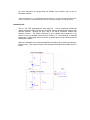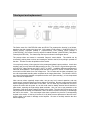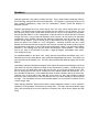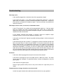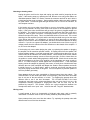
1
Sabre User's Manual Aiken Amplification, Inc. 1225 Montague Avenue Greenwood, SC 29649 Tel: 864-993-8383 http://www.aikenamps.com Contents Contents...............................................................................................................2 Getting Started.....................................................................................................3 Front Panel Controls and Switches...................................................................4 Rear Panel Controls and Switches....................................................................7 Tube layout and replacement...........................................................................10 Biasing................................................................................................................11 Speakers.............................................................................................................12 Troubleshooting................................................................................................13 Specifications....................................................................................................17 Getting Started Congratulations on purchasing your new Aiken Sabre amplifier! The Sabre is a 50W channel-switching amplifier featuring two EL34 tubes in the output stage. There are two completely separate channels, each featuring Gain, Bass, Middle, Treble, and Master controls, with a common Presence control, as well as two separate effects loops allowing individual effects to be used for each channel. The clean channel is capable of tones reminiscent of the finest old Fenders, while the gain channel takes you into modern modded high-gain territory. The gain channel also features a footswitchable gain boost to take the amp from crunch to over-the-top sustaining distortion - almost like having a three-channel amplifier. Features include: All-tube signal path. Preamp tubes are 12AX7/ECC83. Output tubes are EL34. The rectifier uses massive 3-amp 1000V ultra-fast recovery diodes (Ultra-FREDs), for utmost reliability and a tight low end, without the RF noise interference "spikes" inherent in standard rectifiers. Front panel controls/connections: Input jack, Channel 1 Gain, Treble, Middle, Bass, Master, Channel 2 Gain, Treble, Middle, Bass, Master, and Presence (affects both channels). There is also a bright switch for channel 1, a channel select switch, a gain boost switch for channel 2 (footswitchable), and a red and green LED to indicate which channel is active. A jeweled pilot lamp completes the look. Rear panel controls/connections: AC mains input, international voltage selector switch allowing operation at 100V/120V/200V/220V/230V/240V 50/60Hz, impedance selector switch for 4, 8, or 16 ohm operation, two 1/4" speaker jacks, and a footswitch jack to control the channel-switching and channel 2 gain boost functions. Also includes a locking mil-style RV6L bias pot and three tip jacks for easy bias setting without having to remove the chassis from the cabinet. There are also two separate line-level (+4dBu) effects loops (one for each channel) using a single 1/4" TRS jack for each (tip is send, ring is return, and sleeve is ground). Solid, finger-jointed, void-free birch ply cabinets. The head is 25 1/2" wide, 10 1/4" tall, and 9" deep. Hefty 16-gauge steel chassis, zinc-plated, yellow chromate conversion coated for durability, corrosion-resistance, and appearance. Front and rear faceplates are gold anodized aluminum for a durable, classic look. All hand-wired "military style" turret board construction, using chassis-mounted tube sockets, for ease of maintenance and reliability. Built to last. Finally - a high-gain channel-switching head that is not wired on a flimsy PC board! Premium, tight-tolerance parts are used for lowest noise operation, including 2W carbon film and metal film resistors where appropriate for best tone and lowest noise, 5W metal oxide power resistors, 630V axial-leaded polypropylene film/foil capacitors, and low-noise, sealed, 2W mil-style RV4 pots. SabreManual.doc 12/08/11 Copyright 2004-2011, Aiken Amplification, Inc. Page 3 of 17 Front Panel Controls and Switches Input jack: Plug your guitar in here and you are ready to rock! Ch1/2 select switch: This switch selects either the clean channel or the distortion channel. It should be in the “up”, or channel 2 position to enable normal footswitch operation, as it will override the footswitch setting. The red and green channel indicator LEDs will alternately illuminate when their channel is selected. Ch 2 gain switch: This switch turns on the gain boost function of channel 2. It should be left in the “up”, or boosted position to enable normal footswitch operation, as it will override the footswitch setting. Ch 1 bright switch: This switch changes the voicing of channel 1 to make it brighter for more high end “sparkle”. Unlike the bright switches on most amplifiers, it does not lose effectiveness as the volume is turned up. Ch 1 Gain: This is the clean channel gain control. It is primarily designed to compensate for guitars that have lower output single-coil pickups or high-output humbuckers. Turning the gain all the way up will give a bit of crunch with higher-output pickups if desired, or a more even clean tone when switching between lower-output single-coils and higher-output humbuckers in the same guitar. For the cleanest possible tone, turn the channel 1 Master up all the way and use the channel 1 Gain control as the overall channel volume. For the most clean sustain, turn the channel 1 Gain control all the way up and use the channel 1 Master to control the overall volume. Channel 1 Bass: The bass control adjusts the low frequency equalization of the clean channel. Channel 1 Middle: The middle control adjusts the midrange frequency equalization of the clean channel. Channel 1 Treble: The treble control adjusts the high frequency equalization of the clean channel. Channel 1 Master: The output level control is the overall level control for the clean channel. It should be used to equalize the volume between the clean and distortion channel when switching between them. Ch 2 Gain: This is the distortion channel gain control. For the cleanest possible tone, turn the channel 2 Master up all the way and use the channel 2 Gain control as the overall channel volume. For the most sustain and distortion, turn the channel 2 Gain control all the way up and use the channel 2 Master to control the overall volume. The “normal” setting for the gain control is around the 1 to 2 o’clock position. This will give a good crunch tone, and when the gain boost is turned on, it will give a very noticeable distortion/sustain increase for leads. If the gain control is turned all the way up, there will be much more distortion in the non-boosted mode, so the additional distortion added by the gain boost may not be as apparent. Of course, this setting is all dependent on guitar type and playing style, so it should just be used as a starting point for experimentation. Channel 2 Bass: The bass control adjusts the low frequency equalization of the distortion channel. Channel 2 Middle: The middle control adjusts the midrange frequency equalization of the distortion channel. Channel 2 Treble: The treble control adjusts the high frequency equalization of the distortion channel. Channel 2 Master: The output level control is the overall level control for the clean channel. It should be used to equalize the volume between the clean and distortion channel when switching between them. Presence: The presence control adjusts the high frequency equalization in the output stage. It is a "shelving" control that operates by cutting the amount of high frequencies in the global negative feedback loop, which results in a boost in the output high frequency range and a subjectively "brighter" and more "open" tone in the highs due to the lower negative feedback at those frequencies. The presence control frequency range is higher than most presence controls, and is primarily designed to add “sizzle” to the distortion channel, acting as a fourth eq control voiced above the treble control range. The treble and presence controls should be interactively adjusted to voice the top end of the distortion tone. Since it is a global control (it affects both clean and distortion channels simulataneously) if it is turned up too high, you may want to turn off the channel 1 bright switch or use less channel 1 treble to compensate. Note that a small amount of noise during rotation of the presence control is normal, and is due to a small DC voltage present on the control. This was deliberately done, in keeping with the "old-style" presence control circuitry that we feel sounds best. Pilot lamp: The pilot lamp lights when power is applied to the amplifier and the power switch is on. The pilot lamp features a screw-on “jewel” that can be removed from the front panel to replace the bulb without having to remove the chassis. The bulb is a standard #47 “bayonet” style bulb, available at most electronics supply stores. Power switch: The Power switch turns the amplifier on in the up position and off in the down position. Glory switch: What good is power without the glory? The Glory switch allows muting of the amplifier output when not in use. When the switch is in the up position, the amplifier is on, and when it is in the down position, the amplifier is on standby. The tube filaments remain on and warmed up, so the amplifier is ready to play as soon as it is taken off standby. The correct powerup sequence is to turn the amplifier on with the power switch and then, after it has had time to warm up, the Glory switch is turned on. When turning the amplifier off, the Glory switch should first be turned off, then the power is turned off after a few seconds. Rear Panel Controls and Switches AC Mains: Plug the supplied IEC mains cord into this outlet to provide power to the amplifier. Mains Fuse: 2A slo-blo for 100V/120V operation, 1A slo-blo for 200V-240V operation. AC Mains voltage selector: Set this switch to the appropriate position to match the mains voltage in the country in which you are using the amplifier. WARNING: Do not adjust this control with the AC mains cord plugged in and the power on!!! Damage to the amplifier will result if the switch is set to the wrong position. If you have any doubts as to which is the correct voltage for the country you are in, call the factory or inquire with someone locally who will know the correct mains voltage. HT Fuse: 500mA fast-acting fuse Impedance Selector: The impedance selector allows selection of 4, 8, or 16 ohm output impedance to match the speaker in use. Be sure to set this switch to the appropriate setting for the speaker or speakers connected to the amplifier. All amplifiers are shipped from the factory with a single 16-ohm speaker or a pair of speakers wired in series to provide a 16-ohm load. This allows connection of an external 16 ohm cabinet to be used simultaneously with the internal speaker by setting the impedance selector to 8 ohms, or four 16-ohm cabinets can be used by setting the impedance selector to 4 ohms. Speaker Jacks: Two speaker jacks are provided to allow use of the amplifier with either the internal speaker (combo units only) or up to two external speaker cabinets. More than two external cabinets may be safely used with the amplifier, but this will require the use of "Y" cables for the extra two cabinet connections. Be sure to use only quality speaker cable do NOT, under any circumstance, use guitar cable to connect the amplifier to a speaker cabinet. Doing so may cause damage to the amplifier. Bias Test Jacks: Three standard tip jacks are available to allow easy bias current measurements without removing the chassis. Refer to the section on biasing for instructions on the use of these jacks. Bias control: A locking mil-style RV6 trimpot is provided to allow adjustment of bias current. The outer locknut must be loosened before adjusting the screwdriver-slot control. Refer to the section on biasing for further instructions. Effects Loops: This is a 1/4" TRS (tip/ring/sleeve) insert style jack. There is a separate loop for each channel, and they function completely independently. The nominal 0dBu level allows use of line-level (pro) effects for lowest noise levels. The TRS insert jack allows use of a single TRS cable to connect the effects, instead of the two 1/4" cables normally required for an effects loop. The TRS cable (also called an “insert” cable) is a cable that has a stereo ¼” jack on one end and breaks out into two mono ¼” jacks that go into the input and output of the effects unit. These insert cables are available at most music stores (they are typically used to connect compressors or other effects to a single channel on a mixing board). Alternately, you can make or buy a stereo to two-mono “pigtail” adapter cable (available from places like Radio Shack) and use standard ¼” cables to connect the effects. Once properly connected, adjust the effects unit’s input level control so the signal presence LED is lit (if there is one) and the clip LED occasionally lights on peaks or doesn’t light at all, depending on the effect’s requirements. Then adjust the effects unit’s output level so the Sabre’s volume is the same with the insert cable plugged into the back of the amp or unplugged. Refer to the effects unit user manual for proper adjustment in case it differs from these instructions. Although there are two independent effects loops, it is not necessary to use two separate effects units with the Sabre. Most rack mount effects are stereo, and have independent channels when both are used. To use a single stereo effects unit with the Sabre, simply connect two TRS cables, one from each effects loop jack, to the inputs/outputs of the stereo effects unit. Of course, the same effects patch will be active for both channels, so you will have to change channels and effects patches at the same time to have different effects on each channel. There are midi footcontrollers on the market that will allow control of amplifier channel switching and effects patch changes at the same time. There is, however, a more elegant solution to using a single effects unit: the TC Electronics G-Major multi-effects processor. This is the recommended effects unit for use with the Sabre. It has a unique relay output jack feature that is perfectly suited for use with the Sabre’s footswitchable functions. This is a stereo output jack that has two indepent patch-controllable relays connected to a single stereo jack on the rear of the unit. By simply connecting a stereo cable from the relay output jack on the G-Major to the stereo footswitch jack on the rear panel of the Sabre, and connecting two TRS cables from the effects loop jacks of the Sabre to the inputs/outputs of the G-Major, you can program and control G-Major effects patches, Sabre channel selection, and Sabre boost switch functions all at the same time with a single patch change on the G-Major (or single step on the G-Major’s footcontroller). For more information on programming the G-Major relay function, refer to the TC Electronics manual*. Aiken Amplification is in no way affiliated with TC Electronics, we just were told about this effects unit from a customer, and decided that it looked like it was tailor-made for use with the Sabre! * Footswitch jack: This is a 1/4" TRS (tip/ring/sleeve) insert style jack. The tip connection controls the channel switching function, and the ring connection controls the gain boost function of the distortion channel. Shorting the tip or ring to the sleeve connection enables that particular function. The sleeve connection is not at chassis ground potential, so be careful to only use isolated contact closure functions, i.e. relay switching or standard footswitches. Shorting the sleeve connection to chassis ground or AC mains ground will damage the amplifier. Below is a schematic of the recommended Sabre footswitch wiring, should you decide to build your own. This is the schematic of the footswitch that ships with the Sabre from the factory. Tube layout and replacement The Sabre uses five 12AX7/ECC83 tubes and EL34. The preamp tube function is as follows, starting at the side closest to the input jack: CH1 preamp 1/CH2 preamp 1 (12AX7/ECC83), CH1 effects recovery amp/CH2 preamp 2 (12AX7/ECC83), CH2 preamp 3/CH2 preamp 4 (12AX7/ECC83), CH2 effects recovery amp/CH2 cathode follower (12AX7/ECC83), and phase inverter(12AX7/ECC83). The chassis top view layout is shown in the diagram above. The preamp tubes are housed in removable "bayonet" metal shields. The shields can be removed by pushing down on them and rotating the shield to the left, then pulling it upwards off the tube. The tube can then be pulled out of the socket. You may freely sub any 12xxx type tube in the preamp and phase inverter positions. It won't hurt anything, and you may find some different tones you like. The 12AU7 is a good lower-gain tube, as is the 5751. Other choices are 12AY7, 12AT7, or 12AZ7. In addition, different manufacturer's tubes will sound different. Some people prefer the tone of various Ei, Sovtek, or other tubes, and some insist on NOS tubes for a true vintage tone. The JJ/Teslas are the least microphonic, but are a bit compressed sounding when compared to the longer-plate tubes. The Chinese 12AX7’s are a good compromise between microphonics and a more “open-sounding”, or less compressed tone. Feel free to experiment! Note: vacuum tubes, especially output tubes, can get very hot in normal operation, and may cause burns if removed before they have a chance to cool down. Be sure to wait several minutes before replacing tubes to allow them to cool down. Do not, under any circumstances, remove or replace the tubes with the power on, as this could cause a deadly electrical shock should the glass break, exposing the high-voltage plate terminals. Also, be sure to pay attention to the orientation of the tubes when putting them back in the socket. The tube pinout is keyed so it can only be placed in the socket in one direction, and if the tube is forced in incorrectly, it can damage the tube or the socket. The octal output tubes have a phenolic key that fits a corresponding keyhole in the socket. If this key is broken off, it will allow incorrect placement of the tube in the socket, which could result in damage to the amplifier. Be sure to carefully examine the tube before replacing it. Biasing Biasing is very easy, and doesn't require removing the chassis from the cabinet. You simply use a voltmeter (any inexpensive digital multimeter will do), set it for the smallest DC voltage range (typically 200mV). Then: (1) Unplug any guitar cords going into the input jack. Turn the two volume controls all the way down (other control positions don’t matter). Unscrew the lock nut on the bias pot on the rear panel, and turn the bias control all the way down (counterclockwise). Turn the Power switch on, wait a minute or so until the tubes have warmed up, then turn on the Glory switch. Wait a few more minutes for the tubes to reach their stable operating point. (2) Put the negative probe lead into the black tip jack (leaving the positive probe in one of the red tip jacks - it doesn't matter which one), and adjust the bias pot for a maximum of 45mVDC (that's 45 millivolts, not 45V!). See note below for more information on the acceptable and recommended bias value. (3) Put the red meter probe leads into the other red tip jack and check for a maximum of 45mVDC. If the reading is higher than 45mV, adjust the bias pot down until the meter reads 45mVDC. If it is lower than 45mVDC, leave it set where it was. Note: if the two readings differ by more than 5mV to 10mV, this indicates that the two tubes are too far out of match, and they probably should be replaced with another set that are better balanced. However, it will not harm the amplifier to use unbalanced tubes, as long as the bias pot is set for 45mV on the highest current side. Check the voltage from the black tip jack to the left red tip jack and then to the right red tip jack, and adjust the bias for 45mV on the highest reading side. An imbalance can sometimes even sound good! Too high an imbalance, however, can cause high levels of hum in the output and loss of low end response. (4) Once the bias is set, tighten down the lock nuts on the bias trimpot and you're ready to play. Note: The 45mV setting given above should be considered a maximum setting. It is perfectly acceptable to bias at a lower setting. This will result in longer tube life, lower background noise, and a cleaner tone, although if you go too low the increased crossover distortion may become objectionable. You may prefer the tone with the tubes biased colder, so feel free to experiment, it won’t hurt anything as long as you don’t bias the tubes too much hotter than the recommended setting. Our “optimum” bias point we set the amp to at the factory before shipping is around 35mV - 40mV. Note: It is normal for tubes to drift a bit, particularly when new, until they have had several hours of playing time on them. The bias will also vary a bit with variations in AC line voltage (a Variac is used to set the AC line voltage to 120V at the factory before biasing the tubes). Small variations like this shouldn't cause any problems, so don't worry about constantly checking the bias and driving yourself crazy trying to keep it at exactly the setting you chose. If a tube is biased too hot, the plate will glow a dull red color. The plate is the large grey metal "box" structure seen inside the tube. Don't confuse normal filament glow with plate glow. Plate glow can usually be seen as a "hot spot" near the center of the plate, sometimes accompanied by a "hot" smell and some "ticking" noises as the metal expands. Continued operation with glowing plates will soon result in failure of the tubes, possibly damaging screen grid resistors or other amplifier components. The HT fuse should prevent any major damage to output or power transformers, or other expensive components. Speakers Changing speakers is like getting a whole new amp. Every model sounds completely different, some sounding quite good and some amazingly bad. The amplifier is particularly suited for use with Celestion loudspeakers, which give the characteristic "British" sound this amplifier is designed to create. Celestion Greenbacks have less volume and a dip in the mids, which makes them nice and smooth. The amplifier was voiced for this speaker in a 4x12 cabinet or a 2x12 cabinet. They are rated at 25W, so they make a good match for the Sabre in a 2x12 or 4x12 cabinet, but are underrated for the 50W Sabre in a 1x12 configuration, so they shouldn’t be used in that case. Celestion Vintage 30's have a very pronounced midrange, which may be a bit too harsh in an open-back configuration, which naturally enhances the midrange frequencies, and can sound a bit "boxy" with the wrong speaker. They do sound good for some blues and rock styles, and can easily handle the power of the Sabre in a 1x12 configuration. Celestion G12H30's are like a cross between the Greenback and the Vintage 30, with more low end than the Vintage 30 and not quite as pronounced a midrange, so they tend to sound subjectively "better" in an open-back cabinet. Eminence is now making some very nice British and American voiced speakers. Their Private Jack is very close to a Greenback, but louder, a slight bit brighter, and handles more power. Your mileage may vary. Our standard speaker is the Aiken A12L, which uses the actual British Greenback cone, but is assembled here in the United States, using a different magent/basket structure. It has better low end, but retains the Greenback tone. This is the same speaker Mojo Musical Supply sells as their BVM-25. Closed-back cabinets have better and tighter bass, without the pronounced midrange hump of the open-backs, but they don't disperse on stage as well, and tend to be "beamy", sounding very loud out front, but if you stand above and to the front or back, you can't hear yourself as well. Still, there is nothing quite like the tone of a cranked up 4x12 cabinet loaded with Greenbacks! For a more portable closed back, a 2x12 loaded with either of those Celestions will do the trick nicely. Putting a 2x12 on each side of the stage fills up the tone very well, and provides an almost stereo-like sound field because of the cancellations that occur when standing in different places on stage. The Greenbacks are the recommended speaker for 2x12 and 4x12 cabinets for the “classic vintage” tone. When changing speakers, always insure that the output impedance selector is set to match the impedance of the speakers connected to the output jacks. The Sabre has two paralleled output jacks, and can easily drive two 4x12 cabinets to extremely loud volume levels, despite the 18W rating. Troubleshooting Pilot lamp not lit: Is the amplifier plugged into a functional outlet of the appropriate voltage? Is the mains fuse blown? If so, replace with the appropriately rated fuse. If the fuse again blows, the amplifier may have a shorted output tube or rectifier tube. Replace the tubes and fuse, and power the amplifier up again. If the fuse still blows, the amplifier will need to be serviced. Pilot lamp lit, but no sound, low sound, or intermittent sound: Is the HT fuse blown? If so, replace with the appropriately rated fuse. If the fuse again blows, the amplifier may have a shorted preamp tube, output tube or rectifier tube. Replace the tubes and fuse, and power the amplifier up again. If the fuse still blows, the amplifier will need to be serviced. Is the speaker functional and plugged in correctly? Insure the amplifier's output impedance selector is correctly set to match the speaker in use. Is the guitar cord functional? Bypass any pedals and plug straight in with a known good cable to test. Is the effects loop jack dirty or broken? Try plugging a cord into the effects loop jack and back out several times to “clean” the jack contacts. If the sound comes back, you may need to take the amp in for replacement of the jack or for cleaning of the switching contacts on the jack (these bypass the loop when nothing is plugged in, and may get dirty and become intermittent). In a pinch, you can buy a stereo plug from Radio Shack and solder the tip and ring terminals together and plug it back into the effects loop jack. This will be a removable “bypass” plug that will allow the amp to properly function if the effects loop jack has become intermittent or the switching contact has been broken. No effects: Is the insert cable fully plugged into the jack on the back of the chassis? Is the effects unit designed for pro level (0dBu nominal, +4dBu max) levels? The Sabre will not work with “stompbox”, or guitar-level effects, as they are designed for very low guitar signals. Is the effects unit in bypass mode? Does the signal presence LED (if there is one) on the effects unit light when you hit a chord? Footswitch doesn’t change channels or turn boost on/off: Are the front panel channel select and boost switches both in the up (on) position? Humming or buzzing noise: Unplug the guitar cord from the input and unplug any cable used for jumpering the two inputs. If the buzzing stops, try replacing the cord. Be sure to use only guitar cables, not unshielded speaker cables! If in doubt, unscrew the connector and look to see if there is a shield around the center connector. Some smaller speaker cables are easily mistaken for guitar cables. Fluorescent lights and light dimmers can be a source of hum/buzz, as can computer monitors. If the buzzing only occurs when using effects or a tuner, the problem is likely a ground loop hum (in particular, the Korg rack mount tuner seems to be susceptible to ground loops). If this is the case, the hum/buzz will go away if the guitar is plugged straight in to the amplifier. The solution is to use a ground loop hum eliminator (there are a few on the market) or make a guitar cord with a "telescoping shield" to go from the output of the effects to the input of the amp. This is a cord with the shield cut on one end. The cut end should go into the amplifier input jack, and the end with the shield must go into the output of the effects unit/tuner. In a emergency, a ground lift plug (three-prong to two-prong adapter) can be used on the tuner/effects box, but this is not recommended due to safety concerns. If you do use a ground lift adapter, you should check to see if there is any AC voltage present from the chassis of the rack effect/tuner to the chassis of the amplifier. If so, do not use the adapter! If the buzzing only occurs when playing the guitar, try replacing the speaker or plugging the amplifier into an extension speaker cabinet. A buzzing noise from the speaker can indicate a blown speaker, or one with a warped frame. Buzzing noises that occur only on certain notes can be indicative of a cabinet problem. Check all rear panel screws, handle screws, and chassis mounting screws to insure they are tight. Check to insure there are no speaker or reverb cables rattling against the baffle board. Check the two screws that hold the nameplate to the front of the amplifier, as the nameplate can cause a rattle or buzz if it is loose enough to vibrate against the front panel board. If the nameplate buzzing cannot be stopped by tightening the screws, a small piece of double-stick tape affixed to the rear of the nameplate will dampen the vibration. Some speakers are known to exhibit "cone cry", or "ghost noting", which is a second, out-of-tune note that occurs only when playing certain notes on the guitar. If this is suspected, try another speaker to see if the problem goes away. Some preamp tubes are more susceptible to filament-induced hum than others. The 12AX7/ECC83 is a dual triode (two tubes in one package), and some tubes will exhibit hum in only one of the two sections, or in both. Try replacing the preamp tubes with different ones to see if the hum decreases. The JJ/Tesla ECC83S is the least microphonic and least noisy current-manufacture tube we have found, but are a bit compressed sounding compared to longer-plate tubes, and as such, may not be preferred by everyone. The Chinese 12AX7s are a good compromise between low microphonics and a more “open” tone. I also like the new “Tung-Sol” branded tubes. Hissing noise: A small amount of hiss is a characteristic of high-gain tube amps, and is generally unavoidable. Excessive levels of hiss are usually caused by bad preamp tubes. Some preamp tubes have more hiss than others. Try replacing the preamp tubes with different ones to see if the hiss decreases. "Ticking" noise: Some tubes (particularly JJ ECC83) tend to exhibit a low-level "ticking" noise right after the amplifier is taken off standby. The noise stops after a second or two, when the tube has had a chance to stabilize, and is not indicative of a problem. Ringing noise or feedback that occurs with no guitar plugged in: If the amplifier exhibits a "ringing" noise, especially when tapping on the chassis, or if it makes a howling or whistling feedback noise when the volume is turned up but no guitar is plugged in, there is probably a microphonic tube in the amplifier, likely in the first position (the small tube closest to the input jacks), or in the reverb recovery position. Remove the shield and lightly tap on the tube with the volume turned up. A small amount of noise is normal, but a loud, ringing noise indicates a microphonic tube, which should be replaced. In a emergency, you can swap the other 12AX7/ECC83 preamp tubes around until you find the least microphonic one to put in the first position. Typically, the phase inverter tube is the least susceptible to microphonics, so the most microphonic tube should be used in this position. The least microphonic tube should be used in the first position, and the next least microphonic tube should be used in the reverb recovery position. When purchasing tubes, be sure to purchase tubes that have been tested for microphonics. Many vendors do not test for microphonics, and you could end up wasting your money on tubes that are unsuitable for use. Combo amps are more susceptible to microphonics than heads, because the sound field coming from the back of the speaker can excite the tube into oscillation. In rare cases, the EL34 output tubes can be microphonic, particularly if they are at the end of their lifespan. Fuse blowing: An amplifier typically has two fuses - one for the "mains" or AC supply, and a second one for the "HT" or high-voltage section of the amplifier. It is perfectly normal for a blown mains fuse to shut the entire amp down. That's the fuse’s job - to shut the amp off to protect it in the event of a short circuit. Sometimes a fuse will blow for no apparent reason (called "nuisance" fuse blowing). An amplifier has large filter capacitors that can draw quite a bit of inrush current when the amp is first turned on and they are fully discharged, and this can occasionally cause a fuse to blow, particularly if the fuse is old. If your amp blows a fuse, you should replace it with one of the same type and rating. If it still blows the fuse, the amp needs further servicing. The HT fuse should be a fast-acting type, and the mains fuse should be a slo-blo type. If your Sabre blows the HT fuse, it is most likely caused by a bad EL34 output tube, or incorrect bias setting (usually accompanied by red glowing plates in the tubes and a very hot running amplifier). If it blows the mains fuse, immediately on power up every time, it is most likely a bad rectifier diode. If it just occasionally blows the mains fuse, you may want to go up one size in fuse to prevent this “nuisance” blowing. If you are using a 2A fuse, try a 2 ½ or 3 amp fuse, but don’t go any larger or you may damage the power transformer in the event of a real failure. Troubleshooting steps: (1) First pull out both EL34 output tubes and put in a new fuse. Turn the amp on. If the pilot light comes on, the power transformer and wiring and rectifier diodes are fine. Let it run for a few minutes to make sure the fuses don’t blow again. Then proceed to troubleshooting step 3. (2) If the mains fuse blows immediately upon power up, you likely have blown rectifier diodes. These can easily be replaced by any competent technician. They are located in the upper right corner of the chassis, below the voltage selector and mains fuse, mounted on blue standoffs (when replacing the diodes, be careful not to to break these standoffs. It is best to carefully cut the diodes out, then unsolder the leads to avoid stressing the standoff). Here is a picture showing the diodes on the standoffs: The HT rectifier diodes are on the left, connected to the filter capacitor, and the bias supply diodes are on the right of the standoffs. Early Sabres used two bias supply diodes, later models used only one (with some different value components on the main board as well – see Service bulletin 1 for details). The Sabre uses 1000V 3A FR307 fastrecovery rectifiers (available online from Digikey at http://www.digikey.com), but you can substitute standard 1N4007 diodes if necessary. For added protection against future rectifier failure due to voltage surges, use two diodes wired in series in place of each of the diodes (this is addressed in service bulletin 2). Be sure to replace all the diodes, not just the bad one, in case the amplifier was subjected to a voltage surge, which may have marginally damaged one of the other diodes. There is a small chance fuse blowing can be caused by a bad filter capacitor or power transformer, but this is highly unlikely, unless the amplifier is very old or has been subjected to misuse, line voltage surges, or incorrect setting of the mains voltage switch. (3) Next, install the power tubes. If the fuse blows, one of the output tubes is bad, and the entire set should be replaced. If the fuse doesn't blow, and the amp works fine, it was likely just a nuisance fuse blowing, and the amp should be monitored carefully for the first hour or so of playing just to make sure everything is okay. Never keep feeding fuses to an amp that is blowing them, you'll likely cause permanent damage. Stop after the second one blows, unless you've isolated the cause as I've described it above. Specifications Output Power: 50W RMS at onset of clipping into resistive load at rated impedance. Input Impedance: 1 Megohm Input sensitivity: < 1mV for full clipping, channel 2 Tube complement: Five 12AX7/ECC83 preamp tubes, two EL34 power tubes. Fuses: 100V-120V: Mains: 2A slo-blo, HT: 500mA fast-acting 200V-240V: Mains: 1A slo-blo, HT: 500mA fast-acting Dimensions: Head: 25.5" W x 10.25” H x 9" D Weight: 50W head: 43 lbs