1
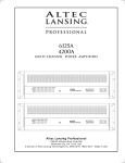
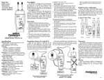
A M P L I F I E R S
RM100
MODULAR TUBE HEAD
O W N E R S M A N U A L
Dear Randall Owner,
Congratulations on the purchase of your new Randall Amplifier, and thank you for the support of our product line. Randall amps are made
to strict quality and consistent performance standards, that will provide you with years of musical satisfaction. Please read the following
manual, before operating your new Modular amplifier. The innovation of the new MTS series, will take tube versatility to new heights, and
your journey begins today. The quick start guide should help get you going, but if you ever have any questions or comments, please contact
us anytime.
Enjoy your new purchase!
Warnings:
-Do not block any ventilation openings on the front and rear of the head. Always give four inches of proper ventilation to the rear of the
preamp.
-Do not expose the amplifier to rain, moisture, dripping or splashing water. Do not place objects filled with liquids on or nearby the amplifier.
-Do not expose the amplifier to direct sunlight or extremely high temperatures. Always unplug the AC power cord before changing fuses or
tubes. When replacing fuses, use only the same type and rating.
-Be sure to connect to an AC power supply that meets the power supply that meets the power supply specification, listed on the rear fuse
holder.
-If there is any danger of lightning occurring nearby, remove the power plug from the wall socket in advance.
-Do not use excessive force in handling control buttons, switches and controls. Do not use solvents to clean the unit, wipe off the exterior
with soft cloth.
IMPORTANT SAFEGUARDS
THESE WARNINGS APPLY TO ALL RANDALL ELECTRONIC PRODUCTS. PLEASE READ AND OBSERVE ALL
WARNINGS AND INSTRUCTIONS CONTAINED IN THIS SERVICE MANUAL AND THOSE ON YOUR RANDALL
PRODUCT PRIOR TO ITS USE.
WARNINGS AND SYMBOLS:
LIGHTNING FLASH: The lightning flash with
an arrowhead within an equalateral triangle, is
intended to alert the user of the presence of
uninsulated DANGEROUS VOLTAGE within
the product’s enclosure that may be of
significant magnitude to constitute risk of
electric shock to persons.
IMPORTANT SAFEGUARDS
THESE WARNINGS APPLY TO ALL RANDALL ELECTRONIC PRODUCTS. PLEASE READ AND OBSERVE ALL
WARNINGS AND INSTRUCTIONS CONTAINED IN THIS SERVICE MANUAL AND THOSE ON YOUR RANDALL
PRODUCT PRIOR TO ITS USE.
PRECAUTIONARY WARNING:
RAIN AND MOISTURE: To reduce the risk of
fire or electric shock, DO NOT EXPOSE THIS
UNIT TO RAIN OR MOISTURE. Operators of
electronic products should in no way be in
contact with water.
WARNINGS AND SYMBOLS:
LIGHTNING FLASH: The lightning flash with
an arrowhead within an equalateral triangle, is
intended to alert the user of the presence of
uninsulated DANGEROUS VOLTAGE within
the product’s enclosure that may be of
significant magnitude to constitute risk of
electric shock to persons.
PRECAUTIONARY WARNING:
RAIN AND MOISTURE: To reduce the risk of
fire or electric shock, DO NOT EXPOSE THIS
UNIT TO RAIN OR MOISTURE. Operators of
electronic products should in no way be in
contact with water.
Replacing modules: When exchanging modules, simply turn
both thumbscrews to the left until they fill loose.(Do not
remove the screw completely). Remove the module pulling
out on the thumbscrews. Slide in a new module, and push in
on the center knobs until flush with the front panel. Tighten
the thumbscrews, by turning to the right until snug.
Quick start guide:
Hooking up your gear:
After plugging in the AC power cord, connect a 1/4” instrument cable from the pre or post loop output to the input of your power amp. If
your using your effects loop, use only the post loop output. If you have the foot controller(optional), connect the foot controller to the
MIDI In on the rear panel. After turning on the unit, plug your guitar into the front panel input. Select the desired preamp module, and
adjust each level to 12 o’clock to start. Slowly bring up the master level until your reach the desired volume level. Then adjust the EQ settings on the module to your desired setting. Select the next module and repeat this process.
Channel Switching:
If there are four preamps installed, pressing & releasing the channel select switch will change the channel from 1 to 2, pressing &
releasing again 2 to 3, and again 3 to 4.
Saving a Preset:
Pressing and holding the channel select switch for 2 seconds will store your current settings. When used with the foot controller, select
button 1 on the foot controller, then set to channel 1 using the front panel channel switch button. (both the footswitch and channel 1 light
should be lit). Press and hold the channel select switch for 2 seconds, and this will store your current settings with the footswitch. The
footswitch will not select any preferred channel. To reset, simply turn the preamp off/on, and repeat the above steps.
Front panel Features and controls:
The RM100 front panel consists of 1/4” input, channel switch, effects level, Master level, Density & Presence controls. Read below for
descriptions of each.
Input Jack: The main guitar input. Using a high quality instrument cable connect your guitar to this input.
Channel switching: Each module can be changed by either pressing the front panel button, or with the included MIDI footswitch. Simply
press and release the front panel button to change modules. When using the MIDI footswitch plug into the input on the rear panel, and
select the channel you desire on the footswitch. To program the footswitch, simply press the button 1 on the footswitch, and set the head
to channel 1 using the front panel button. Press and hold the front panel button for 3 seconds, and it’s now programmed. Repeat this
process for channel 2 and 3.
Front panel Effects level: This knob controls the amount of effects when used with the parallel effects loop on the back panel. Simply
plug in your outboard effects unit into the parallel effects loop on the back panel, and adjust the level on RM100 front panel.
Front panel Master level: The master level is a master volume for all the preamps. adjust each preamp level to your desired level, than
adjust the master level for overall volume.
Density Control: This knob boosts the amount of overall low end in your guitar tone. A master low end control that should be set to your
desired liking.
Presence Control: This knob boosts the overall high end frequencies of your guitar tone. A master high end control which should be set
to your liking.
The Preamp Modules: At print of this manual there are 12 different preamp modules available. Please check our website or call for
information on new modules to date. See below for module features.
The Module Tone Controls:
Each module consists of 5 different controls with bright switch. Please read below for description of each.
Gain control- Adjusts the amount of desired distortion and gain. Each module has a different type and level of distortion.
Bass control - Adjusts the amount of desired bass frequency. To get started set each knob straight up.
Middle control- Adjusts the amount of mid-range frequency. Also set straight up to get started.
Treble control- Adjusts the amount of high frequency. Set straight up to get started.
Level control- Adjusts the amount of volume for each module. Set each module to a similar level, and adjust the master level to the
desired volume.
Bright switch- The bright switch adds additional high end presence to your tone. Each module has a different level of bright adjustment.
Turn the bright switch on or off depending on your desired tone.
1
2
3 4
5 6 7 8
1. Input jack: 1/4” input for your guitar. Connect you guitar to this input jack.
2. Channel switch: Push and release button to switch between channels 1-2. Each module can be selected by either pushing this button
or by the single footswitch (included)
3. Master level: Each module has it own level control. This adjusts the desired amount of volume for each module. Please adjust each
module to similar volume level, than use this master volume control to adjust overall volume.
4. Effects control: This knob is used when using the parallel effects loop on the rear panel. Hook up your external effects processor to the
parallel effects loop, and control the amount of effect with this front panel knob. Turn to dry for no effects, or wet for maximum effects.
You can also adjust the level control on your effects processor for additional control of the effects. It is important to set your effects
processor to 100% wet, before using the front panel control.
5. Density: This knob control is the master low end control for your tone. Adjust this knob up an down to control the amount of low end
density. Set each module to the desired tone, than use this knob to boost or cut the overall low end frequencies.
6. Presence: This knob controls the amount of overall high end presence control. Once you set each module to your desired tone, this
knob can be used as a cut or boost of the extreme high end frequencies.
7. Standby/Play switch: The switch is mainly used to protect and save the life of your power tubes. Once the power has been turned on,
this switch puts your amplifier in standby or play mode. Please switch to standby position when not using the amp, to save the life of your
power tubes. Select to the Play position when ready to use the amplifier. Always switch to Standby position before turning off the power
switch. It is recommended to turn on the main power switch, and allow the amplifier to warm up shortly before turning this switch to play
mode.
8. Power switch: This is the main AC power switch. The switch turns the power on or off for the amplifier.
Rear panel special features and controls:
MIDI in/thru:
Connect the included 7-pin MIDI footswitch and cable to the MIDI in. The thru can be run to any external effects processor, which can then
be used to program effects to your different module channels.
Tube Bias Section:
This amplifier includes a biasing section for changing or replacing your power tubes. When changing power tubes it is very important you
bias each tube correctly for optimal preformance.
See the bias section on page following page.
Impedance select:
From the factory your head has been preset to the 8 ohm position. When using an external speaker cabinet, you may adjust this switch for
proper ohm load of you external speaker cabinet.
Parallel effects loop:
Used to connect any outboard effect processors.
Use the parallel effects loop for “time based” effects, such as delays, reverb, etc. The
desired effect can than be adjusted using the front panel mix control. See detailed uses of the parallel loop on page 9-10 of this manual.
Series effects loop:
Also used to connect your outboard effect processors. A general effects loop, not to be used with the front panel mix control. See detailed
uses of the parallel loop on page 9-10 of this manual.
Effects loop tubes:
Each effects loop utilizes two 12AX7 tubes to buffer your processing gear.
Any outboard effects processing used through the effects
loops, go through the tubes to warm the sound of any signal processing.
Common Input tube:
Each module also utilizes one common input tube, installed on the top panel of the amplifier. Your guitar signal always passes through this
input tube first before each module, so each preamp modules uses three 12AX7 preamp tubes to help generate the pure tube tone.
1
2
4
3 5
6
7
8
9
10 11
12 13
1- AC Power/Voltage Selector: This amplfier can operate at AC currents of 100V, 110V, 120V, 230V. Simply remove the fuse with a
small screwdriver, and line up the correct voltage with the arrow, and plug back in. After selecting the correct voltage, connect the AC
power cord the wall socket.
2- MIDI in/thru inputs The RM100 includes a 7-pin MIDI cable and 3-button footcontroller.
Connect the MIDI cable to the footcontroller
jack, and MIDI in on the rear panel of the head. The MIDI thru can be used to connect to the MIDI in of external effect processors, that
are MIDI capable.
3- Test Points: Positive test points for adjusting the bias of each power tube. Refer to the bias adjust on page 10 & 11.
4- Common:
Common ground input for adjusting the bias of each power tube. Refer to the bias adjust on page 10 & 11.
5- Bias adjust: Small screw adjustment for adjusting the voltage on each power tube. Refer to the bias adjust on page 10 & 11.
6- Impedance select:
Set this switch to the correct ohm rating of your internal and external speaker cabinet.
7.- Main Output: This is the main output, which is currently connected to your internal speakers. This can also be used as the main output for an extension cabinet.
8- Extension Output: Used to connect to an external speaker cabinet. It is very important that you select the correct impedence when
adding an extension cabinet.
9- Slave out: This is a direct signal output, and is generally used to connect to other power amplifiers. When preforming in large venues,
you may need additional volume and coverage. It can also be used to send a signal on to amp switchers or effects processors.
10- Parallel Loop Return: Connects to the output of any external effects processor. Please refer to the effects guide on page 9/10.
11- Parallel Loop Send: Connects to the input of any external effects processor. Please refer to the effects guide on page 9/10.
12- Series Loop Return: Connects to the output of any external effects processor. Please refer to the effects guide on page 9/10.
13- Series Loop Send: Connects to the input of any external effects processor. Please refer to the effects guide on page 9/10.
MTS Series
EFFECTS LOOP Operations
The MTS effects interface is the most versatile loop system you will find anywhere. There are two totally ndepenent loops, each
optimized for specific functions and applications.
1) SERIES LOOP:
Basically an insert patch point. When an external effect is patched into the send and return jacks, the path is interrupted
and 100% of the signal is routed through the effect. This puts some special demands on the effects unit. It must be essentially
transparent, meaning, it shouldn’t “mess” with your tone. The input and output levels must be properly set for maximum
headroom and lowest noise and it needs to operate at line level. Proper setting of the levels can be achieved using the following
method.
a) Set your amp/preamp volume levels for mormal playing levels. Connect a high quality instrument cable from the series loop
send jack to the effect input.
b) Adjust the effects unit input level to “just peak” while playing your most aggressive licks.
c) Now connect another high quality instrument cable from the series return loop jack to the effect output.
d) Adjust the effects unit output level to the match the volume you heard before connecting the return cable. You can check this by
pulling the cable in and out of the return jack while playing and verifying there is no substantial volume difference. this is called
“UNITY GAIN”.
2) PARALLEL LOOP:
This is a more specialized loop. It has the advantage of maintaining your dry signal (it doesn’t mess with your tone), while
allowing you to mix in the amount of effect you want. The MTS parallel loop is a bit different. Most parallel loops found on guitar
amplifiers have a wet/dry mix control that turns down the dry signal (messing with our tone) while simultaneously turning up the
effects level. Our MTS parallel loop is unique because it never messes with your dry tone, and simply mixes in the amount of
effects using the effect knob on the front panel. Much like the effects buss on a mixing console. The direct signal remains
unaltered and the effects are simply mixed back in. There area few basic rules that must be adhered to and this also puts some
limitations on the uses for the parallel loop.
a)Your effects unit must be set for 100% wet. This means set the mix levels on the effect so that there is no dry signal passing
through the unit. Think of the mixing console again. You would not want to have any dry sigal going though the effects buss
because you would then be mixing in not only the effect but also the unwanted dry signal the comes out of the effects unit.
Parallel Loop- cont.
This can even be derimental to your tone, because the dry output signal of many effects units is out of phase with the input.
Consequently, as you turn up the effects return knob, you may actually be mixing the “Bad” out of phase signal back in with your
awesome dry signal... this is definitely now messing with your tone. Often loops on guitar amps are said to “suck tone”. this “tone
sucking” is more likely caused by improperly setting the effects mix than the loop design.
3) Now let’s discuss the specific uses, advantages, disadvantage and limitations of each effects loop.
a) The Series loop, by nature of the fact that it breaks the direct path and processes 100% of the signal, makes it so that
essentially any line level gadget will work. You can use echo, reverb, noise reduction, tremolo, equalizers, etc in the loop.
Remember to follow the procedure for setting for “Unity gain”.
Advantages are: Works fine with just about any effect. No special requirements, other than the “unity gain” settings, are
needed. Basically you can Plug in and Play.
Disadvantages: The entire signal passes through the effects unit and is more apt to mess with your tone.
b) The Parallel loop, on the other hand has more limited uses, but has the distinct advantage of not messing with your
tone. This loop is ideally suited for what are called “time based effects”. This includes delay, reverb, chorus, flanging.
These types of effects work in parallel with your direct dry signal is always present. You cannot use effects that require
processing 100% such as equalizers, noise reduction/gates, tremolo or compressor/limiters.
Advantages are: Doesn’t mess with your dry tone. Easy to adjust the effects level with the front panel effects knob.
Disadvantages are: It has limited uses and may require reprogramming of your effects unit.
4) Special Notes:
a) A concern is the fact that many multi-effects units have a combination of all of the different effects. This mean, using
the parallel loop, you must be aware of which effects can and can’t be used. For ease of operation, we recommend using
the series loop if you intend to use a mix of different “time based” and non- “time based effects in one unit.
b) Both loops are for line level operation. Though some floor type and tabletop effects may work, the loops are designed
basically for rack mount type effects units. Not guitar level floor pedals. You will know an effect is not made for line level if,
when you plug it into the loop, you notice distortion and a loss of volume.
MTS Power Tube Bias System
What is bias? Simply put, it is a circuit inside the power amplifier section that controls the “idle current” that flows through the
power tubes. Much like the idle speed on a car. There is an optimum setting where the engine (amplifier) is running (idling) fast
(hot) enough to keep it from stalling (distorting) but not too fast (hot) to cause excessive wear and overheating. Get it?
Why don’t all amplifiers have bias or idle current adjustments?
Most do but typically involve removing the amp chassis from the box, exposing you to very dangerous high voltage. Special test
equipment and knowledge of amp circuits and tubes is also needed. Not a skill most musicians possess and shouldn’t need to.
Why would I want to adjust the bias?
All power tubes are different. They all have unique sonic and electrical characteristics. The MTS amplifiers are designed to
accept a variety of different tube types. EL34, 6L6, 5881, 6CA7 and 6550 are among the possible choices. Because they are
all different, they each require different bias settings for safety, reliability and optimum performance.
Please read the following instructions on how to use this cool feature…….
The MTS Series of products from Randall takes the danger and mystery out of bias and puts it safely into the
users hands.
You will need a decent quality digital voltmeter capable of measuring in the 100 millivolts DC range. This is a very basic type of
meter available at any electronic supply house or Radio Shack. They typically cost anywhere from $10 to $25. About the cost
of one bias adjustment from your local amp tech.
You will also need a small, flat blade screwdriver to turn the adjustment control.
1) The amp should be on, standby in the “PLAY” position and all knobs all the way down.
2) Turn the meter on and set for reading DC millivolts. Consult the meter instructions for how to do this properly. Since all
meters are different it is extremely important that you thoroughly understand what you are looking at on the meter display.
3) Insert the Black (Negative) meter lead into the panel hole labeled “COMMON”.
4) Insert the Red (Positive) meter lead into the panel hole marked “TEST POINT 1”.
5) You typically will observe a reading between 25mVDC (25 millivolts DC) and 45mVDC (45 millivolts DC). Some meters may
read .025 volts to .045 volts. Be sure you understand what your meter is telling you.
6) With your screwdriver, turn the “BIAS ADJUST” control to obtain the proper reading for your tube type from the chart
below. Write this number down.
7) Next, move the red meter lead to the hole labeled TEST POINT 2. Write down the value. Both readings from steps 6 and 7
should be within the range shown on the chart. Readjust if needed to get both tubes into the proper range of readings.
8) Lastly, keep the red test lead in the TEST POINT 2 hole and move the Black meter lead to TEST POINT 1. You should read
less than 5mVDC (5 millivolts DC) or .005VDC. If the reading is greater, this indicates the tubes are not very well matched. It
doesn’t necessarily mean they are defective, just not matched. If the reading is greater than 8mVDC (8 millivolts DC) or
.008VDC, we recommend replacing the pair with a closer matched set.
9) After completing the adjustments, allow at least 5 minutes for the tubes to warm up and stabilize. Then recheck and readjust if needed. Lower settings will typically sound a bit cleaner and harder while higher settings tend to be a bit more
compressed and softer. Find a range you prefer.
You should always check the bias readings whenever you replace output tubes and re-adjust if needed. Since we’ve made it so simple,
there is no reason to not do it.
BIAS READINGS:
6L6/5881
EL34/6CA7
E34Ls
6550
28mV
30mV
35mV
35mV
to
to
to
to
35mV
38mV
45mV
45mV
Meter displays differ from one meter to the next. Some may indicate for example, 30.0 for 30 millivolts. Others may show .030 for
30 millivolts. Knowing how you meter works if of the utmost importance.
Additional features of the “POWER TUBE BIAS SECTION”
Fast Blo fuses. One per output tube. In the event of a power tube failure, the corresponding fuse will open protecting the amp from
additional damage. A red LED next to the fuse will indicate that the fuse is blown. If this happened in the past, you would need to take
the amp to a repair shop. They would then hold it for ransom while you figured out how to raise enough money to pay them to fix it.
No more. The amp will now tell you if you have a shorted output tube and which one it is! With the power off, simply remove the
power tubes and replace the indicated fuse with a FAST BLO 250mA (1/4 amp). NEVER EVER use anything but a FAST BLO 250mA
(1/4 amp) fuse. If you do have the misfortune of “blowing” an output tube, we strongly suggest replacing the pair. Remember, your
amp will only perform as well as your weakest tube.
Special Note:
You should always carry a spare pair of power tubes, fuses, screwdriver and your voltmeter with you. If a tube fails at a gig, you
could be back up and running in a matter of minutes. Try that with any other amp.
Advanced theory (for those who care):
Those of you with electronic knowledge may notice we are referring to current draw but are making measurements in millivolts. Ohms
law states that I=E/R or current (I) equals voltage (E) divided by resistance (R). Inside the amp are one ohm resistors in the cathodes
of the output tubes. The external test points allow access to those resistors. When you measure across those resistors at the rear
panel test points, you are reading the DC voltage drop across a one ohm resistor. Referring to ohms law, if R=1 in the formula, then
I = E or current equals voltage. So when you read for example, 30mV you are also seeing the equivalent value of current or 30mA.
WARNING: Do not be tempted to run your tubes hotter than the maximum values in the chart. You may find it sounds really cool
as you destroy your expensive tubes and possibly damage your amp, of course voiding your warranty! Also, in case you haven’t found
out the hard way yet, power tubes get extremely hot (as high as 800 degrees)!!!! NEVER touch the tubes while the amp is on. Always
allow at least 5 minutes for the tubes to cool before touching them after turning the amp off.