1
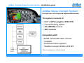
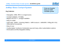
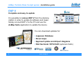
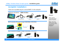
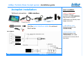
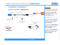
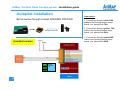
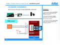
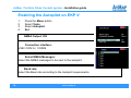
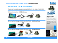
AvMap Portable Glass Cockpit System Installation guide EKPV, Cockpit Docking Station, instruments and accessories. Ver.6.0 This presentation contains confidential information and it is property of AvMap Srl. All images are for illustrative purpose only; described products and features are subject to change without notice AvMap Portable Glass Cockpit system - Installation guide Contents: 1. AvMap Glass Cockpit System presentation 2. AvMap EKP V presentation 3. Cockpit Cradle kit installation 4. Cockpit Docking Station installation 5. GPS receiver installation 6. Autopilot installation 7. ZAON PCAS XRX installation 8. A2 ADAHRS installation 9. EVS installation 10. Device Manager 2 www.avmap.it AvMap Portable Glass Cockpit system - Installation guide AvMap Glass Cockpit System For light-sport, ultra-light and experimental aircrafts The system consists of: 1. EKP V GPS navigator, EFB, PFD 2. Cockpit Docking Station 3. A2 ADAHRS module 4. GPS receiver Compatible with: Through Cockpit Docking Station 3 battery ZAON PCAS XRX traffic receiver Autopilot Enhanced Vision systems Weather receiver WxWorx XM WX* * Service available only in North America www.avmap.it AvMap Portable Glass Cockpit system - Installation guide AvMap Glass Cockpit System Key features 9 Only one Supplier 9 Easy to install 9 Scalable system Navigation, EFB, PFD in a single device Cockpit installed + Portable Bright LCD TFT 7”, sunlight readable Easy to install Ultra Light : EKPV + Docking Station + GPS receiver + ADAHRS = 859g (30.3 Oz) Offering full Connectivity Easy to use Customizable: Vertical or Horizontal view and many other customization options Removable and Rechargeable battery 4 www.avmap.it AvMap Portable Glass Cockpit system - Installation guide Contents: 1. AvMap Glass Cockpit System presentation 2. AvMap EKP V presentation 3. Cockpit Cradle kit installation 4. Cockpit Docking Station installation 5. GPS receiver installation 6. Autopilot installation 7. ZAON PCAS XRX installation 8. A2 ADAHRS installation 9. EVS installation 10. Device Manager 5 www.avmap.it AvMap Portable Glass Cockpit system - Installation guide EKP V: the core of your integrated Glass Cockpit System AvMap EKP V redefines the role of the GPS inside the cockpit. EKP V is intended to be both a cockpit-installed instrument and a portable device. The wide and bright 7” LCD becomes multifunctional and capable to display several data useful for your flight. 6 www.avmap.it AvMap Portable Glass Cockpit system - Installation guide EKP V Compact, light yet fully featured A ultra bright 7” display only 0.8” thick. EKP V is slim and light, yet very powerful: with built in u-blox 6 GPS receiver, removable battery and speakers. Built-in and portable at the same time! EKP V is intended to be both a cockpit-installed on board-instrument and a portable device. 7 www.avmap.it AvMap Portable Glass Cockpit system - Installation guide EKP V Complete and easy to update It is possible to remove EKP V from the docking station in order to update its software and maps. Simply connect EKP V to the PC and use the AvMap Suite application to update the device. You can download updates for: Jeppesen Database Street maps Approach plates and Airport diagrams FAA Sectional / DFS ICAO (optional charts) 8 www.avmap.it AvMap Portable Glass Cockpit system - Installation guide Integrating EKP V into the panel EKP V can be used both as a portable knee pad and be panel mounted in 2 ways: Cockpit Cradle Kit BASIC INTEGRATION Power supply and connection to the external GPS receiver. Cockpit Docking Station ADVANCED CONNECTIVITY The hub for all the electric connections. It allows connecting to EKP V multiple instruments at the same time: • GPS receiver • Autopilot • Traffic Receiver PCAS ZAON XRX • ADAHRS • Enhanced vision systems. 9 www.avmap.it In both cases, it is possible to remove the EKP V from the plane for home playing, theft prevention, training school briefing and debriefing, etc. AvMap Portable Glass Cockpit system - Installation guide Connections EKP V - portable COCKPIT CRADLE KIT Instrument / accessory COCKPIT DOCKING STATION Possible simultaneous Connections Power supply GPS Receiver 1 USB connection choose among GPS receiver or other instruments. ADAHRS 1 USB connection in alternative to the GPS receiver Autopilot 1 USB connection in alternative to the GPS receiver CAS 1 USB connection in alternative to the GPS receiver . EVS Enhanced Vision System Weather receiver* *Service available in North America only Others… 10 1 USB connection in alternative to the GPS receiver 1 USB connection in alternative to the GPS receiver www.avmap.it 4 USB connection, 2 serial connections, audio input and output, video input. AvMap Portable Glass Cockpit system - Installation guide Panel mounting EKP V EKP V can be installed in Vertical or Horizontal mode. 11 www.avmap.it AvMap Portable Glass Cockpit system - Installation guide Contents: 1. AvMap Glass Cockpit System presentation 2. AvMap EKP V presentation 3. Cockpit Cradle kit installation 4. Cockpit Docking Station installation 5. GPS receiver installation 6. Autopilot installation 7. ZAON PCAS XRX installation 8. A2 ADAHRS installation 9. EVS installation 10. Device Manager 12 www.avmap.it AvMap Portable Glass Cockpit system - Installation guide Cockpit Cradle kit: basic integration The Cockpit Cradle Kits is recommended for pilots who want their EKP V conveniently integrated into their cockpit, but do not need advanced connectivity to other on board systems. It feeds EKP V and connects it to the GPS receiver. 13 www.avmap.it AvMap Portable Glass Cockpit system - Installation guide Cockpit Cradle kit installation Content of the box: • Cockpit Cradle • Flush mount + cables fastening mount • GPS receiver (USB interface) • Protective cover • Power supply cable • screws and template jig Rear view USB: GPS receiver connection Front view The internal EKP V battery powers the USB port in order to ensure availability of GPS even in case of aircraft electrical power failure. 3A fuse to be connected to the power supply Safety switch: disables the power supply when the device is not docked. Male Pogo Pin connector For EKP V Power supply cable to be connected to the aircraft electric system. The Cockpit Cradle must be fed with 10-35 VDC (28 W max) voltage. 14 www.avmap.it AvMap Portable Glass Cockpit system - Installation guide Cockpit Cradle kit Installation 1. Drill the cockpit with the help of the template Jig. (Dimensions: 165.4 x 106.8 mm) 2. Connect the power supply cable to the aircraft electric system. 165,4 3. Connect the GPS receiver to the USB port on the back of the cradle and secure the cable fastening the wire lock. 4. Insert the Cradle in the hole and fix it using the screws and the metal parts provided. 15 www.avmap.it AvMap Portable Glass Cockpit system - Installation guide Cockpit Cradle kit installation 5. Re-calibrate the on-board compass, make sure that all on-board instruments and systems perform as expected and verify the presence of heat sources close to the Cradle. 6. Finally, fasten the wires in the back of the Cradle to avoid vibrations and stress on the connections. How to dock the EKP V: 1. Insert the EKP V in the Cradle from the Pogo Pin connector side taking care of properly block the hook on the right. 2. then press the opposite part to insert completely the navigator inside the Cradle. 3. Securely fix the EKP V with the safety hook on the left side. Once docked the EKP V will power on automatically. 16 www.avmap.it AvMap Portable Glass Cockpit system - Installation guide Contents: 1. AvMap Glass Cockpit System presentation 2. AvMap EKP V presentation 3. Cockpit Cradle kit installation 4. Cockpit Docking Station installation 5. GPS receiver installation 6. Autopilot installation 7. ZAON PCAS XRX installation 8. A2 ADAHRS installation 9. EVS installation 10. Device Manager 17 www.avmap.it AvMap Portable Glass Cockpit system - Installation guide GPS ADARHS Autopilot CAS Video Camera Cockpit Docking Station: advanced connectivity Thanks to the special Docking Station EKP V can connect to several on-board devices at the same time such as: third party autopilot, XM WX Weather*, CAS, A2 ADAHRS, Video Cameras etc. * Service available in North America only. 18 www.avmap.it AvMap Portable Glass Cockpit system - Installation guide Cockpit Docking Station - versions standard OEM Standard Version (UX0DS100AM) DB 15 adapter with clamp board 19 OEM Version (UX0DS200AM) DB 15 connector for direct soldering www.avmap.it AvMap Portable Glass Cockpit system - Installation guide Cockpit Docking Station Content of the box: • Cockpit Docking Station • Flush mount + cables fastening mount • GPS receiver (USB interface) • Plastic protective cover • Power supply cable • screws and template jig Connections: • 4x USB 2.0 • 2x Serial ports (1x RS-232, 1x TTL levels) • Audio IN / Audio OUT • Video IN (PAL o NTSC) • Antenna GPS receiver • Power cable: 10 - 35 VDC (28W max) 20 www.avmap.it AvMap Portable Glass Cockpit system - Installation guide Cockpit Docking Station Front view A. Male Pogo Pin connector For EKP V B. 3A fuse to be connected to the power supply C. Safety switch: disables the power supply when the device is not docked. 21 www.avmap.it AvMap Portable Glass Cockpit system - Installation guide Cockpit Docking Station: connections Serial free wires Connections Connections D Battery powered USB Port: backup power provided by the EKP V internal battery. E Normal USB Ports: powered by the aircraft electrical system. F DB 15 direct soldering connector (OEM version only). G Wire clamp connector (Standard version only). H Cable locking bar. Power supply Autopilot USB Connections OEM version GPS receiver Max-Viz-600 A2 ADAHRS ZAON PCAS XRX Serial Interface cable ZAON PCAS XRX standard version USB-Serial cable 22 www.avmap.it AvMap Portable Glass Cockpit system - Installation guide Cockpit Docking Station: serial connections Standard version Standard (UX0DS100AM) DB 15 adaptor with clamp OEM (UX0DS200AM) DB 15 connector for direct soldiering Pin # Signal PWR - External Power supply input (10-35Vdc) 1 PWR - 9 PWR + External Power supply input (10-35Vdc) Push to talk 2 PTT Push to talk PWR + GND 10 PTT AGND 3 Video Input V.IN A-IN Audio input AGND A.OUT Audio Output AGND GND RXA Serial interface “A” RS232 polarity and levels TXA GND RXB Serial interface “B” RS232 polarity and levels TXB 23 Signal PIN label www.avmap.it GND AGND 11 V.IN 4 A.IN 5 AGND 5 AGND 12 A.OUT 6 RXA 13 GND 14 TXA 7 GND 15 RXB 8 TXB Video Input Audio input Audio Output Serial interface “A” RS232 polarity and levels Serial interface “B” RS232 polarity and levels OEM version AvMap Portable Glass Cockpit system - Installation guide Cockpit Docking Station installation 1. Drill the cockpit with the help of the template Jig. (Dimensions: 165.4 x 106.8 mm) 2. Connect and secure the included DB-15 interface (direct soldering or clamp board, depending on the CDS version) on the back of the CDS 3. Connect the power supply cable to the aircraft electric system. (direct soldering or clamp board, depending on the CDS version) on the back of the CDS 4. Connect the GPS receiver to the USB port on the back of the cradle and secure the cable fastening the wire lock. 5. Install the docking station in the cockpit hole and secure it with the flush mount. Push the bracket in the center and flex it until it is possible to lock it with the provided nuts. 6. Fasten and secure the wires to the back of the CDS, to avoid vibrations or mechanical OEM Version Standard Version stress on the connections. 24 www.avmap.it AvMap Portable Glass Cockpit system - Installation guide Connections Instruments / accessories GPS receiver ADAHRS COCKPIT DOCKING STATION Interface Extra cables needed Notes USB 1 (powered by internal battery) - 4 simultaneous USB connections USB - 4 simultaneous USB connections Free wires (direct soldering or clamp board) to A / B serial - 2 simultaneous serial connections Autopilot 4 simultaneous USB connections USB USB-Serial cable Serial Interface cable Free wires (direct soldering or clamp board) to A / B serial CAS PCAS XRX interface cable USB USB-Serial cable EVS enhanced vision systems Weather receiver* *Service available in North America only Others 25 2 simultaneous serial connections 4 simultaneous USB connections Free wires (direct soldering or clamp board) (to Video and Audio input) - USB / Free wires (direct soldering or clamp board) to A / B serial - 4 simultaneous USB connections USB, serial audio input and output, www.avmap.it video input. - 4 USB and 2 serial simultaneous connections AvMap Portable Glass Cockpit system - Installation guide EKP V connections Direct connections to portable EKP V: 1 USB at your choice Instrument / accessory Interface Extra cables needed Notes 1 USB connection to be used for GPS or another instrument GPS receiver USB - ADAHRS USB - Autopilot USB USB-Serial cable CAS Serial Interface cable USB-Serial cable Weather receiver* *Service available in North America only 26 - www.avmap.it 1 USB connection in alternative to GPS receiver 1 USB connection in alternative to GPS receiver USB USB 1 USB connection in alternative to GPS receiver 1 USB connection in alternative to GPS receiver AvMap Portable Glass Cockpit system - Installation guide Contents: 1. AvMap Glass Cockpit System presentation 2. AvMap EKP V presentation 3. Cockpit Cradle kit installation 4. Cockpit Docking Station installation 5. GPS receiver installation 6. Autopilot installation 7. ZAON PCAS XRX installation 8. A2 ADAHRS installation 9. EVS installation 10. Device Manager 27 www.avmap.it AvMap Portable Glass Cockpit system - Installation guide GPS receiver installation Instructions: 1) Direct connection – USB interface 1.Plug the EKP V power cable into the cigarette lighter socket, and the Hirose connector to the EKP V. 2. Connect the USB female connector of the EKP V power cable to the male USB connector of the GPS receiver. EKP V power cable Included in the box Instructions: 2) Connection through DOCKING STATION – USB interface Connect the GPS receiver USB female connector to any USB port of the Cockpit Docking Station. N.B. The first USB port on the right is powered by the EKP V internal battery. 28 www.avmap.it AvMap Portable Glass Cockpit system - Installation guide Enabling the external GPS 1. 2. 3. 29 Press the Menu button Select Tools Set External GPS as: ON www.avmap.it AvMap Portable Glass Cockpit system - Installation guide Contents: 1. AvMap Glass Cockpit System presentation 2. AvMap EKP V presentation 3. Cockpit Cradle kit installation 4. Cockpit Docking Station installation 5. GPS receiver installation 6. Autopilot installation 7. ZAON PCAS XRX installation 8. A2 ADAHRS installation 9. EVS installation 10. Device Manager 30 www.avmap.it AvMap Portable Glass Cockpit system - Installation guide Autopilot installation There are 3 possible ways to connect EKP V to the autopilot 1) Direct connection – USB interface Autopilot EKP power cable USB – Serial cable Included in the box Optional Serial Interface cable Optional 2) Connection through Cockpit DOCKING STATION Free wires 3) Connection through Cockpit DOCKING STATION 31 USB – Serial cable Serial Interface cable Optional Optional www.avmap.it EKP V can be connected to third parties Autopilots. EKP V can send NMEA strings with info relative to GPS position and navigation. AvMap Portable Glass Cockpit system - Installation guide Autopilot installation WHAT IS NEEDED: 1) Direct connection - USB interface EKP V Power cable USB – Serial Serial Interface cable Included in the box Optional Optional Cut the serial interface cable to uncover the 4 wires. DB 9 FEMALE 32 • EKP V Power cable Included in the box (product code CBYAMG0500) With double connector: USB female and Hirose power supply connector. • USB-SERIAL cable Optional (product code UX0US100AM) • Serial Interface cable Optional (product code CBDJNG0400) the cable must be cut to uncover the 4 free wires. www.avmap.it AvMap Portable Glass Cockpit system - Installation guide Autopilot installation Instructions: 1) Direct Connection - USB interface 1.Plug the EKP V Power cable into the cigarette lighter socket. 2. Connect the female USB connector of the EKP V Power cable to the USB-Serial cable male USB connector. 3. Cut the serial interface cable. USB – Serial cable Optional Serial Interface cable Optional 4. Connect the white RXA wire of the serial interface cable to the Autopilot DB connector labeled as TXA. 5. Connect the yellow TXA wire of the serial interface cable to the Autopilot DB connector labeled as RXA. 6. Connect the black GND wire of the serial interface cable to the Autopilot DB connector labeled as GND. EKP V power cable Included in the box 33 www.avmap.it AvMap Portable Glass Cockpit system - Installation guide Autopilot installation Instructions: 2) Connection through Cockpit DOCKING STATION Autopilot free wires 2. Connect the Autopilot yellow TXA cable to the Docking Station clamp board: pin labeled with RXA. 3. Connect the Autopilot black GND cable to the Docking Station clamp board: pin labeled with GND. standard version GND RXA Serial interface “A” TXA 34 1. Connect the Autopilot white RXA cable to the Docking Station clamp board: pin labeled with TXA. www.avmap.it AvMap Portable Glass Cockpit system - Installation guide Autopilot Installation 2) Connection through Cockpit DOCKING STATION Instructions: 1. Connect the Autopilot white RXA cable to the Docking Station DB connector: pin 14. Autopilot free wires 2. Connect the Autopilot yellow TXA cable to the Docking Station DB connector: pin 6. 3. Connect the Autopilot black GND cable to the Docking Station DB connector: pin 13. OEM version 35 6 RXA 13 GND 14 TXA www.avmap.it Serial interface “A” AvMap Portable Glass Cockpit system - Installation guide Enabling the Autopilot on EKP V 1. 2. 3. 4. Press the Menu button Select Tools Select Autopilot Set: NMEA Output: ON Connection interface: USB / COM A / COM B Select NMEA Messages: Select the NMEA messages to be sent to the autopilot. Baud rate: Select the Baud rate according to the Autopilot requirements. 36 www.avmap.it AvMap Portable Glass Cockpit system - Installation guide Setting the communication with the Autopilot 1. Press the Menu button 2. Select Tools 3. Select Autopilot 4. Select NMEA Messages to choose which sentences to send to the Autopilot: APA: Autopilot sentence (obsolete) APB: Heading/Track Controller (Autopilot Sentence “B”) GGA: Global Positioning system fix data GSA: GNSS DOP and Active Satellites GSV: GNSS Satellites in View RMB: Recommended minimum navigation information RMC: Recommended minimum specific GNSS data XTE: Cross-Track Error 37 www.avmap.it AvMap Portable Glass Cockpit system - Installation guide Contents: 1. AvMap Glass Cockpit System presentation 2. AvMap EKP V presentation 3. Cockpit Cradle kit installation 4. Cockpit Docking Station installation 5. GPS receiver installation 6. Autopilot installation 7. ZAON PCAS XRX installation 8. A2 ADAHRS installation 9. EVS installation 10. Device Manager 38 www.avmap.it AvMap Portable Glass Cockpit system - Installation guide PCAS XRX ZAON installation There are 3 possible ways to connect EKP V to the Zaon PCAS XRX: 1) Direct connection - USB interface EKP V power cable USB – Serial cable Included in the box Optional 2) Connection through DOCKING STATION - USB interface USB – Serial cable Optional 3) Connection through DOCKING STATION - Serial interface PCAS XRX interface cable Optional 39 www.avmap.it ZAON PCAS XRX Traffic receiver: If connected to EKP V, the detected aircraft are displayed on the 7” LCD with relative altitude and distance. AvMap Portable Glass Cockpit system - Installation guide ZAON PCAS XRX installation 1) Direct connection – USB interface WHAT IS NEEDED: • EKP V Power cable Included in the box (product code CBYAMG0500) With double connector: USB female and Hirose power supply connector. EKP V power cable USB – Serial cable Included in the box Optional CBYAMG0500 UX0US100AM • USB-SERIAL cable Optional (product code UX0US100AM) Instructions: 1. Plug the EKP V Power cable into the cigarette lighter socket. 2. Connect the female USB connector of the EKP V Power cable to the USBSerial cable male USB connector. 3. Connect the USB-Serial cable to the PCAS XRX ZAON. 40 www.avmap.it AvMap Portable Glass Cockpit system - Installation guide ZAON PCAS XRX Installation 2) Connection through DOCKING STATION – USB interface WHAT IS NEEDED: USB-SERIAL cable Optional (product code UX0US100AM) Instructions: USB – Serial cable Optional UX0US100AM 1. Plug the USB connector of the USBSerial cable to any USB port of the Cockpit Docking Station. N.B. The first USB port on the left is powered from the EKP V internal battery. 2. Plug the serial connector of the USBSerial cable to PCAS XRX ZAON. 41 www.avmap.it AvMap Portable Glass Cockpit system - Installation guide ZAON PCAS XRX installation 3) Connection through DOCKING STATION – Serial interface PCAS XRX interface cable Optional CBDJMG0400 Cut the PCAS XRX interface cable to uncover the 4 free wires. 42 www.avmap.it WHAT IS NEEDED: PCAS XRX interface cable Optional (product code CBDJMG0400) The cable must be cut to uncover the 4 free wires to be connected to the Docking Station. AvMap Portable Glass Cockpit system - Installation guide ZAON PCAS XRX installation 3) Connection through DOCKING STATION – Serial interface WHAT IS NEEDED: PCAS XRX interface cable Optional (product code CBDJMG0400) The cable must be cut to uncover the 4 free wires to connect to the Docking Station. PCAS XRX interface cable Optional CBDJMG0400 Instructions: 1.Connect the white RXA of the PCAS XRX interface cable to the Docking Station clamp board, PIN labeled as RXA. Standard version 2. Connect the yellow TXA of the PCAS XRX interface cable to the Docking Station clamp board, PIN labeled as TXA. 3. Connect the black GND of the PCAS XRX interface cable to the Docking Station clamp board, PIN labeled as GND. RXA GND TXA 43 Serial interface “A” www.avmap.it 4. Plug the serial connector of the PCAS XRX interface cable to the Zaon PCAS XRX. AvMap Portable Glass Cockpit system - Installation guide ZAON PCAS XRX installation WHAT IS NEEDED: 3) Connection through DOCKING STATION – Serial interface PCAS XRX interface cable Optional CBDJMG0400 OEM version 6 RXA 13 GND 14 TXA Serial interface “A” 7 GND 15 RXB 8 TXB Serial interface “B” PCAS XRX interface cable Optional (product code CBDJMG0400) The cable must be cut to uncover the 4 free wires to connect to the Docking Station. Instructions: 1. Connect the white RXA of the PCAS XRX interface cable to the Docking Station DB 15 connector, PIN N.6 (or N.7 ) 2. Connect the yellow TXA of the PCAS XRX interface cable to the Docking Station DB 15 connector, PIN N. 14. (or N.8) 3. Connect the black GND of the PCAS XRX interface cable to the Docking Station DB 15 connector, PIN N. 13. (or N.15 ) 4. Plug the serial connector of the PCAS XRX interface cable to the Zaon PCAS XRX. 44 www.avmap.it AvMap Portable Glass Cockpit system - Installation guide Enabling the ZAON PCAS XRX on EKP V 1. Press the Menu button 2. Select Tools 3. Select Traffic 4. Set: DATA reception: ON Connection interface: USB / COM A / COM B Range alert: select the action range 6 / 3 / 1.5 NM Aircraft type: choose the type of aircraft ( read the ZAON PCAS XRX manual for further info). Setting the ZAON PCAS XRX On the ZAON PCAS XRX, open the COM menu and select Profile 1. 45 www.avmap.it AvMap Portable Glass Cockpit system - Installation guide Traffic as displayed on EKP V Once EKP V is connected to the ZAON PCAS XRX and that both devices have been set, the traffic data are displayed on the EKP V map. 46 www.avmap.it AvMap Portable Glass Cockpit system - Installation guide Contents: 1. AvMap Glass Cockpit System presentation 2. AvMap EKP V presentation 3. Cockpit Cradle kit installation 4. Cockpit Docking Station installation 5. GPS receiver installation 6. Autopilot installation 7. ZAON PCAS XRX installation 8. A2 ADAHRS installation 9. EVS installation 10. Device Manager 47 www.avmap.it AvMap Portable Glass Cockpit system - Installation guide A2 ADAHRS: Turns EKP V into an EFIS ■ The EKP V turns into a full-featured Primary Flight Display when connected to AvMap's A2 ADAHRS module. The AvMap A2 ADAHRS is a compact fixed-install module providing attitude, heading, altitude and airspeed data to the system. ■ A2 ADAHRS contains solid-state gyros, accelerometers, magnetic field sensors and air data sensors; it should be connected to the aircraft pitot-static system, in order to take full advantage of its functionality. ■ The small and light weighted ADAHRS module easily fits into the aircraft as it can be installed in any orientation (a proper calibration procedure must be performed). It is suggested to install the A2 aligned with the aircraft longitudinal axis, as it simplifies the attitude calibration process. 48 www.avmap.it AvMap Portable Glass Cockpit system - Installation guide A2 ADAHRS - specifications • Dimensions: 2.48” x 2.28” x 0.98” • Weight: < 1.8 Oz ( < 50 g) • Temperature Range: -40°F to +185°F • 3-axis gyros, accelerometers and magnetometers • Acceleration range (3 axis) +/- 8 g • Rotation range +/- 1600 deg/s • Air data sensors 0-250 kts; -3000, + 44000 ft) • UAV Navigation® motion processor • Advanced data fusion capability • USB interface (1,5 m cable) • Guided calibration procedure Content of the box: ADAHRS module 49 www.avmap.it AvMap Portable Glass Cockpit system - Installation guide A2 ADAHRS installation 1. Choosing the position • Near the pitot and static lines • In a location clear of strong magnetic or electromagnetic disturbances as much as possible. • Avoid installing the A2 ADAHRS near electronic equipment (other digital EFIS, radios, transponders, etc), AC or variable DC cables, alternators, electrical motors, ferrous materials, etc. In such cases the proper behavior of the compass is not guaranteed (i.e. the compass may be crossed as “out of order” or may give erroneous indications). Hint: Use a hand-held compass to verify the magnetic disturbance in the area selected for installation. If the needle shows relevant changes or unstable indication, the location is not suitable for installation. Make sure to perform this test with all on-board electronic devices switched ON. 50 www.avmap.it AvMap Portable Glass Cockpit system - Installation guide A2 ADAHRS installation 2. Orientation Scenario A. No calibration needed. Scenario B. A2 ADAHRS is aligned with the aircraft longitudinal axis, is not aligned with straight & level flight attitude but pitch and roll offsets are present: a Horizon Alignment procedure is required. Scenario C. A2 ADAHRS is not aligned with aircraft longitudinal axis, nor with straight & level flight attitude: Full Attitude Calibration procedure is required. 51 www.avmap.it AvMap Portable Glass Cockpit system - Installation guide Enabling the A2 ADAHRS on the EKP V 1. Press the Menu button 2. Select Tools 3. Select EFIS 4. Set: Data reception: ON Full attitude calibration Procedure to be performed on the ground to determine the offset in pitch, roll and yaw between A2 installation attitude and the aircraft. Compass calibration Procedure to be performed in-flight to compensate magnetic disturbances the A2 is subject to. Horizon alignment Procedure to be performed on the ground to compensate only pitch/roll offset between the A2 and the aircraft axis. Reset Calibration Aircraft Profile: choose the type of aircraft. 52 www.avmap.it AvMap Portable Glass Cockpit system - Installation guide Calibrating A2 ADAHRS Horizon Alignment Press MENU > STRUMENTI > EFIS > Horizon Alignment. 1. Make sure the aircraft is in straight and level flight attitude 2. Press the joystick to record a sample of pitch and roll angles Full Attitude Calibration Press MENU > STRUMENTI > EFIS > Full Attitude Calibration. 1. Select if the maneuver will be pitch up or down. For tricycle aircraft the pitch up maneuver can be performed by pushing the tail (pitch up), while tail draggers will execute a pitch down maneuver by raising the tail. 2. Reset A2 ADAHRS calibration data; select Start. Wait until the reset phase is completed. 3. Set the aircraft in level and straight flight attitude by using jacks or blocks (or by asking a friend to push or lift the tail and hold). Press ENTER (joystick click) to record the sample in level & straight flight. 4. Set the aircraft in a pitch up (or down) attitude and press ENTER to record the pitch up/down sample. WARNING: be very careful not to change the aircraft heading while performing the pitch up /down maneuver. 5. Set values to A2 by pressing ENTER. Wait a few minutes for the sensor to stabilize and realign. If pitch and roll after a few minutes are still not aligned fine-tune pitch and roll offset by executing a Horizon Alignment procedure. 53 www.avmap.it AvMap Portable Glass Cockpit system - Installation guide Calibrating A2 ADAHRS on EKP V Compass calibration and test flight ATTENTION: the magnetometer calibration data is invalidated after every attitude calibration procedure (full attitude calibration and horizon alignment). Make sure to properly calibrate attitude before proceeding with Compass Calibration The Compass Calibration procedure must be executed in-flight and requires to steer the aircraft in 4 directions and execute some pitch up/down maneuvers. The total duration for this procedure is about 4 minutes. Press MENU > TOOLS > EFIS > Compass Calibration. The screen switches to Primary Flight Display mode, where a flight director (a magenta frame) shows the maneuvers to perform. Follow the magenta frame until the procedure is finished. 54 www.avmap.it AvMap Portable Glass Cockpit system - Installation guide Calibrating A2 ADAHRS on the EKP V Compass calibration and test flight Assuming that the calibration is started with the aircraft heading North, the steps required are: 1. Maintaining heading 000° execute: pitch up + 20°, back to straight flight and then pitch down -20° 2. Turn left to heading 270° by performing a standard rate turn (the proper bank will be shown by the flight director). The target heading for each step is shown as a magenta reference inside the heading tape. 3. Execute pitch up/down maneuvers as described in step #1 4. Repeat steps #2 and #3 for headings 180° and 090°, until reaching again the original heading. 5. At the end of a successful calibration procedures the compass instruments is enabled (i.e. red cross removed) and the HSI instrument correctly shows AHRS as data source, meaning that magnetic compass data are now available to the EFIS system. Note: it’s not required to start the procedure heading north. Any starting direction is acceptable. Note: If the calibration fails or the compass indicator is not enabled, repeat the calibration procedure. If several calibration attempts fails review the installation location of the A2. Magnetic disturbance could be too high in the selected area. 55 www.avmap.it AvMap Portable Glass Cockpit system - Installation guide Contents: 1. AvMap Glass Cockpit System presentation 2. AvMap EKP V presentation 3. Cockpit Cradle kit installation 4. Cockpit Docking Station installation 5. GPS receiver installation 6. Autopilot installation 7. ZAON PCAS XRX installation 8. A2 ADAHRS installation 9. EVS installation 10. Device Manager 56 www.avmap.it AvMap Portable Glass Cockpit system - Installation guide EVS Astronics Max-Viz-600 Installation Connection through Cockpit DOCKING STATION Max Viz free wires (video input) Standard version Astronics Max-Viz-600 Enhanced Vision System: an advanced infrared camera that improves the Pilot’s situational awareness. It can be connected to the EKP V’s 7” LCD. OEM version Instructions: AGND 1. Connect the Max Viz 600 Video GND cable to the clamp board / BD connector of the Docking Station, to the pin labeled as AGND / N.3 Video Input V.IN 3 11 57 AGND V.IN www.avmap.it Video Input 2. Connect the Max Viz 600 Video Out cable to the clamp board / BD connector of the Docking Station, to the pin labeled as V.IN / N.11 AvMap Portable Glass Cockpit system - Installation guide Enabling the video input on EKP V 1. Press the Menu button 2. Select Tools 3. Select Video IN 4. Select Show Video to view it on the EKP V display. 5. Adjust saturation, contrast, brightness and shade. the video from the camera / EVS can be activated setting this option for the configurable button F1. 58 www.avmap.it AvMap Portable Glass Cockpit system - Installation guide Contents: 1. AvMap Glass Cockpit System presentation 2. AvMap EKP V presentation 3. Cockpit Cradle kit installation 4. Cockpit Docking Station installation 5. GPS receiver installation 6. Autopilot installation 7. ZAON PCAS XRX installation 8. A2 ADAHRS installation 9. EVS installation 10. Device Manager 59 www.avmap.it AvMap Portable Glass Cockpit system - Installation guide GPS Device Manager on EKP V The device manager page shows which instruments are connected to EKP V and if the corresponding application are enabled. 1. Press the Menu button CAS 2. Select Tools 3. Select Dev. Manager 60 www.avmap.it ADARHS Autopilota Video Camera