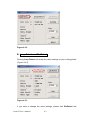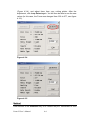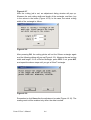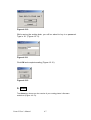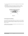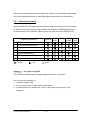
1
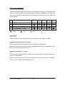
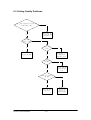
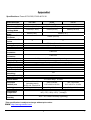
Puma II users manual Contents Important information …………………………………………..…….. Quick installation guide ………………………………………….…… About cutting tool ………………………………………….…………. Checking Supplied items …………………………………….……….. I II III IV Chapter 1. Parts Names and Functions ………………………….……. 1.1 Front view …………………………………………………… 1.2 Back view with stand ………………………………… …….. 1.3 Side view …………………………………………………….. 1.4 Control Panel ………………………………………………… Chapter 2. Setup …………………………………….………………… 1-1 1-1 1-2 1-3 1-4 2-1 2.1 Setting up …………………………………………………….. 2.2 Stands and media support system installation……………….. 2.3 Power and cable connections ………………………………… 2.4 Blade installation ……………………………………………. 2.5 Media loading ……………………………………………….. 2.6 Tracking performance ……………………………………….. 2.7 Dip switch setting ……………………………………………. 2.8 Power on …………………………………………………….. 2.9 On/Off line key ……………………………………………… 2.10 Pause key …………………………………………………… 2.11 Repeat key ………………………………………………….. 2.12 Data clear key ………………………………………………. 2.13 Origin setting ………………………………………………. 2.14 Cut test ……………………………………………………… 2.15 When completing the cutting job …………………………… Chapter 3 Connecting cutting plotter …………………………………. 3.1 Universal serial bus ………………………………………… 3.2 Parallel transmission ……………………………………….. 3.3 Serial transmission …………………………………………. Chapter 4 Virtual LCD ………………………………………………… 4.1 Installation ………………………………………………….. 4.2 Before usingVLCD …………………………………………. 4.3 Functions of VLCD ……………………………………………. Chapter 5 Basic Maintenance ………………………………………… 2-1 2-2 2-5 2-6 2-9 2-15 2-16 2-18 2-19 2-19 2-19 2-20 2-20 2-21 2-23 3-1 3-1 3-2 3-2 4-1 4-1 4-1 4-2 5-1 Puma II users manual 5.1 Cleaning the cutting plotter ………………………………… 5.2 Clearning the grid drum…………………………………….. 5.3 Clearning the pinch rollers …………………………………. Chapter 6 Troubleshooting ………………………………………….… 6.1 If the cutting plotter cannot operate ………………………… 6.2 Light indicators …………………………………………….. 6.3 Cutting quality problem…………………………………….. 5-1 5-1 5-2 6-1 6-1 6-1 6-5 Appendix: 1. Specifications of Puma II ………………………………………….. 2. Specifications of GCC blade ………………………………………. a b Puma II users manual IMPORTANT INFORMATION Thanks for your purchasing of our SignPal Puma II series cutting plotters. For your safety and optimize the performance of the Puma II, please read user manual completely and keep it in a correct location. PRECAUTIONS IN USE For safety’s sake, please always hold the cutter firmly from the bottom when moving it. Please hold from the bottom. Do not shake or drop the blade holder, blade tip maybe fly out. During operation, keep away from any moving parts of the cutter (such as the carriage, drums). Also be careful that clothing and hair do not be caught. Connect the power cable to a grounded outlet. Always use the accessory power cable that is provided. Do not wire the power cable so that it becomes bent or caught between objects. Do not connect the power cable to branch outlet to which other machines are also connected, or use an extension cable. There is danger of overheating and of mis-operation of the machine. Keep the blade away from children. Always put the pinch rollers within position of the white marks. I QUICK MENU 1. Power ON. (The POWER LED lights on) 2. Note: Make sure the level is up before placing the media on the plotter. Place the media and pull the level to lower down the pinch rollers (must be sure the pinch rollers are position above the grid drums, that is, within the white marks). 3. Puma II will take about 10 sec to initialize the machine. Then the cutter will size the media automatically according to set of the dip switch (usually the presetting is EDGE media type). 4. Off-line condition – Plotter is not ready to receive data from computer. Press ON/OFF LINE key, the LED above the key turns off. 5. On-line condition - Plotter is ready to receive data from computer. Press ON/OFF LINE key, the LED above the key lights. 6. Change the setting value during cutting. Press PAUSE key, the LED above the key flashes. To continue cutting press ON/OFF LINE key. 7. Terminate the cutting and clear the data in the buffer. Press ON/OFF LINE key or PAUSE key and then press DATA CLEAR key. II About the Tool A generic term refer to the blade that cuts the sheet, the pen that does plotting, and the LED bombsight (option) used for pointing to the reference point. OFFSET is the distance that the blade tip is displaced from the centerline of the blade. Blade Central line Blade tip Offset Protrusion Length of the Blade Thickness of the film (t1) Protrusion length of the blade Thickness of the base paper (t 2) Length of protrusion = t1 + t 2/ 2, but for your convenience you may just make it about 0.3~ 0.5 mm beyond the blade holder tip. II Checking Supplied Items 1. Installation CD 2. Printer Cable 3. AC Power Cable 4. RS232 Cable 5. Blade Holder & Fiber – 6. Cutting Strip (Pad) Tip Pen 7. Safe Blade 8. USB Cable 9. Error-Correct & Function Sticker 10 Roll Base 11. Tweezers (only for PII-30/60) Puma II Users manual IV 12.Knife Chapter 1 Parts Names and Functions 1.1 Front View Pinch Roller: Press the Cutting Carriage: This unit performs the cutting media against grid drum during cutting. Control Panel: Consists of 10 control keys and 6 LEDs with the installed blade and pen. Paper Sensor: The Sensor detect the presence of media. Cutting Pad: Provides protection for the blade while the blade is cutting Alignment Ruler: Media can be aligned with the clear guide line marks media back and forth during operation. Platen: The surface for Knife Guide: To cut off holding and supporting the extra media easily media during cutting. along this groove. Figure 1-1 Front view of Puma II Puma II users manual Grid Drum: Moves the 1-1 1-2 Back View of Puma II 132S with stand Roll holder support Stand Roll holder Roll Holder guide bushes Fig 1-2 Back view of Puma II 132S with stand Puma II users manual 1-2 1-3 side view of Puma II 1 2 3 Fig 1-3 Left hand side view of Puma II 4 5 6 7 8 Fig 1-4 Right hand side view of Puma II Left Hand Side (Figure 1-3) 1. AC Power Connector – Used to insert the AC power cord. 2. Fuse – Up to 3 Amp. 3. Power Switch – On when switches to [I]; Off when switches to [O] Right Hand Side (Figure 1-4) 4. USB interface Connector - Used to connect the cutting plotter to a computer through a USB cable. 5. Parallel Interface Connector (Centronics) – Used to connect the cutting plotter to a computer through a parallel interface cable. 6. Pen Force Control Slider – Set the blade force here. 7. Serial Interface Connector (RS-232C) – Used to connect the cutting plotter to a computer through a serial interface cable. 8. Dip Switch - Used for various parameter setting. Puma II users manual 1-3 1.4 Control Panel PAUSE Key – This key can temporarily halt cutting DATA CLEAR Key – CUT TEST Key – To test in progress, and the This key can clear the set value. The CUT ON/OFF LINE LED the data in the buffer TEST LED is on, while flashes. Press ON/OFF memory. doing the cut test. LINE Key can resume cutting. ARROW Key – To move the media or the ON/OFF LINE Key – cutting carriage. This key can connect the cutting plotter and the host computer. The LED ORIGIN SET lights on when press Key – This key ON LINE key., Press sets the original again the ON/OFF point. LINE LED will be off. REPEAT Key – Press this button to repeat the last cutting, and the REPEAT LED turns on. POWER LED – Turn on the power, the POWER LED is on. Puma II users manual ERROR LED – This LED is light up or flashing when an error occurs. Please see Chapter 5 “Troubleshooting” for details of error message. 1-4 Chapter 2 Set Up 2.1 Setting Up CAUTION! At least two or more persons holding the Puma II 132S at its bottom surface on the left and right sides when you unpacking, installing or relocating the cutter. Make sure the power switch is off before installing the cutting plotter. Notice! Choosing a proper place before setting up the cutting plotter Select a proper location which meets the following conditions. The machine can be approached easily from any direction. Keep at least 60 cm space in front and behind the machine. Make sure the cutter is placed on a flat, level and sturdy surface The working temperature should be between 5 and 40℃(41-104oF) in the workshop. The relative humidity should be between 30% and 70% in the workshop. Protecting the machine from dust and strengthen air current. Preventing the machine from direct sunlight. Puma II User’s Guide 2-1 2.2 Stands and Media Support System Installation There are seven steps to assemble stand and media support system. Please follow the procedure: Step 1 Check screws and wrench in the accessory box of stand carton: Items Puma II 60/30 Puma II 132S M6 screws 28 24 M5 L- shape hexagon screw driver 1 1 M6 L- shape hexagon screw driver 1 1 M6 wrench (spanner) 1 1 Step 2 Puma II 60 stand: There are three components to assemble it. Please refer to Figure 2-1. Puma II 132S stand: There are four components to assemble it. Please refer to Figure 2-1-1 and 2-1-2 4 3 1 2 Figure 2-1 Figure 2-1-1 Figure 2-1-2 (Puma II 60) (Puma II 132S) (Puma II 132S) Step 3 Then connect part 3 and H-shape stand. First, position the extension of part 3 into the squares holes on H-stand. Second, insert the screws into the holes besides the squares then tighten them, see Figure 2-2. Puma II User’s Guide 2-2 3 Only Puma II 60 has side screws. Puma II 132S doesn’t has side H-stand screws. Figure 2-2 Third, (For Puma II 132S only) position the stand beam perpendicularly to part 3 and put the screws into the holes and tighten them as Figure 2-2-1. Figure 2-2-1 (Only for Puma II-132S) Step 4 Move the cutting plotter from the carton. Put it on the stand, then Insert the screws into the holes on plotter’s bottom as Figure 2-3. Figure 2-3 Step 5 Insert the roll holder support with the screws into the holes of the stand then tighten them as Figure 2-4. You can decide roll holder support’s position by inserting into Puma II User’s Guide 2-3 different holes. Figure 2-4 Step 6 Place two roll holders into the holes in the roll holder support (Figure 2-5). Figure 2-5 Puma II User’s Guide 2-4 2-3 Power and cable Connection ! Notice Check the plug of the power cord to see if it mates with the wall outlet. If not, please contact with your dealer Be sure that the power to both the computer and the main unit is switched off when connecting the cable ! Warning Connecting the Power Supply Ground the unit with the ground wire. Insert the plug (male) into a grounded power outlet. Insert the other end (female) of power cord into the AC connector of the cutting plotter. Securely connect the power cord, Computer I/O cable and so on so that they will not be unplugged and cause failure during operation. Connect the cable to either the parallel or the serial port. Puma II User’s Guide 2-5 2.4 Blade Installation ! CAUTION Do not touch the tip of the blade with your fingers. ! Notice The blade will affect the cutting quality significantly. If any of the following occurs, which means the blade has reached the end of its life. Please replace with a new blade. 1. The tip of blade is broken. 2. Cutting traces are not as good as they were. 3. Uncut area remains the same even the blade force has been raised significantly. Figure 2-7 is the illustrator of the blade holder. Insert a blade into the bottom of the blade holder and remove the blade by pushing the pin. Be sure to keep your fingers away from the blade tip. Pin Adjustment depth knob Outward ring Figure 2-7 Step1 Install blade (Figure 2-8). Figure 2-8 Puma II User’s Guide 2-6 Step 2 Push the blade to the bottom of the blade holder. (Figure 2-9). Figure 2-9 Step 3 Adjust the blade tip to suitable length by screwing “Blade tip adjustment screw” clockwise or count-clockwise (Figure 2-10). Figure 2-10 Puma II User’s Guide Tips: “The proper length” means the blade’s length is about 0.1mm more than film’s thickness. For example, if the thickness of film is 0.5mm, then blade’s length is properly adjusted to 0.6mm and it can completely cut through the film layer but will not cut though the paper backing (See Figure 2-10). 2-7 Step 4 Insert the blade holder into tool carriage. Please note the outward ring of the holder must put into the grooves of carriage firmly (see Figure 2-11) and lock the grip Figure 2-11 Figure 2-12 Step 5 Use the reverse steps to remove the blade holder. Step 6 Press the push - pin to remove the blade from the blade holder when the blade needs to be replaced. Please refer to Figure 2-9 for reference. Puma II User’s Guide 2-8 2.5 Media Loading 2.5.1 Loading the Sheet Media To load the media properly, please follow the procedures listed below: 1. Pull the lever forward to raise the pinch rollers (Figure 2-13). Figure 2-13 Load your media on the platen and slide it under the pinch rollers from either the front side or the backside. The alignment rulers on the platen extension will help you to adjust the media precisely. Note: Be sure that the media must cover the paper sensors on the platen when loading the media. At least one of the two paper sensors (Fig 1-1) should be covered. Once the media covers the sensor, the cutting plotter will size the media’s width and length automatically. Puma II User’s Guide 2-9 2.5.2 Positioning pinch rollers Then move the pinch rollers manually to the proper position. Be sure the pinch rollers must be positioned above the grid drum. The white marks on the main beam will help you to position pinch rollers easily and correctly. (Figure 2-14). White Marks Figure 2-14 Push the lever backward to lower down the pinch rollers. Turn on the power, the tool carriage will measure the size of the media automatically. And the plotting cutter begins to work. Note: Move the pinch roller by applying force at the rear portion of the pinch roller support. Do not move it by holding its front rubber roller. Figure 2-15 Correct way to move pinch rollers Puma II User’s Guide 2-10 2.5.3 Loading the Roll Media First, put the roll media guide bushes on two roll holders (Figure 2-16). Figure 2-16 Option A (Recommended) Insert the two roll holders into the roll media support set then place the roll media directly between the two roll holders (Figure 2-17). Figure 2-17 Puma II User’s Guide 2-11 Option B (Use the media flanges) 1. Insert a roll media flange at the end of each roll media and tighten the thumbscrew until the roll media is firmly gripped (Figure 2-18). Figure 2-18 2. Then put the roll media on the roll holders. Adjust the position of the roll media ensure that media flanges are able to run in the grooves of media guide bushes. (Figure 2-19) Figure 2-19 Puma II User’s Guide 2-12 3. Loading the media on the platen. After loading the roll media, flatten the media on the platen and hold the front edge of the roll media firmly (Figure 2-20). Figure 2-20 4. Then turn the roll downward to make an equal tension across the media. (Figure 2-21) Figure 2-21 Puma II User’s Guide 2-13 5. Move the pinch rollers to the appraise location and be careful that the pinch rollers must be positioned above the grid drums. 6. Push the lever backward to lower down the pinch rollers. 7. Fixes roll media guide bushes on the roll holder to secure the roll media. 8. Turn on the power switch, and the tool carriage will size the media automatically. Then the cutting plotter is ready to work. 9. Use the reverse steps to remove the media. For the users of Puma PII-30 or PII-60, you can also use the Roll Base to feed a roll media. Please adjust the position of roll base to get a good cutting result. (Figure 2-22) Figure 2-22 Puma II User’s Guide 2-14 2.6 Tracking Performance In order to achieve the best tracking performance for a long plot, we recommend some significant media loading procedures described as follows: 1. If the media length is less than 4 m, leave the margin of 0.5mm~15mm in the left and right edges of the media (see Figure 2-23). 0.5mm-15mm 0.5mm-15mm Pinch roller Pinch roller Figure 2-23 2. If the media length is greater than 4m, leave at least 25mm margin on the left and right edges of the media (see Figure 2-24). >25mm At least 25mm Pinch roller PPinch roller Figure 2-24 Puma II User’s Guide 2-15 2.7 Dip Switch Setting To get a perfect cutting job, you have to choose the proper Dip Switch setting. The table below shows function of each Dip Switch. The cutting plotter will read values of Dip Switches every time when press ON/OFF LINE key. **Dip Switch setting change during on-line condition will not work. You can change the setting by pressing PAUSE key or when the plotter is in off-line condition. The default setting value is as Figure 2-25. 1 2 3 4 5 6 7 8 ON OFF Figure 2-25 Dip Switch SW 1-3 SW-4 SW-5 SW-6 SW-7 SW-8 SW 1-3 Function Offset Value Media Weight Quality Smooth Auto Unroll Media Type : Switch Down Switch Up (Please refer to SW 1-3) Light 0 275 Heavy Draft Fine Enable Disable Enable Disable Edge Single Default Value 0.275 mm Light Media Fine Enable Enable Edge OFFSET SETTING The first three Dip Swtches represent 8 different blade offset values as below: 0.000 0.175 0.250 0.275 0.300 0.500 0.750 1.000 SW-4 : MEDIA WEIGHT (SPEED) The fourth Dip Switch from the left sets the maximum cutting speed. Heavy media has a smaller upper limit. The value of the cutting speed can be changed from the driver When switch to "Heavy media", the maximum cutting speed is set at 300mm/ sec, minimum cutting speed is set at 30mm/sec When switch to "Light media", the maximum cutting speed is set at 600mm/ sec, minimum cutting speed is set at 330mm/sec. Puma II User’s Guide 2-16 SW-5 : QUALITY There is a trade-off between cutting quality and speed, the better the cutting quality, the slower the cutting speed. Fine quality Draft quality SW-6 : SMOOTH Make the curves smoother during cutting. **When cut the small letter, please set smooth disabled to cutting quality smooth setting. Disable the smoothing cut. Enable the smoothing cut. SW-7 : AUTO UNROLL Unroll the heavy media at least 50 cm when the next point of movement is located beyond the unrolled position. As the media type is Single, this function will be disabled. Disable the auto unroll Enable the auto unroll SW-8 : MEDIA TYPE Set the type of the media you use. When using a piece media, set it to “ON”; and set it to “OFF” when using a roll media. Single sheet of media is using. A roll of media is using. Puma II User’s Guide 2-17 2.8 Power On Be sure not to put anything or hands on the platen of the plotter when turning on the power. It may cause injury. Keep long hair away from the grid drum when power is on.. Turn on the power on the left-hand side of the cutting plotter and the POWER LED is on. Notice: It will take about 10 sec to initialize the machine, the cutting plotter is ready to receive data from computer. As bellowing is control panel lights when uses different functions key in normal conditions. POWER ERROR ON/OFF REPEAT DATA CUT LINE CLEAR TEST Function on-line state pause state off-line state repeat data clear cut test origin set = flash Puma II User’s Guide = on = off 2-18 2.9 ON/OFF LINE Key **On - line When the machine is in “ON LINE ” condition. The ON/OFF LINE LED is on. The cutting plotter is ready to receive data from the host computer. At this moment, only “PAUSE” and “ON/OFF LINE” keys are valid. **Change the setting value 1. Press the PAUSE key. Then switch the dip to change the setting value. 2. Press the ON/OFF LINE key to effect new setting and continue cutting. Note : The parameters of dip switch can not be changed while the cutting has started unless pressing the “PAUSE” key. When press the “PAUSE” key, you can change the setting. **Terminate the cutting & clear the data in the buffer 1. Press the ON/OFF LINE or PAUSE key 2. Then press the DATA CLEAR key **Off - line When the machine is in “OFF LINE” condition, the ON/OFF LED turn off. At this moment, you can switch dip setting, make cutting test to adjust blade pressure and set new origin. Press the key again will let the cutting plotter switch back to “ON LINE” condition, and resume the suspended operation. But there might be some data loss during this interruption. 2.10 PAUSE Key The purpose of the “PAUSE” key is to temporarily terminate the motion of the cutter after it started cutting. At this moment, the ON/OFF LINE LED flash; you can change the dips switch setting and the cutting force. It will resume cutting after pressing the ON/OFF LINE key to make the machine in on-line status. 2.11 Repeat Key You can cut your last cutting job at the same position by pressing REPEAT key without setting new origin. If you’re using a thicker media, it is better to use this function to avoid Puma II User’s Guide 2-19 damaging your blade. ** Procedures to repeat cutting job at different position: 1. After cutting finishes, use the ARROW keys to move the tool carriage. Move to your desired position for repeating the cutting job, then press the ORIGIN SET key. The ORIGIN SET LED lights, and new origin point is set. 2. Press the REPEAT key to repeat the cutting job, and the REPEAT LED lights. 2.12 DATA CLEAR Key The purpose of the DATA CLEAR key is to clear the data in the buffer memory. The DATA CLEAR key can only works under pause or off-line condition. When use this function, the DATA CLEAR LED will light. 2.13 Origin Setting Use the ORIGIN SET key to set a new origin at any position in the cutting area where the tool carriage starts to work. Please note new origin setting must be made under the off-line condition. Procedures : 1. After loading the media and lowering down the level, use ARROW keys to move the carriage to the desired location for a new origin. 2. Press ORIGIN SET key and the original point is set. The ORIGIN SET LED lights. Puma II User’s Guide 2-20 2.14 Cut Test Before carrying out actual cutting, it is necessary to perform a cutting test to determine the appropriate cutting force and offset value for your media. The cutting test should be repeated until you get an appropriate cutting condition. Once you finish the cutting test, the new origin is also set to the current tool carriage position. There are two adjustments you should do when perform cutting test. First one is cutting force adjustment; the second one is blade-offset adjustment. Procedures : 1. After sizing the media, press the ON/OFF LINE key to switch to off-line mode. 2. Then use arrow keys to move the tool carriage to the position where you will make cut test. 3. Press the CUT TEST key to make the cutting test. The CUT TEST LED turns on. 2.14.1 Adjust Cutting Force First, move the “Pen Force Control Slider” to the min blade force, then increase the blade force gradually by moving the slider, until an optimum force is obtained to cut through the media. When the cutting test is completed, a square cut out appears. If the square can be easily peel off from the media, the setting of cutting force is appropriate. If not, adjust the tool force again. 2.14.2 Adjust Offset Value The square cut out should appear as one of the follow figure: AA Appropriate offset value BB CC offset too low offset too high Or over-speed Puma II User’s Guide 2-21 If the square appears BB or CC layout, adjust the OFFSET setting (please refer to paragraph SW1-3 OFFSET SETTING; Please also refer to the paragraph “About the tool ” at the beginning of the book to learn the definition of offset.) Note: The new origin will be set at the position of tool carriage after cutting test. Puma II User’s Guide 2-22 2.15 When Completing the Cutting Job After completing the cutting, raise the sheet loading lever, then remove the material. You can also cut off the extra media with the cutter tool along the knife guide (Figure 2-25). Figure 2-25 Puma II User’s Guide 2-23 C Ch haap ptteerr 33 Connecting Cutting Plotters The cutting plotter communicates with a computer through a USB (Universal Serial Bus), Parallel port (Centronics) or a Serial port (RS-232C). This chapter shows you how to connect the cutting plotter to a host computer and how to set up the computer/cutting plotter interconnection. !! Notice: 1. When USB connection is enabled, both parallel port and serial port will be disabled automatically. 2. Please don't plug in USB cable when you install the driver Parallel Interface Serial Interface USB Interface Figure 3-1 3.1 Universal serial bus Puma II build-in USB interface are based on the Universal Serial Bus Specifications Revision 1.1. USB is not available in Windows 95, Windows NT. 3.1.1 USB driver installation Insert “Installation CD”, and then click on “USB driver” to install USB driver. 3.1.2 Connection Plug the cable connector into the Puma II’s USB interface connector. Plug the other end of the cable into the PC’s USB interface connector. 3.1.3 Cutting driver or sign cutting software installation Install Puma II driver or sign cutting software. Puma II Users manual 3-1 3.2 PARALLEL TRANSMISSION 3.2.1 Connecting to the Parallel Port (Centronics) 1. Connect a parallel cable to the cutting plotter and the host computer (Figure3-1). 2. Set up the output port LPT1 or LPT2 from your software package 3. Send the data to your cutting plotter directly. Or, use DOS commands like TYPE or PRINT to output data. 3.3 SERIAL TRANSMISSION 3.3.1 Connecting to the Serial Port (RS-232C) 1. For PC users, please connect the RS-232C cable to the serial connector of the assigned serial port (COM1 or COM2) of your host computer. 2. Set up the communication parameters (Baud Rate, Data Bits/Parity and Stop Bits) to match the setting on the computer. 3.3.2 Transmitting the Data to Plotter There are two options to transmit the data from the computer to the cutting plotter: Option 1 With proper interface settings, the data can be transmitted from your application software package to the cutting plotters directly. Option 2 Most cutting software packages are able to emulate HP-GL or HP-GL/2 commands, therefore, Use DOS commands like TYPE or PRINT to output your file. As long as the file is HP-GL or HP-GL/2 format, the cutting plotter can output the data precisely. For example, a file with PLT extension generated by SignPal software, FlexiSign or SignLab can be transmitted directly to the plotter at the DOS prompt, and then be cut out. Before outputting at the DOS prompt, set up a transmission protocol between your cutting plotter and computer by a DOS command, MODE. Make sure that your PC has the same communication protocol as the cutter. For example: MODE COM2: 9600,N, 8,1,P Then, use TYPE command to output via COM2 if COM2 is the assigned output port. Puma II Users manual 3-2 TYPE filename > COM2 Tip: Add the MODE command line to your system’s AUTOEXEC.BAT to automatically execute MODE command every time you want to output your data at the DOS prompt via serial connection. However, values in a MODE command should comply with the related requirements of your software. Refer to DOS manual for further information. Puma II Users manual 3-3 Chapter 4 Virtual LCD 4.1 Installation 1. Start Windows 98, ME, 2000, or XP. 2. Insert “Installation CD” into your CD-ROM. 3. Click on “installation of VLCD” 4. Follow the appropriate screen prompts to install the VLCDTM program. 4.2 Before using VLCDTM This utility acts as a virtual display to assist you when checking the configurations in your cutting plotter. To run this utility, simply execute it under Windows. Before starting the detection, make sure: 1. 2. The cutting plotter is at the ON LINE status. There is media in the machine. 4.3 Functions of VLCDTM Choose the right port whenever you use the VLCD (Figure 4.3.1). If you are using the USB cable, choose USB0 from the pull down menu. If you are using a Serial cable, choose either COM1 or COM2. Make sure no other devices are occupying the port that you are going to use. Puma II User’s Manual 4-1 Figure 4.3.1 There are four functions available in VLCD: Poll Size, Loop Detect/ DisDetect, Scaling, and About. A. Poll Size Clicking the Poll Size will reveal the X/Y values. In this case, the maximum cutting length is 25000mm, and the distance between the farthest two pinch rollers is 277.70mm (Figure 4.3.2). Puma II User’s Manual 4-2 Figure 4.3.2 B. Loop Detect and DisDetect Clicking Loop Detect will reveal the value settings of your cutting plotter (Figure 4.3.3). Figure 4.3.3 If you want to change the value settings, please click DisDetect first Puma II User’s Manual 4-3 (Figure 4.3.4), and adjust them from your cutting plotter. After the adjustment, click Loop Detect again. You will then be able to see the new values (In this case, the Force was changed from 200 to 277, see figure 4.3.5). Figure 4.3.4 Figure 4.3.5 Notice! One function of the DisDetect key is to release the port. Remember to click Puma II User’s Manual 4-4 DisDetect whenever you want to send a job to the cutting plotter or use another device with the port currently used. C. Scaling Click DisDetect and then the Scaling key will be enabled (Figure 4.3.6). After clicking Scaling, a dialog will pop up (Figure 4.3.7). Figure 4.3.6 Enter the width and the length of the rectangle that you would like to cut. Puma II User’s Manual 4-5 Figure 4.3.7 After the cutting job is set, an adjustment dialog window will pop up. Measure the real cutting width and length of the rectangle, and then, key in the values in the boxes (Figure 4.3.8). In this case, the actual cutting width of the rectangle is 49mm. 49 Figure 4.3.8 After pressing OK, the cutting plotter will cut the 50mm2 rectangle again and the following dialog will pop up(Figure 4.3.9). Measure the real cutting width and length. If it is a 50mm2 rectangle, press YES. If not, press NO, and repeat the above steps until you get a 50mm2 rectangle. Figure 4.3.9 Remember to click Save after the adjustment is made (Figure 4.3.10). The scaling result will be enabled only when the data is saved. Puma II User’s Manual 4-6 Figure 4.3.10 While saving the scaling data, you will be asked to key in a password. Type in 111. (Figure 4.3.11). Figure 4.3.11 Click OK and complete scaling (Figure 4.3.12). Figure 4.3.12 D. About The About key shows you the version of your cutting plotter’s firmware and driver (Figure 4.3.13). Puma II User’s Manual 4-7 Figure 4.3.13 Puma II User’s Manual 4-8 Chapter 5 Basic Maintenance This chapter explains the basic maintenance (i.e. cleaning the cutting plotter) required for the cutting plotter. Except for the below mentioned, all other maintenance must be performed by a qualified service technician. 5.1 Cleaning the Cutting Plotter In order to keep the cutting plotter under good condition and best performance, you need to clean the machine properly and regularly. Precaution in Cleaning # Unplug the cutting plotter before cleaning # Never use solvents, abrasive cleaners or strong detergents for cleaning. They may damage the surface of the cutting plotter and the moving parts. Recommended Methods ! Gently wipe the cutting plotter surface with a lint-free cloth. If necessary, clean with a damp cloth or an alcohol-immersed cloth. Wipe with water to rinse off any residue and dry with a soft, lint-free cloth. ! Wipe all dust and dirt from the tool carriage rails. ! Use a vacuum cleaner to empty any accumulated dirt and media residue beneath the pinch roller housing. ! Clean the platen, paper sensors and pinch rollers with a damp cloth or an alcohol-immersed cloth, and dry with a soft, lint-free cloth. ! Wipe dust and dirt from the stand. 5.2 Cleaning the Grid Drum Puma II User manual 5-1 ! Turn off the cutting plotter, and move the tool carriage away from the area needed to be cleaned. ! Raise the pinch rollers and move them away from the grid drum for cleaning. ! Use a bristle brush (a toothbrush is acceptable) to remove dust from the drum surface. Rotate the drum manually while cleaning. Refer to Figure 5-1 Figure 5-1 5.3 Cleaning the Pinch Rollers If the pinch rollers need a thorough cleaning, use a lint-free cloth or cotton swab to wipe away the accumulated dust from the rubber portion of the pinch rollers. To prevent the pinch rollers from rotating while cleaning, use finger to hold the pinch rollers not to rotate. If needed to remove the embedded or persistent dust, use the lint-free cloth or cotton swab moistened with rubbing alcohol. Puma II User manual 5-2 C apter 66 Troubleshooting Ch hapter This chapter helps you to correct some common problem you may come across. Prior to getting into the details of this chapter, please be sure that your application environment is compatible with the cutting plotter. Note: Before calling customer service personnel, please make sure the problems are in your cutting plotter, not from the communication between computer and cutter or a malfunction in your computer or a software problem. Why the cutting plotter does not operate? 6.1 If the Cutting Plotter Cannot Operate? If your Puma doesn’t run, please check the following items firstly: Does the AC power cord plug in properly? Does the AC power cord connected to the power connector properly? Do you turn on the power? Solutions: If the POWER LED lights on, the cutting plotter should be in a normal condition. Switch off the cutting plotter and turn it on again to see if the problem still existing. If the POWER LED doesn’t light, please call customer service personnel to resolve this problem. 6.2 Lights Indicators Some of operation problems can be identified by light on the control panel. Puma II Users Manual 6-1 When your cutting plotter stops operating or the lights are on or flashing unexpectedly, see the following descriptions of panel light patterns and actions you should take. 6.2.1 Warming Indicators When the ERROR LED flashes (as show below), take the necessary action according to respective instruction below. If the problems are solved, the ERROR LED will turn off automatically. Press ON/OFF LINE key once can also turn off the ERROR LED. Warming Indicators 1 Graph was clipped 2 HPGL/2 command Error 3 Lever up or no media 4 Cannot repeat 5 Communication error 6 Width sensor error 7 Check media, drum or X motor = flash Warming 1. = on ERROR ON/OFF REPEAT LINE DATA CLEAR = off The graph is clipped This condition indicates that the cutting graph exceeds the cutting limit. You can solve the problem by 1. reload the larger media 2. move the pinch roller to have larger cutting width 3. re-scale the plot to a smaller size. Then do the cutting job again from your computer. Puma II Users Manual 6-2 CUT TEST Warming 2. HPGL/2 command error If your cutting plotter cannot recognize the commands from your computer, please check the commands applied to your cutting plotter are HP-GL/2 or HPGL command. Then send the same cutting job to plotter again. If it shows the same result, please contact customer service personnel. Warming 3 Lever up or no media Check if you lower down the lever and be sure to load the media before cutting. Warming 4 Cannot repeat cutting This Error comes from two possibilities: 1. The buffer holds no data: please send a new graph from computer; 2. The buffer is full: please sending the same cutting job from the computer again. In both conditions, press ON/OFF LINE key to clear the warming message. Warming 5 Communication error Check if the serial/USB/parallel cables have been connected to both cutting plotter and computer properly. If yes, then check whether the interface setting is correct. Check communication setting of your PC are the same to the setting on your cutter(for example – 9600bps, no parity, 8 bits, 1 stop bit). Then, press ON/OFF Line key to switch to on line condition. Warming 6 Width sensor error Check if the pinch rollers are positioned above the grid drum and reload the media again. Note: In order to identify the warming easily, please stick the warming sticker (which we put in accessory box) on the side cover of your cutter. Puma II Users Manual 6-3 6.2.2 Error Indicators If some mechanical problems or failure during operations happen, the ERROR LED will turn on. Please follow the instruction below to solve the problem. If the plotter still cannot work, please contact customer service personnel and tell him or her about the error indicators. Error Indicators 1 SRAM error 2 DRAM error 3 Check media, drum, or X motor 4 Check media or Y motor = flash = on ERROR ON/OFF REPEAT LINE DATA CLEAR CUT TEST = off Error 1 and 2 Please contact customer service personnel to replace a new SRAM or DRAM. Error 3 Check media, drum or X motor This message indicates that there might be a problem on the X axis. Please check drums are working normally and whether the media is well loaded. Then turn on the power and reboot the cutter. Error 4 Check media, or Y motor This message indicates that there might be an obstruction to carriage relating to a problem on the Y axis. Please clear the obstruction and check whether the carriage can move smoothly. Then turn on the power and reboot the cutter. Puma II Users Manual 6-4 6.3 Cutting Quality Problems Check blade installed correctly and the blade holder fastened securely No Yes Please refer to the "Installation the blade of Chpater 2" Is the blade dulled or chipped No Yes Check tool force setting Replace a new blade Yes Check tool offset setting Yes No Please refer to 2.13 " Cutting Test" to adjust the tool force. No adjust the blade offset to obtain an optimum value Is there any dirt adhered to the blade No Yes Remove the blade and clean it Puma II Users Manual 6-5 Please contact customer service persionnel for technical support Appendix I Specifications: Puma II PII-132S, PII-60 & PII-30 Model Name/No. Operational Method Max. Cutting Width Max. Media Loading Width Min. Media Loading Width Acceptable Material Thickness Number of Pinch Rollers Drive Cutting Force Max. Cutting Speed Offset Mechanical Resolution Software Resolution Distance Accuracy Repeatability Data Buffer Size Interfaces Commands Configurable Origin Vector Look Ahead Curve & Arc Smoothing Test Cut Possibility Repeat Function Control Panel Dimension (HxWxD) mm Net Weight Power Supply Environment Temperature Environment Humidity PII-132S PII-60 PII-30 1300mm(51.18in) Roller-Type 590mm(23.23in) 280mm(11.02in) 1470mm(57.87in) 719mm(28.3in) 459mm(18.07in) 86mm(3.39”) 50mm(1.97”) 0.8mm (0.03 in) 4 2 DC Servo Control 0~400 g Up to 600 mm /sec (23.62 ips) 0~1.0 mm 0.009 mm 0.025 mm 0.254 mm or 0.1% of move, whichever is greater ±0.1mm up to 3 meters (* certified media) 4MB USB 1.1 & Parallel (Centronics) & Serial (RS-232C) HP-GL, HP-GL/2 Yes Yes Yes Yes Yes 10 Control Keys , 6 LEDs 1065 x 1632 x 620 220x 879x258 220 x 619 x258 (including stand) 8.67 x34.61x10.16in 8.67 x24.37 x 10.16in 41.93 x62..25x24.41in 53 kg / 116.4 lb 13kg / 28.6lb 10.2kg / 22.4 lb AC 100-240V, 50~60 Hz (auto switching) 115V/230V (manual switch) 0℃~55℃/32℉~131℉ (operating) -40℃~75℃/-40℉~167℉ (storage) 30%~ 70% relative humidity (operating) *This specification is subject to change without prior notice. WWW: http://www.gccworld.com/ a i Appendix 2 The Specification for GCC Blade ZZ00219A GCB-145S For cutting general signage vinyl. Blade with largest angle. The blade is 45°with Yellow Cap, 0.25 mm blade offset ZZ00220A GCB-245R ZZ00221A GCB-360SB ZZ00222A GCB-460SO ZZ00233A GCB-500 For cutting thick fluorescent and reflective vinyl. Also for cutting detailed work in standard vinyl. The blade is 45° with Red Cap, 0.25 mm offset For cutting reflective vinyl, cardboard, sandblast, flock, and stencil sharp edge. The blade is 60° with Green Cap, 0.50 mm blade offset For cutting thin sandblast mask and stencil with friction feed or sprocket feed machine. The blade is 60° with Blue Cap, 0.25 mm blade offset For Cutting small text and fine detail. Sharp blade with smallest offset. The blade is 0.175 mm blade offset with Black Cap b