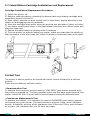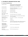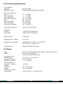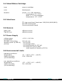
1
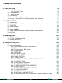
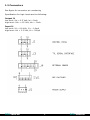
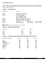
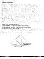
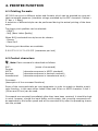
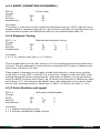
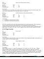
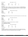
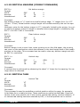
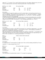
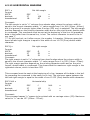
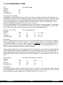
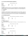
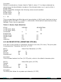
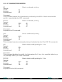
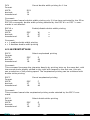
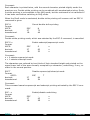
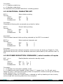
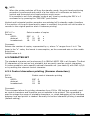
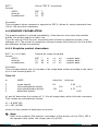
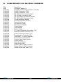
Technical
Manual
Mobile Printer 2000
DCA Intertel BV
Distributieweg 25, 2404 CM Alphen a/d Rijn
The Nederlands
Phone: +31(0)172 604963
Fax: +31(0)172 605237
website: www.dca-group.com
DCA Intertel
1
DCA Intertel
Table of Contens
1. DESCRIPTION
1.1 Printer Overview
1.1.1 Control Panel
1.1.2 Push Buttons
1.1.3 Signal Lights
1.2 Connectors
1.3 Sensor - Paper End
1.4 Sensor - Automatic Form/Paper loading and advance
4
4
5
5
5
7
8
9
2. INSTALLATION
2.1 Unpacking
2.2 Procedure for Installation
2.3 CAUTION!
2.4 Power Supply
2.5 Printer Set up
2.6 Paper Loading
2.7 Inked Ribbon Cartridge Installation and Replacement
2.8 Self Test
11
11
11
11
12
13
14
15
15
3.0 INTERFACES
3.1 TTL Interface
3.2 RS 232- Serial Interface
3.3 Parallel Interface
16
16
17
18
4. PRINTER FUNCTION
4.1 Printing Formats
4.2 Control characters
4.2.1 RESET (OPERATING COMMANDS.)
4.2.2 Aligment Tuning
4.2.3 Print direction and speed
4.2.4 Page Control
4.2.5 SENSORS
4.2.6 PRINTER STATUS
4.2.7 BUZZER CONTROL
4.2.8 DATA CONTROL
4.2.9 PAPER FEED
4.2.10 VERTICAL MARGINS (FORMAT COMMANDS)
4.2.11 VERTICAL TABS
4.2.12 HORIZONTAL MARGINS
4.2.13 HORIZONTAL TABS
4.2.14 TEXT JUSTIFICATION CONTROLS
4.2.15 PRINT QUALITY
4.2.16 PRINT PITCH (PRINTING STYLES)
4.2.17 CHARACTER WIDTH
4.2.18 PRINT STYLES
4.2.19 NATIONAL CHARACTER SET
4.2.20 POWER REDUCTION COMMANDS / select number of copies
19
19
19
20
20
20
21
22
22
23
24
25
27
27
29
30
31
31
32
33
34
36
36
DCA Intertel
2
DCA Intertel
4.3 CHARACTER SET
4.3.1 Control characters printing (German characters)
4.4 GRAPHIC CAPABILITIES
4.4.1 Graphics control characters
37
37
38
38
5. TECHNICAL INFORMATION MP 2000
5.1 Technical Specifications
5.2 Printing Specifications
5.3 Paper
5.4 Inked Ribbon Cartridge
5.5 Interfaces
5.6 Sensors
5.7 Power Supply
5.8 Environmental Limits
5.9 Dimensions and Weight
41
41
42
42
43
43
43
43
43
44
6. MAINTENANCE
6.1 Care and Cleaning
44
44
7. WARRANTY
44
8.
45
SPAREPARTS BY ARTICLE NUMBER
DCA Intertel
3
DCA Intertel
1. DESCRIPTION
1.1 Printer Overview
PRINTER HEAD
Power Board
Servermotor
Power Supply
Logic Board
Servermotor
HOT
Optional Board
TTL Serial Interface
Dip Switches
Control Panel
Product Outline
MP 2000 is an impact dot matrix printer with tractor and friction feed mechanism for
use in mobile environments.
The mechanism is equipped with a ballistic nine needle printing head, it is able to print
at 150 cps in draft mode and 25 cps in NLQ (Near Letter Quality) mode on multi-copy
paper (one original and up to four copies).
Due to its compact size and reduced weight (2.2 kg), the MP 2000 is particularly suited for portable applications.
Power requirements have been kept to a minimum by means of two DC motors with
integrated optical encoders. Using an integrated driver board, this ensures the same
precision positioning in comparison to stepping motors.
The MP 2000 can print in the graphics mode along with different character fonts, both
in draft and NLQ mode. It has also been developed mainly for portable applications,
e.g. when connected to a lap-top.
MP 2000 comes standard with 2 Kbytes input buffer and comes with the following
choices of interfaces:
-
TTL - level serial interface
RS-232 serial interface
Parallel interface
IRDA infra red
The interface flexibility ensures that the MP 2000 can work with almost any computer
system. The MP 2000 is software driven. It is compatible with the driver software of
EPSON LX 400 / LX800 and comes with his own windows ’95 and NT drivers.
DCA Intertel
4
DCA Intertel
1.1.1 Control Panel
The control panel is connected to the printer. It is fitted with four push buttons and
three LED’s.
1.1.2 Push Buttons
On line / Off line
This push button switches the printer on and off line. When the printer is “ON LINE”, it
is ready to accept data from the computer.
Likewise when it is switched “OFF LINE”, the carriage automatically moves to the center of the print span. When “ON LINE” the printer ignores the remaining push-buttons
(FF, LF, BF).
Form Feed
Paper advances by one sheet length (i.e. to the beginning of next page).
Line Feed
Paper advances by one line.
Back Feed
Paper retracts by one line.
When MP 2000 is “OFF LINE”, the combined activation of the “ON LINE” and “FORM
FEED” push-buttons causes the printer to go “ON LINE”. It assumes then the actual
paper position as “beginning of page”. Three beeps are generated to acknowledge the
operation.
1.1.3 Signal Lights
Power
This indicator lights when the printer is correctly powered. When power voltage is under 11.5 Vdc the “POWER” indicator flashes at 1 Hz rate. If the printer is battery operated, and the “POWER” indicator flashes at 1Hz rate, this means that the battery pack
is almost discharged, although the printer can still be operated for some time. Flashing
can be ignored or switched off (see 4.2.7).
DCA Intertel
5
DCA Intertel
On Line
This indicator turns on when the printer is ready to accept data. If the “ON LINE” led
flashes at 1 Hz rate, the printer switches automatically to “STAND-BY” mode (see
4.2.20).
Paper End
Comes on when the printer is out of paper.
ERROR indicator (special functions)
If the error indicator flashes and the “POWER ON” indicator flashes, this means that
the battery pack voltage has gone below the operating voltage. It is recommended to
turn the printer off in order to avoid the battery pack from getting damaged.
If the error indicator flashes and the “ON LINE” indicator flashes, this means that the
motor is locked due to some mechanical fault. It is recommended to turn the printer
off to avoid battery pack from over discharging.
After a “PAPER END” condition, when the printer is switched “ON LINE” after inserting
new paper, the actual paper position is assumed to be the “beginning of page”.
DCA Intertel
ONLINE
Paper End
ERROR
DCA Intertel
6
DCA Intertel
1.2 Connectors
See figure for connector pin numbering
Specification for logic levels are the following:
Output J1
low level: Vol < 0.5 Volt, lol = 5mA
high level: Voh > 4.5 Volt, loh = -5mA
Input J1
low level: Vil < 0.8 Volt, lil = -1.6mA
high level: Vol < 2.2 Volt, lih = 200μA
DCA Intertel
7
DCA Intertel
1.3 Sensor - Paper End
A reflective sensor is used on the MP 2000 to detect the “PAPER END” condition.
When this sensor detects the end of the currently printed sheet, the following takes
place:
a: printing stops
b: the printer switches to “OFF LINE” (ON LINE indicator goes off)
c: PE (Paper End) indicator comes on.
d: carriage moves to middle of the printing span.
In order to resume printing, a new sheet should be loaded and then press the “ON
LINE” button.
When the printer runs out of paper, this condition is signalled via the serial port by
automatically issuing a “status byte” every 100 ms; bit 2 of status will be at logic “1”
as follows:
paper present: bit 2 = PE = 0
out of paper: bit 2 = PE = 1
The “PAPER END” sensor is also used to detect an “open mechanism” condition; in
fact when the mechanism is open the sensor no longer detects the sheet and actions
described in a, b, c and d take place. The carriage moves to the center until a new
sheet is introduced. The printer mechanism is closed and the “ON LINE” push-button is
pressed.
The “PAPER END” sensor can be disabled using control sequence ESC 8; if disabled,
printing can take place even on the bottom edge of the sheet. The disabling sequence
must be done before any out-of-paper condition develops, should the input buffer
contain some unprinted characters, the disabling sequence would only add up in the
queue never to be executed.
The sensor status can be polled at every line by requesting the printer status; when
PE is active, approximately 10 character lines can be printed before the sheet terminates (with 1/6” line spacing).
Paper End Sensor
DCA Intertel
8
DCA Intertel
1.4 Sensor - Automatic Form/Paper loading and advance
The MP 2000 with serial interface has the ability to accept single forms.
By inserting a single form sheet (with a maximum of four copies) in the printer, the
paper will automatically go to “Top Of Form”. After the printing is finished, the paper/
form will automatically be ejected. To use this feature, the following software command settings have to be made.
MP 2000 TOF SETTING
-TOF driver with new board
-Possibility to read the TOF state by the host
-Automatic loading form/paper
-Form ejection over the feeding shaft
-Possibility to feed quickly forward/backward on “n” lines
OPERATIONS MADE ON DEFAULT
On default the printer ignores the PE detector. This allows the host to have the printer “ON-LINE” with or without paper. This condition is necessary to automatically load
form/paper.
The PE detector can be switched on when required.
COMMAND FOR AUTOMATIC FORM AND PAPER LOADING
ESC #l+b+d+n (“l” is an “L” in lowercase)
b = 0/1; Activates the beep signal when waiting for loading of paper.
d = Indicates the delay in increments of 5 msec. The PE detector is activated prior to
motor
starting for the form feed function.
n = When TOF sensor is activated, the form goes up by multiples of 1/216 inches to
TOF.
The printer waits for the paper to be loaded at the back of the unit, then the interlining motor will move until the TOF sensor is activated. From this position the paper
goes back n/216 inches, this new position is the Top Of Form.
The range of the parameter “n” is between 0 and 255 (approximately 0..30 mm).
This command must be sent before every automatic loading.
FORM EJECT COMMAND
ESC #e
The printer starts to eject the form until the PE detector is inactivated adding a “safety
time”. Before ejecting, the printer will print out the line buffer contents and disactivates the PE detector.
DCA Intertel
9
DCA Intertel
QUICK JUMP COMMAND
ESC #j+d+n
The printer makes a forward or backward feed of the paper of “n” lines.
d= 0 (binary or ASCII): forward feed
d= 1 (binary or ASCII): backward feed
n= number of lines (the dimension is set up by the proper command) to feed.
The paper feeding is limited according to the form dimensions. The dimension is set up
by the proper command (default 11 inches): it is not possible to go backward over the
top of the form or to go forward over the edge of the form.
Before the feeding of the paper, the printer will print out the contents of the line buffer.
READING OF TOF STATUS
It can be read on bit “b1” of the status byte: 1 = TOF sensor covered.
The TOF sensor is detected by regular periods.
During the form setting, the sampling is quicker than normal, in order to have more
precise precision. In all the other operating conditions, the TOF signal is tested every
100 msec.
DCA Intertel
10
DCA Intertel
2. INSTALLATION
2.1 Unpacking
Take the printer out of its shipping box and remove any padding material. It is advisable to keep the shipping box in case the printer needs to be re-shipped for repair,
replacement or placed into storage.
2.2 Procedure for Installation
Mechanical Installation
Paper movement should meet the following requirements:
−Paper should be guided to remain in a right angle position in line with the printer.
The printer does not feature any paper alignment device but only paper advancing/
retracting means. Therefore, any paper that is off-axis, misalignment cannot be corrected by the printer.
−Paper should remain parallel to the printing plane, also past the paper advancing
devices (sprocket tape/friction rollers) and particularly under the print head.
2.3 CAUTION!
• Do not print without inked ribbon or paper, this can lead to rapid print head
needle wear- out.
• When switching the printer on, it is advisable to check that the inked ribbon is
in place. (see Illustration: Cartridge installation.)
• Avoid putting foreign matters into the printer.
• Avoid moving the print head manually.
• Avoid mechanical shocks to the electronic boards and to the printing mechanism.
• Before starting to print, check that the inked ribbon cartridge is correctly installed,
the paper is loaded in the proper position and printer’s upper swivelling part is locked
to the lower one.
• If the printer has worked for some time, avoid touching the print head: it can be
overheated. It is advisable to wait a few minutes before attempting to replace the inked ribbon cartridge.
• Once the printer has been switched off, wait at least 10 seconds before switching it
on again, this enables the internal reset circuitry to work properly.
• Printer noise increases if the sheet is not in tight contact with the printing plane.
• Do not open the printer when it is operating.
• Switch the computer on before the printer and switch the printer off before the computer.
• This avoids dummy data being sent by the computer to the printer during the switching on/off sequence.
• Cleaning: do not use abrasive cleaners, unplug from mains before cleaning the printer.
DCA Intertel
11
DCA Intertel
2.4 Power Supply
The MP 2000 should be powered by a direct current source whose voltage falls strictly
within the following range : +10.8 to + 14.0 Vdc.
Owing to the print head’s needle firing, it is important to consider that the printer, acts
as a very discontinuous loads with I max. abs = 30A for 600 µs, and I max. typ = 20
A for 300 µs: peak repetition frequency is 900 Hz.
The power supply should therefore be able to deliver high peak currents without
overshooting the absolute Vmax. The ripple value should always remain within the
input voltage’s operating limits. The specification of the supply should be particularly
checked for the application whenever a switching power supply (SPS) is used, generally these exhibit a longer recovery time than their linear counterparts.
Any overvoltage or undervoltage, even for a short duration, can cause respectively
electronic circuit damage or microprocessor malfunction and should therefore be avoided. The same applies for electrostatic charges exceeding 5kV applied to the printer’s
frame.
The MP 2000 has been particularly developed for portable and battery operated systems; in the latter application, the following points should be noted:
• When the supply’s voltage is under the low threshold of 11.5V (batteries nearly drained) the “POWER ON” indicator flashes. This function can be disactivated by means of
the ESC #C n control (see 4.2.7.)
• When the voltage drops below 10.5 V (batteries drained) the printer stops working
while the Error indicator intermittently and the “POWER ON” indicator flashes. To reset
this error condition you need to switch the printer off, recharge the battery pack and
then switch the printer on again.
DCA Intertel
12
DCA Intertel
2.5 Printer Set up
The MP 2000 can operate with different hardware/software. It can be configurated by
using the SW1/SW2 DIP-switch set, as shown in Fig. 3 The function of the DIP-switches is shown in Table 3.
TABLE 3 - DIP SWITCHES
Dip Switch
Function
SW1-1
SW1-2
SW1-3
Baud rate (see table 4)
Baud rate (see table 4)
for serial interface:
ON = XON/XOFF mode
OFF= DTR/DSR mode
National character set (table
National character set (table
National character set (table
CRLF mode:
ON=
STAND-BY mode:
ON=
SW1-4
SW1-5
SW1-6
SW1-7
SW1-8
5)
5)
5)
enabled
enabled
OFF= disabled
OFF= disabled
NOTE: Factory standard setting: 4,5,6, ON
TABLE 4 - BAUD RATE SELECTION
Baud rate
SW1-1
SW1-2
1200
2400
4800
9600
ON
OFF
ON
OFF
ON
ON
OFF
OFF
TABLE 5 - NATIONAL CHARACTER SET SELECTION BY DIP SWITCH
National character set
USA
FRANCE
GERMANY
GREAT BRITAIN
DENMARK
SWEDEN
ITALY
SPAIN
DCA Intertel
SW1-6
SW1-5
ON
ON
ON
ON
OFF
OFF
OFF
OFF
ON
ON
OFF
OFF
ON
ON
OFF
OFF
13
SW1-4
ON
OFF
ON
OFF
ON
OFF
ON
OFF
DCA Intertel
Table 3 - Instructions
Using DIP switches SW1-4/5/6 a particular National Character Set can be selected;
this selection modifies the appearance of some characters according to table 10.
Software command “ESC R n” (see further) has priority over DIP-switch selection.
CRLF MODE = ON means that after every CR character (carriage return) sent by the
host, the printer automatically performs a LF (Line Feed) operation.
STAND BY MODE = ON: means that after a certain pre-set inactivity time (default
setting is 20 seconds) the printer switches to stand-by mode with 50% power drain
reduction.
Some of the settings selected using DIP-switches can be modified using software commands; if the DIP-switch settings are changed while the printer is on, the new configuration will be working after the printer is switched off and on.
2.6 Paper Loading
MP 2000 can print on DIN A4/A5 size single sheet paper/forms or multi part paper/
forms or continuous fan-fold paper with hole to hole spacing of 227 mm (8.94”).
See figure for correct paper loading.
The procedure for a correct paper loading is the following:
1) Set the printer “OFF LINE” pressing the relevant push-button
2) Open the printer by lifting lever A. (Fig. 1)
3) Insert single-sheet paper module by placing it over the printing plate, checking that
it is equally spaced with the printing area; in case of continuous fan-fold paper, be
sure that the sprockets do engage correctly in the holes provided near to the paper
edges.
4) Close the swivelling printer top and switch the printer “ON LINE”.
Paper feeding direction
DCA Intertel
14
DCA Intertel
2.7 Inked Ribbon Cartridge Installation and Replacement
Cartridge Installation/Replacement Procedure:
1) Switch the printer off.
2) Remove used cartridge by unlocking the bottom latch and rotating cartridge body
upwards as shown by arrow D.
3) Place ribbon extender on both studs B until it locks down, paying attention to the
ribbon not disengaging from the extender.
4) Move the cartridge body gently along the printing axis and place it down on holder
C; the ribbon should partly enter in the gap between the steel-wire ribbon holder and
the print head nose
5) Stretch the inked ribbon by turning knob A clockwise
6) Turn the printer on without loading any paper; make sure that after the switch-on
side movement of the print head, the ribbon is properly positioned under print head’s
nose.
2.8 Self Test
The printer is able to perform an internal self-check routine followed by a self test
printout.
There are two different self test modes:
- Demonstration Test
To execute this procedure, simply keep the “LINE FEED” push-button pressed while
the printer is powered up. The test procedure prints the first page where general information about MP 2000 is given and the second page showing the different fonts.
- Continuous Alphanumeric Test
To execute this selftest, it is necessary to keep the BACKFEED push-button pressed
while powering up the printer. The test produces a printout of the current software
version, followed by printing all the characters from 20hex and 7Fhex, each followed
by a space (40 characters per line, 66 lines per page).
DCA Intertel
15
DCA Intertel
3.0 INTERFACES
3.1 TTL Interface
Serial Data Format:
-1 start bit
-8 data bits
-No Parity
-1 stop bit
The transmission rate is selectable within the following values: 1200/2400/4800/9600
Baud.
Baud rate selection is performed by setting dip-switches SW1-1and SW1-2 according
to paragraph 2.5 Most important is to set SW1-3 according to the chosen serial
interface, this being the protocol XON-XOFF (XON = 17dec.= 11hex; XOFF = 19dec =
13hex) or the
DTR-DSR (hardware flag) mode. The TTL level control signals are as follows:
- TxD (output) Transmit Data.
The printer sends data to the computer over this line; when idle, this line is at logic
“1”.
- RxD (input) Receive Data.
The printer receives data transmitted from the computer over this line; idle at logic
“1”.
- DTR (output) Data Terminal Ready:
“0” = printer is ready to receive data
“1” = printer is busy and cannot receive data.
- DSR (input) Data Set Ready
Controls data exchange from printer to computer
“0” = printer can send data
“1” = printer cannot send data.
NOTE: the terms “input” and “output” refer to the printer.
DCA Intertel
16
DCA Intertel
Table 6 shows the pinout for connector J3 (10 way flat cable), used to connect the
printer to the host computer.
TABLE 6 - TTL SERIAL INTERFACE CONNECTOR J3
PIN
DIRECTION
FUNCTION
01
02
03
04
05
06
07
08
09
10
output
output
output
output
output
input
output
input
output
output
+Vp for
+Vp for
+5V for
+5V for
TXD
RXD
DTR
DSR
GND
GND
suppl.
suppl.
suppl.
suppl.
ext.
ext.
ext.
ext.
dev.
dev.
dev.
dev.
Imax=200mA
Imax=200mA
Imax=20mA
Imax=20mA
3.2 RS 232- Serial Interface
The printer’s serial TTL port is adapted to RS 232 C Standard interface. The pinout is
shown in Table 7.
TABLE 7 - RS-232C SERIAL INTERFACE CONNECTOR (DB 9)
Connection from Serial Cable Male to Female
01
---------------------
01
02
RX
---------------------
03
TX
03
04
05
06
07
08
09
TX
DTR
GND
DSR
RTS
CTS
RI
---------------------------------------------------------------------------------------------------------------------------------------------
02
06
05
04
08
07
09
RX
DSR
GND
DTR
CTS
RTS
RI
DCA Intertel
17
DCA Intertel
3.3 Parallel Interface
The parallel interface board allows for data exchange with the printer under the centronics parallel protocols. The pinout is shown in Table 8.
The parallel interface board can’t be used at the same time with the T.O.F. sensor.
TABLE 8 - PARALLEL INTERFACE CONNECTOR
PIN
SIGNAL
DESCRIPTION
01
02
03
04
05
06
07
08
09
10
11
12
13
14
/STROBE
D0
D1
D2
D3
D4
D5
D6
D7
/ACK
BUSY
PE
SLCT
/AUTO FEED
XT
/ERROR
/INIT
/SLCT-IN
..25 GND
STROBE for data read-in
DATA 0
DATA 1
DATA 2
DATA 3
DATA 4
DATA 5
DATA 6
DATA 7
new data request
data received
paper error/paper end
printer is ON
automatic LINE FEED
request
printer error
printer initialise
not connected
GROUND
15
16
17
18
DCA Intertel
18
DIRECTION
IN
IN
IN
IN
IN
IN
IN
IN
IN
OUT
OUT
OUT
OUT
IN
OUT
IN
(IN)
IN/OUT
DCA Intertel
4. PRINTER FUNCTION
4.1 Printing Formats
MP 2000 can print in different styles and formats, which can be selected by using suitable command sequence (character strings preceded by the ESC character: Escape =
27 dec = 1 Bhex)
A selection of different styles can be performed during the actual printing of the document.
Two basic print qualities can be selected:
- DRAFT
- NLQ (Near Letter Quality)
When NLQ is selected two styles can be chosen:
- Roman
- Sans Serif
Following print densities are available:
5 6 8.57 10 12 17.14 20 CPI (characters per inch)
4.2 Control characters
Note: Each command is described as follows:
ESC..
Format:
ASCII:
decimal:
hexadecimal:
(name of command)
(character sequence in ASCII standard)
(character sequence in decimal numbers)
(character sequence in hexadecimal num.)
Comment:
(description of the command functions)
Some of the commands take an input parameter in order to enable or disable a particular function; in this case either codes 00hex and 01hex or ASCII character 0 and 1
(30hex and 31hex) can be used.
Commands are executed immediately after they have been received; it should be kept
in mind, however, should the input buffer not be empty, the incoming commands will
be appended to the buffer queue and will be executed only after the preceding characters are printed.
DCA Intertel
19
DCA Intertel
4.2.1 RESET (OPERATING COMMANDS.)
ESC @
Format:
ASCII:
decimal:
hexadecimal:
Printer reset
ESC
27
1B
@
64
40
Comment:
The printer is reset to the initial conditions and default settings. ASCII code 64 can represent different characters according to the national character set used and the code
could therefore appear with different symbols on the keyboard(see table 10)
4.2.2 Aligment Tuning
ESC # J n
Format:
ASCII:
decimal:
hexadecimal:
Bidirectional alignment tuning
ESC
27
1B
#
35
23
J
74
4A
n
n
n
Comment:
0 ≤ n ≤ 20, default value 0hex ≤ n ≤ 14hex).
This command allows for the fine tuning of the print head alignment during bidirectional print. The fine alignment is required when extended ASCII graphic characters are
used (from 176 dec to 223 dec)
These graphic characters are normally printed bidirectionally, unless when unidirectional print is forced (ESC< and ESC U n commands). Graphics mode and NLQ mode
printing always take place unidirectionally. Alignment verification can be performed
using the BASIC program that follows; fig 15 shows how alignment is affected by different values of “n”. By changing the default value, fine alignment tuning can be obtained for both printing directions. Resolution is 1/480” (0.053mm) for each “n” unit.
4.2.3 Print direction and speed
ESC s n
Format:
ASCII:
decimal:
hexadecimal:
Half speed enable/disable
ESC
27
1B
s
115
73
n
n
n
Comment:
n = 1 enables half speed printing
n = 0 restores standard full speed printing
DCA Intertel
20
DCA Intertel
ESC <
Format:
ASCII:
decimal:
hexadecimal:
One line unidirectional printing
ESC
27
1B
<
60
3C
Comment:
The current line is forced to be printed with print head moving from left to right. This
command ceases after a CR (carriage return) is received.
ESC U n
Format:
ASCII:
decimal:
hexadecimal:
Unidirectional printing enable/disable
ESC
27
1B
U
85
55
n
n
n
Comment:
n = 1 enables unidirectional printing
n = 0 disables unidirectional printing
MP 2000 normally prints text with bidirectional print head movement. This command
forces unidirectional print and allows for a more accurate text positioning.
Unidirectional printing can be useful when the ASCII extended graphic character set is
used (from 176 dec to 223 dec.), which requires the finest vertical alignment tuning.
4.2.4 Page Control
FF
Format:
ASCII:
decimal:
hexadecimal:
Form Feed
FF
12
0C
Comment:
This comment forces all data in the input buffer to be printed and paper advanced by a
length equal to the set page length.
ESC C n
Format:
ASCII:
decimal:
hexadecimal:
Page length in lines
ESC
27
1B
C
67
43
n
n
n
Comment:
Page length is set to “n” lines. The range for “n” is from 1 to 127 (01 hex....7Fhex)
Physical page length is determined by the actual line spacing; maximum physical
length is 12” and if a line spacing of 1/6” is chosen, the maximum value for “n” will be
72. The beginning of the page is assumed to be the current page position. Any bottom
margin setting established by an ESC N n command is cleared whenever page length
setting is changed. Default page length is set to 66 lines.
DCA Intertel
21
DCA Intertel
ESC C NUL n
Format:
ASCII:
decimal:
hexadecimal:
Page length in inches
ESC
27
1B
C
67
43
NUL
0
00
n
n
n
Comment:
Page length is set to “n” inches ( 1 inch = 25.2 mm), where “n” is ranged between 1
to 12 (01hex...0Chex). The beginning of the page is assumed to be the current page
position. Any bottom margin setting established by an ESC N n command is cleared.
4.2.5 SENSORS
ESC 8
Format:
ASCII:
decimal:
hexadecimal:
Disable Paper End Sensor
ESC
27
1B
8
56
38
Comment:
Paper End is disabled so that printing can be performed right down to the bottom edge
of the sheet.
ESC 9
Format:
ASCII:
decimal:
hexadecimal
Enable Paper End Sensor
ESC
27
1B
9
57
39
Comment:
Cancels the ESC 8 command. Paper End sensor is enabled.
4.2.6 PRINTER STATUS
ESC # S
Format:
ASCII:
decimal:
hexadecimal:
Printer status request
ESC
27
1B
#
35
23
S
83
53
Comment:
The printer responds to this command by sending to the host a status byte, where
information about activity, batteries and paper are given as specified in the following
table (obviously, the printer can respond only when it is ON LINE).
DCA Intertel
22
DCA Intertel
b7
b6
1
R
b5
R
b4
A
b3
B
b2
PE
C
b1
b0
R
where:
R
means reserved: these bits are not meant to be handled by
the user. Therefore these should not be used.
A
means printer activity:
A=1 printer is ON LINE and is actually printing
A=0 printer is ON LINE and is waiting for data to be
printed.
B
means battery status:
B=0 batteries are charged
(supply voltage is over the 11.5 Vdc threshold)
B=1 batteries are low
(supply voltage is under the 11.5 Vdc threshold)
PE
means paper sensor status:
PE=0 paper present
PE=1 out of paper
C
means T.O.F. sensor status:
C=1 paper present
C=0 no paper
NOTE:If the printer detects an out-of-paper condition, and the paper end sensor
has not been disabled by the ESC 8 command, the status byte is automatically
sent back to the host (one transmission every 100 ms).
In this condition, although the printer is OFF LINE (see paragraph 1.3.2) the
status byte may have bit A=1 (printer activity) if there are characters left in the
input buffer still to be printed.
4.2.7 BUZZER CONTROL
BEL
Format:
ASCII:
decimal:
hexadecimal:
Sound the buzzer
BEL
7
07
Comment:
This character makes the control panel buzzer emit a short beep.
ESC # C n
Format:
ASCII:
decimal:
Hexadecimal:
DCA Intertel
Enable/disable LED flashing
ESC #
27
35
1B
23
C
67
43
23
n
n
n
DCA Intertel
Comment:
n = 1 enables “POWER ON” LED flashing
n = 0 disables “POWER ON”LED flashing
This command allows for disabling the POWER ON Led flashing, that normally comes
on when supply voltage goes under the 11.5 Vdc threshold. Disabling this function
could be necessary when the printer is powered at a voltage value between 10.8 and
11.5 Vdc.
4.2.8 DATA CONTROL
CR
Format:
ASCII:
decimal:
hexadecimal:
Carriage Return
CR
13
OD
Comment:
All data in the buffer is printed and the carriage moves to the beginning of the line. If
DIP-switch SW1-7 is ON, a Line Feed is automatically issued.
CAN
Format:
ASCII:
decimal:
hexadecimal:
Cancel Line
CAN
24
18
Comment:
Cancels all printable characters in the line preceding the command. It cannot cancel
the control characters issued in the current line.
BS
Format:
ASCII:
decimal:
hexadecimal:
(Backspace)
BS
8
08
Comment:
All data stored in the input buffer are printed, then the print head is moved back by
one print position for each BS character received, thus, allowing for character to over
print. The command is ignored; if the printer is at the very beginning of a line or if the
preceding character is HT (Horizontal Tab). The BS command should not be used when
the center justified printing mode is selected (ESC a 1 command).
DCA Intertel
24
DCA Intertel
4.2.9 PAPER FEED
LF
Format:
ASCII:
decimal:
hexadecimal:
Line Feed
LF
10
OA
Comment:
All data in the input buffer are printed and the sheet advances by one line. The length
of the actual fed paper is equal to the set line spacing.
ESC J n
Format:
ASCII:
decimal:
hexadecimal:
Advance sheet by n/216 inch
27
1B
ESC
74
4A
J
n
n
n
Comment:
Paper advances by n/216 of an inch (1/216” = 0.118mm).
The range for “n” should be from 0 to 255 (OOhex...FFhex).
This command does not move the carriage to the beginning of the next line nor does
it affect subsequent lines: it can be seen as a means to obtain an immediate fractional
line feed with no carriage return for specific paper positioning purposes. If a permanent fractional line spacing is required, command ESC 3 n should be used (see further
on).
ESC 0
Format:
ASCII:
decimal:
hexadecimal:
Set line spacing to 1/8 inch
ESC
27
1B
0
48
30
Comment:
Line spacing is set to 1/8 of an inch (3.175 mm) for subsequent line feed commands.
It should be noted that value “zero” in the command sequence is the ASCII code zero.
(code 48 dec.)
ESC 1
Format:
ASCII:
decimal:
hexadecimal:
Set line spacing to 7/72 inch
ESC
27
1B
1
49
31
Comment:
Line spacing is set to 7/72 of an inch (2.47 mm) for subsequent line feed commands.
DCA Intertel
25
DCA Intertel
ESC 2
Format:
ASCII:
decimal:
hexadecimal:
Set line spacing to 1/6 inch
27
1B
ESC
50
32
2
Comment:
Line spacing is set to 1/6 of an inch (4.23 mm) for subsequent line feed commands.
ESC 3 n
Format:
ASCII:
decimal:
hexadecimal:
Set line spacing to n/216 inch
ESC
27
1B
3
51
33
n
n
n
Comment:
Line spacing is set to n/216 of an inch (1/216” = 0.118 mm) for subsequent line feed
commands. The range for “n” is from 0 to 255 (OOhex...FFhex).
ESC A n
Format:
ASCII:
decimal:
hexadecimal:
Set line spacing to n/72 inch
ESC
27
1B
A
65
41
n
n
n
Comment:
Line spacing is set to n/72 of an inch (1/72” = 0.353 mm) for subsequent line feed
commands. The range for “n” is from 0 to 85 (00hex...55hex).
Note: When using uni A4 sheets on MP 2000 printer the minimum line spacing
pitch becomes 1/217 of an inch (0.117 mm).
This modification affects the ESC J n and ESC 3 n commands which therefore respect the 1/217 inch pitch; the correct values for remaining line feed commands
are 3.16 mm (ESC 0),
2.46 mm (ESC 1), 4.21 mm (ESC 2) and 0.351 mm (ESC A n).
DCA Intertel
26
DCA Intertel
4.2.10 VERTICAL MARGINS (FORMAT COMMANDS)
ESC N n
Format:
ASCII:
decimal:
hexadecimal:
Set bottom margin
ESC
27
1B
N
78
4E
n
n
n
Comment:
Set bottom margin to “n” lines from sheet’s bottom edge; “n” ranges from 1 to 127
(01hex...7Fhex). Actual bottom margin length will be determined by the set line spacing.
Maximum value for the bottom margin is 12”, internally limited by the printer. Any prior setting of bottom margin’s length is cancelled when page length is modified by the
ESC C n or ESC C NUL n commands.
ESC 0
Format:
ASCII:
decimal:
hexadecimal:
Clear bottom margin
ESC
27
1B
0
79
4F
Comment:
Bottom margin is set to zero lines, when printing out on fan-fold paper, the printing
can occur on the perforation unless the software in the host keeps track of the head’s
position on the page. This command can be used to clear any bottom margin set with
an ESC N n command
ESC f 1 n
Format:
ASCII:
decimal:
hexadecimal:
Vertical skip
ESC
27
1B
f
102
66
SOH
1
01
n
n
n
Comment:
A vertical skip is performed by advancing the sheet “n” times the line spacing. No carriage return is executed.
4.2.11 VERTICAL TABS
VT
Format:
ASCII:
decimal:
hexadecimal:
Vertical Tab
VT
11
0B
Comment:
This command is used to predefine a vertical position within the page, for example,
to facilitate form or table printing. These positions are called vertical tabs. Paper advances to the next position set in the current vertical tab setting (vertical channel). If
no vertical tab setting has been selected by ESC / c the tab position set in vertical
DCA Intertel
27
DCA Intertel
channel “n” 0 is used. If no vertical tab has been set, the paper advances by one line.
This command prints out all the remaining data left in the input buffer.
ESC B n1 n2...NUL
Format:
ASCII:
decimal:
hexadecimal:
Set vertical tabs
ESC
27
1B
B
66
42
n1
n1
n1
n2...NUL
n2...0
n2...00
Comment:
This command is used for setting up to 16 vertical tabs, to be performed at the current line spacing. Tab positions are entered as n1, n2...and so on (where “n” ranges
from 1 to 255 dec) and are in increasing order (i.e. n1<n2<n3). The NUL character
indicates the end of the command.
If the line spacing is modified after giving this command, tab positions are not affected. This command sets tabs for vertical setting no. 0 (channel 0). Tabs can be cancelled by the ESC B NUL command (i.e. by omitting parameters n1, n2 etc.)
ESC b c n1 n2...NUL
Format:
ASCII:
decimal:
hexadecimal:
Set vertical tabs channels
ESC
11
1B
b
98
62
c
c
c
n1
n1
n1
n2...NUL
n2...0
n2...00
Comment:
This command is similar to the ESC B command, by introducing parameter c, to select
a particular vertical tabs setting; c will be within 0 and 7, thus making it possible to
select up to 8 different vertical tab channels.
After the selection of vertical tabs channels are made by using ESC / c command. Character NUL indicates the end of the command; tabs settings can be cancelled by the
ESC b NUL command (i.e. omitting parameters c n1 n2 etc.)
ESC / c
Format:
ASCII:
decimal:
hexadecimal:
Select vertical tabs channels
ESC
27
1B
/
47
2F
c
c
c
Comment:
All subsequent VT commands will make use of the vertical setting selected by the parameter c. c value ranges from 0 to 7.
ESC e 1 n
Format:
ASCII:
decimal:
hexadecimal:
Set vertical tabs increments
ESC
27
1B
e
101
65
SOH
1
01
n
n
n
Comments:
The increment of vertical tabs is set to “n” current line spacings.
DCA Intertel
28
DCA Intertel
4.2.12 HORIZONTAL MARGINS
ESC 1 n
Format:
ASCII:
decimal:
hexadecimal:
Set left margin
ESC
27
1B
l
108
6C
n
n
n
Comment:
The left margin is set to “n” columns from sheets edge, where the column width is
equal to the current character width; “n” value ranges from 0 to 160 (00hex...A0hex),
but it is ignored if a margin higher than 8 inches (230 mm) is selected. The left margin
position depends on the printing character width and on the print format, double width
or condensed. This command must be sent at the beginning of the line: all preceding
data in the buffer from the same line, is lost. The correct character to send is the lower case “l”
(“l” for left) and not, as it often occurs, the number 1 character. Minimum space between left and right margins is equal to the width of one 10 CPI (Pica) double width
character.
ESC Q n
Set right margin
Format:
ASCII:
ESC
Q
n
decimal:
27
81
n
hexadecimal:
1B
51
n
Comment:
The right margin is set to “n” columns from sheet’s edge where the column width is
equal to the current character width. “n” value ranges from 1 to 255 (01hex...FFhex).
The right margin position depends on the printing character width and on the print
format, double width or condensed. This means that the maximum right margin is the
rightmost column, which is less than 255.
This command must be sent at the beginning of a line, because all the data in the buffer preceding the command in the same line is lost, The minimum space between the
left and right margin is equal to the width of one 10 CPI (Pica) double width character.
ESC f NUL n
Format:
ASCII:
decimal:
hexadecimal:
Horizontal skip
ESC
27
1B
f
102
66
NUL
0
00
n
n
n
Comment:
This command causes “n” spaces to be printed with no carriage return (CR). Maximum
value for “n” can be 127 (01hex...7Fhex).
DCA Intertel
29
DCA Intertel
4.2.13 HORIZONTAL TABS
HT
Format:
ASCII:
decimal:
hexadecimal:
Horizontal tabs
HT
9
09
Comment: Pre-setting
Presetting of horizontal positions within the line is possible with the HT character, to
facilitate for example form or table printing. By this command the print head is moved
to the next position of horizontal tab setting. Horizontal tabs are initially set at intervals of 8 characters in the default PICA (10 CPI) format, which corresponds to one
horizontal tab set every 8/10 of an inch (20.3 mm).
Further modifications of the character pitch do not affect horizontal tabs. For example,
if we shift from Pica (10 CPI) to Elite (12 CPI) characters, the first tab will still be at
8/10 of an inch from the left margin and so on for subsequent tabs.
ESC D n1 n2...NUL
Format:
ASCII:
decimal:
hexadecimal:
Set horizontal tabs
ESC
27
1B
D
68
44
n1
n1
n1
n2...NUL
n2...0
n2...00
Comment:
This command allows for setting up to 32 horizontal tab positions. Tabs are represented by parameters n1, n2 etc., where “n” value ranges from 1 to 159 (01hex...9Fhex)
in increasing order (n1<n2<n3 etc.). Maximum practical value for horizontal tab is
equal to the maximum number of characters per line less 1 unit (see para. 5.2) The
NUL character indicates the end of the command.
Tab positions depend on the character pitch set when this command is issued and will
not be affected by a further modification of the character pitch. The command ESC D
NUL (without parameters) clears all horizontal tabs. When the printer is turned on or
initialised, tabs are set at intervals of 8 Pica characters, i.e. at intervals of 8/10 of an
inch.
ESC e NUL n
Format:
ASCII:
decimal:
hexadecimal:
Set horizontal tabs increments
ESC
27
1B
e
101
65
NUL
0
00
n
n
n
Comment:
Horizontal tabs are set at regular intervals of “n” spaces. The maximum value that can
be set depends on the current character width and is 21, 25 and 36 at 10 CPI, 12 CPI
and condensed mode respectively. Default value at 10 CPI is n = 8.
DCA Intertel
30
DCA Intertel
4.2.14 TEXT JUSTIFICATION CONTROLS
ESC a n
Format:
ASCII:
decimal:
hexadecimal:
Select justification mode
ESC
27
1B
a
97
61
n
n
n
Comment:
It is often convenient to print one or more centered lines, or texts with right and/or
justified margins. This command causes text justification to be automatically performed while printing. The type of justification set depends on the value assigned to n:
n = 0 left (default)
n = 1 centered
n = 2 right
Justification is performed when the printer receives a CR, LF or FF code, or when the
input buffer is full. The ESC a n command should always be given at the beginning of
a new line, as all data preceding it on the same line is lost. If bit image graphics elements and text elements are mixed in the line, justification is not performed properly.
4.2.15 PRINT QUALITY
ESC x n
Format:
ASCII:
decimal:
hexadecimal:
Select NLQ (Near Letter Quality) or draft mode
ESC
27
1B
x
120
78
n
n
n
Comment:
n = 0 selects draft mode
n = 1 selects NLQ mode
By selecting the NLQ mode the default font (Roman), or the last selected font, if any,
is set.
ESC k n
Format:
ASCII:
decimal:
hexadecimal:
Select character font in NLQ
ESC
27
1B
k
107
6B
n
n
n
Comment:
Selects one of the two fonts available in NLQ
n = 0 Roman
n = 1 Sans Serif
ESC ! n
Format:
ASCII:
decimal:
hexadecimal:
DCA Intertel
Select master style
ESC
27
1B
!
33
21
n
n
n
31
DCA Intertel
Comment:
Selects a combination of styles listed in Table 9, where “n” is a figure obtained by
summing up the identification numbers of the desired styles, e.g. to print a title in
double width,
double strike Elite character the following values must be added:
Elite (12CPI)
1
double-strike
16
double-width
32
--n = 49
This command does not affect the print type selection in NLQ mode, that has to be separately set by the ESC x n or ESC k n commands. Subscript and superscript printing
settings, if any, are not cancelled.
Table 9 - Master Style Selection:
STYLE
10 CPI pitch (Pica)
12 CPI pitch (Elite)
Condensed
Emphasized
Double-strike
Double-width
Italic
Underline
DECIMAL
0
1
4
8
16
32
64
128
HEXADECIMAL
00
01
04
08
10
20
40
80
4.2.16 PRINT PITCH (PRINTING STYLES)
print pitch is the number of characters printed in one inch (25.4 mm). The print pitch
is expressed as “Characters Per Inch” or “CPI”.
ESC P
Format:
ASCII:
decimal:
hexadecimal:
Select Pica Characters (10 CPI)
ESC
27
1B
P
80
50
Comment:
This command selects the Pica (10 CPI) pitch, which is the default character pitch.
ESC M
Format:
ASCII:
decimal:
hexadecimal:
Select Elite pitch (12 CPI)
ESC
27
1B
M
77
4D
Comment:
The Elite pitch allows for a greater print density (12 CPI)
DCA Intertel
32
DCA Intertel
4.2.17 CHARACTER WIDTH
SI
Format:
ASCII:
decimal:
hexadecimal:
Select condensed printing
SI
15
0F
Comment:
This command causes the characters be reduced by the 60% of their normal width
and it is cancelled by the DC2 command.
ESC SI
Format:
ASCII:
decimal:
hexadecimal:
Select condensed printing
ESC
27
1B
SI
15
0F
Comment:
Equivalent to SI command.
DC2
Format:
ASCII:
decimal:
hexadecimal:
Comment:
This command cancels
SO
Format:
ASCII:
decimal:
hexadecimal:
Cancel condensed printing
DC2
18
12
condensed printing if activated by the SI or ESC SI commands.
Select double width printing for 1 line
SO
14
0E
Comment:
This command doubles the width of all characters for 1 line; it is cancelled either by a
CR (carriage return) or a DC4 command.
ESC SO
Format:
ASCII:
decimal:
hexadecimal:
Select double width printing for 1 line
ESC
27
1B
SO
14
0E
Comment:
Equivalent to the SO command.
DCA Intertel
33
DCA Intertel
DC4
Format:
ASCII:
decimal:
hexadecimal:
Cancel double width printing for 1 line
DC4
20
14
Comment:
This command cancels double width printing only if it has been activated by the SO or
ESC SO commands; double width printing selected by the ESC W n or ESC ! n commands is not affected.
ESC W n
Format:
ASCII:
decimal:
hexadecimal:
Enable/disable double width printing
ESC
27
1B
W
87
57
n
n
n
Comment:
n = 1 enables double width printing
n = 0 disables double width printing
4.2.18 PRINT STYLES
ESC E
Format:
ASCII:
decimal:
hexadecimal:
Select emphasized printing
ESC
27
1B
E
69
45
Comment:
This command increases the character density by printing twice on the same dot, with
the second stroke slightly shifted to the right with respect to the first one, this causes a reduction of the printing speed. The emphasized printing can be combined with
double strike printing.
ESC F
Format:
ASCII:
decimal:
hexadecimal:
Cancel emphasized printing
ESC
27
1B
F
70
46
Comment:
This command cancels the emphasized printing mode selected by the ESC E command.
ESC G
Format:
ASCII:
decimal:
hexadecimal:
DCA Intertel
Select double strike printing
ESC
27
1B
G
71
47
34
DCA Intertel
Comment:
Each character is printed twice, with the second character printed slightly under the
previous one. Double strike printing can be combined with emphasized printing. Double strike printing is not available in the NLQ mode, but the command is not cancelled if
it has been sent before switching to NLQ mode.
When the Draft mode is reselected, double strike printing will resume until an ESC H
command is given.
ESC H
Format:
ASCII:
decimal:
hexadecimal:
Cancel double strike printing
ESC
27
1B
H
72
48
Comment:
Double strike printing mode, which was selected by the ESC G command, is cancelled.
ESC S n
Format:
ASCII:
decimal:
hexadecimal:
Enable subscript/superscript mode
ESC
27
1B
S
83
53
n
n
n
Comment:
n = 0 selects superscript mode
n = 1 selects subscript mode
The characters are reduced by two thirds of their standard height and printed on the
upper/lower half of the area normally occupied by a character; underlining, if any, remains in the normal position.
ESC T
Format:
ASCII:
decimal:
hexadecimal:
Disable superscript/subscript mode
27
1B
ESC
84
54
T
Comment:
This command cancels superscript and subscript printing activated by the ESC S command.
ESC - n
Format:
ASCII:
decimal:
hexadecimal:
DCA Intertel
Enable/disable underlining
ESC
27
1B
45
2D
n
n
n
35
DCA Intertel
Comment:
n = 1 enables underlining
n = 0 disables underlining
All characters are printed underlined, including spaces.
4.2.19 NATIONAL CHARACTER SET
ESC 4
Format:
ASCII:
decimal:
hexadecimal:
Select italics printing
ESC
27
1B
4
52
34
Comment:
Characters following this command are printed in italics.
ESC 5
Format:
ASCII:
decimal:
hexadecimal:
Cancel italics printing
ESC
27
1B
5
53
35
Comment:
This command cancels italics printing selected by the ESC 4 command.
ESC R n
Format:
ASCII:
decimal:
hexadecimal:
Select national character set
ESC
27
1B
R
82
52
n
n
n
Comment:
Parameter selects the national character set to be used, as shown in Chapter 8. This
command has priority over the hardware selection performed by DIP-switches SW1-4/
5/6.
4.2.20 POWER REDUCTION COMMANDS / select number of copies
ESC # s n
Format:
ASCII:
decimal:
hexadecimal:
Enable/disable automatic standby mode
ESC #
27
35
1B
23
s
115
73
n
n
n
Comment:
n = 0 disables the automatic standby mode.
n > 0 enables automatic standby mode, where “n” ranges from 1 to 25 and represents the time in seconds where the printer is inoperative before entering the standby
mode (default time = 20 seconds).
In the standby mode the current drain is reduced by half by disabling all the circuitry
not involved with receiving data from the computer.
DCA Intertel
36
DCA Intertel
NOTE:
When the printer switches off from the standby mode, the print head positioning
procedure is performed and a shift of a few tenths of a millimetre on both the
vertical and horizontal print head positions might occur.
It is possible to exit from standby mode at any time by sending the ESC # s 0
command or by pressing the “ON LINE” push button.
Vertical and horizontal position encoders are switched off in standby mode, therefore
if the position of the print head and/or paper is modified, the printer will not be able to
recover to the original position when it resumes printing.
ESC # P n
Format:
ASCII:
decimal:
hexadecimal:
Select number of copies
ESC #
27
35
1B
23
P
80
50
n
n
n
Comment:
Selects the number of copies, represented by n, where “n” ranges from 1 to 4. The
lower is the “n” value, the lowest is consumption, as the command acts on the needle
firing time.
Default value is 4.
4.3 CHARACTER SET
The standard character set (enclosures A) is IBM full ASCII 256 in all formats. The first
32 characters of the set are not printable, but are partly used as control characters.
It is also possible to set a specific national character set (see table 9) with SW1-4/5/6
or by sending the relevant control character.
4.3.1 Control characters printing (German characters)
ESC 6
Format:
ASCII:
decimal:
hexadecimal:
Enable control character printing
ESC 6
27
54
1B
36
Comment:
This command allows for printing characters from 128 to 159 that are normally used
as control characters and therefore are not suitable to be printed. This command is
used to enlarge the range of printable characters, or, when debugging of the interface
between host and printer is needed. Normally the control character printing is enabled
(default setting).
DCA Intertel
37
DCA Intertel
ESC 7
Format:
ASCII:
decimal:
hexadecimal:
Cancel “ESC 6” commands
ESC 7
27
55
1B
37
Comment:
This command, whose response is opposite to ESC 6, allows for using characters from
128 to 159 as control characters.
4.4 GRAPHIC CAPABILITIES
The graphics pattern is printed immediately; if the dots are more than the possible
dotline, the printer begins an other line.
If you do not put CR at the end, everything that follows the graphics printed, is set
sideways of it. The arrival of a graphics command causes the printing of the line buffer
and sideways follows the graphics.
4.4.1 Graphics control characters
ESC * m n1 n2 data
format:
ASCII:
decimal:
hexadecimal:
General bit image command
ESC *
27
42
1B
2A
m
m
m
n1
n1
n1
n2
n2
n2
… graphic data …
… graphic data …
… graphic data …
Comment:
This command selects one of a number of bit image data modes according to the value
of m in the following table 10.
Table 10
m
MODE
dots/inch
0
1
2
3
single density
low speed/double density
high speed/double density
quadruple density
60
120
120
240
dots/mm
2.36
4.72
4.72
9.45
n1 and n2 determine the number of “n” of a bit image data, which follw the command.
Their values are calculated as follows:
n1 = d MOD 256
n2 = INT (d/256)
where d is the number of data bytes to be sent.
Note:
MOD is the modulus 256 operator (remainder of the division of d by 256); INT is
the operator that yields the integer part of (d/256).
DCA Intertel
38
DCA Intertel
ESC K n1 n2 d
format:
ASCII:
decimal:
hexadecimal:
select 8-bit single density bit image printing
ESC
27
1B
K
75
4B
n1
n1
n1
n2
n2
n2
d
d
d
Comment: Single density bit image mode is selected.
If d value represents the total number of columns:
n1 = dMOD 256
n2 = INT (d/256)
This has the same effect as “ESC” with m set to 0. It is also possible to define again
“ESC K+ to select another mode using “ESC?”.
ESC L n1 n2 d
select 8-bit double density bit image printing
format:
ASCII:
ESC
L
n1
n2
d
decimal:
27
76
n1
n2
d
hexadecimal:
1B
4C
n1
n2
d
Comment: low speed double-density, bit image graphics mode is selected.
If d value represents the total number of colums:
n1 = dMOD 256
n2 = INT (d/256)
This has the same effect as “ESC” with m set to 1. It is also possible to define again
“ESC K” to select another mode using
“ESC?”.
ESC Y n1 n2 d
format:
ASCII:
decimal:
hexadecimal:
select 8-bit double speed double density bit image printing
ESC
27
1B
Y
89
58
n1
n1
n1
n2
n2
n2
d
d
d
Comment: double speed, double density bit image graphics mode is selected.
If d value represents the total number of columns:
n1 = dMOD 256
n2 = INT (d/256)
This has the same effect as “ESC” with m set to 2. It is also possible to define again
“ESC K” to select another mode using “ESC?”.
DCA Intertel
39
DCA Intertel
ESC Z n1 n2 d
format:
ASCII:
decimal:
hexadecimal:
select 8-bit quadruple-density image printing
ESC
27
1B
Z
90
5A
n1
n1
n1
n2
n2
n2
d
d
d
Comment: quadruple-density, bit image graphics is selected.
If d value represents the total number of columns:
n1 = dMOD 256
n2 = INT (d/256)
This has the same effect as “ESC” with m set to 3. It is also possible to define again
“ESC K” to select another mode using “ESC?”.
ESC ? n m
format:
ASCII:
decimal:
hexadecimal:
keyboard:
re-assign bit image commands
ESC
27
1B
CTRL[
?
63
3F
?
n
m
n
m
n
m
see below
Comment: One of the general bit image modes listed under “ESC * m n1 n2 data” is
assigned to any of the commands “ESC K”, “ESC L”, and “ESC Z”.
The value of m corresponds to the mode m in “ESC * n1 n2 data”.
If control characters are being used this would be input by pressing CTRL and a key in
the range @ to G.
n is the ASCII code for the command which is to be changed:
K, L, Y or Z; thus it is the character K, L, Y or Z which is sent.
DCA Intertel
40
DCA Intertel
5. TECHNICAL INFORMATION MP 2000
5.1 Technical Specifications
-printing housing
Caged enclosure(for EMI suppression)
3 parts made of 1 mm Stainless Steel
Dampingpads for noise suppression
-printing method
dot matrix impact printing (ballistic, 9 pins)
-printing direction
horizontal, bi-directional
printing with optimum path, logic search
-paper movement
forward/backward
-paper transport
friction and tractor
-printing speed
150 char/s in draft mode
-paper advance speed
-draft mode:
150 ms/line typical (1/6” line spacing)
-NLQ and graphics mode
-Continuous line
feeding ex formfeed
200 ms/line typical with intermittent paper advance
(1/16” line spacing)
100 ms/line = 0.6 s/inch = 4.35 cm/s typical
-buffer capacity
2 KBytes
-MCBF
1.2x10⁶ lines
-expected head life
300x106 strokes/needle, equal to 190x106 characters
(given an average density of 14 dots/character).
-vibration test:
3 axis sinusoidal
vibration test at
resonance frequency
3-200 Hz random vibration (MIL-STD810D/514.3)
-shock test
(non-operational mode)
DCA Intertel
0.5 G for 15 min. along each axis
1 G for 30 min. along each axis
50 G for 8ms along each axis
41
DCA Intertel
5.2 Printing Specifications
-print quality:
graphics
alphanumerical
-characters per line:
pica
pica expanded
pica condensed
pica cons. and exp.
elite
elite expanded
elite condensed
elite cons. and exp.
full bit image
Draft/Roman NLQ/Sans Serif NLQ
80
36
68
96
48
160
80
(10 CPI)
(5 CPI)
(17 CPI)
(8.5 CPI)
(12 CPI)
(6 CPI)
(20 CPI)
(10 CPI)
-actual printing area
203.2 mm (8 Inches)
-resolution:
vertical
horizontal
216 DPI (8.50 dot/mm)
240 DPI (9.45 dot/mm)
-dots per line
1920 max
-standard char. height
2.47 mm
-standard line spacing
variable within 1/216” and 255/216”
(0.118 mm ...29.99 mm)
-character set
IBM FULL ASCII 256 (fig.)
5.3 Paper
-Type
-width
-sprocket hole to
hole distance
-sprocket hole pitc
-number of copies
-max thickness
(original + copies)
-weight
1 original
copies
maximum module
composition
DCA Intertel
MP 2000: DIN A4/A5 single sheet or continious forms
210 mm (DIN A4/A5)
240 mm (continious forms)
227 mm +/- 0.125 mm
12.7 mm(0.5”)
3 + 1 original
0.25 mm
55 + 90 gr/m2
45 + 55 gr/m2
(3x55 gr/m2) + (1x80 gr/m2)
42
DCA Intertel
5.4 Inked Ribbon Cartridge
-type
snap-on cartridge
-color
black/purple
-duration
purple: 1.2 x 10⁶ characters
temperature: 5° + 50°C
black: 0.7 x 10⁶ characters
temperature: 10° + 50°C
5.5 Interfaces
TTL logic serial level (baud rate 1200/2400/4800/9600)
RS-232C serial board
Centronics parallel board
5.6 Sensors
-paper end
-Top Of Form
reflective sensor
reflective sensor
5.7 Power Supply
-voltage range
-current drain
ON LINE, not printing
standby (selec. by SW1-8)
printing
+10.8 + 14.0 Vdc
160 mA max
80 mA max
2 A average value
20 A peak typical (for 600 µs)
30 A peak (for 300 µs max)
peak repetition frequency 900 Hz
5.8 Environmental Limits
-operating conditions
temperature
relative humidity
(not condensing)
-5°...+40°C (+23°...+104°F)
15%...85% RH
-non operating conditions
temperature
relative humidity
(not condensing)
-15°...+70°C (+5°...+158°F)
5%...85% RH
DCA Intertel
43
DCA Intertel
5.9 Dimensions and Weight
-dimensions
length
height
width
351 mm
82 mm
83 mm
-weight
2.2 kg
6. MAINTENANCE
6.1 Care and Cleaning
The MP 2000 does not require special maintenance, except for the following:
−Periodical cleaning, to the print head bearing rod with isopropylic alcohol or something similar.
−When the printer has suffered a major shock or whenever bad quality printing is
experienced, you need to measure the distance between print head and printing plate.
The distance, measured with a thickness gauge with the printer closed and no inked
ribbon interposed, should be 0.55 mm +/- 0.05 mm.
−The printers mechanism requires regular cleaning to remove any foreign matters
such as dust, paper chips etc., which can cause mechanism malfunctions.
7. WARRANTY
−The MP 2000 printer is subject to a strict factory quality control.
−This manufacturer’s guarantee does not apply when improper use or non compliance
to electrical, mechanical and environmental requirements.
−Partial or complete disassembling of the printer.
−Unauthorised replacement of the electrical and/or mechanical components
−This manual provides the user with all the necessary information required to make
correct and effective use of the MP 2000 printer.
−Any comments or suggestions about our product will be very much appreciated.
−DCA policy is to pursue a continuous improvement of the quality of its products. For
this reason the technical specifications contained herein may be subject to modification without notice.
DCA Intertel
44
DCA Intertel
8. SPAREPARTS BY ARTICLE NUMBER
TRA
RBN
2098001
2098002
2098003
2098004
2098005
2098006
2098007
2098008
2098009
2098010
2098011
2098012
2098013
2098014
2098015
2098016
2098017
2098018
2098019
2098020
2098021
2098022
2098023
2098024
2098025
2098026
2098027
2098028
DCA Intertel
Paper Tray
Inkribbon pkge of 4
Ruggedized Housing (Parallel or Serial)
Power Connector 2 PIN
Power Connector 3 PIN
DB 9 Serial Connector Female
DB 9 Serial Connector Male
DB 25 Parallel Connector Female
DB 25 Parallel Connector Male
Serial Interface (Board)
Parallel Interface (Board)
Paper End Sensor
Servomotor (Left)
Servomotor (Right)
Power Board
Logic Board
Printer Head
TTL Serial Interface Connector (J3)
Optional Board Connector (J4)
Control Panel Connector (J1)
Powersupply Connector (J5)
Flat Cable TL Serial Interface
Control Panel Mechanical
Control Panel New Version
Power Switch
Gear Wheel Brass
Gear Wheel ABS
Power Cable 2 PIN Connector
Power Cable 3 PIN Connector
Militair Dual Lock Tape (1 M)
45
DCA Intertel