1
Extreme Networks
Consolidated “e” and “i”
Series Hardware Installation
Guide
Extreme Networks, Inc.
3585 Monroe Street
Santa Clara, California 95051
(888) 257-3000
http://www.extremenetworks.com
Published: September 2009
Part number: 100279-00 Rev. 02
AccessAdapt, Alpine, Altitude, BlackDiamond, EPICenter, ExtremeWorks Essentials, Ethernet
Everywhere, Extreme Enabled, Extreme Ethernet Everywhere, Extreme Networks, Extreme
Standby Router Protocol, Extreme Turbodrive, Extreme Velocity, ExtremeWare,
ExtremeWorks, ExtremeXOS, Go Purple Extreme Solution, ExtremeXOS ScreenPlay,
ReachNXT, Sentriant, ServiceWatch, Summit, SummitStack, Triumph, Unified Access
Architecture, Unified Access RF Manager, UniStack, the Extreme Networks logo, the Alpine
logo, the BlackDiamond logo, the Extreme Turbodrive logo, the Summit logos, and the
Powered by ExtremeXOS logo are trademarks or registered trademarks of Extreme Networks,
Inc. or its subsidiaries in the United States and/or other countries.
sFlow is a registered trademark of InMon Corporation.
Specifications are subject to change without notice.
All other registered trademarks, trademarks, and service marks are property of their
respective owners.
© 2006 – 2009 Extreme Networks, Inc. All Rights Reserved.
For safety compliance information, see Appendix A.
2
Contents
Preface
Part 1
Chapter 1
Introduction
13
Conventions
14
Related Publications
15
About This Guide
How To Use This Guide
16
16
Common Features
Common Switch Features
Software Images
21
Full-Duplex Support
22
Management Ports
22
Mini-GBIC Type and Hardware/Software Support
Mini-GBIC Types
23
23
GBIC Type and Hardware/Software Support
23
Part 2
Site Planning
Chapter 2
Site Preparation
Planning Your Site
Step 1: Meeting Site Requirements
Step 2: Planning for Stacking (Summit “e” Series Only)
Step 3: Evaluating and Meeting Cable Requirements
Step 4: Meeting Power Requirements
28
28
28
28
28
Meeting Site Requirements
28
Extreme Networks Consolidated "e" and "i" Series Hardware Installation Guide
3
Contents
Operating Environment Requirements
Rack Specifications and Recommendations
Part 3
Chapter 3
4
29
39
Planning for Stacking
Maximum Switches in a Stack
Planning Switch Placement in the Rack
41
41
43
Evaluating and Meeting Cable Requirements
Cabling Standards
Cable Labeling and Record Keeping
Installing Cable
RJ-45 Connector Jackets
Radio Frequency Interference
Making Network Interface Cable Connections
44
44
45
45
48
48
49
Meeting Power Requirements
Power Supply Requirements
AC Power Cable Requirements
DC Power Requirements
Uninterruptable Power Supply Requirements
49
50
50
51
52
Applicable Industry Standards
53
Planning for Optical Budgets
Optical Budgets for Mini-GBICs
Long-Range GBIC System Budgets
54
54
54
Summit Switch
Summit Switch Models
Summit 200 “e” Series Switches
Summit 200 “e” Series Switch Features
Summit 200 Series Switch Physical Description
Summit 200 Switch LEDs
Console Port
Port Connections
Summit 200 Automatic Failover
Full-Duplex Support
60
60
61
63
63
64
64
65
Summit 300 “e” Series Switches
Summit 300 Features
Summit 300-24 Switch
Summit 300-48 Switch
Summit 300-48 Switch LEDs
Load Sharing Power Supplies
Summit 300 Automatic Failover
65
66
66
70
71
73
74
Summit 400 “e” Series Switches
Summit 400-24 Switches
75
75
Extreme Networks Consolidated "e" and "i" Series Hardware Installation Guide
Contents
Summit 400-48t switch
Port Connections
Management Port
Uplink Redundancy
Summit 400 “e” Series Optional Features
80
84
84
85
86
Summit “i” Series Switches
Memory Requirements
Port Connections
87
87
87
Summit1i Switch
LEDs
GBIC Ports
Power Sockets
Label
Reset Button
Console Port
88
89
89
90
90
90
90
Summit5i Switch
LEDs
GBIC Ports
Power Sockets
Label
Reset Button
Ethernet Management Port
Console Port
91
92
93
93
93
93
94
94
Summit7i Switch
LEDs
GBIC Ports
Reset Button
Console Port
Modem Port
Ethernet Management Port
PCMCIA Slot
Power Sockets
Label
94
96
96
96
96
96
96
97
97
97
Summit1i, Summit5i, Summit7i, and Summit48i Switch LEDs
97
Summit48i Switch
LEDs
GBIC Ports
Power Sockets
Label
Reset Button
Console Port
98
99
99
99
100
100
100
Summit48si Switch
LEDs
Mini-GBIC Ports
100
102
103
Extreme Networks Consolidated "e" and "i" Series Hardware Installation Guide
5
Contents
Console Port
Power Supplies
Labels
Reset Button
Summit48si Switch LEDs
Chapter 4
Chapter 5
6
103
103
104
104
105
Summit Switch Installation
Installation Summary
107
Mounting the Switch in a Rack
108
Placing the Switch on a Table or Shelf
112
Installing a Summit Stacked Configuration
Connecting Summit 400 Series Switches
Connecting Summit 200 Series and Summit 300-24 Switches
112
114
114
Verifying a Successful Installation
114
Removing the Switch from a Rack
115
Installing and Connecting Summit Power Supplies
Installing or Removing an External Power Supply 45019 (EPS-LD)
Rack-mounting the EPS-LD unit
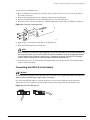
Connecting the EPS-LD to the Switch
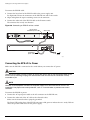
Connecting the EPS-LD to Power
Removing an EPS-LD unit
118
118
119
120
121
Installing and Removing the Internal 600 Watt AC Power Supply (15412)
Installing an Internal 600-Watt Power Supply
Removing an Internal Power Supply
121
122
123
Installing an External Power System for a Summit 400 Switch
Rack Mounting the EPS-T
Adding a Second EPS-160 to the EPS-T
Removing an EPS-160 from the EPS-T
124
125
126
126
Installing and Removing Summit48si AC Power Supplies
Power Supply Cords
Installing a Summit 48si AC Power Supply
Removing a Summit 48si AC Power Supply
127
127
127
128
Installing the AC Power Cable Retaining Bracket
Disconnecting a Power Cable with an Installed Cable Retaining Bracket
129
132
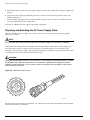
Installing the Summit48si Switch DC Power Supply
Preparing and Attaching the DC Power Supply Cable
Attaching the Connector to the DC Power Supply
132
134
135
Extreme Networks Consolidated "e" and "i" Series Hardware Installation Guide
Contents
Part 4
Chapter 6
Chapter 7
Chapter 8
Alpine Switch
Alpine 3800 Series Switch Models
Features
Port Connections
Power Supplies
Power Supply LEDs
Fans
139
140
140
141
142
Alpine 3808 Switch
142
Alpine 3804 Switch
144
Alpine 3802 Switch
Alpine 3802 Switch LEDs
Alpine 3802 Power Versions
146
148
148
Alpine 3800 Series Chassis Installation
Installation Summary
151
Safety Information
151
Installing the Chassis in a Rack
152
Grounding the Alpine 3800 Series Chassis
Grounding the Alpine 3802 Chassis
Grounding the Alpine 3804 or 3806 Chassis
155
156
156
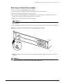
Removing the Chassis
157
Installing and Connecting Alpine 3800 Series Switch Power Supplies
Power Cords for the Alpine AC Power Supply
160
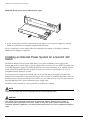
Installing an Alpine 3808 or Alpine 3804 AC Power Supply
160
Installing an Alpine 3808 or Alpine 3804 DC Power Supply
Selecting and Preparing DC Cabling
Installing the Power Supply
Attaching the Cables and Supplying Power
163
163
164
166
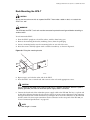
Supplying Power to the Alpine 3802 DC Power Supply
Selecting the Cabling
Attaching the Cables and Supplying Power
167
167
168
Verifying Successful Power Installation
168
Removing the Alpine 3808 or Alpine 3804 AC Power Supply
169
Removing the Alpine 3808 or Alpine 3804 DC Power Supply
170
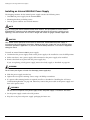
Installing the Alpine 3800 Series Switch External Power Supply
Rack-Mounting the EPS-LD Unit
Connecting the EPS-LD to the FM-32Pi Module
171
171
172
Extreme Networks Consolidated "e" and "i" Series Hardware Installation Guide
7
Contents
Removing an EPS-LD Unit
Chapter 9
174
Alpine 3800 Series Switch Management Module
SMMi Memory
SMMi LEDs
Chapter 10
Chapter 11
Part 5
Chapter 12
8
176
176
Installing SMMi Modules
Verifying the SMMi Installation
177
178
Replacing SMMi Modules
178
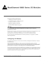
Alpine 3800 Series I/O Modules
Configuring I/O Modules
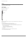
GM-4Ti Module
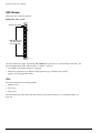
GM-4Xi Module
GM-4Si Module
GM-16X3 Module
GM-16T3 Module
FM-24Ti Module
FM-24SFi Module
FM-24MFi Module
FM-32Ti Module
FM-32Pi Module
FM-8Vi Module
WM-4T1i Module
WM-4E1i Module
WM-1T3i Module
I/O Module LEDs
181
183
184
186
187
189
191
193
194
195
196
198
200
201
202
202
Installing I/O Modules
204
Verifying the I/O Module Installation
LEDs
Displaying Slot Status Information
205
206
206
Installing External Power
206
Removing I/O Modules
206
Replacing the Alpine 3800 Series Switch Fan Tray
Removing the Alpine 3808 or Alpine 3804 Fan Tray
209
Installing the Alpine 3808 or Alpine 3804 Fan Tray
211
BlackDiamond Switch
BlackDiamond 6800 Series Switch Overview
Extreme Networks Consolidated "e" and "i" Series Hardware Installation Guide
Contents
Chapter 13
Chapter 14
Chapter 15
Features
Port Connections
Fans
Switch Connectivity and the Backplane
Packet Switching and Routing
215
216
217
217
217
BlackDiamond 6816 Switch
218
BlackDiamond 6808 Switch
222
BlackDiamond 6804 Switch
225
BlackDiamond Power Supplies
110 VAC Power Supplies
DC Power Supplies
227
229
230
Installing a BlackDiamond 6800 Series Switch Chassis
Installation Summary
233
Safety Information
233
Installing the Chassis
234
Grounding the BlackDiamond 6800 Series Chassis
238
Removing the Chassis
239
Installing and Connecting BlackDiamond 6800 Series Power Supplies
Preparing for Installation
241
Installing a BlackDiamond 6800 Series AC Power Supply
AC Power Cable and Plug
Verifying a Successful Installation
243
244
245
Replacing a BlackDiamond 6800 Series AC Power Supply
246
Installing a BlackDiamond 6800 Series DC Power Supply
Selecting and Preparing the DC Cabling
Attaching the Cable to the Lugs
Installing the Power Supply
Verifying a Successful Installation
248
248
249
250
250
Removing a BlackDiamond 6800 Series DC Power Supply
251
BlackDiamond 6800 Series Management Switch Fabric Module
Overview of the BlackDiamond Management Switch Fabric Module
MSM Activity
MSM Memory
MSM LEDs
253
255
256
257
Installing MSMs
Verifying the MSM Installation
257
260
Extreme Networks Consolidated "e" and "i" Series Hardware Installation Guide
9
Contents
Replacing MSMs
Chapter 16
Chapter 17
Part 6
Chapter 18
Part 7
Appendix A
BlackDiamond 6800 Series I/O Modules
Configuring I/O Modules
10GX3 Module
G8Ti Module
G8Xi Module
G12SXi Module
G16X3 Module
G24T3 Module
F48Ti Module
F96Ti Module
F32Fi Module
P3cSi, P3cMi, P12cSi, and P12cMi Modules
ARM
MPLS Module
A3cSi and A3cMi Modules
I/O Module LEDs
263
264
266
267
269
270
273
275
276
279
280
284
287
290
293
Installing I/O Modules
294
Verifying the I/O Module Installation
Displaying Slot Status Information
295
296
Replacing I/O Modules
296
Installing XENPAK Modules
297
Replacing the BlackDiamond 6800 Series Switch Fan Tray
Removing a BlackDiamond 6800 Series Fan Tray
299
Installing a BlackDiamond 6800 Series Fan Tray
301
Switch Operation
Initial Switch and Management Access
Connecting Equipment to the Console Port
305
Logging In for the First Time
306
Appendixes
Safety Information
Important Safety Information
Power
10
260
309
309
Extreme Networks Consolidated "e" and "i" Series Hardware Installation Guide
Contents
Power Cable
Fuse
Connections
Lithium Battery
Sicherheitshinweise (German)
Wichtige Sicherheitshinweise
Appendix B
Appendix C
Appendix D
310
311
311
312
313
313
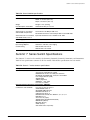
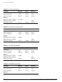
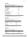
Switch Technical Specifications
Common Switch Specifications
Console Port Cables
315
316
Summit 200 Series Switch Specifications
318
Summit 300 Series Switch Specifications
Summit Switch Power Supply Specifications
322
323
Summit 400 Series Switch Specifications
326
Summit “i” Series Switch Specifications
327
Alpine 3800 Series Switch Specifications
330
BlackDiamond 6800 Series Switch Specifications
333
EPS-LD Power Supply Specifications
336
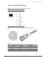
Power Connector Specifications
337
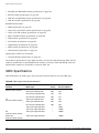
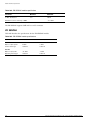
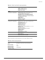
Module Technical Specifications
GBIC Specifications
340
Mini-GBIC Specifications
343
XENPAK Specifications
SR XENPAK
LR XENPAK
ER XENPAK
ZR XENPAK
LX4 XENPAK
CX4 XENPAK
344
345
345
345
346
347
348
Alpine Modules
348
BlackDiamond Modules
357
Common Module Specifications
368
Installing GBICs and Mini-GBICs
Installing GBICs
Safety Information
Preparing to Install or Replace a GBIC
Extreme Networks Consolidated "e" and "i" Series Hardware Installation Guide
369
371
371
11
Contents
Installing or Replacing a GBIC
372
Installing Mini-GBICs
Safety Information
Preparing to Install or Replace a Mini-GBIC
Installing or Replacing a Mini-GBIC
Appendix E
373
373
373
374
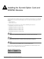
Installing the Summit Option Card and XENPAK Modules
Installing the Summit Option Card
378
Installing a XENPAK Optical Transceiver Module
379
Removing a XENPAK Module
381
Index
12
Extreme Networks Consolidated "e" and "i" Series Hardware Installation Guide
Preface
This preface provides an overview of this guide, describes guide conventions, and lists other
publications that might be useful.
NOTE
To ensure proper operation of your Extreme Networks equipment, read this guide before you install any
Extreme Networks equipment.
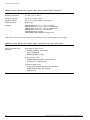
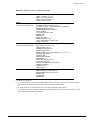
Introduction
This guide provides the information needed to install an Extreme Networks® “i” series or “e” series
Summit™ switch, Alpine® switch, or BlackDiamond® switch. Information is provided for the switch
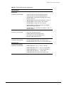
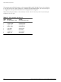
models shown in Table 1.
Table 1: Extreme Networks “i” and “e” series switch models
Switch Family
Switch Model
Summit 200 “e” series
•
Summit 200-24
•
Summit 200-24fx
•
Summit 200-48
•
Summit 300-24
•
Summit 300-48
•
Summit 400-24t
•
Summit 400-24p
•
Summit 400-48t
•
Summit1i
•
Summit5i
•
Summit7i
•
Summit48i
•
Summit48si
Summit 300 “e” series
Summit 400 “e” series
Summit “i” series
Extreme Networks Consolidated "e" and "i" Series Hardware Installation Guide
13
Preface
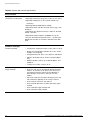
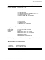
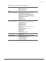
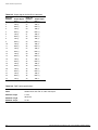
Table 1: Extreme Networks “i” and “e” series switch models (Continued)
Switch Family
Switch Model
Alpine 3800 “i” series
•
Alpine 3802
•
Alpine 3804
•
Alpine 3808
•
BlackDiamond 6804
•
BlackDiamond 6808
•
BlackDiamond 6816
BlackDiamond 6800 “i”
series
This guide contains information about site location, switch functionality, and switch operation. It is
intended for use by network administrators who are responsible for installing and setting up network
equipment. It assumes a basic working knowledge of:
• Local Area Networks (LANs)
• Ethernet concepts
• Ethernet switching and bridging concepts
• Routing concepts
• Simple Network Management Protocol (SNMP)
See the ExtremeWare Software User Guide for information about configuring an Extreme Networks switch.
NOTE
If the information in the Release Notes shipped with your switch differs from the information in this
guide, follow the Release Notes.
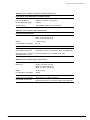
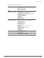
Conventions
Table 2 and Table 3 list conventions used throughout this guide.
Table 2: Notice icons
Icon
14
Notice Type
Alerts you to...
Note
Important features or instructions.
Caution
Risk of personal injury, system damage,
or loss of data.
Warning
Risk of severe personal injury.
Extreme Networks Consolidated "e" and "i" Series Hardware Installation Guide
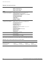
Related Publications
Table 3: Text conventions
Convention
Description
Screen displays
This typeface represents information as it appears on the screen,
or command syntax.
Screen displays bold
This typeface represents commands that you type.
The words “enter”
and “type”
When you see the word “enter” in this guide, you must type
something, and then press the Return or Enter key. Do not press
the Return or Enter key when an instruction simply says “type.”
[Key] names
Key names appear in text in one of two ways:
•
Referenced by their labels, such as “the Return key” or “the
Escape key”
•
Written with brackets, such as [Return] or [Esc]
If you must press two or more keys simultaneously, the key names
are linked with a plus sign (+). Example:
Press [Ctrl]+[Alt]+[Del].
Words in italicized type
Italics emphasize a point of information or denote new terms at the
place where they are defined in the text.
Related Publications
The Extreme Networks switch documentation set includes:
• Extreme Networks Consolidated “i” and “e” Series Hardware Installation Guide (this guide)
• ExtremeWare Software User Guide
• ExtremeWare Software Command Reference Guide
• ExtremeWare Release Notes
Documentation for Extreme Networks products is available from the Extreme Networks website at the
following location:
http://www.extremenetworks.com/services/documentation/
You can select and download the following Extreme Networks documentation from the Documentation
section of the Services page:
• Release Notes (you must have a valid service contract to access the release notes)
• Software User Guides
• Hardware User Guides
• White Papers
• Troubleshooting Tools
• Preventive Maintenance
• Instructional Videos
• Archives
Extreme Networks Consolidated "e" and "i" Series Hardware Installation Guide
15
Preface
About This Guide
This guide describes how to prepare your site and how to install, maintain, and operate your Extreme
Networks switch. It contains information about features that are common to all switches, as well as
switch-specific features. This guide contains seven parts:
• Common Features—Describes features that are shared by the Extreme Networks family of switches.
This section describes software images, full-duplex support, management ports, and mini-GBIC and
GBIC modules.
• Site Planning—Describes how to evaluate, plan, and determine the location of your Extreme
Networks switch.
• Summit Switch—Describes the features that are specific to the Summit switch. This section provides
an overview of the Summit switches, information about model types, descriptions of features, and
installation instructions.
• Alpine Switch—Describes the features that are specific to the Alpine switch. This section provides an
overview of the Alpine switch, information about model types, descriptions of features, and
installation instructions.
• BlackDiamond Switch—Describes the features that are specific to the BlackDiamond switch. This
section provides an overview of the BlackDiamond switch, information about model types,
descriptions of features, and installation instructions.
• Switch Operation—Describes how to power on any Extreme Networks switch, verify the switch
installation, connect equipment to the console port, and log in to the switch for the first time.
• Appendixes—Include information about safety requirements, technical specifications, and
specialized installation instructions.
How To Use This Guide
Each chapter of this guide contains information about how to successfully operate your Extreme
Networks switch. The chapters with Summit, Alpine, or BlackDiamond in the titles contain information
that is applicable only to that family of switch. All other chapters are applicable to any Extreme
Networks “i” series or “e” series switches.
Switch-Specific Information
For switch-specific information, be sure to read the applicable switch-specific chapter. For example, if
you have a BlackDiamond switch and you need to remove and replace an I/O module, see “Replacing
I/O Modules” in Chapter 16 for details about how to remove and replace an I/O module in a
BlackDiamond chassis.
Common Information
For items applicable to any Extreme Networks switch, make sure you read the appropriate chapter. For
example, to learn how to prepare your site for installing your Extreme Networks equipment, see
Chapter 2, “Site Preparation.”
16
Extreme Networks Consolidated "e" and "i" Series Hardware Installation Guide
About This Guide
Reference Information
This guide contains appendixes that describe:
• Switch safety issues
• Switch specifications
• Module specifications
• Installation procedures for accessory equipment
Appendix A, “Safety Information” describes important safety issues such as power, power cables, and
fuses.
Appendix B, “Switch Technical Specifications” is organized according to the family of switch: Summit,
Alpine, and BlackDiamond. This appendix describes switch specifications such as physical dimensions,
weight, certifications, and power supply parameters. Information that is common to all “i” series and
“e” series switches is described at the end of the appendix.
Appendix C, “Module Technical Specifications” is organized according to the family of switch and
modules available for that switch, and describes module specifications such as physical dimensions,
weight, and standards. Information that is common to all “i” series and “e” series modules is described
at the end of the appendix.
Appendix D, “Installing GBICs and Mini-GBICs” describes how to install GIBICs and mini-GBCS in
Extreme Networks switches and modules.
Appendix E, “Installing the Summit Option Card and XENPAK Modules” describes how to install the
Summit Option Card and associated XENPAK modules to add high-performance uplink ports to the
switch.
Extreme Networks Consolidated "e" and "i" Series Hardware Installation Guide
17
Preface
18
Extreme Networks Consolidated "e" and "i" Series Hardware Installation Guide
Part 1
Common Features
1
Common Switch Features
This chapter describes the features that are shared in common by the Extreme Networks family of
switches. The following topics are described in detail:
• Software Images on page 21
• Full-Duplex Support on page 22
• Management Ports on page 22
• Mini-GBIC Type and Hardware/Software Support on page 23
• GBIC Type and Hardware/Software Support on page 23
Extreme Networks switches that run on ExtremeWare include three product families: the Summit series,
Alpine series, and BlackDiamond series. They are divided into the “i” series and “e” series switches,
based on the chipset used in the switches. Available in a range of physical sizes and configurations,
these switches provide a wide variety of connection types and network services support. The Summit
switches are self-contained units that offer fixed ports and slots for installing Gigabit Ethernet
Connectors (GBICs) and mini-GBICs. The Alpine and BlackDiamond switches are chassis-based
switches with slots for installing management modules and a wide variety of I/O modules.
The combination of BlackDiamond, Alpine, and Summit switches delivers a consistent end-to-end
network solution that provides a nonblocking architecture, wire-speed switching, wire-speed IP routing,
and policy-based Quality of Service (QoS).
Software Images
When you receive a new Extreme Networks switch, be aware that an ExtremeWare® software image and
a BootROM image have been preinstalled at the factory. To verify the software image you are running
on your switch, use the show version CLI command. The show version command displays the
hardware and software versions currently running on the switch. To ensure that you have the latest
software and BootROM image, go to the support login portion of the Technical Support page at:
http://www.extremenetworks.com/services/
If your switch is running ExtremeWare version 6.2 or later, the Power LED activity is different from
previous versions of ExtremeWare. All other LED activity is the same. See Table 4 for more information
about the Power LED activity on switches running ExtremeWare version 6.2 or later.
Extreme Networks Consolidated "e" and "i" Series Hardware Installation Guide
21
Common Switch Features
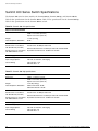
Table 4: Power LED activity for switches running ExtremeWare version 6.2 or later
LED
Color
Indicates
Power LED
Green
The indicated power supply unit (PSU) is powered up.
Amber
A PSU is installed, but not connected to power.
Off
The PSU is not receiving power or no PSU is present.
NOTE
If the information in the Release Notes that shipped with your switch differs from the information in this
guide, follow the Release Notes.
Full-Duplex Support
Extreme Networks switches provide full-duplex support for all ports. This means that frames can be
transmitted and received simultaneously, which, in effect, doubles the bandwidth that is available on a
link. Most ports on an Extreme Networks switch autonegotiate for half-duplex or full-duplex operation.
Gigabit Ethernet and 100BASE-FX ports operate in full-duplex mode only in accordance with technical
standards.
Management Ports
The 10/100BASE-TX Ethernet management port allows you to communicate directly to the CPU of the
switch. You can plug an Ethernet cable directly from your laptop into the management port. This
provides you with direct access into the switch and allows you to view and locally manage the switch
configurations.
Do not assign an in-band IP address to the Ethernet management port VLAN. The management port
VLAN is an out-of-band VLAN, so if it is assigned an in-band IP address (an address where the source
and destination are in the same subnet), the switch will treat it as a normal VLAN and attempt to route
traffic through it.
An Ethernet management port is located on the following Extreme Networks devices:
• Summit5i—The management port is located on the back of the switch.
• Summit7i—The management port is located on the front of the switch.
• Summit 400-48t—The management port is located on the back of the switch.
• Alpine—Switch Management Module (SMMi) for the Alpine series switch.
• BlackDiamond—Management Switch Fabric Module (MSM64i) for the BlackDiamond series switch.
Extreme Networks does not recommend that you use the management port to route traffic to any front
panel port on the switch. The management port is designed for switch management purposes.
22
Extreme Networks Consolidated "e" and "i" Series Hardware Installation Guide
Mini-GBIC Type and Hardware/Software Support
Mini-GBIC Type and Hardware/Software Support
The Summit48si and Summit “e” series switches, the BlackDiamond G16X3 module, and the Alpine
GM-16X3 module support the small form pluggable (SFP) GBIC, also known as the mini-GBIC. The
switches and the modules identify the type of mini-GBIC that is installed and verify that the mini-GBIC
is an Extreme Networks-certified mini-GBIC.
Mini-GBIC Types
Mini-GBICs are Class 1 laser devices that operate at 3.3 V.
The following types of mini-GBIC interfaces are available for these switches:
• SX mini-GBIC, which conforms to the 1000BASE-SX standard
• LX mini-GBIC, which conforms to the 1000BASE-LX standard
• ZX mini-GBIC, which conforms to the IEEE 802.3z standard
• 1000BX bi-directional mini-GBIC, which conforms to the IEEE 802.3ah 1000BASE-BX10 standard
— 1000BASE-BX-D, 1490 nm TX/1310 nm RX wavelength
— 1000BASE-BX-U, 1310 nm TX/1490 nm RX wavelength
Use only Extreme Networks-certified mini-GBICs, available from Extreme Networks, in the mini-GBIC
port of the switch or module.
Specifications for the mini-GBICs are in Appendix C, “Module Technical Specifications”.
Instructions to install mini-GBICs are in Appendix D, “Installing GBICs and Mini-GBICs”.
GBIC Type and Hardware/Software Support
Most Extreme Networks switches support two types of GBICs: the Parallel ID GBIC and the Serial ID
GBIC. The switch can identify the media type for the GBIC that is installed. Initial ExtremeWare
software versions do not support Serial ID GBICs. If Serial ID GBICs are installed in a switch with an
initial software release, the switch will not bring up the link on GBIC ports.
GBICs are available in the following media types:
• SX
• LX, LX70, and LX100
• ZX
• UTP
Specifications for the GBICs, including media types and optical specifications, are in Appendix C,
“Module Technical Specifications”. Instructions to install GBICs are in Appendix D, “Installing GBICs
and Mini-GBICs”.
NOTE
Extreme Networks optics are tested to work in all supported Extreme Networks switches. We
recommend that all customers use Extreme Networks optics in their Extreme Networks switches.
Extreme Networks Consolidated "e" and "i" Series Hardware Installation Guide
23
Common Switch Features
Extreme Networks assumes no liability for 3rd party optics. While Extreme Networks does not block 3rd
party optics, we cannot ensure that all 3rd party optics operate properly in all Extreme Networks
switches. The customer assumes all risks associated with using 3rd party optics in Extreme Networks
switches.
24
Extreme Networks Consolidated "e" and "i" Series Hardware Installation Guide
Part 2
Site Planning
2
Site Preparation
This chapter describes how to prepare your site for installing Extreme Networks equipment. It contains
information about environmental and cabling requirements, power requirements, and building and
electrical code organizations.
This chapter includes these sections:
• Planning Your Site on page 28
• Meeting Site Requirements on page 28
• Planning for Stacking on page 41
• Evaluating and Meeting Cable Requirements on page 44
• Meeting Power Requirements on page 49
• Applicable Industry Standards on page 53
• Planning for Optical Budgets on page 54
The requirements described in this chapter are intended for the system administrator, network
equipment technician, or network manager who is responsible for installing and managing the network
hardware. It assumes a working knowledge of local area network (LAN) operations, and a familiarity
with communications protocols that are used on interconnected LANs. Installation, maintenance, and
removal of a switch, chassis, or its components must be done by qualified service personnel only.
Qualified service personnel have had appropriate technical training and experience that is necessary to
be aware of the hazards to which they are exposed when performing a task and of measures to
minimize the danger to themselves or other people.
By carefully planning your site, you can maximize the performance of your existing network and ensure
that it is ready to migrate to future networking technologies.
To learn more about safety issues and to ensure safety compliance, see Appendix A.
WARNING!
Read the safety information in Appendix A thoroughly before installing your Extreme Networks switch.
Failure to follow this safety information can lead to personal injury or damage to the equipment.
Extreme Networks Consolidated "e" and "i" Series Hardware Installation Guide
27
Site Preparation
Planning Your Site
To install your equipment successfully, you should plan your site carefully. The site planning process
has four major steps:
Step 1: Meeting Site Requirements
Your physical installation site must meet several requirements for a safe and successful installation:
• Building and electrical code requirements
• Environmental, safety, and thermal requirements for the equipment you plan to install
• Distribution rack requirements
Step 2: Planning for Stacking (Summit “e” Series Only)
If you will be installing Summit “e” series switches in a stacked configuration, make sure you have the
appropriate cables for the interconnections. To use the dedicated stacking ports on the back of the
Summit 400 series switches, you must have a special cable that is available from Extreme Networks.
Step 3: Evaluating and Meeting Cable Requirements
After examining your physical site and ensuring all environment requirements are met, you should
evaluate and compare your existing cable plant with the requirements of the Extreme Networks
equipment to determine if you need to install new cables (or cabling).
Step 4: Meeting Power Requirements
To run your equipment safely, you must meet the specific power requirements for the Extreme
Networks equipment that you plan to install.
NOTE
Review the safety information before you begin installing the equipment. be sure to follow all safety
recommendations during the installation process.
Meeting Site Requirements
This section addresses the various requirements to consider when preparing your installation site,
including:
• Operating Environment Requirements
• Rack Specifications and Recommendations
28
Extreme Networks Consolidated "e" and "i" Series Hardware Installation Guide
Meeting Site Requirements
Operating Environment Requirements
Verify that your site meets all environmental and safety requirements.
Virtually all areas of the United States are regulated by building codes and standards. During the early
planning stages of installing or modifying your LAN, it is important that you develop a thorough
understanding of the regulations that pertain to your location and industry.
Building and Electrical Codes
Building and electrical codes vary depending on your location. Comply with all code specifications
when planning your site and installing cable. The following sections are provided as a resource to
obtain additional information.
Three major building codes are:
• Uniform Building Code—produced by the International Conference of Building Officials (ICBO);
5360 South Workman Mill Road; Whittier, California 90601 USA. www.icbo.org
• BOCA Basic Building Code—produced by the Building Officials and Code Administrators (BOCA)
International, Inc.; 4051 West Flossmoor Road; Country Club Hills, Illinois 60478 USA.
www.bocai.org
• Standard Building Code (SBC)—produced by the Southern Building Code Congress International,
Inc.; 900 Montclair Road; Birmingham, Alabama 35213 USA. www.sbcci.org
Five authorities on electrical codes are:
• National Electrical Code (NEC) Classification (USA only)—a recognized authority on safe electrical
wiring. Federal, state, and local governments use NEC standards to establish their own laws,
ordinances, and codes on wiring specifications. The NEC classification is published by the National
Fire Protection Association (NFPA). The address is NFPA; 1 Batterymarch Park; Quincy,
Massachusetts 02269 USA. www.nfpa.org
• Underwriters’ Laboratory (UL) (USA only)—an independent research and testing laboratory. UL
evaluates the performance and capability of electrical wiring and equipment to determine whether
they meet certain safety standards when properly used. Acceptance is usually indicated by the
words “UL Approved” or “UL Listed.” The address is UL; 333 Pfingsten Road; Northbrook, Illinois
60062-2096 USA. www.ul.com
• National Electrical Manufacturing Association (NEMA) (USA only)—an organization of electrical
product manufacturers. Members develop consensus standards for cables, wiring, and electrical
components. The address is NEMA; 2101 L Street N.W.; Washington, D.C. 20037 USA.
www.nema.org
• Electronics Industry Association (EIA)—a trade association that develops technical standards,
disseminates marketing data, and maintains contact with government agencies in matters relating to
the electronics industry. The address is EIA; 2001 Eye Street N.W.; Washington, D.C. 20006 USA.
www.eia.org
• Federal Communications Commission (FCC)—a commission that regulates all interstate and foreign
electrical communication systems that originate in the United States according to the
Communications Act of 1934. The FCC regulates all U.S. telephone and cable systems. The address is
FCC; 1919 M Street N.W.; Washington, D.C. 20554 USA.
Extreme Networks Consolidated "e" and "i" Series Hardware Installation Guide
29
Site Preparation
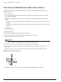
Wiring Closet Considerations
You should consider the following recommendations for your wiring closet:
• Ensure that your system is easily accessible for installation and service. See “Rack Specifications and
Recommendations” on page 39 for specific recommendations.
• Use appropriate AC or DC power for your switch. Foe more information about power requirements,
see “Meeting Power Requirements” on page 49.
• Use a vinyl floor covering in your wiring closet. (Concrete floors accumulate dust, and carpets can
cause static electricity.)
• Prevent unauthorized access to wiring closets by providing door locks. Install the equipment in a
secured, enclosed, and restricted-access area, ensuring that only qualified service personnel have
access to the equipment.
• Provide adequate overhead lighting for easy maintenance.
• Ensure that each wiring closet has a suitable ground. All distribution racks and equipment installed
in the closet should be grounded.
• Ensure that all system environmental requirements are met, such as ambient temperature and
humidity.
NOTE
Extreme Networks recommends that you consult an electrical contractor for commercial building and
wiring specifications.
Temperature. Extreme Networks equipment generates a significant amount of heat. It is essential that
you provide a temperature-controlled environment for both performance and safety.
Install the equipment only in a temperature- and humidity-controlled indoor area that is free of airborne
materials that can conduct electricity. Too much humidity can cause a fire. Too little humidity can
produce electrical shock and fire.
The following are some general thermal recommendations for your wiring closet:
• Ensure that the ventilation in the wiring closet is adequate to maintain a temperature below 104° F
(40° C).
• Install a reliable air conditioning and ventilation system.
• Keep the ventilation in the wiring closet running during nonbusiness hours; otherwise, the
equipment can overheat.
• Maintain ambient operating temperature: 32° to 104° F (0° to 40° C)
• Maintain storage Temperature: -40° to 158° F (-40° to 70° C)
NOTE
Like all electrical equipment, switch product lifetimes degrade with increased temperature. If possible,
temperatures should be kept at approximately 78° F (25° C) or lower.
For more information about monitoring temperature and preventing overheating conditions, see
“Monitoring Airflow Temperatures and Handling Overheating” on page 36.
30
Extreme Networks Consolidated "e" and "i" Series Hardware Installation Guide
Meeting Site Requirements
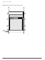
BlackDiamond 6816 Spacing Requirements. Due to chassis-to-chassis heating, Extreme Networks
recommends placing no more than three BlackDiamond 6816 chassis next to each other.
The following are some general recommendations for installing your BlackDiamond 6816 chassis:
• A minimum of 17.32 inches (44 cm) between each set of three BlackDiamond 6816 chassis.
Or
• Place front-back cooled equipment, such as a BlackDiamond 6808 chassis, between each set of three
BlackDiamond 6816 chassis.
Or
• Place patch panels, which are used to patch cables together, between each set of three BlackDiamond
6816 chassis. A patch panel does not require any power and does not generate any heat.
NOTE
Up to five adjacent BlackDiamond 6816 chassis will continue to function without safety concerns.
However, product lifetime may degrade with continued exposure to high temperatures in close proximity
and long term reliability may be compromised.
Airflow Requirements. Cooling of an Extreme Networks switch requires proper airflow through the
chassis. Make sure there is space around the installed switch for airflow and that cables or other
equipment do not block the air intake or outflow vents on the Extreme Networks switches. It is best to
have 3 to 5 inches (7.62 to 12.7 cm) of clear space in front of the air intake and outflow vents on the
switches. Depending on other conditions in the equipment room or wiring closet, it may be possible to
install the switches closer to each other. Consult your Extreme Networks Customer Support
representative for guidance.
For proper airflow through the switch, leave clear space around the switch as follows:
• Summit family of switches—left and right sides of the switch
• Alpine 3800 series chassis—left and right sides of the switch
• BlackDiamond 6816 and 6804 chassis—around the entire chassis (front, rear, and sides)
• BlackDiamond 6808 chassis—front and rear of the chassis
The airflow of the Summit family of switches moves from the left side of the switch to the right side of
the switch, or from the right side of the switch to the left side of the switch depending on the model.
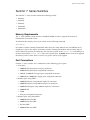
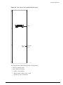
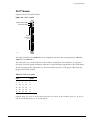
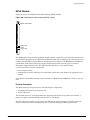
The airflow of the Alpine 3808 moves through the power supplies and is independent of the airflow
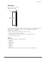
through the chassis as shown in Figure 1. For example, if the power supply fans fail, the airflow
through the module area of the chassis will not cool down the power supplies.
• Airflow for cooling power supplies enters the top of the chassis and moves left to right as you face
the chassis.
• Airflow for cooling modules moves left to right as you face the chassis.
Extreme Networks Consolidated "e" and "i" Series Hardware Installation Guide
31
Site Preparation
Figure 1: Airflow through the Alpine 3808 chassis
Airflow
through
power
supplies
Airflow
through
chassis
Airflow
through
chassis
38_air8
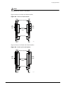
The airflow of the Alpine 3804 and Alpine 3802 moves from the left side of the chassis to the right side
of the chassis as shown in Figure 2 and Figure 3.
• Airflow for cooling power supplies moves left to right as you face the chassis.
• Airflow for cooling modules moves left to right as you face the chassis.
Figure 2: Airflow through the Alpine 3804 chassis
Airflow
through
chassis
Airflow
through
chassis
38_air4
32
Extreme Networks Consolidated "e" and "i" Series Hardware Installation Guide
Meeting Site Requirements
Figure 3: Airflow through the Alpine 3802 chassis
Airflow
through
chassis
Airflow
through
chassis
3802air
Extreme Networks Consolidated "e" and "i" Series Hardware Installation Guide
33
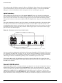
Site Preparation
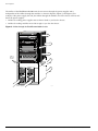
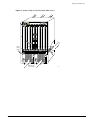
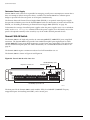
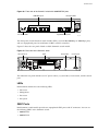
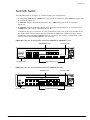
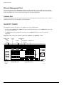
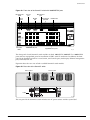
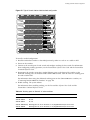
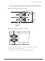
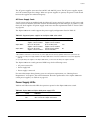
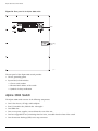
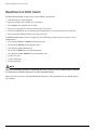
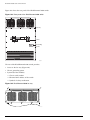
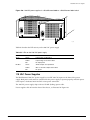
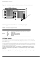
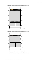
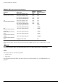
The airflow of the BlackDiamond 6800 series chassis moves through the power supplies and is
independent of the airflow through the modules as shown in Figure 4, Figure 5, and Figure 6. For
example, if the power supply fans fail, the airflow through the module area of the chassis will not cool
down the power supplies.
• Airflow for cooling power supplies moves front to back as you face the chassis.
• Airflow for cooling modules moves left to right as you face the chassis.
Figure 4: Airflow through the BlackDiamond 6816 chassis
1
2
3
4
5
6
7
8
A
B
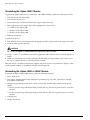
C
D
9
10
11
12
Airflow
through
chassis
13
14
15
16
Airflow through
power supplies
34
BD_032
Extreme Networks Consolidated "e" and "i" Series Hardware Installation Guide
Meeting Site Requirements
Figure 5: Airflow through the BlackDiamond 6808 chassis
1
2
3
4
A
B
50015
50015
5
6
7
8
Airflow
through
chassis
POWER
POWER
DC OUT
AC IN
50021
Airflow through
power supplies
Extreme Networks Consolidated "e" and "i" Series Hardware Installation Guide
DC OUT
AC IN
50021
BD_027
35
Site Preparation
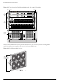
Figure 6: Airflow through the BlackDiamond 6804 chassis
Airflow
from
fan tray
Airflow
through
modules
Airflow through
power supplies
6804air
Humidity. Operating humidity should be kept between 10 and 95% relative humidity (noncondensing).
Monitoring Airflow Temperatures and Handling Overheating
ExtremeWare provides a temperature logging function that allows the regular capturing of system
temperature to the system log. The enable logging-temperature command reports the internal
temperature (as reported in the temperature sensors on the active master MSM in the chassis) in the
system and logs temperature readings hourly in the system log. Additionally, general status is reported
through the show switch command. For more information about using these commands, see the
ExtremeWare Software User Guide and the ExtremeWare Software Command Reference Guide.
The active master MSM reports the temperature captured by ExtremeWare. While temperature sensors
are located on every module in the system, only the active MSM master controls the reporting for the
system. An overheating condition will be reported if a system temperature sensor detects a temperature
of 55° C or above.
NOTE
A module’s temperature sensor reading is normally +/- 5° C compared to the ambient temperature
measured around the equipment.
Automatic Shutdown in an Overheating Condition. The power supply controls the overheating
shutdown condition in the system. The power will shut down at approximately 85° C (+/- 5° C) as
reported on an independent temperature sensor within the power supply.
36
Extreme Networks Consolidated "e" and "i" Series Hardware Installation Guide
Meeting Site Requirements
NOTE
Note that automatic shutdown is based solely on the power supply temperature sensor and is not based
on the temperature sensor of the MSM. The power supply temperature sensor readings are not visible
through the ExtremeWare command set. This protection is designed to prevent thermal runaway
conditions, and does not ensure the protection of the system modules. Internal temperatures above
55° C (+/- 5° C) can produce a decline in the long-term reliability of the system overall.
The system will recover automatically once the temperature has dropped to 80° C as tracked by the
independent temperature sensor within the power supply. The temperature sensor remains active when
the system is in a shutdown state.
System Alarms in an Overheating Condition. Extreme supports the following SNMP alarms to
report overheating conditions:
• Over Temperature Alarm: This trap sends notification of an overheating condition, but takes no
action. The alarm threshold is fixed at 55° C; however, you can control the alarm by turning it ON or
OFF.
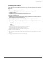
• Overheat: This is a trap sent before the system is taken offline. It indicates that the onboard
temperature sensor has reported an overheating condition. The system will shut down until the unit
has cooled sufficiently. A cold start trap will be issued when the unit has come back online.
You can use the ExtremeWare command set to capture temperature logs on an hourly basis. However,
the traps on the system are not configurable.
You can use these traps to trigger an SNMP management platform to react with an external program to
perform programmed actions to remedy the situation. For example, you could shut down power by
using a remote power management device available from a third party. The actions performed depend
on both the capability of the management platform and any third-party device that can be set to control
the flow of power to the switch.
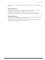
Monitoring Overheating Symptoms. In general, any system reporting temperatures above 40° C
should be closely monitored. You should take the following actions:
• Use the ExtremeWare command set to enable temperature logging and monitor for any rises or
decline in temperature in the system logs.
• Ensure proper environment conditions as described earlier in this section.
Environmental conditions with especially poor airflow can severely impact system performance.
Numerous racks to the left and right of the system being monitored can result in the system being
cooled by the exhaust of another system or influenced by the heat emitted from the adjoining
systems. In addition, enclosed racks can prevent proper airflow. Poor environment placement of this
type can typically result in as much as a 10° C increase to the ambient temperature (that is, the
temperature of the environment around the switch) being fed to the system.
• Check airflow into and out of the system, ensuring appropriate spacing for proper air circulation.
• Verify that any additional equipment installation has not blocked airflow.
• Check fans to ensure that there has not been a slowdown or failure of fan operation.
• Ensure that proper blank faceplates are used for all open slots.
Openings in a chassis can result in air eddies in the system, resulting in regions of the system
operating at higher temperatures.
Extreme Networks Consolidated "e" and "i" Series Hardware Installation Guide
37
Site Preparation
Excessive temperature can cause various symptoms to appear on a unit. Once a system has failed due to
overheating, it should be carefully monitored to ensure that a system component or module has not
been compromised. The following symptoms can indicate additional problems that require further
analysis:
• Checksum errors: Increased temperature can damage sensitive components resulting in an increased
degradation of internal circuit reliability. This could result in errors being reported within the switch
fabric itself. Checksum errors of various types (e.g., p-bus, int, external, CPU) can start appearing in
small quantities at temperatures in excess of 40° C as reported by ExtremeWare commands.
• System reboot: The system may reboot to recover to a normal state based on the hardware
configuration. A reboot considered in isolation is not a common symptom of temperature damage;
however, viewed in conjunction with excessive error reporting it may indicate such damage.
Rebooting can occur if checksum errors result in an interruption of core switch command processing.
• Decreased System Reliability: While immediate issues may not arise on system recovery, an
overheating condition within a system may affect the system’s long-term reliability.
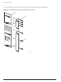
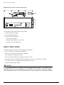
Electrostatic Discharge (ESD)
Your system must be protected from static electricity. Take the following measures to ensure optimum
system performance:
• Keep relative humidity at 50 to 70%.
• Remove materials that can cause electrostatic generation (such as synthetic resins) from the wiring
closet. Check the appropriateness of floor mats and flooring.
• Connect conductors (metals, etc.) to ground, using dedicated grounding lines.
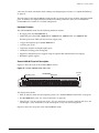
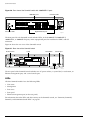
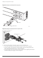
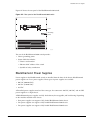
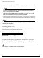
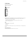
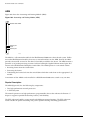
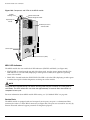
• Use electrostatically safe equipment and the ESD straps that are provided with your equipment. All
Alpine and BlackDiamond switches come with ESD wrist strap connectors and wrist straps as
shown in Figure 7.
38
Extreme Networks Consolidated "e" and "i" Series Hardware Installation Guide
Meeting Site Requirements
Figure 7: Using an ESD wrist strap when handling switch components
1
2
3
4
A
B
50015
50015
5
6
7
8
ESD strap
connector
Connected
wrist strap
POWER
POWER
DC OUT
AC IN
50020
DC OUT
AC IN
50020
SPG_003
Rack Specifications and Recommendations
Racks should conform to conventional standards. In the United States, use EIA Standard RS-310C:
Racks, Panels, and Associated Equipment. In countries other than the United States, use IEC Standard
297. In addition, verify that your rack meets the basic mechanical and space requirements that are
described in this section.
Mechanical Recommendations for the Rack
Use distribution racks that meet the following mechanical recommendations:
• Use an open style, 19-inch (48.26 cm) rack to facilitate easy maintenance and to provide proper
ventilation.
• The rack should use the universal mounting rail hole pattern that is identified in IEC Standard 297.
• The mounting holes should be flush with the rails to accommodate the chassis.
• Use a rack made of steel or aluminum.
Extreme Networks Consolidated "e" and "i" Series Hardware Installation Guide
39
Site Preparation
• Install equipment into the lower half of the rack first to avoid making the rack top-heavy.
• The rack should support approximately 600 pounds (272 kilograms).
Protective Grounding for the Rack (Alpine and BlackDiamond Switches)
Adequate grounding for Summit switches is provided through the power cord. No additional
grounding of the rack is required. For Alpine and BlackDiamond switches, follow the recommendations
in this section.
Use a rack grounding kit and a ground conductor that is carried back to earth or to another suitable
building ground.
All Extreme Networks switches are designed with mounting brackets that provide solid metal-to-metal
connection to the rack. If you do not use equipment racks, you can attach wiring terminals directly to
the mounting brackets for appropriate grounding. Alpine and BlackDiamond products have grounding
terminals that are mounted on the back of the chassis.
At a minimum, follow these guidelines:
• Ground equipment racks to earth ground.
— Use the same gauge copper wire for grounding as that used for the power input cable.
— Drill and tap wire terminals to equipment racks.
— Position the earth ground as close to the equipment rack as possible to maintain the shortest
wiring distance possible.
— Use a ground impedance tester or micro-ohm meter to test the quality of earth ground connection
at the chassis. This will ensure good grounding between the chassis, rack, and earth ground.
NOTE
Because building codes vary worldwide, Extreme Networks strongly recommends that you consult an
electrical contractor to ensure proper equipment grounding is in place for your specific installation.
• Ground DC power supplies to earth ground by using the grounding terminals provided.
Space Requirements for the Rack
Provide enough space in front of and behind the switch so that you can service it easily. Allow a
minimum of 48 inches (122 cm) in front of the rack and 24 inches (61 cm) behind the rack. When using a
relay rack, provide a minimum of 24 inches (61 cm) of space behind the mounted equipment. Extra
room on each side is optional.
NOTE
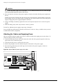
Install your equipment rack near an easily accessible power outlet. When you need to disconnect the
power cable from your switch, remove it first from the power source and then from the switch.
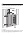
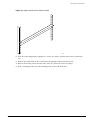
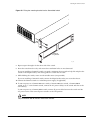
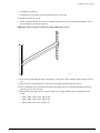
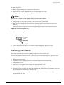
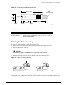
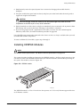
Securing the Rack
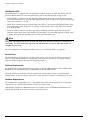
The rack should be attached to the wiring closet floor with 3/8 inch (9.5 mm) lag screws or equivalent
hardware. The floor under the rack should be level within 3/16 inch
(5 mm). Use a floor-leveling cement compound if necessary or bolt the racks to the floor as shown in
Figure 8.
40
Extreme Networks Consolidated "e" and "i" Series Hardware Installation Guide
Planning for Stacking
Figure 8: Properly secured rack
Secure to floor
with 3/8 inch lag screws or bolts
SPG_007
Brace open distribution racks if the channel thickness is less than 1/4 inch (6.4 mm).
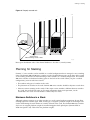
Planning for Stacking
Summit “e” series switches can be installed in a stacked configuration that is managed as one switching
entity. The Summit 200 and 300 series switches use the Gigabit Ethernet ports on the front of the switch
as the stacking connectors for interconnecting to other switches in a stacked configuration. The Summit
400 series switches use dedicated stacking ports on the back of the switch. When you plan a stacked
configuration, you must take into account:
• The number and types of switches in the stack.
• The placement of switches in the stack. Summit 400 series switches should be adjacent to each other.
• Software versions running on the switch. If the major version number is different between switches
in a stack, the stack will not come up. For more information about stack operation, see the
ExtremeWare User Guide and ExtremeWare Command Reference Guide.
Maximum Switches in a Stack
Although software supports up to eight switches in a stack, certain hardware restrictions do not allow
stacking eight units of some types. Each switch type is assigned a platform weight or slot budget to be
used in determining the total number of switches allowed in the stack. The Summit 400 series switches
also have an assigned platform weight for installed 10-gigabit dual uplink ports (Summit XEN or
XGM-2xn Option Card). Table 5 lists the platform weights.
Extreme Networks Consolidated "e" and "i" Series Hardware Installation Guide
41
Site Preparation
Table 5: Summit switch platform weights for stacking
Platform
Platform Weight
Summit 200-24
1
Summit 200-24fx
1
Summit 200-48
2
Summit 300-24
1
Summit 400-24
2
Summit 400-48
4
10-gigabit option card
2
The sum of all platform weights in the stack must be no greater than 32. The total number of switches
must be no greater than 8.
Example 1: How many Summit 400-48t switches with no installed XEN or XGM 10-Gigabit option cards
can be in a stack?
Platform weight for the Summit 400-48t = 4
Let the number of switches = x
4 * x = 32
x = 32 ÷ 4 = 8
The maximum number of Summit 400-48t switches in a stack is 8.
Example 2: How many Summit 400-48t switches with installed XEN or XGM 10-Gigabit option cards
can be in a stack?
Platform weight for the Summit 400-48t = 4
Platform weight for one 10-gigabit option card = 2
Let the number of switches = x
(4 * x) + (2 * 2) = 32
4 * x = 28
x = 28 ÷ 4 = 7
The maximum number of Summit 400-48t switches with installed 10-Gigabit option cards in a stack is 7.
Example 3: Stacking eight Summit 400 series switches with Summit XEN option cards.
In a stack with two Summit 400-48 switches containing Summit XEN cards to provide high-speed
20-Gbps uplinks, how many Summit 400-24 switches can be added to the stack?
Platform weight for Summit 400-48 = 4
Platform weight for Summit XEN option card = 2
Platform weight for the Summit 400-24 = 2
Let the supported number of slots of Summit 400-24 switches in this configuration = y
42
Extreme Networks Consolidated "e" and "i" Series Hardware Installation Guide
Planning for Stacking
Sum of all platform weights:
[2 * (weight of Summit 400-48)] + [2 * (weight of XEN card)] + [y * (weight ot Summit 400-24)] ≤ 32
(2 * 4) + (2 * 2) + (y * 2) ≤ 32
y ≤ 10
Because software supports only up to eight switches in a stack, the total maximum number of
Summit 400 series switches in a stack is 8. Two Summit 400-48 switches are already installed; therefore,
six Summit 400-24 switches can be in the stack.
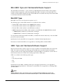
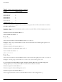
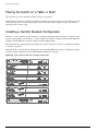
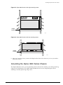
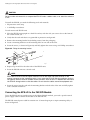
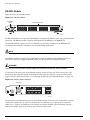
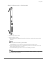
Planning Switch Placement in the Rack
The Summit 200 and 300 series switches use the 1-gigabit Ethernet ports on the front of the switch as
stacking ports. The Summit 400 series switches have dedicated stacking ports on the back of the switch.
If you are mixing switch types in a stack, keep the following in mind:
• If only Summit 200 and 300 series switches are in the stack, all stacking connections happen at the
front of the switch using the 1-gigabit Ethernet ports.
• If only Summit 400 series switches are in the stack, stacking connections happen at the back of the
switch using the Extreme Networks-specified stacking cable and the dedicated stacking ports.
• Stacking Summit 200 or 300 series switches with Summit 400 series switches is not supported.
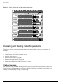
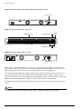
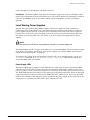
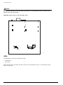
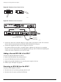
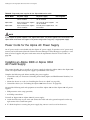
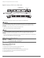
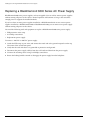
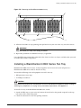
Figure 9 shows a typical stacked configuration using Summit 400 series switches, and Figure 9 shows a
typical stacked configuration using Summit 200 and 300 series switches. For more information about
stacking, see the ExtremeWare User Guide.
Figure 9: Typical Summit 400 series stacked configuration
EW75001
Extreme Networks Consolidated "e" and "i" Series Hardware Installation Guide
43
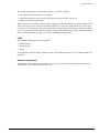
Site Preparation
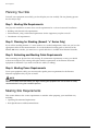
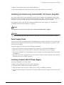
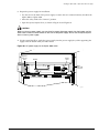
Figure 10: Typical Summit 200 and 300 stacked configuration
EW75002
Evaluating and Meeting Cable Requirements
This section addresses requirements for the cables used when installing your network equipment. It
includes:
• Cabling Standards on page 44
• Cable Labeling and Record Keeping on page 45
• Installing Cable on page 45
• RJ-45 Connector Jackets on page 48
• Radio Frequency Interference on page 48
• Making Network Interface Cable Connections on page 49
Cabling Standards
We recommend using the BICSI (Building Industry Consulting Service International) RCDD (Registered
Communications Distribution Designer), which is globally recognized as a standard in site planning and
cabling. For information, go to http://www.bicsi.org
44
Extreme Networks Consolidated "e" and "i" Series Hardware Installation Guide
Evaluating and Meeting Cable Requirements
Cable Labeling and Record Keeping
A reliable cable labeling system is essential when planning and installing a network. Maintaining
accurate records helps you to:
• Relocate devices easily.
• Make changes quickly.
• Isolate faults in the distribution system.
• Locate the opposite end of any cable.
• Know the types of network devices that your cabling infrastructure can support.
Consider the following recommendations when setting up a cable labeling system suitable for your
installation:
• Identify cables by securely attaching a label to all cable ends.
• Assign a unique block of sequential numbers to the group of cables that run between each pair of
wiring closets.
• Assign a unique identification number to each distribution rack.
• Identify all wiring closets by labeling the front panel of your Extreme Networks equipment and
other hardware.
• Keep accurate and current cable identification records.
• Post records near each distribution rack. Include the following cable drop information: the cable
source, destination, and jumper location.
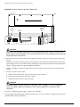
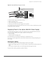
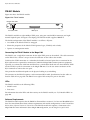
Installing Cable
Consider the following recommendations when you connect cable to your network equipment:
• Examine cable for cuts, bends, and nicks.
• Support cable using a cable manager that is mounted above connectors to avoid unnecessary weight
on the cable bundles.
• Use cable managers to route cable bundles to the left and right of the network equipment to
maximize accessibility to the connectors.
• Provide enough slack—approximately 2 to 3 inches (5.08-7.62 cm)— to provide proper strain relief as
shown in Figure 11.
• Bundle cable using velcro straps to avoid injuring cables.
• If you build your own cable, ensure that cable is properly crimped.
• When installing a patch panel using twisted pair wiring, untwist no more than 1 inch (2.54 cm) of
the cable to avoid RF interference.
• When required for safety and fire rating requirements, use plenum-rated cable. See your local
building codes for determining when it is appropriate to use plenum-rated cable, or refer to IEC
standard 850.
• Keep all ports and connectors free of dust.
Extreme Networks Consolidated "e" and "i" Series Hardware Installation Guide
45
Site Preparation
NOTE
Unshielded twisted pair (UTP) cable can build up ESD charges when being pulled into a new
installation. Before installing category 5 UTP cables, discharge ESD from the cable by plugging it into a
port on a switch or any network device that is not powered on.
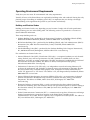
Figure 11: Properly installed and bundled cable
Cable managers supporting
and directing cables
Proper
bundling
of cables
Adequate
slack, and
bend radius
SPG_008
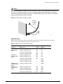
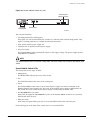
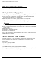
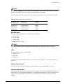
Fiber Optic Cable
Fiber optic cable must be treated gently during installation. Every cable has a minimum bend radius, for
example, and fibers will be damaged if the cables are bent too sharply. It is also important not to stretch
the cable during installation. We recommend that the bend radius for fiber optic cable equals 2-inch
(5.08 cm) minimum for each 90 degree turn as shown in Figure 12.
46
Extreme Networks Consolidated "e" and "i" Series Hardware Installation Guide
Evaluating and Meeting Cable Requirements
NOTE
Kinks and sharp bends can destroy or impair the cable’s ability to convey light pulses accurately from
one end of the cable to the other. Use care in dressing the optical-fiber cables: provide satisfactory
strain relief to support the cable and maintain an adequate bend radius at all cable turns, particularly
where the cable connects to the I/O module.
Figure 12: Bend radius for fiber optic cable
Minimum
2 in. (5.08cm)
radius
in 90˚ bend
90˚
Optical fiber cable
SPG_002
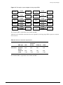
Cable Distances
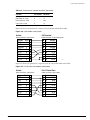
Table 6 shows cable media types and maximum distances that support reliable transmission in
accordance with international standards except where noted.
Table 6: Media types and maximum distances
Standard
Media Type
Mhz•Km
Rating
Maximum Distance
(Meters)
1000BASE-SX
(850 nm optical
window)
50/125 µm multimode fiber
400
500
50/125 µm multimode fiber
500
550
62.5/125 µm multimode fiber
160
220
62.5/125 µm multimode fiber
200
275
50/125 µm multimode fiber
400
550
50/125 µm multimode fiber
500
550
62.5/125 µm multimode fiber
500
550
10/125 µm single-mode fiber
–
5,000
10/125 µm single-mode fiber*
–
10,000
1000BASE-LX70
(1550 nm optical
window)
10/125 µm single-mode fiber
–
70,000
100BASE-FX
(1300 nm optical
window)
50/125 µm multimode fiber
400
2000
50/125 µm multimode fiber
500
2000
62.5/125 µm multimode fiber
400
2000
62.5/125 µm multimode fiber
500
2000
1000BASE-LX
(1300 nm optical
window)
Extreme Networks Consolidated "e" and "i" Series Hardware Installation Guide
47
Site Preparation
Table 6: Media types and maximum distances (Continued)
Mhz•Km
Rating
Maximum Distance
(Meters)
Standard
Media Type
1000BASE-T
Category 5 and higher UTP cable
–
100
100BASE-TX
Category 5 and higher UTP cable
–
100
10BASE-T
Category 3 and higher UTP cable
–
100
*
Proprietary to Extreme Networks. Connections between two Extreme Networks 1000BASE-LX interfaces that use 10/125 µm
single-mode fiber can use a maximum distance of 10,000 meters.
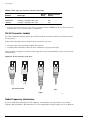
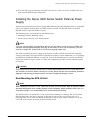
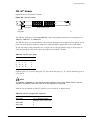
RJ-45 Connector Jackets
Use cable with RJ-45 connector jackets that are flush with the connector or that have connectors with a
no-snag feature.
Using cable with jackets that are wider than the connectors can cause:
• Connectors that are not properly aligned with the port.
• Crowded cable installation, which can cause connectors to pop out of the port.
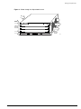
Figure 13 shows examples of connector jacket types that are not recommended as well as those that are
recommended.
Figure 13: RJ-45 connector jacket types
Not recommended
Best
Better
0.1" = 1mm actual
39.37% : 254%
SPG_001
Radio Frequency Interference
If you use unshielded twisted pair (UTP) cabling in an installation, take precautions to avoid radio
frequency (RF) interference. RF interference can cause degradation of signal quality, and, in an Ethernet
48
Extreme Networks Consolidated "e" and "i" Series Hardware Installation Guide
Meeting Power Requirements
network environment, can cause excessive collisions, loss of link status, or other physical layer problems
that can lead to poor performance or loss of communication.
To prevent RF interference, avoid the following devices or situations:
• Attaching UTP cable to AC power cables
• Routing UTP cable near antennas, such as a Ham radio antenna
• Routing UTP cable near equipment that could exhibit RF interference, such as:
— ARC welding equipment
— Electrical motors that contain coils
— Air conditioner units
— Electrical transformers
In areas or applications where these situations cannot be avoided, use fiber optic cabling or shielded
twisted pair cabling (STP).
NOTE
Because harmonics can appear on the neutral line of a typical three-phase power circuit, Extreme
Networks recommends using a harmonics meter in new installations.
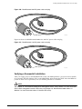
Making Network Interface Cable Connections
Use the appropriate type of cable to connect the ports of your switch to another switch or router.
Working carefully, one port at a time, follow these steps:
1 Verify that you have identified the correct cable for the port.
2 Use an alcohol wipe or other appropriate cleaning agent to clean the cable connectors; make sure
they are free of dust, oil, and other contaminants.
3 If you are using optical-fiber cable, align the transmit (Tx) and receive (Rx) connectors with the
correct corresponding connectors on the switch or the I/O module.
On the ATM and PoS modules, the transmit (Tx) connector on each port is the top connector.
4 Press the cable connectors into their mating connectors on the switch or I/O module until the cable
connector is firmly seated.
5 Repeat steps 1 through 4 for the remaining cables on this or other switches or I/O modules.
6 Dress and secure the cable bundle to provide appropriate strain relief and protection against bends
and kinks.
Meeting Power Requirements
This section discusses power requirements, including:
• Power Supply Requirements
• AC Power Cable Requirements
• Uninterruptable Power Supply Requirements
Extreme Networks Consolidated "e" and "i" Series Hardware Installation Guide
49
Site Preparation
For more information about the power specifications of the Extreme Networks family of switches, see
Appendix B, “Switch Technical Specifications”.
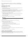
Power Supply Requirements
Adhere to the following requirements in order to operate your Extreme Networks equipment safely:
• Make sure your equipment is placed in an area that accommodates the power consumption and
component heat dissipation specifications.
• Make sure your power supply meets the site power, AC power, or DC power requirements of the
network equipment.
• Make sure DC connections are made by an on-site electrician.
NOTE
For power specifications for Extreme Networks products, see the Extreme Networks website at
http://www.extremenetworks.com.
• When connecting power to installed equipment, avoid connecting through an extension cord or
power strip.
• If your switch includes more than one power supply, connect each power supply to different,
independent power sources. If a power source fails, it will only affect the switch power supply to
which it is connected. If all switch power supplies are connected to a single power source, the entire
switch is vulnerable to a power source failure.
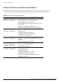
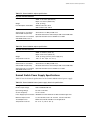
AC Power Cable Requirements
Use an AC power cable appropriate for your country. Check your local electrical codes and regulatory
agencies for power cable requirements. The countries listed in Table 7 and Table 8 have the additional
requirements.
Table 7: General AC power cable requirements
Country
Requirements
USA and Canada
•
The cable set must be UL-approved and CSA-certified. to the rated input power
requirements of the product,
•
The minimum specification for the flexible cable is Type SVT or SJT, 3-conductor.
•
The cable set must have a rated current capacity of at least the amount rated for each
specific product.
Denmark
The supply plug must comply with section 107-2-D1, standard DK2-1a or DK2-5a.
Switzerland
The supply plug must comply with SEV/ASE 1011.
Argentina
The supply plug must comply with Argentinian standards.
NOTE
When using dual power supplies, make sure that each AC power supply attaches to an independent
power source.
50
Extreme Networks Consolidated "e" and "i" Series Hardware Installation Guide
Meeting Power Requirements
Table 8: AC power receptacle requirements
Switch Type
Country
Requirements
Alpine/Summit
North America
15 A service receptacle, NEMA 5-15 for 110/220 VAC power supplies.
Alpine/Summit
United Kingdom
10 A service receptacle, BS 1363 for 110/220 VAC power supplies.
Alpine/Summit
International
10 A service receptacle, CEE 7/7 for 110/220 VAC power supplies.
Alpine/Summit
Australia
10 A service receptacle, AS 3112 for 110/220 VAC power supplies.
Alpine/Summit
Japan
15 A service receptacle, JIS 8303 for 110/220 VAC power supplies.
BlackDiamond
North America
20 A service receptacle, NEMA L5-20 (locking) for BlackDiamond 110
VAC power supplies.
BlackDiamond
North America
20 A service receptacle, NEMA L6-20 (locking) for BlackDiamond 220
VAC power supplies.
BlackDiamond
International
16 A/20 A service receptacle, IEC 60309 for BlackDiamond 220 VAC
power supplies.
BlackDiamond
North America
20 A service receptacle, NEMA 5-20 (non-locking) for BlackDiamond 110
VAC power supplies.
BlackDiamond
North America
20 A service receptacle, NEMA 6-20 (non-locking) for BlackDiamond 220
VAC power supplies.
BlackDiamond
International
16 A service receptacle, CEE 7/7 for BlackDiamond 220 VAC power
supplies.
BlackDiamond
Australia
15 A service receptacle, 036 for BlackDiamond 220 VAC power supplies.
DC Power Requirements
Table 9 lists DC power requirements for Extreme switches.
Table 9: DC power requirements
Switch Type
Country
Requirements
Alpine
International
•
Use 30 A at -40 V DC (or equivalent power between -40 and -70 V DC) for
Alpine DC power supplies.
•
For Alpine DC power and ground cables, use:
— 8 AWG, high strand-count copper wire cable (Alpine 3808)
— 10 AWG, high strand-count copper wire cable (Alpine 3804)
— 14 AWG, high strand-count copper wire cable (Alpine 3802)
BlackDiamond
Summit48si
International
International
•
Use 55 A service for BlackDiamond DC power supplies.
•
For BlackDiamond DC power cables, use 4 AWG, high strand-count copper
wire cable.
•
•
For the Summit48si DC power cable, use the three-wire harness that was
shipped with the Summit48si switch and power supply.
Extreme Networks Consolidated "e" and "i" Series Hardware Installation Guide
51
Site Preparation
Uninterruptable Power Supply Requirements
An uninterruptible power supply (UPS) is a device that sits between a power supply (such as a wall
outlet) and a device (such as a switch) to prevent outages, sags, surges, and bad harmonics from
adversely affecting the performance of the device.
UPS Features
A UPS traditionally can perform the following functions:
• Absorb relatively small power surges.
• Smooth out noisy power sources.
• Continue to provide power to equipment during line sags.
• Provide power for some time after a blackout has occurred.
In addition, some UPS or UPS plus software combinations provide the following functions:
• Automatic shutdown of equipment during long power outages.
• Monitoring and logging of power supply status.
• Display the voltage (current draw) of the equipment.
• Restart equipment after a long power outage.
• Display the voltage currently on the line.
• Provide alarms on certain error conditions.
• Provide short circuit protection.
Selecting a UPS
To determine UPS requirements for your switch, ask these questions:
• What are the amperage requirements?
• What is the longest potential time period that the UPS would be required to supply backup power?
• Where will the UPS be installed?
• What is the maximum transition time that your installation will allow?
NOTE
Extreme Networks recommends that you use a UPS that provides online protection.
Calculating Amperage Requirements
To determine the size of UPS that you need, use the following procedure:
1 To find VA (Volt-Amps), locate the voltage and amperage requirements for each piece of equipment.
These numbers are usually located on a sticker on the back or bottom of your equipment. Then
multiply the numbers together to get VA:
VA = Volts x Amperes
2 Add the VA from each piece of equipment together to find the total VA requirement.
To determine the minimum amperage requirements for your UPS, we recommend that you add 30%
to the total.
52
Extreme Networks Consolidated "e" and "i" Series Hardware Installation Guide
Applicable Industry Standards
UPS Transition Time
Transition time is the time that is necessary for the UPS to transfer from utility power to full-load
battery power. For Extreme Networks products, a transition time of less than 20 milliseconds is required
for optimum performance.
Applicable Industry Standards
For more information, see the following ANSI/TIA/EIA standards:
• ANSI/TIA/EIA-568-A—discusses the six subsystems of a structured cabling system.
• ANSI/TIA/EIA-569-A—discusses design considerations.
• ANSI/TIA/EIA-606—discusses cabling system administration.
• ANSI/TIA/EIA-607—discusses commercial building grounding and bonding requirements.
You can access these standards at http://www.ansi.org/ or http://www.tiaonline.org/.
Extreme Networks Consolidated "e" and "i" Series Hardware Installation Guide
53
Site Preparation
Planning for Optical Budgets
This section provides information about the optical and system budgets for GBICs and mini-GBICs.
Optical Budgets for Mini-GBICs
The total optical system budget for the SX mini-GBIC is 11.5 dB. Extreme Networks recommends that
3 dB of the total budget be reserved for losses induced by cable splices/connectors and operating
margin. While 8.5 dB remains available for cable induced attenuation, the 1000BASE-SX standard
specifies supported distances of 275 meters over 62.5 micron multimode fiber and 550 meters over 50
micron multimode fiber. There is no minimum attenuation or minimum cable length restriction.
The total optical system budget for the LX mini-GBIC is 13.5 dB. Measure cable plant losses with a 1310
nm light source and verify this to be within budget. When calculating the maximum distance attainable
using optical cable with a specified loss per kilometer (for example 0.25 dB/km) Extreme Networks
recommends that 3 dBm of the total budget be reserved for losses induced by cable splices/connectors
and operating margin. Thus, 10.5 dB remains available for cable induced attenuation. There is no
minimum system budget or minimum cable length restriction because the maximum receive power is
the same as the maximum transmit power. There is no minimum attenuation or minimum cable length
restriction.
The ZX mini-GBIC is compatible with and interoperates with long-range GBICs. For more information
about the budget requirements and minimum attenuation requirements of long range GBICs, see
“Long-Range GBIC System Budgets”.
Long-Range GBIC System Budgets
Measure cable plant losses with a 1550 nm light source and verify this to be within budget. When
calculating the maximum distance attainable, using optical cable with a specified loss per kilometer (for
example, 0.25 db/km), Extreme Networks recommends that 3 dB of the total budget be reserved for
losses induced by cable splices, connectors, and operating margin. Figure 14 shows the total optical
system budget between long range GBICs.
NOTE
The fiber loss budget plus all other penalties must not exceed the total optical system budget.
54
Extreme Networks Consolidated "e" and "i" Series Hardware Installation Guide
Planning for Optical Budgets
Figure 14: Total optical system budgets for long range GBICs
ZX GBIC
LX70
19.5 dB
ZX GBIC
Rev. 03
LX70
LX100
ZX GBIC
Rev. 03
LX70
LX70
ZX GBIC
ZX GBIC
Rev. 03
ZX GBIC
Rev. 03
22.0 dB
23.0 dB
LX70
ZX GBIC
20.0 dB
21.5 dB
LX100
23.0 dB
LX100
25.0 dB
23.5 dB
19.0 dB
ZX GBIC
30.0 dB
ZX GBIC
Rev. 03
29.0 dB
18.0 dB
ZX GBIC
21.0 dB
24.5 dB
LX100
27.0 dB
24.0 dB
LX100
XM_041
The ZX mini-GBIC is equivalent to the ZX Rev 03 GBIC.
Table 10 lists the minimum attenuations that are required by each long range GBIC to prevent saturation
of the receiver.
Table 10: Minimum attenuation requirements
Receivers
Transceivers
GBIC Type
LX70
ZX (before
Rev 03)
ZX Rev 03
LX100
LX70
10 dB
10 dB
10 dB
11 dB
ZX (before
Rev 03)
0 dB
0 dB
0 dB
8 dB
ZX Rev 03
8 dB
8 dB
8 dB
9 dB
LX100
11 dB
11 dB
11 dB
12 dB
The ZX mini-GBIC is equivalent to the ZX Rev 03 GBIC.
Extreme Networks Consolidated "e" and "i" Series Hardware Installation Guide
55
Site Preparation
56
Extreme Networks Consolidated "e" and "i" Series Hardware Installation Guide
Part 3
Summit Switch
3
Summit Switch Models
This chapter includes the following information about the Summit family of switches:
• Feature summary
• Physical description
• LED activity
• Port types and configurations
• Power configurations
• Optional features for the Summit switches
The Summit family of switches includes the following models:
• Summit 200 “e” Series on page 60
— Summit 200-24 switch
— Summit 200-24fx switch
— Summit 200-24fx-TAA switch
— Summit 200-48 switch
• Summit 300 “e” Series on page 65
— Summit 300-24 switch
— Summit 300-48 switch
• Summit 400 “e” Series on page 75
— Summit 400-24t and 400-24p switches
— Summit 400-48t switch
• Summit1i on page 88
• Summit5i on page 91
• Summit7i on page 94
• Summit48i on page 98
• Summit48si on page 100
Extreme Networks Consolidated "e" and "i" Series Hardware Installation Guide
59
Summit Switch Models
Summit 200 “e” Series Switches
The Summit 200 “e” series switches include the following switch models:
• Summit 200-24 switch
• Summit 200-24fx switch
• Summit 200-24fx-TAA switch
• Summit 200-48 switch
NOTE
The Summit 200-24fx-TAA switch is compliant with the Trade Agreements Act (TAA).
Summit 200 “e” Series Switch Features
The Summit 200 switches include the Summit 200-24, Summit 200-24fx, Summit 200-24fx-TAA, and
Summit 200-48 switches. These switches are compact enclosures 1U high (1.75 inches or 44.45 mm). The
Summit 200 provides one of the following port configurations:
• 24 autosensing 10BASE-T/100BASE-TX ports using RJ-45 connectors
• 48 autosensing 10BASE-T/100BASE-TX ports using RJ-45 connectors
• 24 full-duplex 100BASEFX ports using LC connectors
The Summit 200 series also provides two uplink ports implemented as combination ports that pair a
copper port using RJ-45 connectors with an optical port using LC connectors. The copper port operates
as an autonegotiating 10/100/1000BASE-T port. The optical port allows Gigabit Ethernet uplink
connections through Extreme small form factor pluggable (SFP) gigabit interface connectors (GBICs),
also known as mini-GBICs. Only one port in the combination pair can be used at one time. These
combination ports are described further in “Summit 200 Automatic Failover” on page 64.
Four types of mini-GBICS are available for the Summit 200 series switches: 1000BASE-SX, 1000BASE-LX,
1000BASE-ZX, or 1000BASE-BX. Mini-GBICs are purchased separately. For more information, contact
your Extreme Networks Sales Representative.
In a Summit stacked configuration using the Summit 200 series switches, the uplink ports provide
interconnection between the stacked switches.
Hardware Features
The Summit 200 series switch is a compact enclosure with the following features:
• One rack unit height (1.75 inches or 44.45 mm)
• 24 or 48 autosensing 10BASE-T/100BASE-TX ports using RJ-45 connectors (Summit 200-24 and
200-48 switches)
• 24 100BASEFX ports using LC connectors (Summit 200-24fx and Summit 200-24fx-TAA switches)
• Two 10/100/1000BASE-T Gigabit Ethernet uplink ports using RJ-45 connectors
• Two optical ports that allow Gigabit Ethernet uplink connections through Extreme mini-GBICs:
— 1000BASE-SX
— 1000BASE-LX
60
Extreme Networks Consolidated "e" and "i" Series Hardware Installation Guide
Summit 200 “e” Series Switches
— 1000BASE-ZX
— 1000BASE-BX
— 1000BASE-T UTP
• Autoranging power supply that automatically adjusts to the supply voltage
Summit 200 Series Switch Physical Description
The 24-port versions of the Summit 200 series switch are the Summit 200-24 switch (Figure 15 and
Figure 16) and the Summit 200-24fx and Summit 200-24fx-TAA switches (Figure 17 and Figure 18). The
48-port version is the Summit 200-48 (Figure 19 and Figure 20).
Figure 15: Summit 200-24 switch front view
10/100 Mbps ports
Mini-GBIC
port status LEDs
1000-baseT ports
Unit stacking Console
ID LED
port
Mini-GBIC ports
LC24001A
Figure 16: Summit 200-24 switch rear view
Power socket
LC24002
Figure 17: Summit 200-24fx and Summit 200-24fx-TAA switch front view
RJ-45
ports
LC duplex fiber connectors
GBIC
ports
Console
port
Unit stacking
ID LED
ES20024fx_002
Extreme Networks Consolidated "e" and "i" Series Hardware Installation Guide
61
Summit Switch Models
Figure 18: Summit 200-24fx and Summit 200-24fx-TAA switch rear view
Power socket
ES20024fx_001
Figure 19: Summit 200-48 switch front view
10/100 Mbps ports
Mini-GBIC ports
Console
port
1000-baseT ports
LC48001
Figure 20: Summit 200-48 switch rear view
Power socket
LC48002
All the ports on the Summit 200 series switch have associated port activity LEDs. In addition, three
LEDs indicate status for the switch, fans, and power supply. The Summit 200-24 switches also have an
LED to indicate the unit ID when the switch is connected in a stacked configuration.
The rear of the Summit 200 series switch provides the AC power connection and air circulation vents.
A system label that lists the serial number and the unique Ethernet MAC address assigned to this
device is on the back of the Summit 200-24 and Summit 200-48 switches and on the side of the Summit
200-24fx and Summit 200-24fx-TAA switches. Use the serial number for fault reporting.
The Summit 200 switch automatically adjusts to the supply voltage. The power supply operates down
to 90 V.
NOTE
The Summit 200 switch certification and safety label is located on the bottom of the switch.
62
Extreme Networks Consolidated "e" and "i" Series Hardware Installation Guide
Summit 200 “e” Series Switches
Summit 200 Switch LEDs
Table 11 describes the LED activity for all three models of the Summit 200 switch.
Table 11: Summit 200 switch LED activity
Unit Status LED (MGMT LED)
Color
Indicates
Green solid
The Summit switch power-on self test (POST) is in progress.
Green blinking
The Summit switch is operating normally.
Amber
The Summit switch has failed its POST or an overheat condition
is detected.
Off
There is no power.
Fan Status LED
Color
Indicates
Green
The fan is operating normally.
Amber blinking The fan system has a failure.
Port Status LEDs
Color
Indicates
Green
Link is present; port is enabled.
Green blinking
Link is present, port is enabled, and there is activity on the port.
Off
Link is not present or the port is disabled.
Fiber Port Status LEDs (Ports 25 and 26 or Ports 49 and 50)
Color
Indicates
Green
Link is present; port is enabled.
Green blinking
Link is present, port is enabled, and there is activity on the port.
Off
Link is not present, port is disabled, non-supported GBIC is
installed on the port, or the RJ-45 uplink port is in use instead of
the fiber port.
Unit Stacking ID Number LED
Color
Indicates
N/A
When several Summit “e” series switches are interconnected
(stacked), each switch is assigned a unique stacking ID number
that is visible in the unit stacking ID number LED. The switch
acting as the stack master is usually assigned the number 1.
However, if there is a saved configuration or if you prefer to
assign a different stacking ID to the stack master, the stack
master can have an ID other than 1.
This LED is available only on the Summit 200-24 and 200-24fx
switches.
Console Port
Use the console port (9-pin, “D” type connector) for connecting a terminal and carrying out local
management.
Extreme Networks Consolidated "e" and "i" Series Hardware Installation Guide
63
Summit Switch Models
Port Connections
A Summit 200-24 or 200-48 switch has either 24 or 48 10BASE-T/100BASE-TX ports using RJ-45
connectors for communicating with end stations and other devices over 10/100Mbps Ethernet.
A Summit 200-24fx/200-24fx-TAA switch has 24 100BASE-FX ports for communicating with end
stations or other devices over 100Mbps Ethernet.
The switch also has four Gigabit Ethernet uplink ports, of which only two can be used at any one time.
These combination ports are labeled 25 and 26 on the front panel of the Summit 200-24 or 200-24fx and
labeled 49 and 50 on the front panel of the Summit 200-48. Two of the ports are 10/100/1000BASE-T
ports using RJ-45 connectors. The other two ports are unpopulated receptacles for mini-GBICs (SFPs),
using optical fibers with LC connectors. All models of the Summit 200 support the use of 1000BASE-SX,
1000BASE-LX, 1000BASE-ZX, or 1000BASE-BX mini-GBICs.
The uplink ports can be used as the interconnect ports in a Summit switch stacked configuration. For
more information about configuring and operating a Summit switch stack, see the ExtremeWare Software
User Guide.
NOTE
Only mini-GBICs that have been certified by Extreme Networks (available from Extreme Networks)
should be inserted into the mini-GBIC receptacles on the Summit 200 series switch.
Summit 200 Automatic Failover
The Summit 200 switch supports an automatic failover from an active fiber port to a copper backup or
from an active copper port to a fiber port. If one of the uplink connections fails, the Summit 200 uplink
connection automatically fails over to the second connection. On the Summit 200-24 and 200-48
switches, the preferred medium is fiber and cannot be configured. On the Summit 200-24fx and Summit
200-24fx-TAA switches, the switch determines whether the port uses the copper or fiber connection
based on the order in which the connectors are inserted into the switch.
On the Summit 200-24, 200-24fx, 200-24fx-TAA switches, ports 25 and 26 are the Gigabit Ethernet ports
that have the redundant PHY interfaces. On the Summit 200-48 switch, ports 49 and 50 have the
redundant PHY interfaces. Each port has one mini-GBIC and one copper 1000BASE-T connection.
To set up a redundant link on one of the uplink ports, connect the active fiber and 1000BASE-T links to
both the RJ-45 and mini-GBIC interfaces of that port.
Uplink Redundancy on the Summit 200-24 Switch and Summit 200-48 Switch
On the Summit 200-24 and 200-48 switches, Gigabit Ethernet uplink redundancy follows these rules:
• Only one interface on each port can be active at a time. For example, on port 25 of the Summit
200-24 switch, with both the mini-GBIC and 1000BASE-T interfaces connected, only one interface can
be activated. The other is inactive. If both interfaces are connected, the switch defaults to the fiber
interface (mini-GBIC) and deactivates the 1000BASE-T interface.
• If only one interface is connected, the switch activates the connected interface.
• To set up a redundant link on an uplink port, connect the active fiber and 1000BASE-T links to both
the RJ-45 and mini-GBIC interfaces of the port. The switch defaults to the fiber link. If the fiber link
fails during operation, the switch automatically activates the redundant 1000BASE-T link.
64
Extreme Networks Consolidated "e" and "i" Series Hardware Installation Guide
Summit 300 “e” Series Switches
NOTE
When configuring the Summit 200-48 switch, all ports specified as mirrored ports and mirroring port, or
ACL ingress ports and egress port, must belong to the same port group. Port group 1 consists of ports
1 through 24 and port 49; port group 2 consists of ports 25 through 48 and port 50.
Uplink Redundancy on the Summit 200-24fx and Summit 200-24fx-TAA Switch
Gigabit Ethernet uplink redundancy on the Summit 200-24fx and Summit 200-24fx-TAA switch follows
these rules:
• Only one interface on each port can be active at a time. For example, on port 25, with both the
mini-GBIC and 1000BASE-T interfaces connected, only one interface can be activated. The other is
inactive.
• If only one interface is connected, the switch activates the connected interface.
• The switch determines whether the port uses the fiber or copper connection based on the order in
which the connectors are inserted into the switch. When the switch senses that a mini-GBIC and a
copper connector are inserted, the switch enables the uplink redundancy feature. For example, if you
first insert mini-GBICs into ports 25 and 26, and then connect copper ports 25 and 26, the switch
assigns the copper ports as redundant ports.
• To set up a redundant link on a port, connect the active fiber and 1000BASE-T links to both the RJ-45
and mini-GBIC interfaces of port 49. The switch defaults to the fiber link. If the fiber link fails during
operation, the switch automatically activates the redundant 1000BASE-T link.
Hardware determines when a link is lost and swaps the primary and redundant ports to maintain
stability. After a failover occurs, the switch keeps or sticks with the current port assignment until there
is another failure or a user changes the assignment using the CLI. To change the uplink failover
assignment, use the following command:
configure ports <nnn> preferred-medium {copper} | {fiber} |[force]
The default preferred-medium is fiber. If you use the force option, it disables automatic failover. If you
force the preferred-medium to fiber and the fiber link goes away, the copper link is not used, even if
available.
Full-Duplex Support
The Summit 200 switches provide full-duplex support for all ports. Full-duplex allows frames to be
transmitted and received simultaneously and, in effect, doubles the bandwidth available on a link. All
10/100 Mbps ports on the Summit 200 switch autonegotiate for half- or full-duplex operation.
Summit 300 “e” Series Switches
The Summit 300 “e” series switches include the following switch models:
• Summit 300-24 switch
• Summit 300-48 switch
Extreme Networks Consolidated "e" and "i" Series Hardware Installation Guide
65
Summit Switch Models
Summit 300 Features
The Summit 300 series switch supports wireless and Power over Ethernet (PoE) networks. These
switches provide 24 or 48 autosensing 10BASE-T/100BASE-TX ports using RJ-45 connectors.
The Summit 300 series switches also provide either two or four uplink ports implemented as
combination ports that pair a copper port using RJ-45 connectors with an optical port using LC
connectors. The copper port operates as an autonegotiating 10/100/1000BASE-T port. The optical port
allows Gigabit Ethernet uplink connections through Extreme small form factor pluggable (SFP) gigabit
interface connectors (GBICs), also known as mini-GBICs. Only one port in the combination pair can be
used at one time. These combination ports are described further in “Summit 300 Automatic Failover” on
page 74.
Four types of mini-GBICS are available for the Summit 300 series switches: 1000BASE-SX, 1000BASE-LX,
1000BASE-ZX, and 1000BASE-BX. Mini-GBICs are purchased separately. For more information, contact
your Extreme Networks Sales Representative.
The Summit 300 series switches support Power over Ethernet (PoE) as defined by the IEEE 802.3af
specification. PoE is an effective method of supplying 48 VDC power to certain types of powered
devices by way of Category 5 or Category 3 twisted pair Ethernet cables. Supported devices include the
Altitude 300 wireless port, IP telephones, laptop computers, web cameras, or other devices. With PoE, a
single Ethernet cable supplies power and the data connection, thereby saving time and expense
associated with separate power cabling and supply.
Hardware Features
The Summit 300 switch has the following features:
• Gigabit Ethernet uplinks, fiber/UTP redundant
— 2 uplink ports on the Summit 300-24
— 4 uplink ports on the Summit 300-48
• 10/100 Ethernet ports
— 24 ports on the Summit 300-24
— 48 ports on the Summit 300-48
• Serial management port
• Autoranging power supply that automatically adjusts to the AC supply voltage
• Optional redundant power supplies
— Rack-mountable External Power Supply 45019 (EPS-LD) for the Summit 300-24
— Hot-swappable internal redundant power supply for the Summit 300-48
• Modular expansion slot on the Summit 300-48 that supports various port configurations
Summit 300-24 Switch
The Summit 300-24 is 1U high and provides 24 autosensing 10BASE-T/100BASE-TX ports using RJ-45
connectors. The Summit 300-24 switch also provides two combination uplink ports implemented as
either 10/100/1000BASE-T ports using RJ-45 connectors or optical ports using mini-GBICs.
The Summit 300-24 switch can be interconnected with other Summit 300-24 switches or Summit 200
series switches to form a stacked configuration that is managed as a single switch entity. In a Summit
stacked configuration, the uplink ports provide interconnection between the stacked switches.
66
Extreme Networks Consolidated "e" and "i" Series Hardware Installation Guide
Summit 300 “e” Series Switches
Figure 21 shows the front of the Summit 300-24 switch.
Figure 21: Summit 300-24 switch front view
10/100 Mbps ports
Management
LED
Fan LED
PSU LEDs
Mini-GBIC
port status LEDs
10/100/1000-baseT ports
Console
port
Mini-GBIC/
1000-baseX ports
RVN24001A
The front panel of the Summit 300-24 switch includes LEDs, a console port, fixed 10/100 Mbps ports,
and high-speed uplink ports implemented as either a 10/100/1000 Mbps copper port or an installed
1000-BASEx mini-GBIC.
Figure 22 shows the rear of the Summit 300-24 switch.
Figure 22: Summit 300-24 switch rear view
Slot for key
Power socket
Redundant
power cable
RVN24002
The rear panel of the Summit 300-24 switch provides air circulation vents, an AC power socket, a
system label, and a redundant power connector. The AC power connector provides power to the switch
when a power cable is connected. The system label provides the manufacturing serial number the
unique Ethernet MAC address that is assigned to this device. Use the serial number for fault reporting.
The redundant power connector allows you to connect a redundant power supply to provide redundant
support for the Power over Ethernet (PoE) functions of the switch. For more information about the
redundant power supply, see “Redundant Power Supply” on page 70. For connector pinouts, see
“Pinouts for Summit 300-24 switch redundant power connector” on page 337
Summit 300-24 Switch LEDs
The LED activity on the Summit 300-24 is described in Table 12.
Extreme Networks Consolidated "e" and "i" Series Hardware Installation Guide
67
Summit Switch Models
Table 12: Summit 300-24 switch LED activity
Unit Status LED (MGMT LED)
Color
Indicates
Green, solid
The Summit switch POST is in progress.
Green, blinking The Summit switch is operating normally.
Amber,
blinking
The Summit switch has failed its POST or an overheat condition
is detected.
Off
There is no power.
Color
Indicates
Green, solid
All fans are operating normally.
Amber,
blinking
One or more fans has failed. The switch continues to operate
unless over-heating occurs.
Off
The Summit switch has no power.
Fan LED
Power Supply LEDs
PSU-I
PSU-E
Color
Indicates
Green, solid
The internal power supply is operating normally.
Amber,
blinking
The internal power supply has failed, or the AC connector is not
plugged-in. If the power supply has failed, replace the internal
power supply as soon as possible.
Off
The internal power supply has no power.
Color
Indicates
Green, solid
The external power supply is operating normally.
Amber,
blinking
The external power supply has failed, or the AC connector is not
plugged-in.
Off
The external power supply is not connected.
Port Status LEDs (Ports 1-24)
68
Color
Indicates
Green, solid
Link is present and port is enabled; non-powered device.
Green, fast
blinking
Port is enabled; link is up, device non-powered and activity on the
port.
Amber, solid
Link is present and port is enabled; device powered.
Amber, slow
blinking
Link is down or port is disabled; device powered.
Amber, fast
blinking
Port is enabled; link is up, device powered and activity on the
port.
Alternating
amber/green
There is a power fault.
Off
The link is down or the port is disabled; non-powered device.
Extreme Networks Consolidated "e" and "i" Series Hardware Installation Guide
Summit 300 “e” Series Switches
Table 12: Summit 300-24 switch LED activity (Continued)
Fiber Port Status LEDs (Ports 25—26)
Color
Indicates
Green
Link is present; port is enabled.
Green blinking
Link is present, port is enabled, and there is activity on the port.
Off
Link is not present, port is disabled, or non-supported GBIC is
installed on the port. The RJ-45 port is being used for the uplink.
Unit Stacking ID Number LED
Color
Indicates
N/A
When several Summit “e” series switches are interconnected
(stacked), each switch is assigned a unique stacking ID number
that is visible in the unit stacking ID number LED. The switch
acting as the stack master is usually assigned the number 1.
However, if there is a saved configuration or if you prefer to
assign a different stacking ID to the stack master, the stack
master can have an ID other than 1.
This LED is available only on the Summit 300-24
Console Port
Use the console port (9-pin, “D” type connector) for connecting a terminal and carrying out local
management.
Port Connections
The Summit 300-24 switch uses a combination of 10BASE-T/100BASE-TX ports using RJ-45 connectors
and small form factor pluggable (SFP) Gigabit interface connectors (GBICs), also known as mini-GBICs.
Ports 1 through 24 are 10/100BASE-T ports with RJ-45 connectors.
Ports 25 and 26 are Gigabit Ethernet ports that have redundant PHY interfaces for uplink redundancy.
The dual-media support consists of one mini-GBIC and one 1000BASE-T connection for each port. Only
one media type (fiber or copper) can be active at the same time.
The switch determines whether the port is the primary or redundant port based upon the order in
which the cables are inserted into the switch. When the switch senses that cables are in both the fiber
and corresponding copper port, the switch enables the uplink redundancy feature. For further
information, see “Summit 300 Automatic Failover” on page 74.
Ports 25 and 26 can be used as the interconnect ports in a Summit switch stacked configuration. For
more information about configuring and operating a Summit switch stack, see the ExtremeWare User
Guide.
Full-Duplex. The Summit 300-24 switch provides full-duplex support for all ports. Full-duplex allows
frames to be transmitted and received simultaneously and, in effect, doubles the bandwidth available on
a link. All 10/100 Mbps ports on the Summit 300-24 switch autonegotiate for half- or full-duplex
operation.
Extreme Networks Consolidated "e" and "i" Series Hardware Installation Guide
69
Summit Switch Models
Redundant Power Supply
Summit 300-24 switch software is responsible for managing overall power consumption to ensure that it
does not attempt to deliver more power than is available. The Summit 300-24 has sufficient power
budget to provide full 15.4 watts power on all 24 ports simultaneously.
The Extreme Networks External Power Supply 45019 (EPS-LD) is an optional external power supply
that provides redundant power for the Summit 300-24 switch. For instructions to install and connect the
EPS-LD, see “Installing or Removing an External Power Supply 45019 (EPS-LD)” on page 118.
To determine the wattage of installed power supplies when the power supplies are in 1-to-1 redundant
mode, use the show inline-power command. When the power supplies are in PoE mode, most of the
power is dissipated externally to the switch by way of the inside attached powered devices.
Summit 300-48 Switch
The Summit 300-48 is 2U high and provides 48 autosensing10BASE-T/100BASE-TX ports using RJ-45
connectors. The Summit 300-48 also provides four combination uplink ports implemented as either
10/100/1000BASE-T ports using RJ-45 connectors or optical ports using mini-GBICs. The optical ports
are also combination uplink ports. For further information, see “Summit 300 Automatic Failover” on
page 74.
The Summit 300-48 requires a minimum software level of ExtremeWare 6.2a.1.2.
The Summit 300-48 is shown in Figure 23 and Figure 24.
Figure 23: Summit 300-48 switch front view
10/100/1000 Mbps ports
Expansion module slot
Mini-GBIC ports
Console port
10/100 Mbps ports with PoE
LB48001
The front panel of the Summit 300-48 switch includes LEDs, fixed 10BASE-T/100BASE-TX ports,
unpopulated ports for installing mini-GBICs, and a console port.
70
Extreme Networks Consolidated "e" and "i" Series Hardware Installation Guide
Summit 300 “e” Series Switches
Figure 24: Summit 300-48 switch rear view
Power switch
PSU-B
PSU-A
Power socket
LB48002B
The rear panel of the Summit 300-48 switch provides the AC power connector and power switch for
each installed power supply. Do not turn on power to the switch until instructed in the installation
procedures. The Summit 300-48 switch automatically adjusts to the supply voltage. The power supply
operates down to 90 V.
LEDs on the rear panel indicate voltage out and voltage in conditions, as well as over-temperature
conditions.
NOTE
The Summit 300-48 switch certification and safety label, and the serial number and MAC address labels
are located on the bottom of the switch.
Summit 300-48 Switch LEDs
The LED activity for the Summit 300-48 is shown in Table 13.
Table 13: Summit 300-48 switch LED activity
Unit Status LED (MGMT LED)
Color
Indicates
Solid Green
The Summit switch POST is in progress
Blinking Green The Summit switch is operating normally.
Solid Amber
The Summit has failed its POST.
Off
No power.
Power Supply Status LEDs (per power supply)
Color
Indicates
Solid Green
The power supply is operating normally.
Solid Amber
There is a fault.
Off
There is no power.
Fan Unit Status LEDs
Color
Indicates
Solid Green
The fan is operating normally.
Solid Amber
There is a fault.
Off
There is no power.
Extreme Networks Consolidated "e" and "i" Series Hardware Installation Guide
71
Summit Switch Models
Table 13: Summit 300-48 switch LED activity (Continued)
Power Supply Status LEDs
LED
Color
Indicates
OUT
Solid Green
The output voltages are enabled and within specification.
Off
There is a fault on at least one output voltage or voltages are out
of specification.
Solid Amber
The fan failed or there is an over temperature condition.
Off
The fan is operating normally and operating temperature is within
limit.
Solid Green
The input voltage is within specification and the input section is
working.
Off
The input voltage is out of range or there is a fault in the input
section.
TEMP
IN
10/100 Mbps Port Status LEDs
Color
Indicates
Green, solid
Link is present and port is enabled; non-powered device.
Green, fast blinking
Port is enabled; link is up, device non-powered and activity on the
port.
Amber, solid
Link is present and port is enabled; device powered.
Amber, slow blinking
Link is down or port is disabled; device powered.
Amber, fast blinking
Port is enabled; link is up, device powered and activity on the
port.
Alternating amber/green
There is a power fault.
Off
The link is down or the port is disabled; non-powered device.
10/100/1000 Mbps Port Status LEDs
Color
Indicates
Green solid
Link is present; port is enabled; full-duplex operation.
Green blinking
Link is present; there is activity.
Amber blinking
Reserved.
Off
Link is not present or the port is disabled.
Fiber Port Status LEDs
Color
Indicates
Solid Green
Link is present; port is enabled; full-duplex operation.
Blinking Green
Link is present; there is activity.
Off
Link is not present; port is disabled; mini-GBIC is not installed.
Console Port
Use the console port (9-pin, “D” type connector) for connecting a terminal and carrying out local
management.
Port Connections
The Summit 300-48 switch uses a combination of 10BASE-T/100BASE-TX ports using RJ-45 connectors
and small form factor pluggable (SFP) Gigabit interface connectors (GBICs), also known as mini-GBICs.
72
Extreme Networks Consolidated "e" and "i" Series Hardware Installation Guide
Summit 300 “e” Series Switches
Ports 1 through 48 are 10/100 ports with RJ45 connectors.
Full-Duplex. The Summit 300-48 switch provides full-duplex support for all ports. Full-duplex allows
frames to be transmitted and received simultaneously and, in effect, doubles the bandwidth available on
a link. All 10/100 Mbps ports on the Summit 300-48 switch autonegotiate for half- or full-duplex
operation.
Load Sharing Power Supplies
The PoE subsystem in the Summit 300-48 supports dual power supplies for either redundant or
load-sharing modes. Redundant mode is the default and provides hitless PoE should one of the two
power supplies fail, be removed, or powered off. Load-sharing mode allows both power supplies to
provide power to the PoE system, providing greater PoE power capacity. For load-sharing operation,
the amount of power provided to the PoE system is the sum of the power supplied by the power
supplies.
NOTE
With load-sharing, all PoE devices may experience a power hit if a power supply fails.
The Summit 300-48 switch is shipped with either one or two installed 600 W AC internal power supply
units (PSUs). For technical specifications of the power supplies, see “Summit 300-48 internal power
supply electrical specifications” on page 323.
To determine the wattage of the installed PSUs when the PSUs are in redundant mode, use the show
inline-power command. If System maximum internal inline-power field indicates 480 W, that
means that 600 W PSUs are installed.
Power Supply LEDs
The Summit 300-48 power supply has three LEDs that are visible from the rear of the Summit 300-48
when the supply is installed, as shown in Figure 25. The IN LED indicates the condition of the input
power (AC power source). When the input power is satisfactory, the IN LED is green, otherwise it is off.
The TEMP LED indicates the condition of the cooling fan or operating temperature. When the operating
temperature and fan cooling is satisfactory the TEMP LED is off, otherwise it is amber. The OUT LED
indicates the condition of the output DC power supplied by the power supply to the switch. When the
output power is satisfactory the OUT LED is green, otherwise it is off.
Extreme Networks Consolidated "e" and "i" Series Hardware Installation Guide
73
Summit Switch Models
Figure 25: Power supply LEDs
LB48023
Table 14: Summit 300-48 power supply LED activity
Condition
IN LED
Indication
TEMP LED
Indication
OUT LED
Indication
Normal
Green
Off
Green
Supply Inhibited or overloaded
Green
Off
Off
Input AC Low or Missing
Off
Off
Off
Fan Failure or Over Temperature
Green
Amber
Off
Summit 300 Automatic Failover
The Summit 300 switches provide dual-media support on Gigabit Ethernet ports. On the Summit
300-24, ports 24 and 25 are Gigabit Ethernet ports that have redundant PHY interfaces, one mini-GBIC
and one 1000BASE-T connection for each port. On the Summit 300-48, ports 1:49 through 1:52 are
dual-mode redundant ports. Only one media type (fiber or copper) can be active at the same time on
those ports.
The two fiber ports and the last two of the 10/100/1000BASE-T ports on the Summit 300-24 and the
four fiber ports and the last four of the 10/100/1000BASE-T ports on the Summit 300-48 are designed as
combination ports for uplink redundancy. When sharing ports, only the fiber medium or only the
copper medium can be active at the same time. If copper medium 1 goes down while transmitting
packets, fiber medium 1X activates and becomes the primary link.
The switch determines whether the port uses the primary or redundant media based on the order in
which the connectors are inserted into the switch. When the switch senses that a mini-GBIC and a
copper connector are inserted, the switch enables the uplink redundancy feature. For example, if you
first insert mini-GBICs into ports 1:49 and 1:51 on the Summit 300-48, and then connect copper ports 1:1
and 1:3, the switch assigns ports 1:1 and 1:3 as redundant ports. On the Summit 300-24, if you insert a
mini-GBIC into port 24 and then an Ethernet cable connector into port 1, fiber becomes the primary
uplink port and port 1 becomes the redundant port.
Hardware determines when a link is lost and swaps the primary and redundant ports to maintain
stability. After a failover occurs, the switch keeps or sticks with the current port assignment until there
74
Extreme Networks Consolidated "e" and "i" Series Hardware Installation Guide
Summit 400 “e” Series Switches
is another failure or a user changes the assignment using the CLI. To change the uplink failover
assignment, use the following command:
configure ports <nnn> preferred-medium {copper} | {fiber} |[force]
The default preferred-medium is fiber. If you use the force option, it disables automatic failover. If you
force the preferred-medium to fiber and the fiber link goes away, the copper link is not used, even if
available.
Summit 400 “e” Series Switches
The Summit 400 “e” series switches include the following switch models:
• Summit 400-24t switch
• Summit 400-24p switch
• Summit 400-48t switch
Summit 400-24 Switches
The Summit 400-24t or 400-24p switch is a compact enclosure (see Figure 26) one rack unit high (1.73
inches or 44.0 mm) that provides 24 autosensing 10/100/1000BASE-T ports using RJ-45 connectors. On
the Summit 400-24p switch, these ports support Power over Ethernet operation as defined by the IEEE
802.3af specification. The Summit 400-24 switch also has four fiber ports that allow Gigabit Ethernet
uplink connections through Extreme 1000BASE-SX, 1000BASE-LX, 1000BASE-ZX, or 1000BASE-BX SFP
mini-GBICs using LC connectors. The four fiber ports and the last four of the 10/100/1000BASE-T ports
are designed as shared, or combination, ports for uplink redundancy. When sharing ports, only the fiber
port or only the copper port can be active at the same time. For more information about cabling and
configuring this feature, see “Uplink Redundancy” on page 80.
The back panel of the Summit 400-24 switch provides two high-performance dedicated stacking
connectors for interconnecting Summit 400-series switches in a stacked configuration.
Hardware Features
The Summit 400-24 switch has the following hardware features:
• 24 10/100/1000BASE-T ports
• 4 fiber SFP (mini-GBIC 1000BASE-SX, 1000BASE-LX, 1000BASE-ZX, and 1000BASE-BX)
The fiber ports share PHY with the last four copper ports.
• 1 console port, serial
• 2 dedicated stacking ports (10 Gigabit)
• Support for redundant power support using the optional EPS 160 External Power Supply (Summit
400-24t) or the EPS-LD External Power Supply (Summit 400-24p)
• Redundant uplink support
Extreme Networks Consolidated "e" and "i" Series Hardware Installation Guide
75
Summit Switch Models
Summit 400-24 Physical Description
Figure 26 shows the front of the Summit 400-24t switch. Figure 27 shows the front of the Summit
400-24p switch.
Figure 26: Summit 400-24t switch front view
Stack Number
LED
Solid ON - Link
Blinking - Activity
MGMT
STACK NO.
FAN
PSU-I
PSU-E
1
10/100/1000 Mbps ports
2
3
4
5
6
7
8
9
10
11
12
13
14
15
16
17
18
Mini-GBIC ports
19
20
21
22
23
Console
port
24
Stack
Port
St-1
21X
22X
23X
24X
St-2
Shared Ports
Shared ports
ES4K032
Figure 27: Summit 400-24p switch front view
Stack Number
LED
Solid ON - Link
Blinking - Activity
MGMT
FAN
PSU-I
PSU-E
STACK NO.
1
10/100/1000 Mbps ports
2
3
4
5
6
7
8
9
10
11
12
13
14
15
16
17
18
19
20
Mini-GBIC ports
21
22
Stack
Port
St-1
23
24
PORTS 1-24
POWERED (AMBER) ON-LINK
FLASHING - ACTIVITY
SLOW BLINK - NO LINX/DISABLED
ALTERNATE AMBER/GREEN-PWR FAULT
21X
22X
Console
port
NO POWER (GREEN) ON-LINK
FLASHING - ACTIVITY
OFF - NO LINK/DISABLED
23X
24X
St-2
Shared Ports
Shared ports
ES4K033
The front panel includes LEDs, fixed 10/100/1000BASE-T ports, unpopulated ports for installing
mini-GBICs, and a console port.
Figure 28 shows the rear view of the Summit 400-24t switch. Figure 29 shows the rear view of the
Summit 400-24p switch.
Figure 28: Summit 400-24t switch rear view
External power
supply connection
10 Gigabit
stacking ports
Power socket
ES4K035A
76
Extreme Networks Consolidated "e" and "i" Series Hardware Installation Guide
Summit 400 “e” Series Switches
Figure 29: Summit 400-24p switch rear view
External power
supply connection
10 Gigabit
stacking ports
Power socket
ES4K034A
The rear panel includes:
• Two high-performance stacking ports.
These ports are used to interconnect the switches in a Summit switch stacked configuration. They
require a stacking cable that is available from Extreme Networks.
• Vents for the internal power supply fan.
• Connector for an optional external power supply.
• AC power socket.
The Summit 400-24 switch automatically adjusts to the supply voltage. The power supply operates
from 100 VAC to 240 VAC.
NOTE
The Summit 400-24 switch certification, safety label, and serial number are located on the bottom of the
switch.
Summit 400-24 Switch LEDs
The front panel has five types of LEDs:
• Management
The MGMT LED indicates the status of the switch.
• Fan
The FAN LED indicates the status of the cooling fans.
• Power
The Summit 400-24 switch comes with an internal power supply and can be connected to the
Extreme External Power Supply tray. The status of the internal power supply is indicated by the
PSU-I LED. The status of the external power supply is indicated by the PSU-E LED.
• 10/100/1000BASE-T port status
Each of the 24 copper 10/100/1000BASE-T ports on the Summit 400-24t switch has an associated
LED located above the port.
• Fiber port status
Each of the four optical fiber ports has an associated LED located to the left of the port.
Each stacking port on the back of the switch also has an associated LED.
Extreme Networks Consolidated "e" and "i" Series Hardware Installation Guide
77
Summit Switch Models
Table 15 describes the activity of the LEDs on the Summit 400-24 switch.
Table 15: Summit 400-24 switch LED activity
Unit Status LED (MGMT LED)
Color
Indicates
Green, slow
blinking
The Summit switch is operating normally.
Green, fast
blinking
The Summit switch POST is in progress.
Green, solid
POST passed; ExtremeWare is booting.
Amber, blinking
The Summit switch has failed its POST or an overheat condition is
detected.
Off
The Summit switch has no power.
Fan Status LED
Color
Indicates
Green solid
All fans are operating normally.
Amber blinking
One or more fans has failed. The switch continues to operate unless
over-heating occurs.
Off
The Summit switch has no power.
Power Supply LEDs
PSU-I
Color
Indicates
Green, solid
The internal power supply is operating normally.
Amber, blinking
The internal power supply has failed. Replace the internal power supply
as soon as possible.
Off
The internal power supply has no power.
PSU-E
Color
Indicates
Green, solid
The external power supply is operating normally.
Off
The external power supply is not connected.
Port Status LEDs (Ports 1–24)—Summit 400-24t switch
78
Color
Indicates
Green, solid
The link is present; port is enabled.
Green, blinking
The link is present and the port is transmitting or receiving packets.
Off
The link is not present.
Extreme Networks Consolidated "e" and "i" Series Hardware Installation Guide
Summit 400 “e” Series Switches
Table 15: Summit 400-24 switch LED activity
Port Status LEDs (Ports 1–24)—Summit 400-24p switch
Color
Indicates
Green, solid
Link is present and port is enabled; non-powered device.
Green, fast
blinking
Port is enabled; link is up, device non-powered and activity on the port.
Amber, solid
Link is present and port is enabled; device powered.
Amber, slow
blinking
Link is down or port is disabled; device powered.
Amber, fast
blinking
Port is enabled; link is up, device powered and activity on the port.
Alternating
amber/green
There is a power fault.
Off
The link is down or the port is disabled; non-powered device.
Fiber LEDs (Ports 21X–24X)
Color
Indicates
Green, solid
Fiber link is selected; mini-GBIC is present and being used for the
Gigabit Ethernet uplink.
Green, blinking
The link is present and the port is transmitting or receiving packets.
Off
1000BASE-T link is selected; the switch is using the RJ-45 port for the
Gigabit Ethernet uplink.
Stack Number LED
Color
Indicates
N/A
When several Summit “e” series switches are interconnected (stacked),
each switch is assigned a unique stacking ID number that is visible in
the unit stacking ID number LED. The switch acting as the stack master
is usually assigned the number 1. However, if there is a saved
configuration or if you prefer to assign a different stacking ID to the
stack master, the stack master can have an ID other than 1.
This LED is available only on the Summit 400-24.
Stacking Port Status LED
Color
Indicates
Green, solid
The link is present; port is enabled.
Green, blinking
The link is present and the port is transmitting or receiving packets.
Off
The link is not present.
Port Connections
The Summit 400-24 switch has 24 copper 10/100/1000BASE-T ports using RJ-45 connectors for
communicating with end stations and other devices over 10/100/1000 Mbps Ethernet.
The switch also has four fiber ports that allow Gigabit Ethernet uplink connections through Extreme
1000BASE-SX, 1000BASE-LX, 1000BASE-SX, or 1000BASE-BX SFP mini-GBICs using LC connectors.
Two stacking connectors on the back of the switch allow interconnection of the switch in a Summit
switch stacked configuration. For information about using these ports, see “Installing a Summit Stacked
Configuration” on page 112. For information about configuring and operating a Summit switch stack,
see the ExtremeWare Software User Guide.
Extreme Networks Consolidated "e" and "i" Series Hardware Installation Guide
79
Summit Switch Models
The switch provides full-duplex support for all ports. Full-duplex allows frames to be transmitted and
received simultaneously and, in effect, doubles the bandwidth available on a link. All 10/100/1000
Mbps ports on the Summit 400-24 switch autonegotiate for half- or full-duplex operation.
Uplink Redundancy
The four fiber ports and the last four of the 10/100/1000BASE-T ports are designed as combination
ports for uplink redundancy. When a pair of ports is shared, only the fiber port or only the copper port
can be active at the same time. For example, if copper port 21 goes down while transmitting packets,
fiber port 21X activates and becomes the primary link. See Figure 30 for a diagram of these combination
ports.
The switch determines whether the port is the primary or redundant port based on the order in which
the cables are inserted into the switch. When the switch senses that cables are in both the fiber and
corresponding copper port, the switch enables the uplink redundancy feature. For example, if you insert
mini-GBICs into ports 21X and 23X first, and then connect copper ports 21 and 23, the switch assigns
ports 21 and 23 as redundant ports.
Figure 30: Shared ports on the Summit 400-24 switch
21
22
23
24
21X
22X
23X
24X
Shared Ports
ES4K036
You can override the configuration and behavior of these ports through the CLI. Using the CLI, you can
set a preference for either fiber or copper. You can also turn off port redundancy using the force option.
If a combination port fails to link, determine whether the force option is in effect. For more information
about using the CLI to set redundancy priority, see the ExtremeWare Software Users Guide.
The Summit 400-24 switch Gigabit Ethernet port failover from the fiber link to the copper link takes
4 to 5 seconds. The Summit 400-24 switch Gigabit Ethernet port failover from the copper link to the fiber
link takes 2 to 3 seconds.
Summit 400-48t switch
The Summit 400-48t switch is a compact enclosure (see Figure 31) one rack unit in height (1.73 inches or
44.0 mm) that provides 48 autosensing 10/100/1000BASE-T ports using RJ-45 connectors. The switch
also has four fiber ports that allow Gigabit Ethernet uplink connections through Extreme 1000BASE-SX,
1000BASE-LX, 1000BASE-ZX, or 1000BASE-BX SFP mini-GBICs using LC connectors. The four fiber
ports and the first four of the 10/100/1000BASE-T ports are designed as shared, or combination ports for
uplink redundancy. When sharing ports, only the fiber port or only the copper port can be active at the
80
Extreme Networks Consolidated "e" and "i" Series Hardware Installation Guide
Summit 400 “e” Series Switches
same time. For more information about cabling and configuring this feature, see “Uplink Redundancy”
on page 85.
The back panel of the Summit 400-48t switch provides an option slot for two modular 10-gigabit uplink
ports. In addition, two high-performance dedicated stacking connectors allow you to interconnect
Summit 400-series switches in a stacked configuration.
Hardware Features
The Summit 400-48t switch has the following hardware features:
• 48 copper ports (10/100/1000BASE-T)
• 4 fiber SFP ports (mini-GBIC 1000BASE-SX, 1000BASE-LX, 1000BASE-ZX, and 1000BASE-BX)
The fiber ports share PHY with the first four copper ports.
• 1 copper management port 10/100/1000BASE-T
• 1 console port, serial
• 2 (optional) modular 10 Gigabit uplink ports
• 2 dedicated stacking ports (10 Gigabit)
• Support for redundant power support using the optional EPS 160 External Power Supply
• Redundant uplink support
Summit 400-48t Physical Description
Figure 31 shows the front of the Summit 400-48t switch.
Figure 31: Summit 400-48t switch front view
Mini-GBIC ports
10/100/1000
10/100 Mbps ports
Console
port
ES4K001
The front panel includes:
• LEDs to indicate switch and port operating status (see “Summit 400-48t Switch LEDs” on page 82).
• 10/100/1000BASE-T ports (see “Port Connections” on page 84).
• Console Port—Use the console port (9-pin, “D” type connector) to attach a terminal and access the
CLI through a serial connection. Use the console port to carry out local management.
Figure 32 shows the rear panel of the Summit 400-48t switch.
Extreme Networks Consolidated "e" and "i" Series Hardware Installation Guide
81
Summit Switch Models
Figure 32: Summit 400-48t switch rear view
External power
supply connection
Compact flash
Mgmt port
10 Gigabit
uplink option
10 Gigabit stacking ports
(reserved for future)
Power socket
ES4K018B
The rear panel includes:
• An option slot for the dual 10 Gigabit uplinks
• The management port (see “Management Port” on page 84)
• A compact flash slot
This slot is currently not supported but is reserved for future use.
• Two high-performance dedicated stacking ports
These ports are used to interconnect the switches in a Summit switch stacked configuration. They
require the UniStack Stacking Cable, available from Extreme Networks.
• Vents for the internal power supply fan.
• The connector for the optional Extreme External Power Supply System.
• AC Power Socket
The Summit 400-48t switch automatically adjusts to the supply voltage. The power supply operates
from 100 VAC to 240 VAC.
NOTE
The Summit 400-48t switch certification, safety label, and serial number are located on the bottom of
the switch.
Summit 400-48t Switch LEDs
The front panel has six types of LEDs:
• Management
The MGMT LED indicates the status of the switch.
• Fan
The FAN LED indicates the status of the cooling fans.
• Power
The Summit 400-48t comes with an internal power supply and can be connected to the Extreme
External Power Supply tray. The status of the internal power supply is indicated by the PSU-I LED.
The status of the external power supply is indicated by the PSU-E LED.
82
Extreme Networks Consolidated "e" and "i" Series Hardware Installation Guide
Summit 400 “e” Series Switches
• Stack
A column of four LEDs (Figure 33) indicates the unit number of the switch in a stack.
• 10/100/1000BASE-T port status
Each of the 48 copper 10/100/1000BASE-T ports has an associated LED located above the port.
• Fiber port status
Each of the four optical fiber ports has an associated LED located above the port.
Figure 33: Stack LEDs on the Summit 400-48t switch
ES4K045
Table 16 describes the activity of the front-panel LEDs on the Summit 400-48t switch.
Table 16: Summit 400-48t switch LED activity
Unit Status LED (MGMT LED)
Color
Indicates
Green, slow
blinking
The switch is operating normally.
Green, fast
blinking
The power-on self-test (POST) is in progress.
Green, solid
POST passed; ExtremeWare is booting.
Amber, blinking
The switch has failed its POST or an overheat condition is detected.
Off
The switch has no power.
Fan Status LED
Color
Indicates
Green solid
All fans are operating normally.
Amber blinking
One or more fans has failed. The switch continues to operate unless
over-heating occurs.
Off
The switch has no power.
Power Supply LEDs
PSU-I
Color
Indicates
Green, solid
The internal power supply is operating normally.
Amber, blinking
The internal power supply has failed. Replace the internal power
supply as soon as possible.
Off
The internal power supply has no power.
PSU-E
Color
Indicates
Green, solid
The external power supply is operating normally.
Off
The external power supply is not connected.
Extreme Networks Consolidated "e" and "i" Series Hardware Installation Guide
83
Summit Switch Models
Table 16: Summit 400-48t switch LED activity
Stack LEDs
Two columns of numbers next to the LEDs represent the stack unit number. The state of the LED,
either solid or blinking, indicates either the left column or the right column.
Color
Indicates
Green, solid
Top LED—This switch is the master unit in the stack (number 1).
Any other LED—This switch is stack member 2, 3, or 4, indicated by
the number next to the LED.
Green, blinking
Any LED—This switch is stack member 5, 6,7, or 8, indicated by the
number next to the LED.
All LEDs Off
Stacking is not enabled.
Port Status LEDs (Ports 1–48)
Color
Indicates
Green, solid
The link is present; port is enabled.
Green, blinking
The link is present and the port is transmitting or receiving packets.
The link is not present.
Off
Fiber LEDs (Ports 1X—4X)
Color
Indicates
Green, solid
Fiber link is selected; mini-GBIC is present and being used for the
Gigabit Ethernet uplink.
Green, blinking
The link is present and the port is transmitting or receiving packets.
Off
1000BASE-T link is selected; the switch is using the RJ-45 port for
the Gigabit Ethernet uplink.
Port Connections
The Summit 400-48t switch has 48 copper 10/100/1000BASE-T ports using RJ-45 connectors for
communicating with end stations and other devices over 10/100/1000 Mbps Ethernet.
The switch also has four fiber ports that allow Gigabit Ethernet uplink connections through Extreme
1000BASE-SX, 1000BASE-LX, 1000BASE-SX, or 1000BSE-BX SFP mini-GBICs using LC connectors.
Two dedicated high-performance stacking connectors on the back of the switch allow interconnection of
Summit 400 series switches in a Summit stacked configuration. For information about using these ports,
see “Installing a Summit Stacked Configuration” on page 112. For more information about configuring
and operating a Summit stacked configuration, see the ExtremeWare Software User Guide.
The switch provides full-duplex support for all ports. Full-duplex allows frames to be transmitted and
received simultaneously and, in effect, doubles the bandwidth available on a link. All 10/100/1000
Mbps ports on the switch autonegotiate for half- or full-duplex operation.
Management Port
The 10/100/1000BASE-T Ethernet management port communicates directly with the CPU of the switch,
bypassing the switch. Connect an Ethernet cable directly from a laptop into the management port to
view and locally manage the switch configurations.
84
Extreme Networks Consolidated "e" and "i" Series Hardware Installation Guide
Summit 400 “e” Series Switches
Do not assign an in-band IP address to the management port VLAN. The management port VLAN is an
out-of-band VLAN, so if it is assigned an in-band IP address (an address where the source and
destination are in the same subnet), the switch treats it as a normal VLAN and attempts to route traffic
through it.
Extreme Networks does not recommend that you use the management port to route traffic to any front
panel port on the switch. The management port is designed only for switch management purposes.
There are two LEDs for the management port, located in the bottom corners of the port. The LED on the
bottom right turns solid green when a cable is inserted and the port detects a link. The LED on the
bottom left blinks green when there is transmission activity on the link.
Uplink Redundancy
The four fiber ports and the first four of the 10/100/1000BASE-T ports are designed as combination
ports for uplink redundancy. When sharing ports, only the fiber port or only the copper port can be
active at the same time. If copper port 1 goes down while transmitting packets, fiber port 1X activates
and becomes the primary link. See Figure 34 for a diagram of these combination ports.
The switch determines whether the port is the primary or redundant port based upon the order in
which the cables are inserted into the switch. When the switch senses that cables are in both the fiber
and corresponding copper port, the switch enables the uplink redundancy feature. For example, if you
insert mini-GBICs into ports 1X and 3X first, and then connect copper ports 1 and 3, the switch assigns
ports 1 and 3 as redundant ports.
Figure 34: Redundancy cabling
1
3
1
3
2
4
2
4
ES4K019
You can override the configuration and behavior of these ports through the CLI. Using the CLI, you can
set a preference for either fiber or copper. You can also turn off port redundancy using the force option.
If a combination port fails to link, determine whether the force option is in effect. For more information
about using the CLI to set redundancy priority, see the ExtremeWare Software Users Guide.
The Summit 400-48t switch Gigabit Ethernet port failover from the fiber link to the copper link takes 4-5
seconds. The Gigabit Ethernet port failover from the copper link to the fiber link takes 2-3 seconds.
NOTE
To support automatic failover between the fiber and copper ports, you must use an Extreme mini-GBIC
connector.
Extreme Networks Consolidated "e" and "i" Series Hardware Installation Guide
85
Summit Switch Models
Summit 400 “e” Series Optional Features
Extreme Networks offers optional hardware products that extend the capabilities of the Summit 400
switch. These products are additional offerings and are available from your sales representative.
Before installing any hardware option, be sure to check the Installation Notes provided with the device
to determine the latest installation process or limitations.
Summit Option Card
For the Summit 400-48t switch, the Summit XEN Card or XGM-2xn Option Card is an additional card
that adds one or two 10 Gigabit uplink modules to the back of the switch. The uplink modules are
optical transceivers that are available in short-range, long-range, and extended-range versions. For
instructions to install the option card and uplink modules, see Appendix E.
External Power System—Summit 400-24t and Summit 400-48t
The Extreme External Power System (EPS) allows you to add a redundant power supply to the
Summit 400-48t or Summit 400-24t switch to provide power redundancy and protect against a power
supply failure. The EPS consists of an EPS-T rack-mountable tray and one or two installed EPS-160
power supplies. Each EPS-160 power supply provides one-to-one redundancy to an attached
Summit 400-48t or Summit 400-24t switch.
The EPS can be ordered with one or two EPS-160 power supplies. You can order an additional EPS-160
to add to an EPS system with only one power supply. Each EPS-160 unit ships with a special redundant
power supply cable. Refer to the Extreme Networks website or talk to your local sales representative for
a list of compatible Extreme Networks switches. For instructions to install the external power system,
see “Installing an External Power System for a Summit 400 Switch” on page 124.
For specifications for the EPS-160 power supply, see “EPS-160 AC Power Supply Specifications” on
page 325. For wire-to-pin connections on the connector on the rear panel of the EPS-160, see “Power
Connector Specifications” on page 337. Power supply specifications and compliance information are also
available from the Extreme website.
EPS-LD—Summit 400-24p
The Extreme Networks External Power Supply 45019 (EPS-LD) is an optional external power supply
that provides redundant power for the Summit 400-24p switch. For instructions to install and connect
the EPS-LD, see “Installing or Removing an External Power Supply 45019 (EPS-LD)” on page 118.
86
Extreme Networks Consolidated "e" and "i" Series Hardware Installation Guide
Summit “i” Series Switches
Summit “i” Series Switches
The Summit “i” series switches include the following models:
• Summit1i
• Summit5i
• Summit7i
• Summit48i
• Summit48si
Memory Requirements
The “i” series Summit switch must have 128MB of DRAM in order to support the features in
ExtremeWare version 6.0 or later.
To determine the memory size in your switch, use the following command:
show memory
For Summit switches running ExtremeWare 4.0 or later, the switch indicates the total DRAM size in
megabytes as part of the output. For Summit switches running ExtremeWare releases before 4.0, you
must calculate the memory by taking the sum of the bytes listed under current free and adding to it
the bytes listed under current alloc. If the sum is greater than 16,000,000, there is no need to upgrade
the memory on the switch. If this is not the case, please contact your supplier.
Port Connections
Summit “i” series switches use a combination of the following types of ports:
• Fixed ports
— 1000BASE-LX optical ports using LC connectors
— 1000BASE-SX optical ports using MT-RJ connectors
— 10BASE-T/100BASE-TX copper ports using RJ-45 connectors
— 100BASE-TX/1000BASE-T copper ports using RJ-45 connectors
• Modular ports using GBICs
— 1000BASE-SX ports using 850 nm duplex SC connectors
— 1000BASE-LX ports using 1300 nm duplex SC connectors
— 1000BASE-LX70 ports using 1300 nm duplex LC connectors
— 1000BASE-ZX
— LX100
— UTP ports using RJ-45 connectors
• Modular ports using mini-GBICs:
— 1000BASE-SX mini-GBIC
— 1000BASE-LX mini-GBIC
— ZX mini-GBIC
— 1000BASE-BX mini-GBIC
Extreme Networks Consolidated "e" and "i" Series Hardware Installation Guide
87
Summit Switch Models
Table 17 lists port configurations available on the different Summit “i” series switch models.
Table 17: Port configurations on Summit “i” series switch models
Fixed
Ethernet Ports
1000BASESX
1000BASELX
Modular
100/1000
BASE-T
10BASE-T/1
00BASE-TX
GBIC
Mini-GBIC
Redundant
GBIC
Switch Model
Summit1i SX
6
Summit1i TX
6
Summit5i SX
2
12
2
Summit5i LX
4
Summit5i TX
12
Summit7i SX
12
4
28
4
Summit7i TX
28
4
Summit48i
48
4
Summit48si
48
2
2
2
Summit1i Switch
The Summit1i switch is 2U high; it is available in two port configurations:
• Six autosensing 100BASE-TX/1000BASE-T ports with RJ-45 connectors and two 1000BASE-X ports
with SC connectors (Figure 35)
• Six 1000BASE-SX ports with MT-RJ connectors and two 1000BASE-X ports with SC connectors
(Figure 36)
Figure 35: Front view of the Summit1i switch with 100BASE-TX/1000BASE-T ports
100/1000 Mbps ports
TOP ROW:
GREEN
= 1000Mbps
BOTTOM ROW:
AMBER
GREEN
FLASHING GREEN
= ACTIVITY
= LINK OK
= DISABLED
1
2
3
100BASE-TX/
1000BASE-T
4
5
Unit status LEDs
6
7
1000BASE-X
8
PSU A
PSU B
1
2
3
4
5
6
7
8
Port status LEDs
88
MGMT
Gigabit Ethernet ports
SHG_S1T
Extreme Networks Consolidated "e" and "i" Series Hardware Installation Guide
Summit1i Switch
Figure 36: Front view of the Summit1i switch with 1000BASE-SX ports
1000 Mbps ports
1
1
2
3
4
5
6
7
2
3
4
Unit status LEDs
5
6
7
8
8
Port status LEDs
Gigabit Ethernet ports
SHG_S1SX
The front panel of each Summit1i switch includes LEDs, six fixed 100/1000 Mbps or 1000 Mbps ports,
and two unpopulated ports for installation of GBICs with SC connectors.
Figure 37 shows the rear panel of both available Summit1i switch models.
Figure 37: Rear view of the Summit1i switch
AC Connectors
Label
Reset button
Console port
SHG_Rr1
The Summit1i rear panel includes two AC power sockets, a system label, a reset button, and the console
port.
LEDs
Both Summit1i models have the following LEDs:
• Unit status
• Management
• Port status
• Port speed
GBIC Ports
Both Summit1i switch models provide two unpopulated GBIC ports with SC connectors. You can use
the following GBICs in the Summit1i switch:
• 1000BASE-SX
• 1000BASE-LX
Extreme Networks Consolidated "e" and "i" Series Hardware Installation Guide
89
Summit Switch Models
• 1000BASE-LX70
• ZX GBIC
• LX100
• UTP GBIC
For more information about the supported GBIC types, see “GBIC Type and Hardware/Software
Support” on page 23. For specifications of individual GBIC models, see “GBIC Specifications” on
page 340.
Power Sockets
The Summit1i switch has built-in dual redundant power supplies. Each power supply has its own
power socket. When the second power supply is connected to a second independent power source, both
provide a redundant, load-shared power source to the Summit1i switch. If one of the power sources or
power supplies fails, the second power supply provides all power needs, ensuring uninterrupted
network operation.
CAUTION
Only trained service personnel should perform service on Summit1i power supplies.
Label
The label on the rear of the Summit1i switch displays important information about the switch. Write
down the following information before you install the switch:
• Model number—Model number assigned to this device
• Part number—Part number assigned to this device
• Serial number—Manufacturing serial number for this device. Refer to the serial number when you
contact Extreme Networks technical support
• MAC address—Unique Ethernet MAC address assigned to this device
Reset Button
Use the reset button to cycle the switch down and bring the switch back up without powering off the
switch. Your saved switch configuration information is not lost; unsaved switch configurations are lost.
Use a non-conductive tool to push the reset button.
Console Port
Use the console port (9-pin, “D” type connector) for local management. This port allows you to attach a
terminal for access to the CLI through a serial connection.
90
Extreme Networks Consolidated "e" and "i" Series Hardware Installation Guide
Summit5i Switch
Summit5i Switch
The Summit5i switch is 2U high; it is available in three port configurations:
• 12 autosensing 100BASE-TX/1000BASE-T ports with RJ-45 connectors and 4 1000BASE-X ports with
SC connectors (Figure 38)
• 12 1000BASE-SX ports with MT-RJ connectors and 4 1000BASE-X ports with SC connectors
(Figure 39)
• 12 1000BASE-LX ports with either MT-RJ or LC connectors (Figure 40 shows LC connectors) and
4 1000BASE-X ports with SC connectors (Figure 40)
To determine the type of connectors on your Summit5iLX switch, look at the serial number on the
rear of the switch. Serial numbers that start with 0233 and lower have MT-RJ connectors. Serial
numbers that start with 0234 and higher have LC connectors. For example, a Summit5iLX switch
with the serial number 0234M-00012 has LC connectors.
Figure 38: Front view of the Summit5i switch with 100BASE-TX/1000BASE-T ports
100/1000 Mbps ports
TOP ROWS:
GREEN
1
2
3
1
2
3
4
9
10
11
12
100BASE-TX/
1000BASE-T
5
Unit status LEDs
6
7
8
= 1000Mbps
4
5
BOTTOM ROWS:
AMBER
GREEN
FLASHING GREEN
6
7
8
= ACTIVITY
= LINK OK
= DISABLED
13
1000BASE-X
14
15
16
PSU A
PSU B
9
10
11
12
13
14
15
16
MGMT
Port status LEDs
Gigabit Ethernet ports
SHG_S5T
Figure 39: Front view of the Summit5i switch with 1000BASE-SX ports
1000 Mbps ports
1
2
3
4
9
10
11
12
5
13
Port status LEDs
Extreme Networks Consolidated "e" and "i" Series Hardware Installation Guide
Unit status LEDs
6
14
7
8
15
Gigabit Ethernet ports
16
SHG_S5SX
91
Summit Switch Models
Figure 40: Front view of the Summit5i switch with 1000BASE-LX ports
1000 Mbps ports
1
2
3
4
9
10
11
12
5
13
Port status LEDs
Unit status LEDs
6
14
7
8
15
16
Gigabit Ethernet ports
SHG_S5LX
The front panel of each Summit5i switch includes LEDs, 12 fixed 100BASE-TX/1000BASE-T,
1000BASE-SX, or 1000BASE-LX ports, and 4 unpopulated ports for installation of GBICs with SC
connectors.
Figure 41 shows the rear view of the Summit5i switch.
Figure 41: Rear view of the Summit5i switch
AC Connectors
Label
Reset button
Console port
Ethernet port
SHG_Rr5
The rear panel of the Summit5i switch includes two AC power sockets, a system label, a reset button, an
Ethernet management port, and a serial console port.
LEDs
All three Summit5i models have the following LEDs:
• Unit status
• Management
• Port status
• Port speed
• Ethernet management port (on the rear panel)
For information about the LEDs and their activity on the Summit5i switch, see “Summit1i, Summit5i,
Summit7i, and Summit48i Switch LEDs” on page 97.
92
Extreme Networks Consolidated "e" and "i" Series Hardware Installation Guide
Summit5i Switch
GBIC Ports
All three Summit5i switch models provide four unpopulated GBIC ports with SC connectors. You can
use the following GBICs in the Summit5i switch:
• 1000BASE-SX
• 1000BASE-LX
• 1000BASE-LX70
• ZX GBIC
• LX100
• UTP GBIC
For more information about the supported GBIC types, see “GBIC Type and Hardware/Software
Support” on page 23. For specifications of individual GBIC models, see “GBIC Specifications” on
page 340.
Power Sockets
The Summit5i switch has built-in dual redundant power supplies. Each power supply has its own
power socket. When the second power supply is connected to a second independent power source, both
provide a redundant, load-shared power source to the Summit5i switch. If one of the power sources or
power supplies fails, the second power supply provides all power needs which ensures uninterrupted
network operation.
NOTE
Only trained personnel should provide service for Summit5i switch power supplies.
Label
The label on the rear of the Summit5i switch displays important information about the switch. Write
down the following information before you install the switch:
• Model number—Model number assigned to this device
• Part number—Part number assigned to this device
• Serial number—Manufacturing serial number for this device. Refer to the serial number when you
contact Extreme Networks technical support.
• MAC address—Unique Ethernet MAC address assigned to this device
Reset Button
Use the reset button to cycle the switch down and bring the switch back up without powering off the
switch. Your saved switch configuration information is not lost; unsaved switch configurations are lost.
Use a non-conductive tool to push the reset button.
Extreme Networks Consolidated "e" and "i" Series Hardware Installation Guide
93
Summit Switch Models
Ethernet Management Port
Use the management port (10/100 Mbps Ethernet, RJ-45 connector) to plug an Ethernet cable directly
from your laptop into the switch for out-of-band management. This port provides direct access into the
switch and allows you to view and locally manage the switch configurations.
Console Port
Use the console port (9-pin, “D” type connector) for local management. This port allows you to attach a
terminal and access the CLI through a serial connection.
Summit7i Switch
The Summit7i switch is 4U high; it is available in two port configurations:
• 28 autosensing 100BASE-TX/1000BASE-T ports with RJ-45 connectors and 4 1000BASE-X ports with
SC connectors (Figure 42)
• 28 1000BASE-SX ports with MT-RJ connectors and 4 1000BASE-SX ports with SC connectors
(Figure 43)
Figure 42: Front view of the Summit7i switch with 100BASE-TX/1000BASE-T ports
Module status
LEDs
Console
port
Reset
button
Management
port
Modem
port
Management
port LED
PCMCIA slot
PSU A
PSU B
MGMT
LINK/ACTIVITY
CONSOLE
1
2
3
4
5
TOP ROWS:
GREEN
6
7
PCMCIA
10BASE-T/100BASE-TX
MGMT PORT
MODEM
1
2
3
4
5
6
7
8
9
10
11
12
13
14
15
16
17
18
19
20
21
22
23
24
25
26
27
28
8
= 1000 Mbps
9 10 11 12 13 14 15 16
BOTTOM ROWS:
AMBER
GREEN
FLASHING GREEN
= ACTIVITY
= LINK OK
= DISABLED
17 18 19 20 21 22 23 24
29
30
31
32
25 26 27 28 29 30 31 32
Port status
LEDs
94
100/1000 Mbps ports
Gigabit Ethernet ports
EW_S7iTX
Extreme Networks Consolidated "e" and "i" Series Hardware Installation Guide
Summit7i Switch
Figure 43: Front view of the Summit7i switch with 1000BASE-SX ports
Console
port
Module status
LEDs
Reset
button
Management
port
Modem
port
Management
port LED
PCMCIA slot
PSU A
PSU B
MGMT
LINK/ACTIVITY
CONSOLE
1
2
3
4
5
6
7
8
MODEM
PCMCIA
10BASE-T/100BASE-TX
MGMT PORT
1
2
3
4
5
6
7
8
9
10
11
12
13
14
15
16
17
18
19
20
21
22
23
24
25
26
27
28
9 10 11 12
13 14 15 16
AMBER
GREEN
FLASHING GREEN
= ACTIVITY
= LINK OK
= DISABLED
17 18 19 20
21 22 23 24
29
30
31
32
25 26 27 28
29 30 31 32
Port status
LEDs
1000BASE-SX ports
Gigabit Ethernet ports
EW_S7iSX
The front panel of each Summit7i switch includes 28 fixed 100BASE-TX/1000BASE-T or 1000BASE-SX
ports and four unpopulated ports for installation of GBICs with SC connectors. In addition, the front
panel of the Summit7i switch has a reset button, serial console port, modem port, Ethernet management
port, and PCM/CIA slot.
Figure 44 shows the rear view of both available Summit7i switch models.
Figure 44: Rear view of the Summit7i switch
Power socket
Power socket
Label
EW_S7iRr
The rear panel of the Summit7i switch includes two AC power sockets and the system label.
Extreme Networks Consolidated "e" and "i" Series Hardware Installation Guide
95
Summit Switch Models
LEDs
Each Summit7i model has the following LEDs:
• Unit status
• Management
• Port status
• Port speed
• Management port
For information about the LEDs and their activity on the Summit7i switch, see “Summit1i, Summit5i,
Summit7i, and Summit48i Switch LEDs” on page 97.
GBIC Ports
Both Summit7i switch models provide four unpopulated GBIC ports with SC connectors. You can use
the following GBICs in the Summit7i switch:
• 1000BASE-SX
• 1000BASE-LX
• 1000BASE-LX70
• ZX GBIC
• LX100
• UTP GBIC
For more information about the supported GBIC types, see “GBIC Type and Hardware/Software
Support” on page 23. For specifications of individual GBIC models, see “GBIC Specifications” on
page 340.
Reset Button
Use the reset button to cycle the switch down and bring the switch back up without powering off the
switch. Your saved switch configuration information is not lost; unsaved switch configurations are lost.
Use a non-conductive tool to push the reset button.
Console Port
Use the console port (9-pin, “D” type connector) for local management. This port allows you to attach a
terminal and access the CLI through a serial connection.
Modem Port
Use the modem port to connect a modem for remote access to the command line interface (CLI).
Ethernet Management Port
Use the management port (10/100 Mbps Ethernet, RJ-45 connector) to plug an Ethernet cable directly
from your laptop into the switch for out-of-band management. This provides you with direct access into
the switch and allows you to view and locally manage the switch configurations.
96
Extreme Networks Consolidated "e" and "i" Series Hardware Installation Guide
Summit1i, Summit5i, Summit7i, and Summit48i Switch LEDs
See “Management Ports” in Chapter 1 for more information about the management port.
PCMCIA Slot
The PCMCIA slot is reserved for future use.
Power Sockets
The Summit7i switch has built-in dual redundant power supplies. Each power supply has its own
power socket. When the second power supply is connected to a second independent power source, both
provide a redundant, load-shared power source to the Summit7i switch. If one of the power sources or
power supplies fails, the second power supply provides all power needs which ensures uninterrupted
network operation.
NOTE
Only trained personnel should provide service for Summit7i switch power supplies.
Label
The label on the rear of the Summit7i switch displays important information about the switch. Write
down the following information before you install the switch:
• Model number—Model number assigned to this device
• Part number—Part number assigned to this device
• Serial number—Manufacturing serial number for this device. Refer to the serial number when you
contact Extreme Networks technical support
• MAC address—Unique Ethernet MAC address assigned to this device.
Summit1i, Summit5i, Summit7i, and Summit48i Switch
LEDs
Table 18 describes the LED activity on the Summit1i, Summit5i, Summit7i, and Summit48i switches.
Table 18: Switch LED activity for the Summit1i, Summit5i, Summit7i, and Summit48i
LED
Color
Indicates
Green
The indicated PSU is powered up.
Amber
The indicated PSU has a failure.
Green/Amber blinking
The AC power cable is not inserted correctly.
Unit Status LEDs
PSU A, PSU B
Off
The PSU is not receiving power or no PSU is present.
Extreme Networks Consolidated "e" and "i" Series Hardware Installation Guide
97
Summit Switch Models
Table 18: Switch LED activity for the Summit1i, Summit5i, Summit7i, and Summit48i
MGMT
Green (solid)
Power On Self Test (POST) or Diagnostics. PMS in progress.
Green (blinking slowly)
The switch is operating normally.
Green (blinking quickly) Software download is in progress.
Amber
The switch has failed its POST or is experiencing an overheat or
fan failure.
Green
Link is present; port is enabled.
Amber
Frames are being transmitted/received on this port.
Green blinking
Link is present; port is disabled.
Off
Link is not present.
Port Status LEDs
100/1000 Mbps Speed LEDs
Green
Port is operating at 1000 Mbps.
Off
Port is operating at 100 Mbps.
10/100 Management Port LED (Summit5i and Summit7i)
Green
Link is present.
Amber
Frames are being transmitted.
Off
Link is not present.
Summit48i Switch
The Summit48i switch is 2U high. It has 48 autosensing 10BASE-T/100BASE-TX ports and 4
1000BASE-X ports with SC connectors (Figure 45).
Figure 45: Front view of the Summit48i switch
Gigabit Ethernet ports
49
49R
50
Unit status LEDs
1
2
3
4
5
6
7
8
50R
49 49R
50 50R
Port status LEDs
17
18
19
20
21
22
23
24
9
25
10
26
11
27
12
28
13
29
14
30
15
31
16
32
33
34
35
36
37
38
39
40
41
42
43
44
45
46
47
48
10/100 Mbps ports
S48i_fr
The front panel includes LEDs, 28 fixed ports, and 4 unpopulated ports for installation of GBICs with
SC connectors
Figure 46 shows the rear panel of the Summit48i switch.
98
Extreme Networks Consolidated "e" and "i" Series Hardware Installation Guide
Summit48i Switch
Figure 46: Rear view of the Summit48i switch
AC Connectors
Label
Console port
Reset
button
S48i_rr
The rear panel of the Summit48i switch includes AC power sockets, a system label, a reset button, and a
serial console port.
LEDs
The Summit48i switch has the following LEDs:
• Unit status
• Management
• Port status
• Port speed
For information about the LEDs and their activity on the Summit48i switch, see “Summit1i, Summit5i,
Summit7i, and Summit48i Switch LEDs” on page 97.
GBIC Ports
The Summit48i switch has four unpopulated ports for installing GBICS with SC connectors. These four
ports provide two Gigabit Ethernet ports and two redundant Gigabit Ethernet ports. You can use the
following GBICs in the Summit48i switch:
• 1000BASE-SX
• 1000BASE-LX
• 1000BASE-LX70
• ZX GBIC
• LX100
• UTP GBIC
For more information about the supported GBIC types, see “GBIC Type and Hardware/Software
Support” on page 23. For specifications of individual GBIC models, see “GBIC Specifications” on
page 340.
Power Sockets
The Summit48i switch has built-in dual redundant power supplies. Each power supply has its own
power socket. When the second power supply is connected to a second independent power source, both
provide a redundant, load-shared power source to the Summit48i switch. If one of the power sources or
Extreme Networks Consolidated "e" and "i" Series Hardware Installation Guide
99
Summit Switch Models
power supplies fails, the second power supply provides all power needs, ensuring uninterrupted
network operation. The switch also sends:
• A message to the syslog to indicate which power supply failed
• An SNMP trap to your network management station
NOTE
Only trained personnel should provide service for Summit48i switch power supplies.
Label
The label on the rear of the Summit48i switch displays important information about the switch. Write
down the following information before you install the switch:
• Model number—Model number assigned to this device
• Part number—Part number assigned to this device
• Serial number—Manufacturing serial number for this device. Refer to the serial number when you
contact Extreme Networks technical support
• MAC address—Unique Ethernet MAC address assigned to this device
Reset Button
Use the reset button to cycle the switch down and bring the switch back up without powering off the
switch. Your saved switch configuration information is not lost; unsaved switch configurations are lost.
Use a non-conductive tool to push the reset button.
Console Port
Use the console port (9-pin, “D” type connector) for local management. This port allows you to attach a
terminal and access the CLI via a serial connection.
Summit48si Switch
The Summit48si switch is 1U high. It has 48 autosensing 10BASE-T/100BASE-TX ports and 2 mini-GBIC
ports with LC connectors.
Figure 47 shows the front view of the Summit48si switch.
100
Extreme Networks Consolidated "e" and "i" Series Hardware Installation Guide
Summit48si Switch
Figure 47: Front view of the Summit48si switch
Mini-GBIC
port status LEDs
Console
port
10/100 Mbps ports with status LEDs
Mini-GBIC ports
48si_fr
The front panel of the Summit48si switch includes LEDs, 48 fixed ports, 2 unpopulated ports for
installing mini-GBICs with LC connectors, and a serial console port.
Figure 48 shows a close-up view of the Summit48si LEDs and ports.
Figure 48: LEDs and ports on the Summit48si switch
Console
port
Mini-GBIC
port status LEDs
10/100 Mbps ports with status LEDs
Mini-GBIC ports
48si_dtl
Figure 49 shows the rear panel of the Summit48si switch.
Figure 49: Rear view of the Summit48si switch
PSU status LEDs
Power socket
Power supply
Power supply
48i1_rr
The rear panel of the Summit48si switch includes one or two installed power supplies, each with its
own AC power socket.
Extreme Networks Consolidated "e" and "i" Series Hardware Installation Guide
101
Summit Switch Models
NOTE
The label that indicates country and safety certifications for the Summit48si switch is located on the
bottom of the switch (Figure 50).
Figure 50: System labels on the Summit48si switch
Label
Label
48i1_btm
LEDs
The Summit48si switch has the following LEDs:
• Management
• Port status
For information about the LEDs and their activity on the Summit48si switch, see “Summit48si Switch
LEDs” on page 105.
102
Extreme Networks Consolidated "e" and "i" Series Hardware Installation Guide
Summit48si Switch
Mini-GBIC Ports
The Summit48si switch has two unpopulated ports that use Extreme mini-GBIC ports with LC
connectors. You can use the following mini-GBICs in the Summit48si switch:
• 1000BASE-SX mini-GBIC
• 1000BASE-LX mini-GBIC
• ZX mini-GBIC
• 1000BASE-BU mini-GBIC
Use only Extreme Networks-certified mini-GBICs, available from Extreme Networks, in the mini-GBIC
port in the switch.
For more information about the supported mini-GBIC types, see “Mini-GBIC Type and
Hardware/Software Support” on page 23. For specifications of individual GBIC models, see
“Mini-GBIC Specifications” on page 343.
Console Port
Use the console port (9-pin, “D” type connector) for local management. This port allows you to attach a
terminal and access the CLI via a serial connection.
Power Supplies
The Summit48si switch supports two hot-insert power supplies, either AC, shown in Figure 51, or DC,
shown in Figure 52, with one power supply preinstalled at the factory. Extreme Networks recommends
upgrading to ExtremeWare v7.1 or later to use the following features:
• Use the show switch command to indicate the type of power supply (AC or DC) installed.
• A warning is printed if an AC and DC power supply are installed in the same switch. This is not a
supported configuration.
• An SNMP trap message is sent when the power supply is hot swapped.
You can remove or install Summit48si power supplies—one at a time—without interrupting operation.
Each power supply has its own power socket, allowing you to connect independent power sources for
each power supply. One functioning power supply must always be installed. Two power supplies
operate in a load-sharing manner and increase the reliability of the switch.
NOTE
You can use either DC or AC power supplies in the Summit48si, but you cannot install an AC and a DC
power supply in the same switch. See Chapter 4 for information about removing and installing power
supplies.
Extreme Networks Consolidated "e" and "i" Series Hardware Installation Guide
103
Summit Switch Models
Figure 51: Summit48si AC power supply
PSU status LEDs
Power socket
Serial Number:
15603
450070-00-XX
100-240 V
3.0 A Max.
50/60 Hz
48si_psu
Figure 52: Summit48si DC power supply
If one power supply fails, or if source power to one of the power supplies fails, the second power
supply takes over, ensuring uninterrupted network operation. The switch also sends:
• A message to the syslog telling you which power supply failed
• An SNMP trap to your network management software both when a power supply fails and when a
power supply is hot swapped
Labels
The labels on the bottom of the Summit48si switch display important information about the switch.
Write down the following information before you install the switch:
• Model number—Shows the model number assigned to this device
• Part number—Shows the part number assigned to this device
• Serial number—Refer to the serial number when you contact Extreme Networks technical support
• MAC address—Shows the unique Ethernet MAC address assigned to this device
Reset Button
Use the reset button to cycle the switch down and bring the switch back up without powering off the
switch. Your saved switch configuration information is not lost; unsaved switch configurations are lost.
Use a non-conductive tool to push the reset button.
104
Extreme Networks Consolidated "e" and "i" Series Hardware Installation Guide
Summit48si Switch
Summit48si Switch LEDs
The Summit 48si switch has LEDs on the front panel that indicate switch operating status and port
status. The switch power supplies at the back of the switch also have LEDS.
Table 19 describes the front-panel LEDs on the Summit48si switches.
Table 19: Switch LED activity for the Summit48si switch
LED
Color
Indicates
Green
The switch is operating normally.
Unit Status LEDs
MGMT
Power On Self Test (POST) or software download in progress.
Amber
The switch has failed its POST or is experiencing an overheat or
fan failure.
10/100 Mbps Port Status LEDs
Green
Link is present; port is enabled.
Green blinking
Link is present; port is disabled.
Off
Link is not present.
Mini-GBIC Port Status LEDs
Green
Link is present; port is enabled.
Amber
Frames are being transmitted/received on this port.
Green blinking
Port is disabled.
Off
Link is not present.
Table 20 describes the LEDs on the Summit48si AC power supply.
Table 20: AC power supply LED activity for the Summit48si
LED
Color
Indicates
PSU Status LED
Green
AC input is above a minimum threshold, or no PSU is
present.
Amber
The PSU is not receiving adequate power.
Off
No power is present.
Table 21 describes the LEDs on the Summit48si DC power supply.
Table 21: DC power supply LED activity
LED
Color
Indicates
DC out
Green
All DC outputs are operational
Amber
One or more DC outputs have failed
Off
Input voltage is not present
Green
Input voltage is within range
Off
Input voltage is not applied, DC input voltage is not within
specification, or input fuse is burned out
DC in
Extreme Networks Consolidated "e" and "i" Series Hardware Installation Guide
105
Summit Switch Models
106
Extreme Networks Consolidated "e" and "i" Series Hardware Installation Guide
4
Summit Switch Installation
This chapter describes how to install Summit switches and optional equipment.
You can mount the Summit switch in a rack or place it free-standing on a tabletop.
This chapter describes:
• Mounting the Switch in a Rack on page 108
• Placing the Switch on a Table or Shelf on page 112
• Installing a Summit Stacked Configuration on page 112
• Verifying a Successful Installation on page 114
• Removing the Switch from a Rack on page 115
NOTE
Read the information in this chapter thoroughly before you attempt to install or remove any Summit
switch or before you attempt to install or remove the Summit48si power supplies.
CAUTION
Use of controls or adjustments of performance or procedures other than those specified herein can
result in hazardous radiation exposure.
Installation Summary
Installing a Summit switch includes the following tasks:
1 Mount the switch in a rack (see next section) or set it on a table or appropriate shelf (page 112).
2 If necessary, install additional power supplies (Chapter 5)
• External AC power supply for the Summit 300-24
• Redundant internal AC power supply for the Summit 300-48 or Summit48si
• Redundant DC power supply for the Summit48si
3 Connect power cables to the switch. If there is a power switch, move it to the on position.
4 Verify successful installation (page 114).
Extreme Networks Consolidated "e" and "i" Series Hardware Installation Guide
107
Summit Switch Installation
5 For a stacked configuration, enable stacking on each switch and connect the stacking cables as
described on page 112.
Mounting the Switch in a Rack
To mount the Summit switch in a rack, you need the following tools, equipment, and resources:
• Helper bracket (provided with the Summit7i switch)
• A minimum of four appropriate screws to secure the helper bracket (not provided)
• Mounting brackets (provided)
• A minimum of four appropriate screws (not provided) to secure the switch into the rack
• # 1 Phillips screwdriver
• If you have a Summit7i switch, a minimum of two people to help install the switch into the rack
CAUTION
Do not use the rack mount kits to suspend the switch under a table or desk, or to attach the switch to a
wall.
To mount the Summit switch in a standard 19-inch (48.26 cm) rack:
1 If you are installing a Summit7i switch, mount the helper bracket in the rack, as shown in Figure 53.
Use four screws (not provided) that are appropriate to your rack type.
NOTE
The Summit7i switch can weigh up to 55 pounds (24.9 kg).
NOTE
Only the Summit7i switch uses the helper bracket. The helper bracket is not required to rack mount a
Summit1i, Summit5i, Summit48i, or Summit48si switch.
108
Extreme Networks Consolidated "e" and "i" Series Hardware Installation Guide
Mounting the Switch in a Rack
Figure 53: Helper bracket for the Summit7i switch
BDbrackt
2 Place the switch shipping box upright on a secure, flat surface, with the front of the switch facing
you.
3 Remove the switch from the box, and remove the packing material from the switch.
4 Remove the existing screws from the sides of the case (retain the screws for Step 6).
5 Place a mounting bracket over the mounting holes on one side of the unit.
Extreme Networks Consolidated "e" and "i" Series Hardware Installation Guide
109
Summit Switch Installation
6 Insert and tighten the screws using a suitable screwdriver, as shown in Figure 54 and Figure 55.
Figure 54: An example of fitting the mounting bracket into the switch
EW_rack
110
Extreme Networks Consolidated "e" and "i" Series Hardware Installation Guide
Mounting the Switch in a Rack
Figure 55: Fitting the mounting bracket into the Summit48si switch
Alternate
long bracket
48si_rack
7 Repeat steps 4 through 6 for the other side of the switch.
8 Insert the switch into the rack, and ensure that ventilation holes are not obstructed.
If you are installing a Summit7i switch, you need a minimum of two people to help lift and place the
switch on the helper bracket, and slowly guide the switch into the rack.
9 While holding the switch, secure it with suitable screws (not provided).
If you are installing a Summit7i switch, remove the helper bracket after you secure the chassis.
10 Connect the Summit switch to a redundant power supply (if applicable).
11 To turn on power to a Summit 200 series switch, a Summit 400 series switch, a Summit 300-24
switch, or an “i” series Summit switch, connect the AC power cable(s) to the switch and then to the
wall outlet(s).
To turn on power to a Summit 300-48 switch, connect all power cables between the switch and the
AC power source. Then turn all power switches to the ON position.
NOTE
Only the Summit 300-48 switches have on/off switches.
Extreme Networks Consolidated "e" and "i" Series Hardware Installation Guide
111
Summit Switch Installation
Placing the Switch on a Table or Shelf
You can place up to four Summit switches on top of one another.
The Summit switch comes with four self-adhesive rubber pads. Apply the pads to the underside of each
switch, placing a pad at each marked corner of the switch. Place the switches on top of one another,
ensuring that the corners align.
Installing a Summit Stacked Configuration
Summit “e” series switches can be installed in a stacked configuration that functions as a single switch
entity for management. The Summit “e” series switches that support stacking are the Summit 200 series
switches, Summit 400 series switches, and the Summit 300-24 switch.
For information about determining the number of switches allowed in a stack, see “Maximum Switches
in a Stack” on page 41.
Figure 56 shows a typical stacked configuration using Summit 400 series switches, and Figure 57 shows
a typical stacked configuration using Summit 200 and 300 series switches.
Figure 56: Typical Summit 400 series stacked configuration
EW75001
112
Extreme Networks Consolidated "e" and "i" Series Hardware Installation Guide
Installing a Summit Stacked Configuration
Figure 57: Typical Summit 200 and 300 stacked configuration
EW75002
To install a stacked configuration:
1 Install the individual switches as described previously, either in a rack or on a table or shelf.
2 Power on the switches.
3 Connect to the console port of each switch and configure stacking for that switch. For information
about configuring stacking operation, see the ExtremeWare Software User Guide and the ExtremeWare
Command Reference Guide.
4 Interconnect the switches using the 1-gigabit Ethernet ports on the front of the switches or the
dedicated stacking ports on the backs of the Summit 400 switches. Table 22 shows the stacking ports
for each switch model.
For information about using the dedicated stacking ports on the Summit 400 series switches, see
“Connecting Summit 400 Series Switches” on page 114.
5 Enable stacking. The system reboots.
For information about enabling stacking, see the ExtremeWare Software User Guide and the
ExtremeWare Command Reference Guide.
Table 22: Stacking ports on Summit “e” series switches
Switch Model
Ports
Summit 200-24
25, 26
Summit 200-48
49, 50
Summit 300-24
25, 26
Summit 400-24t/24p Stacking ports 25, 26 on the back, or any Gigabit Ethernet port on the front
Summit 400-48t
Stacking ports 52, 53 on the back, or any Gigabit Ethernet port on the front
Extreme Networks Consolidated "e" and "i" Series Hardware Installation Guide
113
Summit Switch Installation
Connecting Summit 400 Series Switches
The dedicated stacking ports on the back of a Summit 400 series switch require a specific stacking cable
that is available from Extreme Networks. To connect the stacking ports on two Summit 400 series
switches, follow these steps:
1 Align the stacking cable connector with a stacking port on one switch.
2 Press the cable connector firmly into its mating connector until the cable connector is firmly seated.
3 Align and tighten the connector retaining screws.
4 Repeat steps 1 through 3 to connect the other end of the cable to a stacking port on the other switch.
Connecting Summit 200 Series and Summit 300-24 Switches
Summit 200 series and Summit 300-24 switches use the 1-gigabit Ethernet ports on the front of the
switch for stacking interconnection. The cable used depends on the specific type of installed GBIC or
mini-GBIC in the port. For more information about the cables to use with these ports, see “GBIC types
and maximum distances” on page 340.
To connect two Summit 200 series or 300 series switches for a stacking configuration, follow these steps:
1 Use an alcohol wipe or other appropriate cleaning agent to clean the cable connectors; make sure
they are free of dust, oil, and other contaminants.
2 On the first switch, align the transmit (Tx) and receive (Rx) connectors with the correct
corresponding connectors on a fiber stacking port.
3 Press the cable connectors into their mating connectors on the port until the cable connector is firmly
seated.
4 Repeat steps 2 and 3 to connect the cable to a fiber stacking port on the second switch.
Verifying a Successful Installation
After you supply power to the Summit switch, the switch performs a power-on self test (POST).
During the POST:
• All ports are temporarily disabled.
• The packet LED is off.
• The power LED is on.
• The MGMT LED flashes until the switch successfully passes the POST.
If the switch passes the POST, the MGMT LED blinks at a slow rate (one blink per second). If the switch
fails the POST, the MGMT LED shows a solid yellow light.
NOTE
See Chapter 3 for more information about Summit LED activity.
114
Extreme Networks Consolidated "e" and "i" Series Hardware Installation Guide
Removing the Switch from a Rack
Removing the Switch from a Rack
To remove the Summit switch from a rack, you need the following tools, equipment, and resources:
• Helper bracket (provided with the Summit7i switch)
• A minimum of four appropriate screws to secure the helper bracket (not provided)
• # 1 Phillips screwdriver
• If you have a Summit7i switch, a minimum of two people to help remove the switch from the rack
To remove the Summit switch from a standard 19-inch (48.26 cm) rack:
1 For AC-powered switches, unplug the power cable(s) from the from the wall outlet(s) and then from
the switch.
For a DC-powered Summit48si, disconnect the keyed DC cable connector from each installed power
supply.
2 Disconnect the Summit switch from the redundant power supply (if applicable).
3 If you are removing a Summit7i switch, mount the helper bracket in the rack directly beneath the
switch using four screws that are appropriate for your rack.
4 Unscrew the chassis from the rack.
5 Have a minimum of two people carefully remove the chassis from the rack and place it on a secure,
flat surface with the front of the chassis facing you.
6 Unscrew the helper bracket and remove it from the rack.
Extreme Networks Consolidated "e" and "i" Series Hardware Installation Guide
115
Summit Switch Installation
116
Extreme Networks Consolidated "e" and "i" Series Hardware Installation Guide
5
Installing and Connecting Summit
Power Supplies
The Summit switch models are shipped with internal power supplies that supply all the power needed
for most switch operation. To provide full power support for PoE operation, you can connect external
redundant power supplies to the Summit 300-24, the Summit 400-24p, the Summit 400-24t, and the
Summit 400-48t.
The Summit 300-48 switch is shipped with one installed 600-Watt power supply. If a switch has only
one power supply installed, you can add a second power supply to provide power load sharing and
increased support for PoE operation.
The Summit48si switch is shipped with one installed AC or DC power supply. You can add a second
power supply to provide power load sharing.
This chapter includes the following topics:
• Installing or Removing an External Power Supply 45019 (EPS-LD) on page 118
• Installing and Removing the Internal 600 Watt AC Power Supply (15412) on page 121
• Installing and Removing Summit48si AC Power Supplies on page 127
• Installing the AC Power Cable Retaining Bracket on page 129
• Installing the Summit48si Switch DC Power Supply on page 132
NOTE
Read the information in this chapter thoroughly before you attempt to install or remove any of the
Summit power supplies.
CAUTION
Use of controls or adjustments of performance or procedures other than those specified herein can
Extreme Networks Consolidated "e" and "i" Series Hardware Installation Guide
117
Installing and Connecting Summit Power Supplies
Installing or Removing an External Power Supply 45019
(EPS-LD)
The Extreme Networks External Power Supply 45019 (EPS-LD) provides additional power to switches
that support Power over Ethernet (PoE), such as the Summit 300-24 and Summit 400-24p. The EPS-LD
provides 465 W total power with 375 W dedicated for PoE applications. When attached to the Summit
300-24 or Summit 400-24p, the EPS-LD acts as a redundant power supply. The wattage is sufficient to
power all ports on the Summit 300-24 and Summit 400-24p models.
The external power supply box contains the following items:
• One EPS-LD unit
• Mounting hardware, including screws
• One AC power cable for use in North America.
• One EPS-LD cable (1 meter long) for connecting the power supply to the switch.
NOTE
If you are using the EPS-LD outside North America, the input power cord must have an IEC320-C14
connector and the appropriate power input plug for the country in which you are operating. The cord
must be 10 feet or less and at least 16-gauge copper wire.
CAUTION
Only trained service personnel should install or remove the Extreme EPS-LD unit, in accordance with
the installation instructions. Before servicing this system, please read the safety information provided in
Appendix A. Not following these precautions can result in equipment damage or shock.
The EPS-LD unit can be mounted in a rack or placed free-standing on a tabletop. You can mount the
EPS-LD facing either the front or the back of the rack. For this reason, each unit has two sets of
mounting holes, two on each end. Mount the EPS-LD so that the unit’s output connectors are on the
same side as the external connector on the connecting switch.
CAUTION
Do not use the rack-mount kits to suspend the EPS-LD from under a table or desk, or to attach the
switch to a wall.
Rack-mounting the EPS-LD unit
NOTE
When installing an EPS-LD in a rack, make sure air vents are not restricted. Allow for elevated ambient
operating temperatures when the EPS-LD is installed adjacent to other equipment. Be sure you mount
the equipment within the rack so that the load is evenly distributed.
To install the EPS-LD, you need the following tools and materials:
• Electrostatic strap
• #1 Phillips screwdriver
118
Extreme Networks Consolidated "e" and "i" Series Hardware Installation Guide
Installing or Removing an External Power Supply 45019 (EPS-LD)
To rack mount each EPS-LD unit:
1 Place the EPS-LD unit upright on a hard flat surface, with the side you want to face to the front of
the switch toward you.
2 Remove the mounting bracket kit (including screws) from the packaging.
3 Locate a mounting bracket over the mounting holes on one side of the unit.
4 Insert the screws as shown in Figure 58, and fully tighten the screws with a #1 Phillips screwdriver.
Figure 58: Fitting the mounting bracket
Collin's
ES4K026
XM_054
5 Repeat steps 3 and 4 for the other side of the EPS-LD unit.
6 Insert the EPS-LD unit into a 19-inch rack.
NOTE
Mount the EPS-LD so that the output connectors are on the same side as the external connector on
the connecting switch. If you mount the EPS-LD with the connectors facing in the opposite direction
as the Extreme switch connector, leave at least 1 U between the switch and the EPS-LD through
which to slide the cables. Do not route the cables around the equipment rack.
7 Insert the screws into the rack and the mounting bracket on both sides of the unit and fully tighten
with a suitable screwdriver.
Connecting the EPS-LD to the Switch
CAUTION
Do not attach the AC power cord to the EPS-LD unit until the unit is properly grounded at the electrical
outlet and the redundant power supply cable is connected.
One end of the EPS-LD cable has a keyed connector to ensure correct alignment of the connector
(Figure 59). The key is a plastic tab on the cable connector housing that fits into the EPS-LD unit.
Figure 59: EPS-LD cable with key
Collin's
ES4K027
XM_055
Extreme Networks Consolidated "e" and "i" Series Hardware Installation Guide
119
Installing and Connecting Summit Power Supplies
To connect the EPS-LD cable:
1 Connect the keyed end of the EPS-LD cable to the power supply unit.
See Figure 60 to locate the connectors on the EPS-LD unit and on the switch.
2 Align and tighten the captive retaining screws on the connector.
3 Connect the other end of the EPS-LD cable to the Extreme switch.
The connector fits in only one direction.
Figure 60: Connecting an EPS-LD unit to a switch
Keyed end of
redundant power cable
Slot for key
EPS-LD
To AC
Extreme switch
Redundant
power cable
To AC
Collin's
ES4K021A
XM_053
Connecting the EPS-LD to Power
Make sure the EPS-LD is connected to the switch before you connect the AC power.
CAUTION
The EPS-LD unit does not have a switch for turning the unit on and off. You disconnect power to the
EPS-LD unit by removing the plug from the electrical outlet. Ensure that this connection is easily
accessible to you.
NOTE
Consider all the equipment connected to the power supply circuit to ensure that the circuit is not
overloaded. Use proper over-current protection, such as a circuit breaker, to prevent over-current
conditions.
To connect the EPS-LD to power:
1 Connect the AC input power cable to the AC connector on the EPS-LD unit.
2 Connect the other end of the AC cable to the electrical outlet.
Make sure the electrical outlet is properly grounded.
The Power LED on the front of the EPS-LD unit turns solid green to indicate that it is ready. Table 23
shows the possible LED status for the power supply.
120
Extreme Networks Consolidated "e" and "i" Series Hardware Installation Guide
Installing and Removing the Internal 600 Watt AC Power Supply (15412)
Table 23: LED status for EPS-LD Power LED
Power LED
Indicates
Green, solid
The external power supply is operating normally.
Off
The external power supply is not connected.
Removing an EPS-LD unit
To remove an EPS-LD unit:
1 Disconnect the AC power by removing the plug from the wall.
2 Disconnect the AC power cord from the EPS-LD unit.
3 Disconnect the cable between the Extreme switch and the EPS-LD unit.
4 Remove the screws from the EPS-LD mounting brackets.
5 Slide the EPS-LD unit out of the rack.
Installing and Removing the Internal 600 Watt AC Power
Supply (15412)
The Summit 300-48 600 Watt AC power supply (15412) is designed to be used in the Summit 300-48
switch. While powering the Summit 300-48, the 600 W power supply is capable of providing 450 W of
power to Power over Ethernet (PoE) devices connected to the 48 primary PoE ports. Refer to the
Summit 300-48 Release Notes to determine the total available power at each port. You can obtain copies
of these documents at the Extreme Networks web site at:
http://www.extremenetworks.com/services/
The switch has two power supply bays, so a redundant power supply can be installed. When used in
redundant mode, the power supplies are hot-swappable. You can add a second power supply without
powering off the switch. If redundant power supplies are installed, you can remove one of them
without powering off the switch.
This section includes the following procedures:
• Installing an Internal 600-Watt Power Supply on page 122
• Removing an Internal Power Supply on page 123
• Installing a cable retaining bracket
• Removing cable retaining bracket
The Summit 300-48 comes with a minimum of one power supply pre-installed at the factory. Switches
with one power supply have a metal cover plate in place of the second supply. If you install a second
power supply, be sure to retain the cover plate in case you later decide to use only one supply.
Extreme Networks Consolidated "e" and "i" Series Hardware Installation Guide
121
Installing and Connecting Summit Power Supplies
Installing an Internal 600-Watt Power Supply
The shipping container for the internal power supply contains the following items:
• One 600-watt power supply for the Summit 300-48
• Mounting hardware, including screws
• One AC power cable for use in North America
NOTE
If you are using the Summit 300-48 outside North America, the input power cord must have an
IEC60320-C13 connector and the appropriate power input plug for the country in which you are
operating. The cord must be 10 ft. or less in length and at least 18 gauge stranded copper wire.
CAUTION
Only trained service personnel should install or remove the Summit 600-watt power supply, in
accordance with the installation instructions. Before servicing this system, be sure to read the safety
information provided in Appendix A. If you do not follow these precautions, it can result in equipment
damage or shock.
To install an internal Summit 300-48 power supply:
1 Confirm that the power supply switch on the power supply to be installed is set to the OFF position.
2 Make sure there is not a power supply cable connected to the power supply to be installed.
3 Remove the blank cover plate from the power supply bay.
If you are replacing a faulty power supply, remove the faulty supply as described on page 123.
WARNING!
Do not insert your fingers or hands into the empty power supply bay.
4 Slide the power supply into the bay.
5 Tighten the two captive retaining screws using a #2 Phillips screwdriver.
6 If a power cable retaining bracket is required, install it as described in “Installing the AC Power
Cable Retaining Bracket” on page 129. Otherwise, connect the power cable to the power supply and
then to the power source.
WARNING!
Do not turn on the power to the power supply unless the power supply is installed in the switch.
7 Set the power supply switch to the ON position.
8 Keep the cover plate and power supply packaging for future use.
122
Extreme Networks Consolidated "e" and "i" Series Hardware Installation Guide
Installing and Removing the Internal 600 Watt AC Power Supply (15412)
Removing an Internal Power Supply
To remove an internal Summit 300-48 power supply:
1 Turn off the power supply by setting the power switch to the OFF position.
2 Disconnect the power cable from the power source
3 If a power cable retaining bracket is installed, remove it as described in “Disconnecting a Power
Cable with an Installed Cable Retaining Bracket” on page 132.
4 Disconnect the power cable from the power supply.
CAUTION
Shock Hazard.
5 Use a #2 Phillips screwdriver to unscrew the two captive retaining screws. See the detail in Figure 61.
Figure 61: Captive retaining screws on the Summit 300-48t power supply
LB48019A
6 Hold the retaining screws, and use them to slowly pull the power supply toward you, as shown in
Figure 62.
WARNING!
Do not insert your fingers or hands into the empty power supply bay.
Extreme Networks Consolidated "e" and "i" Series Hardware Installation Guide
123
Installing and Connecting Summit Power Supplies
Figure 62: Removing the Summit 300-48 power supply
LB48020A
7 If you are not going to install a replacement power supply, cover the power supply bay with the
blank cover plate that was originally supplied with the switch.
If you are replacing a power supply, follow the installation instructions in “Installing an Internal
600-Watt Power Supply” on page 122.
Installing an External Power System for a Summit 400
Switch
The Extreme External Power System (EPS) allows you to add a redundant power supply to the
Summit 400 switch to protect against a power supply failure. It consists of a tray (EPS-T) that holds one
or two EPS-160 power supplies. Each EPS-160 provides one-to-one redundancy to an attached Extreme
switch. Check the Extreme Networks website or contact your local sales representative for a list of
compatible Extreme Networks switches.
The external power system can be ordered with one or two EPS-160 power supplies. The EPS-160
installs into an existing EPS-T rack-mountable chassis. You can order an additional EPS-160 to add to an
installed system. If you do not already have an EPS-T, you can order one from your sales representative.
Each EPS-160 ships with a special redundant power supply cable.
The EPS-T can be mounted in a rack or placed free-standing on a tabletop.
NOTE
The EPS-T and EPS-160 are not compatible with the Summit 400-24p switch.
CAUTION
Only trained service personnel should install or remove the Extreme External Power System, in
accordance with the installation instructions. Before servicing this system, please read the safety
information provided in Appendix A. Not following these precautions can result in equipment damage or
shock.
124
Extreme Networks Consolidated "e" and "i" Series Hardware Installation Guide
Installing an External Power System for a Summit 400 Switch
Rack Mounting the EPS-T
CAUTION
Do not use the rack mount kits to suspend the EPS-T from under a table or desk, or to attach the
EPS-T to a wall.
WARNING!
The EPS-160, the EPS-T, and rack must be connected to protective earth ground before attaching to
another switch.
To rack mount the EPS-T:
1 Place the EPS-T upright on a hard flat surface, with the front facing you.
2 Remove the mounting bracket kit (including screws) from the packaging.
3 Locate a mounting bracket over the mounting holes on one side of the unit.
4 Insert the screws and fully tighten with a suitable screwdriver, as shown in Figure 63.
Figure 63: Fitting the mounting bracket
ES4K026
5 Repeat steps 3 and 4 for the other side of the EPS-T.
6 Insert the EPS-T into a 19-inch rack and secure it to the rack with appropriate screws.
CAUTION
Do not attach the AC power cord to the EPS-160 until it is properly mounted in the EPS-T (that is
properly grounded) and after the redundant power supply cable is connected.
7 Connect the keyed end of the redundant power supply cable to the EPS-160. The key is a plastic tab
on the cable connector housing that fits into the chassis to ensure correct alignment of the connector.
See Figure 64 for details on the connector key and Figure 65 to locate the connectors on the EPS-160
and the switch. For wire-to-pin connections for the connector on the rear panel of the EPS-160, see
“Power Connector Specifications” on page 337.
NOTE
The cable length is 1 meter.
Extreme Networks Consolidated "e" and "i" Series Hardware Installation Guide
125
Installing and Connecting Summit Power Supplies
Figure 64: Redundant Power Cable with Key
ES4K027
Figure 65: Redundant Power Connection
Slot for plug
To AC
Keyed end of
redundant power cable
Redundant
power cable
ES4K021A
8 Connect the other end of each EPS-160 power supply cable to the Extreme switch. This connector
end can only be inserted into the switch with the end marked TOP facing up.
9 Connect the supplied AC cable to the AC supply for each unit.
For countries other than the USA, you might require a different AC cable that is not supplied.
Contact your sales representative for the appropriate cable type and for information regarding the
voltage and current requirements of the power supply.
Adding a Second EPS-160 to the EPS-T
To install an individual EPS-160 in the EPS-T:
1 Remove the EPS-160 from the packing material.
2 Insert the EPS-160 into the front of the EPS-T.
3 Tighten the provided thumbscrews to secure the power supply to the tray.
4 Follows steps 7 through 9 on page 125.
Removing an EPS-160 from the EPS-T
To remove an EPS-160 from an EPS-T:
1 Disconnect the AC by removing the plug from the wall
2 Disconnect the AC power cord from the EPS-160.
126
Extreme Networks Consolidated "e" and "i" Series Hardware Installation Guide
Installing and Removing Summit48si AC Power Supplies
3 Remove the redundant power cable from the EPS-160.
4 Loosen the thumbscrews on the front of the tray and slide the EPS out of the EPS-T.
Installing and Removing Summit48si AC Power Supplies
This section applies only to the Summit48si switch AC power supplies. The Summit48si comes with a
minimum of one power supply preinstalled at the factory. If you have a Summit48si switch, follow the
instructions in this section for removing and installing the Summit48si AC power supplies.
For information about removing and installing Summit48si DC power supplies, see “Installing the
Summit48si Switch DC Power Supply” on page 132.
NOTE
Only trained service personnel should install or remove Summit48si power supplies.
NOTE
If you need to power down the switch, remove all the power cords from the installed power supplies.
Power Supply Cords
An AC power cord is not included with the Summit48si power supply. To purchase an AC power cord,
contact your local Extreme Networks Channel Account Manager or Sales Manager, or purchase a cord
from your local supplier.
All power supply cords must meet the following requirements:
• The power cord must be agency-certified for the country of use and rated for 100-240 V AC.
• The power cord must have an IEC 320 C13 connector for connection to the power supply.
• The power cord must have an appropriately rated and approved wall plug applicable to the country
of installation.
• For cords up to 6 feet (2 m) long, the wire size must be 18 AWG (.75 mm2) minimum; over 6 feet, the
minimum wire size is 16 AWG (1.0 mm2).
Installing a Summit 48si AC Power Supply
To install a Summit48si AC power supply:
1 Remove the blank faceplate from the power supply bay.
2 Use the handle to slide the power supply into the bay.
3 Align and tighten the two captive retaining screws using a #2 Phillips screwdriver.
4 To turn the power supply on, connect the AC power cable to the power supply and then to the wall
outlet.
Extreme Networks Consolidated "e" and "i" Series Hardware Installation Guide
127
Installing and Connecting Summit Power Supplies
WARNING!
Do not plug in the power cable into the power supply unless the power supply is installed in the
switch.
5 Keep the faceplate and the power supply packaging for future use.
Removing a Summit 48si AC Power Supply
To remove a Summit48si AC power supply:
1 Remove the power cable from the wall outlet and then from the switch.
CAUTION
Shock hazard.
2 Use a #2 Phillips screwdriver to unscrew the two retaining screws, as shown in Figure 66.
Figure 66: Removing the retaining screws from the Summit48si AC power supply
48i1_01
3 Use the handle to slowly pull the power supply toward you, as shown in Figure 67.
WARNING!
Do not insert your fingers or hands into the empty power supply bay.
Figure 67: Removing the Summit48si AC power supply
48i1_02
4 If you are not going to install a replacement power supply, cover the power supply bay with the
blank faceplate that was originally supplied with the switch.
Otherwise, follow the instructions in “Installing a Summit 48si AC Power Supply” on page 127to
install a new power supply.
128
Extreme Networks Consolidated "e" and "i" Series Hardware Installation Guide
Installing the AC Power Cable Retaining Bracket
Installing the AC Power Cable Retaining Bracket
The AC power cables for Summit switches can be attached to the power supply using power cable
retaining brackets. The retaining brackets make it less likely that a power supply cable will be
inadvertently knocked loose from a power supply.
To install a power cable retaining bracket:
1 On a Summit switch with a power switch, turn off the power supply by setting the power switch to
the OFF position.
2 Disconnect the power cable from the power source and then from the Summit switch.
3 If necessary (for example, on a Summit 1i or Summit 5i), remove the two retaining screws from the
power socket on the rear of the switch using a #2 Phillips screwdriver.
Keep the screws for future use.
4 Slide the retaining bracket over the power cable, as shown in Figure 68 or Figure 70.
If necessary, loosen the retaining bracket screw.
5 Connect the power cable to the switch
CAUTION
Do not connect the power cable to the power source at this time.
Figure 68: Attaching the retaining bracket directly
Retaining bracket screw
LB48021B
Extreme Networks Consolidated "e" and "i" Series Hardware Installation Guide
129
Installing and Connecting Summit Power Supplies
Figure 69: Attaching the retaining bracket using spacers
Spacers
Bracket screws
LB48024
Figure 70: Attaching the retaining bracket to the power socket
Retaining bracket screw
SH_001
6 Attach the retaining bracket to the power supply in one of the following ways:
• If you removed retaining screws from the power socket, use those screws to attach the
• For power supplies with permanently attached standoffs, attach the retaining bracket to the
power supply using the bracket screws, as shown in Figure 68.
• For power supplies without permanently attached standoffs, use the supplied spacers between
the bracket and the power supply, as shown in Figure 69.
130
Extreme Networks Consolidated "e" and "i" Series Hardware Installation Guide
Installing the AC Power Cable Retaining Bracket
If your switch has two power supplies, align the retaining brackets so that the retaining bracket
screws do not interfere with each other. Figure 71 and Figure 72 show typical bracket orientations.
Figure 71: Attaching two retaining brackets—first example
Retaining bracket screw
Retaining bracket screw
LB48022A
Figure 72: Attaching two retaining brackets—second example
Retaining bracket screw
Retaining bracket screw
SH_002
7 Tighten the retaining bracket screw to secure the bracket around the power connector.
8 Connect the power cable to the power source.
9 If the switch has a power switch, set the power switch to the ON position.
Extreme Networks Consolidated "e" and "i" Series Hardware Installation Guide
131
Installing and Connecting Summit Power Supplies
Disconnecting a Power Cable with an Installed Cable Retaining
Bracket
If a power cable retaining bracket is installed, you must loosen the retaining bracket from the cable
before you can disconnect the power cable.
To disconnect a power cable when a cable retaining bracket is installed:
1 On a Summit switch with a power switch, turn off the power supply by setting the power switch to
the OFF position.
2 Disconnect the power cable from the power source.
3 Loosen the retaining bracket screw to allow the power connector to slide out of the bracket (see
Figure 71).
4 Disconnect the power cable from the power supply.
If you are installing a replacement power cable, tighten the power cable retaining bracket around the
new cable (see Figure 71).
If you are installing a replacement power supply, follow the instructions in “Installing and Removing
the Internal 600 Watt AC Power Supply (15412)” on page 121 or “Installing and Removing Summit48si
AC Power Supplies” on page 127. After you install the replacement power supply, install a power cable
retaining bracket as described in “Installing the AC Power Cable Retaining Bracket” on page 129.
Installing the Summit48si Switch DC Power Supply
The Summit48si switch comes with one DC power supply that is preinstalled at the factory. You can
add a second power supply for redundancy.
This section describes the steps to install the Summit38si DC power supply.
Figure 73 shows the Summit48si DC power supply.
Figure 73: Summit48si DC power supply
The Summit48si DC power supplies slide in from the rear of the switch. The front of the power supply
provides a handle for inserting and removing the power supply from the chassis.
132
Extreme Networks Consolidated "e" and "i" Series Hardware Installation Guide
Installing the Summit48si Switch DC Power Supply
DC input power is provided through a three-pin connector on the front panel.
Before installing or removing a Summit48si DC power supply, read the following warnings.
WARNING!
Before you can attach the keyed connector to the DC power supply, the wiring harness (supplied) must
be hard-wired to the DC source by a qualified, licensed electrician.
WARNING!
The Summit48si switch and rack must be connected to protective earth ground before installing any
switch components.
CAUTION
If you are replacing a DC power supply, disconnect the keyed DC connector from the power supply
before removing it from the switch to prevent damage to the DC power supply output connector.
NOTE
For centralized DC power connection, this product is intended to be installed in Restricted Access Areas
(Dedicated Equipment Rooms, Equipment Closets, or the like) in accordance with Articles 110-16,
110-17, and 110-18 of the National Electric Code, ANSI/NFPA 70.
You need the following tools and equipment to install a Summit48si switch DC power supply:
• ESD-preventive wrist strap
• # 2 Phillips screwdriver
To install the Summit48si DC power supply:
1 Attach the ESD strap to your wrist and connect the metal end to the ground receptacle on the
top-right corner of the switch front panel.
2 If there is a blank faceplate covering the power supply bay, remove it and save it for future use.
3 Ensure that the power supply is right side up.
NOTE
When you insert a power supply, use one hand to support the power supply from the bottom and the
other hand to hold the central handle on the front of the power supply.
4 Use the central handle to guide the power supply into the bay while supporting the supply from the
bottom with your other hand.
CAUTION
Do not slam the power supply into the backplane. This or other excessive force will cause damage
and possibly require the return of the switch.
Extreme Networks Consolidated "e" and "i" Series Hardware Installation Guide
133
Installing and Connecting Summit Power Supplies
5 Place both hands on each side of the power supply to slowly and evenly slide the power supply into
the bay.
6 Secure the power supply by tightening the screw on either side of the front panel by using a #2
Phillips screwdriver.
7 Leave the ESD strap permanently connected to the chassis so that it is always available when you
need to handle ESD-sensitive components.
To install an additional power supply, repeat steps 1 through 7.
Preparing and Attaching the DC Power Supply Cable
After you install the power supply in the chassis, you must attach the keyed connector to provide
power to the switch.
NOTE
Do not connect the DC power source cable to the DC power supply until installation is complete.
A three-wire DC wiring harness is included with the Summit48si switch and DC power supply. You
must connect the harness to the DC source voltage at your facility before you connect the keyed
connector to the DC power supply. You should provide proper connection and strain relief on this cable
in accordance with all local and national electrical codes.
WARNING!
Wiring the DC input power harness to your facility DC source voltage must be performed by a qualified,
licensed electrician. After the wiring harness is connected to a permanent DC voltage source by a
qualified, licensed electrician, you can remove, replace and maintain the Summit48si system without
further electrician assistance.
Figure 74: Three-wire Cable Harness
EWUG005
For the wire-to-pin connection specifications, see “Wire-to-pin connection specifications for the Summit
48si DC power cable” on page 337.
134
Extreme Networks Consolidated "e" and "i" Series Hardware Installation Guide
Installing the Summit48si Switch DC Power Supply
NOTE
Each wire on the harness has been properly marked for proper attachment to the DC power source.
Leave these labels on each lead wire for future reference.
Attaching the Connector to the DC Power Supply
DC input power is provided through a three-pin connector on the front panel of the DC power supply.
To attach the cable to the Summit48si DC power supply:
1 Plug the three-wire cable harness onto the connector on the front of the power supply.
The pins must align properly for the cable to completely connect. Do not force the cable onto the
connector until the keyway is aligned properly.
2 Tighten the retainer nut on the connector until it is finger tight.
3 Secure the tray cable near the rack framework using multiple cable ties to minimize the chance of the
connections being disturbed by casual contact with wiring. Use at least four cable ties separated
4 inches apart with the first one located within 6 inches of the terminal block.
NOTE
It is not necessary to switch off power from the source when removing the keyed connector from the
Summit48si DC power supply.
Extreme Networks Consolidated "e" and "i" Series Hardware Installation Guide
135
Installing and Connecting Summit Power Supplies
136
Extreme Networks Consolidated "e" and "i" Series Hardware Installation Guide
Part 4
Alpine Switch
6
Alpine 3800 Series Switch Models
The Alpine 3800 series switch is a chassis-based, Ethernet service provisioning switch designed for edge
and aggregation applications. The Alpine 3800 series switch is flexible and scalable, making it easy for
you to meet the changing requirements of your network.
There are three models in the Alpine 3800 series: the Alpine 3808 switch, the Alpine 3804 switch, and
the Alpine 3802 switch.
This chapter includes the following topics:
• Features on page 139
• Alpine 3808 Switch on page 142
• Alpine 3804 Switch on page 144
• Alpine 3802 Switch on page 146
Features
This section describes the features of the Alpine family of switches. If the information in the release
notes differs from the information in this guide, follow the release notes. For more information about
configuring the switch, refer to the ExtremeWare Software User Guide and The ExtremeWare Command
Reference Guide.
The features of the Alpine 3800 series switch include:
• A chassis that can be populated with various I/O modules and one Switch Management Module.
The Switch Management Module in the Alpine 3803 or 3804 is hot-swappable and user removable,
but the Alpine 3802 has an integrated management module that is not hot-swappable or user
removable. For specific details of each chassis, see the individual switch descriptions.
• Hot-swappable I/O modules that include Gigabit Ethernet or 10/100 Mbps Ethernet ports
• Redundant, load-sharing, hot-swappable power supplies (Alpine 3808 and Alpine 3804)
• Field-replaceable, hot-swappable fan tray (Alpine 3808 and Alpine 3804)
• Fully non-blocking operation; all ports transmit and receive packets at wire speed. (Select high
density Gigabit modules are oversubscribed.)
• Autonegotiation for half-duplex or full-duplex operation on 10/100 Mbps ports
• Load-sharing on multiple ports
Extreme Networks Consolidated "e" and "i" Series Hardware Installation Guide
139
Alpine 3800 Series Switch Models
• Console (RS-232) port for accessing the CLI
• Dedicated 10BASE-T/100BASE-TX port for out-of-band management using CLI, ExtremeWare Vista,
or SNMP
Port Connections
The Alpine 3800 series switches support different port configurations on the different Alpine I/O
modules, as described in Table 24.
CAUTION
Modules that use SX, LX, and LX70 interfaces contain Class 1 laser devices. Invisible laser radiation
can occur when open. Avoid direct eye exposure to the beam.
Table 24: Port configurations available on Alpine I/O modules
Ethernet Ports
Module
10BASE-T/
100BASE-TX/
100BASE-TX 1000BASE-T
GM-4Ti
GBIC
1000BASE-SX
100BASE-FX
OTHER
4
41
GM-4Xi
GM-4Si
4
GM-16X3
16 Mini-GBIC3
GM-16T3
164
FM-32Ti
32
FM-24Ti
24
FM-24SFi
24
FM-24MFi
24
8 VDSL5
FM-8Vi
WM-4T1i
2
4 T1
WM-4E1i
2
4 E1
WM-1T3i
2
1 T3
1
3
4
5
The
The
The
The
GM-4Xi supports 1000BASE-SX, 1000BASE-LX, and 1000BASE-LX70.
GM-16X3 supports 1000BASE-X.
GM-16T3 supports 10/100/1000BASE-T autonegotiation.
FM-8Vi has eight internal loopback ports for rate shaping. Module supports 10BASE-S.
Power Supplies
The Alpine 3800 series switch supports the following types of power supplies:
• AC —Auto-sense for 110 and 220 VAC power
• DC—Requires -48 VDC nominal input line voltage
If two power supplies are installed in the switch, both installed power supplies must be of the same
type.
140
Extreme Networks Consolidated "e" and "i" Series Hardware Installation Guide
Features
The AC power supplies auto-sense for 110 VAC and 220 VAC power. The DC power supplies require
-48 V DC nominal input line voltage. When two power supplies are present, the power is load-shared
between the supplies for enhanced longevity.
AC Power Supply Cords
An AC power cord is not included with the Alpine AC power supply. To purchase an AC power cord,
contact your local Extreme Networks Channel Account Manager or Sales Manager, or purchase a cord
from your local supplier. All power supply cords must meet the requirements listed in “Power Cable”
on page 310.
The Alpine 3800 series switch supports the power supply configurations listed in Table 25.
Table 25: Supported power supplies for the Alpine 3800 series switch
Switch Model
AC power supply
DC power supply
Hot-swappable
38081
Up to two AC power
supplies can be installed.
Up to two DC power
supplies can be installed.
Yes
Alpine 38041
Up to two AC power
supplies can be installed.
Up to two DC power
supplies can be installed.
Yes
Alpine 38021
Up to two AC power
supplies can be installed.2
Two DC power supplies
must be installed.3
No
Alpine
1 All installation, maintenance, and removal of a power supply must be done by qualified, trained service personnel only.
2 If you have one AC power supply installed in the Alpine 3802 switch, it must be installed in the lower power supply tray
(PSU A).
3 If you require DC power supplies in the Alpine 3802 switch, you must have two DC power supplies installed.
The Alpine 3800 series switch generates SNMP traps for the following events:
• AC power source fails
• Power supply fails
• Power supply is removed
For more information about planning your site and power requirements, see “Meeting Power
Requirements” in Chapter 2. For more information about the specifications of the Alpine 3800 series
switch power supplies, see Table 82 on page 331.
Power Supply LEDs
Table 26 and Table 28 describe LEDs that pertain to power for the Alpine 3800 series switch.
Table 26: Alpine 3808 and Alpine 3804 power supply LED
LED
Color
Indicates
D/C OK
Green
All DC outputs are operational
Off
One or more DC outputs have failed
Extreme Networks Consolidated "e" and "i" Series Hardware Installation Guide
141
Alpine 3800 Series Switch Models
Table 27: Alpine 3802 power supply LED
LED
Color
Indicates
PSU A, PSU B Green
Normal operation
Amber
DC output failure
Off
PSU not present or not powered
Fans
The Alpine 3808 and 3804 switches have hot-swappable fan trays. The Alpine 3802 has built-in fans that
are not designed to be replaced by customers.
ExtremeWare monitors the fan trays in the Alpine 3800 series switches for failure and overheat
conditions. All fan failures and over temperature events cause the switch to send alerts to the network
management station or to the switch log. See the ExtremeWare Software User Guide for more information
about switch monitoring.
CAUTION
Do not cover or obstruct the fan ventilation holes at the rear of the unit. Doing so can result in
overheating and possible damage to the Alpine switch. Thermal sensors will shut down the Alpine
switch if the internal temperature exceeds 60 degrees Celsius.
Alpine 3808 Switch
The Alpine 3808 switch consists of the following components:
• One 9-slot chassis, 12 U high, with backplane
• Eight I/O module slots, labeled 1 through 8
• One Switch management Module (SMMi) slot
• One or two power supplies, accessed from the front of the unit
• One hot-swappable fan tray containing five fan units, accessed from the front of the unit
• One connector for an electrostatic discharge (ESD) wrist strap
The Alpine 3808 switch can support up to the following number of ports and types of port
configurations:
• 256 switched 10BASE-T/100BASE-TX Ethernet ports
• 192 switched 100BASE-FX Fast Ethernet ports
• 32 switched Gigabit Ethernet ports
• 128 switched 1000BASE-X oversubscribed ports
• 128 switched 10/100/1000BASE-T oversubscribed ports
• 32 switched T1 ports
• 32 switched E1 ports
• 48 switched Ethernet over VDSL ports
• 8 switched T3 ports
142
Extreme Networks Consolidated "e" and "i" Series Hardware Installation Guide
Alpine 3808 Switch
Figure 75 shows the Alpine 3808 chassis populated with one required SMMi and eight I/O modules.
Figure 75: Front view of the Alpine 3808 switch with typical I/O modules installed
Blank for
second
power
supply
SERVICE
45012
WHEN INSTALLED IN 3808 THIS WAY UP
Hz
50
60
A
13
6
Hz
50
60
V
100-120
200-240
V
100-120
200-240
SLIDE TO REMOVE
Power
supply
ESD
wrist strap
connector
A
13
6
WHEN INSTALLED IN 3804 THIS WAY UP
DC OK
DC OK
Fan tray
SMMi
module slot
1
2
3
1
2
3
4
5
6
7
8
4
5
6
7
8
1
2
3
4
1
2
3
4
1
2
3
4
1
2
3
4
9
10
11
12
9
10
11
12
13
13
14
15
16
17
14
15
16
17
I/O module
slots
18
19
20
21
22
18
19
20
21
22
1
4
5
8
9
12
13
16
17
20
21
24
25
28
29
32
1
4
5
8
9
12
13
16
17
20
21
24
25
28
29
32
23
24
23
24
38_3808
Figure 76 shows the rear panel of the Alpine 3808 switch.
Extreme Networks Consolidated "e" and "i" Series Hardware Installation Guide
143
Alpine 3800 Series Switch Models
Figure 76: Rear panel of the Alpine 3808 switch
Label
Grounding
points
38_rear8-b
The rear panel of the Alpine 3808 switch provides:
• Chassis grounding points
• System label, which includes:
— Chassis serial number
— Ethernet MAC address of the switch
— Symbols of safety certification
Alpine 3804 Switch
The Alpine 3804 switch consists of the following components:
• One 5-slot chassis, 6 U high, with backplane
• Four I/O module slots, labeled slots 1 through 4
• One SMMi slot
• One or two power supplies, accessed from the rear of the unit
• One hot-swappable fan tray containing three fan units, accessible from the front of the switch
• One electrostatic discharge (ESD) wrist strap connector
144
Extreme Networks Consolidated "e" and "i" Series Hardware Installation Guide
Alpine 3804 Switch
The Alpine 3804 switch can support up to the following number of ports and types of port
configurations:
• 128 switched 10BASE-T/100BASE-TX Ethernet ports
• 96 switched 100BASE-FX Fast Ethernet ports
• 16 switched Gigabit Ethernet ports
• 64 switched 1000BASE-X oversubscribed ports
• 64 switched 10/100/1000BASE-T oversubscribed ports
• 16 switched T1 ports
• 16 switched E1 ports
• 32 switched Ethernet over VDSL ports
• 4 switched T3 ports
Figure 77 shows the Alpine 3804 chassis populated with one required SMMi and five I/O modules.
Figure 77: Front view of the Alpine 3804 switch with typical I/O modules installed
ESD
wrist strap
connector
Fan tray
SMMi
module slot
1
2
3
4
1
2
3
4
I/O module
slots
1
2
3
4
5
6
7
8
9
10
11
12
13
14
15
16
17
18
19
20
21
22
23
1
4
5
8
9
12
13
16
17
20
21
24
25
28
29
32
24
38_3804
Figure 78 shows the rear panel of the Alpine 3804 switch.
Extreme Networks Consolidated "e" and "i" Series Hardware Installation Guide
145
Alpine 3800 Series Switch Models
Figure 78: Rear panel of the Alpine 3804 switch
Label
Grounding
points
Blank for
second
power
supply
DC OK
DC OK
WHEN INSTALLED IN 3804 THIS WAY UP
Hz
50
60
A
13
6
Hz
50
60
V
100-120
200-240
V
100-120
200-240
Power
supply
A
13
6
SLIDE TO REMOVE
WHEN INSTALLED IN 3808 THIS WAY UP
SERVICE
45012
38_rear4-b
The rear panel of the Alpine 3804 switch provides:
• Access to the power supply
• Chassis grounding points
• System label, which includes:
— Chassis serial number
— Ethernet MAC address of the switch
— Symbols of safety certification
Alpine 3802 Switch
The Alpine 3802 switch consists of the following components:
• One 3-slot chassis, 4 U high, with backplane
• Three I/O module slots, labeled slots 1 through 3
• One integrated management module
• One or two preinstalled power supplies, either AC or DC
• One built-in fan tray containing three fan units; this fan tray is not customer-serviceable.
• One connector for an electrostatic discharge (ESD) wrist strap
• Six light emitting diodes (LEDs)
CAUTION
The Alpine 3802 switch has an integrated Switch Management Module (SMMi). The integrated Switch
Management Module is not hot-swappable or user removable. Do not attempt to remove the integrated
Switch Management Module. Contact Extreme Networks Customer Support if you experience problems.
146
Extreme Networks Consolidated "e" and "i" Series Hardware Installation Guide
Alpine 3802 Switch
The Alpine 3802 switch can support up to the following number of ports and types of port
configurations:
• 64 switched 10BASE-T/100BASE-TX Ethernet ports
• 48 switched 100BASE-FX Fast Ethernet ports
• 8 switched Gigabit Ethernet ports
• 16 switched 1000BASE-X oversubscribed ports
• 16 switched 10/100/1000BASE-T oversubscribed ports
• 12 switched T1 ports
• 12 switched E1 ports
• 16 switched Ethernet over VDSL ports
• 3 switched T3 ports
Figure 79 shows the Alpine 3802 chassis populated with three I/O modules.
Figure 79: Front view of the Alpine 3802 switch with typical I/O modules installed
ESD receptacle
I/O
module
slots
Management port
Console port
Reset button
3802chas
The Alpine 3802 switch provides up to 16 Gigabits of full-duplex bandwidth and supports all existing
Alpine Ethernet I/O modules (I/O modules with the green stripe), including the Alpine Access I/O
modules (I/O modules with the silver stripe). For more information about the Alpine I/O modules, see
Chapter 10.
The Alpine 3802 switch operates in three modes:
• Extended—All slots (slots 1, 2, and 3) are enabled. Slot 1 supports all existing Alpine modules:
Alpine Ethernet I/O modules (green stripe) and Alpine Access I/O modules (silver stripe). Slots 2
and 3 support only Alpine Access I/O modules (silver stripe).
• Standard—Only slots 1 and 2 are enabled. Slot 3 is disabled. Slots 1 and 2 support all existing Alpine
modules: Alpine Ethernet I/O modules (green stripe) and Alpine Access I/O modules (silver stripe).
• Auto—The switch determines if it is in standard or extended mode depending on the type of
modules installed in the chassis or the slot preconfigurations.
To configure the switch to operate in a specific mode, use the command:
configure switch {auto | extended | standard}
By default, the switch operates in auto mode.
Extreme Networks Consolidated "e" and "i" Series Hardware Installation Guide
147
Alpine 3800 Series Switch Models
NOTE
Slot 3 in the Alpine 3802 accepts only Alpine Access I/O modules (silver stripe). You cannot insert an
Alpine Ethernet I/O module (green stripe) into slot 3.
For more information about this command, see the ExtremeWare Command Reference Guide and the
ExtremeWare Software User Guide.
Alpine 3802 Switch LEDs
The Alpine 3802 switch has an integrated switch management module with LEDs to indicate switch
operating status. Table 28 describes the LED activity of the Alpine 3802 switch.
Table 28: Alpine 3802 switch LEDs
LED
Color
Indicates
DIAG
Green blinking
Power-on Self Test (POST) is running
Off
Normal operation
Green blinking
Normal operation
Yellow blinking
Critical error, fan failure, or over temperature
Off
Unit is not receiving power
Green
Normal operation
Amber
PSU failure
Off
PSU not present or not powered
Green
Extended mode operation
Off
Not operating in extended mode
Green
Standard mode operation
Off
Not operating in standard mode
STATUS
PSU A, PSU B
EXTENDED MODE
STANDARD MODE
NOTE
The Alpine 3802 switch has an integrated Switch Management Module in the chassis.The module is not
hot-swappable or user-removable. Do not attempt to remove. Contact Extreme Networks Customer
Support if you experience problems.
Alpine 3802 Power Versions
The Alpine 3802 switch comes in two versions, AC and DC. Each installed power supply has its own
power connection socket (AC) or input terminal block and power switch (DC). When two power
supplies are installed and powered on, they provide a redundant, load-shared power supply to the
Alpine 3802 switch. If one of the power supplies fails, the second power supply provides all power and
ensures uninterrupted network operation.
The Alpine 3802 AC switch can support either one or two factory-installed power supplies. If you
require DC power, the Alpine 3802 switch must have two factory-installed DC power supplies.
148
Extreme Networks Consolidated "e" and "i" Series Hardware Installation Guide
Alpine 3802 Switch
Connect each power supply to different, independent power sources. If a power source fails, it will
affect only the power supply to which it is connected. If all switch power supplies are connected to a
single power source, the entire switch is vulnerable to a power source failure.
NOTE
Do not attempt to repair a failed power supply; power supplies are not user-removable. Alpine 3802
switch power supplies must be installed or removed only by trained service personnel. Contact Extreme
Networks Customer Support if you experience problems.
Figure 80 shows the rear panel of the Alpine 3802 switch with AC power supplies installed
Figure 80: Rear panel of the Alpine 3802 switch with dual AC power supplies
PSU
B
PSU
A
Grounding
lugs
Label
AC power
connectors
3802rear-b
The rear panel of the Alpine 3802 AC switch provides:
• Chassis grounding lugs
• System label, which includes:
— Chassis serial number
— Ethernet MAC address of the switch
— Symbols of safety certification
• One or two AC power sockets
Figure 81 shows the rear panel of the Alpine 3802 switch with DC power supplies installed
Figure 81: Rear panel of the Alpine 3802 switch with dual DC power supplies
PSU
B
PSU
A
Grounding
points
Label
On/Off
switches
Extreme Networks Consolidated "e" and "i" Series Hardware Installation Guide
Input terminal
blocks 3802rear_DC-b
149
Alpine 3800 Series Switch Models
The rear panel of the Alpine 3802 DC switch provides:
• Chassis grounding points
• System label that includes:
— Chassis serial number
— Ethernet MAC address of the switch
— Symbols of safety certification
• On/Off switches
• Input terminal blocks
Figure 82 shows a close-up of the Alpine 3802 DC connector
Figure 82: DC connector on the Alpine 3802 DC switch
3802DC_dtl
For centralized DC power connections, install only in a restricted access area.
150
Extreme Networks Consolidated "e" and "i" Series Hardware Installation Guide
7
Alpine 3800 Series Chassis Installation
This chapter includes the following topics:
• Installation Summary on page 151
• Safety Information on page 151
• Installing the Chassis in a Rack on page 152
• Grounding the Alpine 3800 Series Chassis on page 155
• Removing the Chassis on page 157
NOTE
Read the information in this chapter thoroughly before you attempt to install or remove any Alpine
chassis.
Installation Summary
Installing an Alpine 3800 series switch includes the following tasks:
• Install the chassis in a rack (see page 152).
• Ground the chassis (see page 155).
• Install power supplies and connect power (see Chapter 8).
• Install modules (see Chapter 9 and Chapter 10).
Safety Information
WARNING!
Read the safety information in Appendix A thoroughly before installing your Extreme Networks switch.
Failure to follow this safety information can lead to personal injury or damage to the equipment.
• Only trained service personnel should perform service to components of an Alpine 3800 series
switch. Trained service personnel have appropriate technical training and experience necessary to be
Extreme Networks Consolidated "e" and "i" Series Hardware Installation Guide
151
Alpine 3800 Series Chassis Installation
aware of the hazards to which they are exposed in performing a task. They are aware of measures to
minimize the danger to themselves or other persons.
NOTE
Electronic components are sensitive to static electricity. ESD originating from you or from objects
around you can damage these components. Exercise every possible precaution to prevent ESD
when working around printed circuit assemblies.
Keep all printed circuit assemblies in protective ESD-preventive packaging or place them on
antistatic mats until you are ready to install them. Wear an ESD-preventive wrist strap and ensure
that the leash is securely grounded before handling a bare printed circuit assembly.
• Some devices, such as I/O modules, contain fiber optic ports. To protect your eyes, you should never
look at the fiber optic ports while they are on, or look directly at the fiber cable ends when they are
on.
Installing the Chassis in a Rack
The Alpine 3800 series chassis fits in a standard 19-inch (48.26 cm) rack. Table 29 shows the height
measurements for the Alpine 3800 series chassis.
Table 29: Alpine 3800 chassis height measurements
Switch Model
Height
Alpine 3808
12 U
Alpine 3804
6U
Alpine 3802
4U
The Alpine 3808 and Alpine 3804 chassis are shipped with preinstalled fan trays. The Alpine 3802
chassis is shipped with a preinstalled power supply and fan tray. For your safety and to prevent
damage to the equipment, Extreme Networks strongly recommends that you mount the chassis in the
rack as shipped, before you install modules and power supplies. The increased weight of the chassis
after components are installed can make the switch hard to maneuver.
NOTE
Mount the chassis in a rack before installing any switch components.
To mount the Alpine 3800 series chassis in a standard 19-inch (48.26 cm) rack, you need the following
tools, equipment, and resources:
• Helper bracket (provided)
• A minimum of four appropriate screws (not provided) to secure the helper bracket
• For an Alpine 3808 or 3804, a minimum of eight appropriate screws (not provided) to secure the
chassis to the rack
• For an Alpine 3802, a minimum of four appropriate screws (not provided) to secure the chassis to
the rack
152
Extreme Networks Consolidated "e" and "i" Series Hardware Installation Guide
Installing the Chassis in a Rack
• # 1 Phillips screwdriver
• A minimum of two people to help install the chassis in the rack
To mount the chassis in a rack:
1 Attach the helper bracket in the lowest available position in the rack using four appropriate screws
(not provided), as shown in Figure 83.
Figure 83: Helper bracket for installing the Alpine 3800 series chassis
BDbrackt
2 Place the box containing the chassis upright on a secure flat surface with the front of the box facing
you.
3 Remove the chassis from the box, and remove the packing material from the chassis.
4 Have a minimum of two people lift and place the empty chassis on the helper bracket and slowly
guide the chassis into the rack.
5 While holding the empty chassis, secure it with four or eight suitable screws, depending on the
model.
• Alpine 3808—eight screws (Figure 84)
• Alpine 3804—eight screws (Figure 85)
• Alpine 3802—four screws (Figure 86)
Extreme Networks Consolidated "e" and "i" Series Hardware Installation Guide
153
Alpine 3800 Series Chassis Installation
Figure 84: Alpine 3808 chassis with eight mounting screws
Helper
bracket
38_rack8
154
Extreme Networks Consolidated "e" and "i" Series Hardware Installation Guide
Grounding the Alpine 3800 Series Chassis
Figure 85: Alpine 3804 chassis with eight mounting screws
Helper
bracket
38_rack4
Figure 86: Alpine 3802 chassis with four mounting screws
Helper
bracket
3802rack
6 After you secure the chassis, remove the helper bracket. Store it for future use, in case you need to
remove the chassis.
Grounding the Alpine 3800 Series Chassis
The Alpine 3802 chassis has a pair of grounding studs on the back for attaching a two-hole ground lug
using nuts and lockwashers. The Alpine 3804 and 3806 chassis have two integrated pem nuts for
attaching a two-hole ground lug using screws.
Extreme Networks Consolidated "e" and "i" Series Hardware Installation Guide
155
Alpine 3800 Series Chassis Installation
Grounding the Alpine 3802 Chassis
To ground the Alpine 3802 chassis in accordance with NEBS standards, gather the following materials:
• Two zinc-plated steel lockwashers
• Two zinc-plated steel nuts
• One Panduit-style, standard two-hole barrel, copper compression lug
• AWG, high-strand-count copper wire cable, appropriate for your chassis
— 8 AWG for the Alpine 3808
— 10 AWG for the Alpine 3804
— 14 AWG for the Alpine 3802
• Flathead screwdriver
To ground the chassis:
1 Strip 0.5 inch (1.2 cm) of insulation from the appropriate AWG, high-strand-count copper wire cable.
2 Insert the cable into the cable lug.
CAUTION
Be sure that no copper is visible between the lug and the cable insulation.
3 Using a 1/4-inch or 5/16-inch flathead screwdriver, tighten the cable retention screw, to 20 inch-pounds of
torque.
4 Attach the ground lug, lock washers, and nuts (in that order) to the grounding studs on the rear of
the chassis. Tighten the nuts to 125 inch-pounds of torque.
After the chassis is installed, install power supplies and connect power as described in Chapter 8. Then
install required modules as described in Chapter 9 and Chapter 10.
Grounding the Alpine 3804 or 3806 Chassis
To ground the Alpine 3804 or 3906 chassis, gather the following materials:
• Two 1/4-20 screws
• One copper, standard barrel 2-hole compression grounding lug, type LDC, equivalent to Panduit
part number LCD4-14B-L
• Appropriate grounding wire for your system, based on the available input current for the power
supply:
— For AC systems using a 20-Amp breaker per PSU (SSI AC), the chassis ground can be as small as
14 AWG.
— For DC systems using a 40-Amp breaker per PSU (SSI DC), the chassis ground can be as small as
10 AWG.
• Crimping tool
• Torque screwdriver
156
Extreme Networks Consolidated "e" and "i" Series Hardware Installation Guide
Removing the Chassis
To ground the chassis:
1 Identify the grounding points on the back of the chassis.
2 Strip 0.5-inch (1.2-cm) of insulation from the stranded copper wire cable.
3 Insert the stripped wire into the cable lug.
CAUTION
Be sure that no copper is visible between the lug and the cable insulation.
4 Crimp the lug onto the cable according to the manufacturer’s specifications.
5 Insert the screws through the lug and into the grounding point on the back of the chassis (see
Figure 87).
Tighten the screws to between 41 and 57 inch-pounds (between 4.63 and 6.44 Newton-meters).
Figure 87: Attaching the ground wire
Grounding
points
38_gnd
6 Connect the other end of the wire to a known reliable earth ground point at your site.
Removing the Chassis
This section describes how to remove the Alpine 3800 series chassis from a rack.
To remove the Alpine 3800 series chassis from a rack, you need the following tools, equipment, and
resources:
• Helper bracket (provided)
• A minimum of four appropriate screws to secure the helper bracket (not provided)
• # 1 Phillips screwdriver
• A minimum of two people to help remove the chassis from the rack
To remove the Alpine 3800 series chassis from a standard 19-inch (48.26 cm) rack:
1 Unplug the power cable from the outlet and then from the switch before you attempt to remove the
chassis components and the chassis from the rack.
2 Mount the helper bracket in the rack directly beneath the chassis using four screws that are
appropriate for your rack.
Extreme Networks Consolidated "e" and "i" Series Hardware Installation Guide
157
Alpine 3800 Series Chassis Installation
3 To reduce weight and prevent possible equipment damage, use a # 1 Phillips screwdriver to remove
the following components:
• Power supply, SMMi, and I/O modules from the Alpine 3808 and Alpine 3804
• I/O modules from the Alpine 3802
For information about removing power supplies, see Chapter 8.
For information about removing the SMMi, see Chapter 9.
For information about removing I/O modules, see Chapter 10.
4 Unscrew the chassis from the rack.
5 Have a minimum of two people gently remove the chassis from the rack and place it on a secure, flat
surface with the front of the chassis facing you.
6 Unscrew the helper bracket and remove it from the rack.
158
Extreme Networks Consolidated "e" and "i" Series Hardware Installation Guide
8
Installing and Connecting Alpine 3800
Series Switch Power Supplies
Alpine 3800 series switches accommodate either AC or DC power supplies. For the Alpine 3808 and
3804 switches, the power supplies are inserted into the chassis after you install the chassis in the
equipment rack. The Alpine 3802 switch has factory-installed power supplies.
In addition to the internal power supplies, Alpine 3800 series switches can also have an external power
supply, the EPD-LD. This power supply provides additional power to compatible Power over Ethernet
(PoE) modules.
This chapter describes:
• Installing an Alpine 3808 or Alpine 3804 AC Power Supply on page 160
• Installing an Alpine 3808 or Alpine 3804 DC Power Supply on page 163
• Supplying Power to the Alpine 3802 DC Power Supply on page 167
• Verifying Successful Power Installation on page 168
• Removing the Alpine 3808 or Alpine 3804 AC Power Supply on page 169
• Removing the Alpine 3808 or Alpine 3804 DC Power Supply on page 170
• Installing the Alpine 3800 Series Switch External Power Supply on page 171
NOTE
Read the information in this chapter thoroughly before you attempt to install, remove, or supply power to
any Alpine power supply.
NOTE
All installation, maintenance, and removal of a power supply must be done only by qualified, trained
service personnel.
The Alpine 3800 series switch supports the power supply configurations listed in Table 30.
Extreme Networks Consolidated "e" and "i" Series Hardware Installation Guide
159
Installing and Connecting Alpine 3800 Series Switch Power Supplies
Table 30: Supported power supplies for the Alpine 3800 series switch
Switch Model
AC power supply
DC power supply
Hot-swappable
Alpine 38081
Up to two AC power supplies
can be installed.
Up to two DC power supplies
can be installed.
Yes
Alpine 3804
Up to two AC power supplies
can be installed.
Up to two DC power supplies
can be installed.
Yes
Alpine 3802
Up to two AC power supplies
can be installed.2
Two DC power supplies must
be installed.
No
NOTE
If you require DC power supplies in the Alpine 3802 switch, two power supplies must be installed. The
Alpine 3802 switch does not support a DC power configuration using only a single power supply.
Power Cords for the Alpine AC Power Supply
An AC power cord is not included with the Alpine AC power supply. To purchase an AC power cord,
contact your local Extreme Networks Channel Account Manager or Sales Manager, or purchase a cord
from your local supplier. All power cords must meet the requirements listed in “Power Cable” on
page 310.
Installing an Alpine 3808 or Alpine 3804
AC Power Supply
This section describes how to install an AC power supply for either the Alpine 3808 or the Alpine 3804
switch. The Alpine 3802 switch power supply is preinstalled at the factory.
Complete the following tasks before installing the power supplies:
• Ground the rack (see “Protective Grounding for the Rack (Alpine and BlackDiamond Switches)” on
page 40).
• Mount the chassis in a rack (see “Installing the Chassis in a Rack” on page 152).
• Ground the chassis (see “Grounding the Alpine 3800 Series Chassis” on page 155).
You need the following tools and equipment to install the Alpine 3808 and the Alpine 3804 AC power
supplies:
• ESD-preventive wrist strap (provided)
• # 2 Phillips screwdriver
To install an Alpine 3808 or Alpine 3804 AC power supply:
1 Attach the ESD strap to your wrist and connect the metal end to the ground receptacle on the top
right corner of the switch front panel.
2 If a blank faceplate is covering the power supply bay, remove it and save it for future use.
160
Extreme Networks Consolidated "e" and "i" Series Hardware Installation Guide
Installing an Alpine 3808 or Alpine 3804 AC Power Supply
3 Prepare the power supply for installation:
• Use the text on the front of the power supply to ensure that it is oriented correctly for either the
Alpine 3808 or Alpine 3804.
• Move the safety latch to the “remove” position.
• Open the ejector/injector lever, as shown in Figure 88 and Figure 89.
CAUTION
When you insert a power supply, use one hand to support the power supply from the bottom and the
other hand to hold the central handle on the front of the power supply. Do not use the ejector/injector
lever to insert a power supply.
4 Use the central handle to guide the power supply into the power supply bay while supporting the
supply from the bottom with your other hand.
Figure 88: AC power supply for the Alpine 3808 switch
Ejector/
injector
lever
Safety
latch
Handle
SERVICE
45012
WHEN INSTALLED IN 3808 THIS WAY UP
Hz
50
60
A
13
6
Hz
50
60
V
100-120
200-240
V
100-120
200-240
SLIDE TO REMOVE
ESD
wrist strap
connector
A
13
6
WHEN INSTALLED IN 3804 THIS WAY UP
DC OK
DC OK
38_pwrx8
Extreme Networks Consolidated "e" and "i" Series Hardware Installation Guide
161
Installing and Connecting Alpine 3800 Series Switch Power Supplies
Figure 89: AC power supply for the Alpine 3804 switch
Safety
latch
Ejector/
injector
lever
Handle
DC OK
DC OK
WHEN INSTALLED IN 3804 THIS WAY UP
Hz
50
60
A
13
6
WHEN INSTALLED IN 3808 THIS WAY UP
Hz
50
60
V
100-120
200-240
V
100-120
200-240
A
13
6
SLIDE TO REMOVE
45012
SERVICE
38_pwrx4
CAUTION
When you install the power supply, make sure the ejector/injector lever is open. Do not slam the
power supply into the backplane. This or other excessive force can cause damage and may possibly
require the return of the chassis.
5 Place one hand on each side of the power supply to slowly and evenly slide the power supply into
the bay.
During the last inch of insertion into the chassis, place one hand on the central handle to steady the
power supply and use your other hand to carefully push the ejector/injector lever toward the power
supply to engage the power supply backplane connectors.
6 Using a #2 Phillips screwdriver, tighten the screw on the ejector/injector lever to secure the power
supply.
7 To turn on power to the system:
a Slide the safety latch to the side to uncover the power connector.
b Connect the power cable to the power supply.
c
Connect the power cable to the wall outlet.
CAUTION
The power supply cannot be installed if an AC power cable is plugged in. You can damage the
chassis and power supply if you attempt to install a power supply with an AC power cable
connected.
To install an additional power supply, repeat steps 1 through 7.
Leave the ESD strap permanently connected to the chassis so that it is always available when you need
to handle ESD-sensitive components.
162
Extreme Networks Consolidated "e" and "i" Series Hardware Installation Guide
Installing an Alpine 3808 or Alpine 3804 DC Power Supply
Installing an Alpine 3808 or Alpine 3804
DC Power Supply
To install an Alpine 3808 or Alpine 3804 DC power supply, complete the following tasks:
• Select the cabling.
• Install the DC power supply.
• Attach the cables and supply power.
• Verify a successful installation.
For centralized DC power connections, install only in a restricted access area.
Selecting and Preparing DC Cabling
Use the following guidelines when selecting cabling for the DC power supplies:
• Each DC power supply requires:
— 30 A (Alpine 3808) at -48 VDC nominal
— 16.5 A (Alpine 3804) at -48 VDC nominal
Or equivalent power between -40 and -70 VDC.
• For DC power and ground cables, use:
— 8 AWG, high-strand count copper wire cable (Alpine 3808)
— 10 AWG, high-strand-count copper wire cable (Alpine 3804)
Use power cables with the specifications outlined in Table 31.
Table 31: Source DC power specifications for the Alpine 3808 and the Alpine 3804
Switch
Characteristic
Alpine 3808
DC power cable size 8 AWG, high-strand count copper wire
Alpine 3804
Specification
DC power cable lug
Panduit copper, standard barrel, 2-hole lug—Type LDC (Panduit part
number: LCD4-14A-L; Thomas & Betts part number: LCN4-14).
Power
-40
- -70 VDC 30 A
DC power cable size 10 AWG, high-strand count copper wire
DC power cable lug
Panduit copper, standard barrel, 2-hole lug—Type LDC (Panduit part
number: LCD4-14A-L; Thomas & Betts part number: LCN4-14).
Power
-40
- -70 VDC 16.5 A
For convenience, the necessary connection lugs used to connect the source DC cables to the power
terminals are loosely mounted on the studs of the DC power supply. using lock washers and nuts.
To attach the cable to the lugs:
1 Strip 0.5 inch (1.27 cm) of insulation from the appropriate AWG, high-strand-count copper cable.
2 Insert the cable into the cable lug.
3 Using a 1/4-inch or 5/16-inch screwdriver, tighten the cable retention screw to 20 inch-pounds of
torque.
Extreme Networks Consolidated "e" and "i" Series Hardware Installation Guide
163
Installing and Connecting Alpine 3800 Series Switch Power Supplies
CAUTION
Make sure that no copper is visible between the lug and the cable insulation.
Installing the Power Supply
This section describes how to install a DC power supply for either the Alpine 3808 switch or the Alpine
3804 switch.
Complete the following tasks before installing power supplies:
• Ground the rack (see “Protective Grounding for the Rack (Alpine and BlackDiamond Switches)” on
page 40).
• Mount the chassis in a rack (see “Installing the Chassis in a Rack” on page 152).
• Ground the chassis (see “Grounding the Alpine 3800 Series Chassis” on page 155).
You need the following tools and equipment to install the Alpine 3808 and the Alpine 3804 DC power
supplies:
• ESD-preventive wrist strap
• # 2 Phillips screwdriver
• 1/4-inch or 5/16-inch flathead screwdriver to connect power cables
To install an Alpine 3808 or Alpine 3804 DC power supply:
1 Attach the ESD strap to your wrist and connect the metal end to the ground receptacle on the top
right corner of the switch front panel.
2 If a blank faceplate is covering the power supply bay, remove it and save it for future use.
3 Prepare the power supply for installation, as shown in Figure 90 and Figure 91:
• Use the text on the front of the power supply to ensure that it is oriented correctly for either the
Alpine 3808 or Alpine 3804.
• Open the ejector/injector lever.
• Move the safety latch to the “remove” position.
• Place the On/Off switch in the “off” position.
164
Extreme Networks Consolidated "e" and "i" Series Hardware Installation Guide
Installing an Alpine 3808 or Alpine 3804 DC Power Supply
Figure 90: DC power supply for the Alpine 3808 switch
Ejector/
injector
lever
On/off
switch
Handle
Safety
latch
45022
SERVICE
WHEN INSTALLED IN 3808 THIS WAY UP
ON
-48V
OFF
RTN
SLIDE TO
REMOVE
ESD
wrist strap
connector
WHEN INSTALLED IN 3804 THIS WAY UP
45022
DC OK
DC OK
38_DCPS8
Figure 91: DC power supply for the Alpine 3804 switch
On/off
switch
Ejector/
injector
lever
Handle
DC OK
Safety
latch
45022
DC OK
WHEN INSTALLED IN 3804 THIS WAY UP
WHEN INSTALLED IN 3808 THIS WAY UP
SERVICE
OFF
ON
RTN
-48V
45022
SLIDE TO
REMOVE
38_DCPS4
CAUTION
When you insert a power supply, use one hand to support the power supply from the bottom and the
other hand to hold the central handle on the front of the power supply. Do not use the ejector/injector
lever to insert a power supply.
4 Use the central handle to guide the power supply into the bay while supporting the supply from the
bottom with your other hand.
Extreme Networks Consolidated "e" and "i" Series Hardware Installation Guide
165
Installing and Connecting Alpine 3800 Series Switch Power Supplies
CAUTION
Do not slam the power supply into the backplane. This or other excessive force can cause damage
and may possibly require the return of the chassis.
5 Place one hand on each side of the power supply to slowly and evenly slide the power supply into
the bay.
During the last inch of insertion into the chassis, place one hand on the central handle to steady the
power supply and use your other hand to carefully push the ejector/injector lever toward the power
supply to engage the power supply backplane connectors.
6 Using a #2 Phillips screwdriver, tighten the screw on the ejector/injector lever to secure the power
supply.
7 Slide the locking safety latch away from the “remove” position.
To install an additional power supply, repeat steps 1 through 7.
Leave the ESD strap permanently connected to the chassis so that it is always available when you need
to handle ESD-sensitive components.
Attaching the Cables and Supplying Power
After you install the power supply in the chassis, attach the cables that supply power to the chassis. To
attach the cable to the DC power supply:
1 Attach the ESD strap to your wrist and connect the metal end to the ground receptacle on the top
right corner of the switch front panel.
2 Verify that the DC power is turned off at the source.
3 Remove the plexiglas cover that shields the power connection on the power supply.
4 Place the DC ground and power cable lugs over the studs on the power supply, as shown in
Figure 92 and Figure 93.
Figure 92: Alpine 3808 DC power supply with cables
45022
ON
-48V
OFF
RTN
SLIDE TO
REMOVE
WHEN INS
45022
38_lugs8
166
Extreme Networks Consolidated "e" and "i" Series Hardware Installation Guide
Supplying Power to the Alpine 3802 DC Power Supply
Figure 93: Alpine 3804 DC power supply with cables
45022
WHEN IN
RTN
OFF
-48V
ON
45022
SLIDE TO
REMOVE
38_lugs4
5 Secure the cables using the lock washers and nuts.
6 Replace the plexiglas cover.
7 Turn on the DC supply at the wall breaker
8 Turn the on/off switch on the power supply to the on position.
Leave the ESD strap permanently connected to the chassis so that it is always available when you need
to handle ESD-sensitive components.
Supplying Power to the Alpine 3802 DC Power Supply
The Alpine 3802 switch supports two DC power supplies that come preinstalled from the factory. To
power on the Alpine 3802 DC power supplies, complete the following tasks:
• Select the cabling
• Attach the cables and supply power
For centralized DC power connections, install only in a restricted access area.
In the event of a power supply failure, contact Extreme Networks about servicing and replacing your
power supply.
Selecting the Cabling
Use the following guidelines when selecting cabling for the DC power supplies:
• Each DC power supply requires 6.5 A at -48 VDC nominal (or equivalent power between -40 and -70
VDC).
• For DC power and ground cables, use 14 AWG, high-strand-count copper wire cable.
Use power cables with the specifications outlined in Table 32.
Extreme Networks Consolidated "e" and "i" Series Hardware Installation Guide
167
Installing and Connecting Alpine 3800 Series Switch Power Supplies
Table 32: Source DC power specifications for the Alpine 3802
Characteristic
Specification
DC power cable size 14 AWG, high-strand count copper wire
--40
Power
- -70 VDC 7.5 A max
Attaching the Cables and Supplying Power
After you install the Alpine 3802, you must attach the cables that supply power to the chassis. To attach
the cable to the lugs, and then to the DC power supply, perform the following steps:
1 Attach the ESD strap to your wrist and connect the metal end of the ESD strap to the ground
receptacle on the top right corner of the switch front panel.
2 Remove the plexiglas cover that shields the power connection on the power supply.
3 Strip 0.5 inches of insulation from the AWG, high strand-count copper cable.
4 Insert the cable into the DC ground and power cable lugs on the power supply.
CAUTION
Make sure that no copper is visible between the lug and the cable insulation.
5 Using a # 2 phillips screwdriver, tighten the cable retention screw, to a maximum of 10 inch-pounds
(1.2 Nm) of torque.
6 Replace the plexiglas cover.
7 Turn on the DC supply at the wall breaker.
8 Turn on the power supply breaker.
Leave the ESD strap permanently connected to the chassis so that it is always available when you need
to handle ESD-sensitive components.
Verifying Successful Power Installation
This sections describes how to verify successful power installation for any Alpine 3800 series switch.
After you supply power to the Alpine switch, the switch performs a power-on self test (POST).
During the POST:
• All ports are temporarily disabled
• The packet LED is off
• The power LED is on
• The MGMT LED flashes until the switch successfully passes the POST
If the switch passes the POST, the MGMT LED blinks at a slow rate (one blink per second). If the switch
fails the POST, the MGMT LED shows a solid yellow light.
168
Extreme Networks Consolidated "e" and "i" Series Hardware Installation Guide
Removing the Alpine 3808 or Alpine 3804 AC Power Supply
NOTE
See Chapter 9, “Alpine 3800 Series Switch Management Module” for more information about switch
management module LED activity and Chapter 10, “Alpine 3800 Series I/O Modules” for more
information about I/O module LED activity.
Removing the Alpine 3808 or Alpine 3804
AC Power Supply
You need the following tools and equipment to remove the Alpine 3808 and the Alpine 3804 AC power
supplies:
• ESD-preventive wrist strap
• # 2 Phillips screwdriver
• Replacement AC power supply
To remove an AC power supply from the Alpine 3808 or the Alpine 3804 switch:
1 Remove the AC power cable from the wall outlet and then from the power supply.
2 Attach the ESD strap to your wrist and connect the metal end of the ESD strap to the ground
receptacle that is located on the top-right corner of the switch front panel.
3 Verify that the rack and chassis are grounded to protective earth ground.
4 Slide the safety latch to the left to cover the power connector.
CAUTION
Make sure that the latch covers the AC power connector. The power supply cannot be removed
unless the connector is covered.
5 Use a #2 Phillips screwdriver to unscrew the screw on the ejector/injector lever then pull the
ejector/injector lever towards you to disengage the power supply connectors from the backplane.
Hold on to the central handle to steady the power supply.
CAUTION
When you remove a power supply, use one hand to support the power supply from the bottom and
the other hand to hold the central handle on the front of the power supply. Do not use just the
ejector/injector lever to remove a power supply.
6 Use one hand on the central handle to slowly pull the power supply towards you. Place your other
hand beneath the power supply to support it as you pull it out of the chassis.
7 If you are going to install a replacement power supply, follow the installation steps on page 160.
8 If there is a problem with the power supply that you removed, contact Extreme Networks for
assistance.
Do not attempt to fix a faulty power supply. Personal injury to yourself or others may occur.
9 Leave the ESD strap permanently connected to the chassis so that it is always available when you
need to handle ESD-sensitive components.
Extreme Networks Consolidated "e" and "i" Series Hardware Installation Guide
169
Installing and Connecting Alpine 3800 Series Switch Power Supplies
Removing the Alpine 3808 or Alpine 3804
DC Power Supply
You need the following tools and equipment to remove the Alpine 3808 and the Alpine 3804 DC power
supplies:
• ESD-preventive wrist strap
• # 2 Phillips screwdriver
• Replacement DC power supply
To remove a DC power supply from the Alpine 3808 or the Alpine 3804 switch:
1 Turn the power supply on/off switch to the off position.
2 Turn off the DC power at the source.
3 Attach the ESD strap to your wrist and connect the metal end of the ESD strap to the ground
receptacle on the top right corner of the switch front panel.
4 Verify that the rack and chassis are grounded to protective earth ground.
5 Remove the plexiglas cover that shields the power connection on the power supply.
6 Disconnect the DC power and ground cables as follows:
a Remove the plastic cover over the connection terminal block.
b Remove the nuts and lock washers holding the cable lug to the studs.
c
Pull the cable lug off the studs.
7 Replace the plastic cover.
8 Slide the locking safety latch on the power supply in the direction marked “remove.”
CAUTION
Make sure that the latch is in the remove position. You cannot remove the power supply unless the
latch is in the remove position.
9 Use a #2 Phillips screwdriver to unscrew the screw on the ejector/injector lever. Then pull the
ejector/injector lever towards you to disengage the power supply connections from the backplane.
Hold on to the central handle to steady the power supply.
CAUTION
When you remove a power supply, use one hand to support the power supply from the bottom and
the other hand to hold the central handle on the front of the power supply. Do not use just the
ejector/injector lever to remove a power supply.
10 Use one hand on the central handle to slowly pull the power supply towards you. Place your other
hand beneath the power supply to support it as you pull it out of the chassis.
11 If you are going to install a replacement power supply, follow the installation steps on page 163.
12 If there is a problem with the power supply that you removed, contact Extreme Networks for
assistance.
Do not attempt to fix a faulty power supply. Personal injury to yourself or others may occur.
170
Extreme Networks Consolidated "e" and "i" Series Hardware Installation Guide
Installing the Alpine 3800 Series Switch External Power Supply
13 Leave the ESD strap permanently connected to the chassis so that it is always available when you
need to handle ESD-sensitive components.
Installing the Alpine 3800 Series Switch External Power
Supply
The Extreme Networks External Power Supply 45019 (EPS-LD) provides additional power to compatible
Power over Ethernet (PoE) modules and other Extreme switches. The EPS-LD allows an attached
FM-32Pi module to provide 334W to its ports.
The following items are provided with each EPS-LD unit:
• Mounting hardware, including screws
• One AC power cable for use in North America
NOTE
If you are using the EPS-LD outside North America, the input power cord must have an IEC320-C14
connector and the appropriate power input plug for the country in which you are operating. The cord
must be no longer than 10 feet (3.05 m) and at least 16-gauge copper wire.
The cables connecting the power supply to the Extreme switch or module are purchased separately;
contact your Extreme sales representative to purchase the cables. For more information, see “Connecting
the EPS-LD to the FM-32Pi Module” on page 172. If you need redundant power, connect two EPS-LD
units to the module using the special “Y” cable; this configuration provides no-fault redundant power
to PoE ports.
CAUTION
Only trained service personnel should install or remove the Extreme EPS-LD unit, in accordance with
the installation instructions. Before servicing this system, please read the safety information provided in
Appendix A. Not following these precautions can result in equipment damage or shock.
Rack-Mounting the EPS-LD Unit
NOTE
When installing an EPS-LD in a rack, make sure air vents are not restricted. Allow for elevated ambient
operating temperatures when installed adjacent to other equipment. Mount equipment within rack so a
hazardous condition is not achieved because of uneven mechanical loading.
The EPS-LD unit can be mounted in a rack or placed free-standing on a tabletop. You can mount the
EPS-LD facing either the front or the back of the rack. For this reason, each unit has two sets of
mounting holes, two on each end. Mount the EPS-LD so that the unit’s output connectors are on the
same side as the external connector on the connecting switch.
Extreme Networks Consolidated "e" and "i" Series Hardware Installation Guide
171
Installing and Connecting Alpine 3800 Series Switch Power Supplies
CAUTION
Do not use the rack-mount kits to suspend the EPS-LD under a table or desk, or to attach the switch to
a wall.
To install the EPS-LD, you need the following tools and materials:
• ES-preventive wrist strap
• A #1 Phillips screwdriver
To rack mount each EPS-LD unit:
1 Place the EPS-LD unit upright on a hard flat surface, with the side you want to face to the front of
the switch toward you.
2 Verify that the rack and chassis are grounded to protective earth ground.
3 Remove the mounting bracket kit (including screws) from the packaging.
4 Locate a mounting bracket over the mounting holes on one side of the unit.
5 Insert the screws, as shown in Figure 94, and fully tighten the screws using a #1 Phillips screwdriver.
Figure 94: Fitting the mounting bracket
Collin's
ES4K026
XM_054
6 Repeat steps 4 and 5 for the other side of the EPS-LD unit.
7 Insert the EPS-LD unit into a 19-inch rack.
NOTE
Mount the EPS-LD so that the output connectors are on the same side (front or back) as the
external connector on the connecting switch. If you mount the EPS-LD with the connectors facing in
the opposite direction from the Extreme switch connector, leave at least 1 U between the switch and
the EPS-LD through which to slide the cables. Do not route the cables around the equipment rack.
8 Insert the screws into the rack and the mounting bracket on both sides of the unit and fully tighten
with a suitable screwdriver.
Connecting the EPS-LD to the FM-32Pi Module
To use the EPS-LD unit to provide power to the Alpine FM-32Pi module, you need a special external
power supply cable to connect the module to the EPS-LD unit.
The EPS-LD external power cable kit contains one 1.5 meter long 14-pin to 4-pin connecting cable, as
shown in Figure 95.
172
Extreme Networks Consolidated "e" and "i" Series Hardware Installation Guide
Installing the Alpine 3800 Series Switch External Power Supply
Figure 95: EPS-LD connecting cable for connecting to PoE modules
3
1
14
7
4
2
8
1
EPSLD01
NOTE
Only trained service personnel should install or remove the Extreme EPS-LD unit, in accordance with
the installation instructions. Before servicing this system, please read the safety information provided in
Appendix A. Not following these precautions can result in equipment damage or shock.
CAUTION
Do not attach the AC power cord to the EPS-LD unit until the unit is properly grounded at the electrical
outlet and the redundant power supply cable is connected.
One end of the EPS-LD cable has a keyed connector to ensure correct alignment of the connector
(Figure 96). The key is a plastic tab on the cable connector housing that fits into the EPS-LD unit.
Figure 96: EPS-LD cable with key
Collin's
ES4K027
XM_055
To connect the EPS-LD cable:
1 Connect the keyed end of the EPS-LD cable to the power supply unit(s).
See Figure 97 to locate the connectors on the EPS-LD unit and on the FM32Pi module.
NOTE
The cable length is 1.5 meters.
2 Connect the other end to the circular power connector on the front panel of the FM-32Pi.
Extreme Networks Consolidated "e" and "i" Series Hardware Installation Guide
173
Installing and Connecting Alpine 3800 Series Switch Power Supplies
Figure 97: Connecting an EPS-LD unit to a FM32Pi module
Keyed end of
redundant power cable
Slot for key
EPS-LD
Redundant
power cable
To AC
FM-32Pi
EPSLD02
3 Connect the AC input power cable to the AC connector on the EPS-LD unit.
CAUTION
The EPS-LD unit does not have a switch for turning the unit on and off. You disconnect power to the
EPS-LD unit by removing the plug from the electrical outlet. Make sure this connection is easily
accessible.
4 Connect the other end of the AC cable to the electrical outlet.
Make sure the electrical outlet is properly grounded.
NOTE
Consider all the equipment connected to the power supply circuit to ensure that the circuit is not
overloaded. Use proper overcurrent protection, such as a circuit breaker, to prevent overcurrent
conditions.
The Power LED on the front of the EPS-LD unit turns solid green to indicate that it is ready. Table 33
shows the possible LED status for the power supply.
Table 33: LED status for EPS-LD Power LED
Power LED
Indicates
Green, solid
The external power supply is operating normally.
Off
The external power supply is not connected.
Removing an EPS-LD Unit
To remove an EPS-LD unit:
1 Disconnect the AC power by removing the plug from the wall.
2 Disconnect the AC power cord from the EPS-LD unit.
3 Remove the cable that connects to the Extreme switch from the EPS-LD unit.
4 Loosen the thumbscrews on the front of the EPS-LD mounting racks.
5 Slide EPS-LD unit out of rack.
174
Extreme Networks Consolidated "e" and "i" Series Hardware Installation Guide
9
Alpine 3800 Series Switch Management
Module
This chapter describes:
• Installing SMMi Modules on page 177
• Replacing SMMi Modules on page 178
NOTE
Read the information in this chapter thoroughly before you attempt to install or remove the Alpine Switch
Management Module (SMMi).
The Switch Management Module (SMMi) is responsible for upper-layer protocol processing and switch
management functions in the Alpine 3808 and Alpine 3804 chassis. The SMMi can store two
ExtremeWare software images (version 6.0 or later) and two switch configurations. An Alpine 3808 or
Alpine 3804 switch requires an installed SMMi.
NOTE
The Alpine 3802 switch does not require a separate Switch Management Module. All upper-layer
protocol processing and switch management functions are part of the integrated Switch Management
Module that is in the chassis.
Figure 98 shows the front view of the SMMi.
Figure 98: Switch Management Module (SMMi)
Module status
LEDs
Module
reset button
Console
port
Modem
port
Management
port
PCMCIA slot
38_SMMi
The SMMi module consists of a printed circuit board mounted on a metal panel that acts as the
insertion vehicle in an Alpine 3808 and Alpine 3804 chassis. The module carrier also includes
ejector/injector levers and captive retaining screws at each end of the module front panel.
Extreme Networks Consolidated "e" and "i" Series Hardware Installation Guide
175
Alpine 3800 Series Switch Management Module
The SMMi has the following out-of-band management ports:
• Console port—Used to connect a terminal and perform local management.
• Management port—Used to connect an Ethernet cable directly from your laptop into the
management port to view and locally manage the switch configurations.
• Modem port —Used to connect a modem for remote access to the CLI.
• PCMCIA slot—Reserved for future use.
See “Management Ports” in Chapter 1 for more information about management ports. For specifications
of the Alpine SMMi module specifications, see Appendix C, “Module Technical Specifications.”
SMMi Memory
The SMMi has two 144-pin SODIMM sockets, and ships with two 128 MB SODRAM modules installed,
as shown in Figure 99.
NOTE
The SMMi supports only the SODIMMs that are supplied by Extreme Networks.
Figure 99: SMMi SODIMM sockets
38_SODMs
SMMi LEDs
Table 34 describes the LED activity on the SMMi.
Table 34: SMMi LEDs
LED
Color
Indicates
DIAG
Green blinking
Power-on Self Test (POST) is running
Off
Normal operation
Green blinking
Normal operation
Yellow blinking
Critical error, fan failure or over temperature
STATUS
Off
Unit powered down
PSU A
Green
PSU is OK
PSU B
Amber
DC output failure
Off
PSU not present or not powered
176
Extreme Networks Consolidated "e" and "i" Series Hardware Installation Guide
Installing SMMi Modules
Installing SMMi Modules
You can insert the SMMi module at any time, without causing disruption of network services.
You need the following tools and equipment to install the SMMi module:
• ESD-preventive wrist strap
• # 1 Phillips screwdriver
To install the SMMi:
1 Locate the top, unnumbered slot of the chassis.
This is where you install the SMMi.
CAUTION
You can install the SMMi only in the designated, top (orange) slot of the Alpine 3808 or 3804
chassis. SMMi modules do not fit in numbered slots. Forceful insertion can damage the module.
2 Attach the ESD strap to your wrist and connect the metal end to the ground receptacle on the top
right corner of the switch front panel.
3 Remove the blank faceplate from the slot to make room for the module, if applicable.
NOTE
Any unoccupied module slot in the chassis should have a blank faceplate installed to ensure
satisfactory protection from EMI and to guarantee adequate airflow through the chassis.
4 Hold the module by its front panel with one hand, and place your other hand under the edge of the
metal panel.
Check the connectors for dust and packing materials.
CAUTION
To prevent ESD damage, handle the module only by the metal panel edges. Never touch the
components on the printed circuit board (PCB) or the pins on any of the connectors.
5 Hold the SMMi horizontal as shown in Figure 100, with the inserter/ejector levers at the bottom.
6 Make sure the ejector/injector levers are extended.
Figure 100: SMMi with open ejector/injector levers
38_clips
7 Slide the module into the top slot of the chassis, until it makes contact with the backplane.
NOTE
Use the metal panel, not the PCB, to guide the SMMi.
As the module begins to seat in the chassis, the ejector/injector levers begin to close.
Extreme Networks Consolidated "e" and "i" Series Hardware Installation Guide
177
Alpine 3800 Series Switch Management Module
8 To close the ejector/injector levers, use both hands to push the levers toward the center of the
module. Apply equal pressure to each lever.
9 Using a #2 Phillips screwdriver, tighten the two captive screws to secure the module to the chassis.
NOTE
Tighten the screws of this module before you insert additional modules. Otherwise, you might unseat
modules that you have not secured.
10 Store the module packaging for future use.
Leave the ESD strap permanently connected to the chassis so that it is always available when you need
to handle ESD-sensitive components.
Verifying the SMMi Installation
After you install the SMMi, verify that it is working correctly by checking the LEDs on the front panel
of the module. If it is operating normally, the front-panel LED indicators appear as follows:
• STATUS LED—green blinking
• DIAG LED—off
• PSU A, B, or both LEDs—green
For more information about SMMi LED activity, see “SMMi LEDs” on page 176.
Replacing SMMi Modules
All Alpine 3800 series modules (SMMi and I/O modules) are hot-swappable. You do not need to power
off the system to remove a module.
You need the following tools and equipment to replace an SMMi module:
• ESD-preventive wrist strap
• # 1 Phillips screwdriver
• Antistatic packaging
• Replacement SMMi module
To remove an SMMi module:
1 Attach the ESD strap to your wrist and connect the metal end to the ground receptacle on the top
right corner of the switch front panel.
2 Use a #2 Phillips screwdriver to unscrew the two captive screws.
3 Simultaneously rotate the ejector/injector levers away from the center of the module to disengage
the module from the backplane.
4 Slide the module out of the chassis. Hold the module front panel with one hand, and place your
other hand under the metal panel to support the module.
178
Extreme Networks Consolidated "e" and "i" Series Hardware Installation Guide
Replacing SMMi Modules
CAUTION
To prevent ESD damage, handle the module by the metal panel edges only. Never touch the
components on the PCB or pins on any of the connectors.
5 Immediately place the removed module into an antistatic bag to protect it from ESD damage and to
prevent dust from collecting on the module connectors.
6 Install a replacement SMMi, following the installation procedure described on page 177.
Leave the ESD strap permanently connected to the chassis so that it is always available when you need
to handle ESD-sensitive components.
Extreme Networks Consolidated "e" and "i" Series Hardware Installation Guide
179
Alpine 3800 Series Switch Management Module
180
Extreme Networks Consolidated "e" and "i" Series Hardware Installation Guide
10 Alpine 3800 Series I/O Modules
This chapter includes the following topics:
• Configuring I/O Modules on page 181
• I/O module descriptions, starting on page 183
• Installing I/O Modules on page 204
• Removing I/O Modules on page 206
NOTE
Read the information in this chapter thoroughly before you attempt to install or remove any Alpine I/O
modules.
Alpine I/O modules consist of a printed circuit board mounted on a metal panel that acts as the
insertion vehicle in an Alpine 3800 series switch. The module carrier also includes ejector/injector levers
and captive retaining screws at each end of the module front panel.
For more information about Alpine I/O module specifications, see Appendix C, “Module Technical
Specifications.”
Configuring I/O Modules
No configuration information is stored on the I/O modules; configuration information is stored on the
SMMi for the Alpine 3808 and 3804 chassis and the integrated Switch Management Module in the
Alpine 3802 chassis.
NOTE
There is a slight difference in appearance between Alpine I/O modules. Alpine Ethernet I/O modules
have a green stripe along the side of the module. Alpine Access I/O modules have a silver stripe along
the side of the module.
When the Alpine 3800 series switch is powered on, ExtremeWare generates a default configuration for
any slots with I/O modules. The default configuration allows the I/O module ports to participate in the
VLAN named default. The default configuration for the I/O module is not preserved unless you
explicitly save the information to nonvolatile RAM (NVRAM).
Extreme Networks Consolidated "e" and "i" Series Hardware Installation Guide
181
Alpine 3800 Series I/O Modules
You can configure parameters of the I/O module after it is installed or you can pre-configure a slot for a
certain type of module and configuration. The pre-configured information is applied to the module after
it is inserted. If you pre-configure a slot for a specific module type, and then insert a different type of
module, the module reverts to its default configuration.
NOTE
See the ExtremeWare Software User Guide and the ExtremeWare Command Reference Guide for more
information about configuring I/O modules.
182
Extreme Networks Consolidated "e" and "i" Series Hardware Installation Guide
Configuring I/O Modules
GM-4Ti Module
Figure 101 shows the GM-4Ti module.
Figure 101: GM-4Ti module
Module status
LED
Port speed LEDs
100/1000 Mbps ports
1
2
3
4
Port status LEDs
38_GM4T
The GM-4Ti module has four Gigabit Ethernet ports. All Gigabit Ethernet ports on this module use
standard RJ-45 connectors and autonegotiate for 100BASE-TX or 1000BASE-T.
The default configuration of the GM-4Ti module is as follows. All ports:
• Are added to the default VLAN as untagged.
• Inherit the properties of the default VLAN (protocol type, VLANid, and so forth).
• Operate in autonegotiation mode.
LEDs
The GM-4Ti module has the following LEDs:
• Module status
• Port status
• Port speed
For information about the LEDs and their activity on the GM-4Ti module, see “I/O Module LEDs” on
page 202.
Extreme Networks Consolidated "e" and "i" Series Hardware Installation Guide
183
Alpine 3800 Series I/O Modules
GM-4Xi Module
Figure 102 shows the GM-4Xi module.
Figure 102: GM-4Xi module
Module status
LED
Gigabit Ethernet ports
1
2
3
4
Port status LEDs
38_GM4X
The GM-4Xi module has four GBIC-based Gigabit Ethernet ports. All Gigabit Ethernet ports on this
module use standard GBIC connectors and support 1000BASE-SX, 1000BASE-LX, and 1000BASE-LX70.
The default configuration of the GM-4Xi module is as follows. All ports:
• Are added to the default VLAN as untagged.
• Inherit the properties of the default VLAN (protocol type, VLANid, and so forth).
• Operate in autonegotiation mode.
GBIC Ports
The GM-4Xi module supports the following GBICs:
• 1000BASE-SX
• 1000BASE-LX
• 1000BASE-LX70
• ZX GBIC
• LX100 GBIC
• UTP GBIC
For information about the media types and associated maximum distances for each GBIC type, see
“GBIC Specifications” on page 340.
An Alpine 3800 switch populated with GM-4Xi modules supports the following GBIC configurations:
• Install a maximum of three LX100 GBICs per GM-4Xi module; the fourth GBIC slot must remain
empty
• Install two or fewer LX100 GBICs per GM-4Xi module and leave the remaining GBIC slots empty
• Install two or fewer LX100 GBICs per GM-4Xi module and install any combination of the following
GBICs in the empty slots:
— 1000BASE-SX
— 1000BASE-LX
— ZX GBIC
— ZX Rev 03
— LX70
— UTP GBIC
184
Extreme Networks Consolidated "e" and "i" Series Hardware Installation Guide
Configuring I/O Modules
NOTE
For more information about the supported GBIC types, see “GBIC Specifications” on page 340.
To ensure correct operation of the LX100 GBIC, make sure you run ExtremeWare 6.1.9 or later on your
switch.
LEDs
The GM-4Xi module has the following LEDs:
• Module status
• Port status
For information about the LEDs and their activity on the GM-4Xi module, see “I/O Module LEDs” on
page 202.
Extreme Networks Consolidated "e" and "i" Series Hardware Installation Guide
185
Alpine 3800 Series I/O Modules
GM-4Si Module
Figure 103 shows the GM-4Si module.
Figure 103: GM-4Si module
Module status
LED
1000 Mbps ports
1
2
3
4
Port status LEDs
38_GM4S
The GM-4Si module has four Gigabit Ethernet ports using standard MT-RJ connectors. The GM-4Si
module supports 1000BASE-SX only.
The default configuration of the GM-4Si module is as follows. All ports:
• Are added to the default VLAN as untagged.
• Inherit the properties of the default VLAN (protocol type, VLANid, and so forth).
• Operate in autonegotiation mode.
For optical specifications of the GM-4Si module, see Table 109 on page 349.
LEDs
The GM-4Si module has the following LEDs:
• Module status
• Port status
For information about the LEDs and their activity on the GM-4Si module, see “I/O Module LEDs” on
page 202.
186
Extreme Networks Consolidated "e" and "i" Series Hardware Installation Guide
Configuring I/O Modules
GM-16X3 Module
Figure 104 shows the GM-16X3 module.
Figure 104: GM-16X3 module
Port status LEDs
Mini-GBIC ports
Module
status LED
GM16X3
The GM-16X3 module has 16 1000BASE-X ports using mini-GBIC (or small form factor pluggable (SFP))
slots.
The GM-16X3 ports are oversubscribed 4:1 to the Alpine backplane. The module has four groups of four
ports each. Each group multiplexes traffic into a single full-duplex gigabit link to the switch fabric.
To take advantage of this architecture, use a single port in each group before using all of the ports in
any particular group. Table 35 lists the port groups for the GM-16X3 module.
Table 35: GM-16X3 port groups
Ports
Group
1,
2,
3,
4
1
5,
6,
7,
8
2
9,
10, 11, 12
3
13, 14, 15, 16
4
Populate ports 1, 5, 9, and 13; then ports 2, 6, 10, and 14; then ports 3, 7, 11; and 15, and finally ports 4,
8, 12, and 16.
NOTE
If congestion is detected on a port with flow control enabled, a flow control PAUSE frame is sent out
that port. The PAUSE frame is not sent out on the other ports in the group.
Table 36 lists the number of GM-16X3 modules you can install in an Alpine chassis.
Table 36: GM-16X3 configurations supported
Chassis
GM-16X3 Modules
Alpine 3802
1 (or 1 GM-16T3 module),
installed in slot 1 or slot 2 only
Alpine 3804
4
Alpine 3808
8
Extreme Networks Consolidated "e" and "i" Series Hardware Installation Guide
187
Alpine 3800 Series I/O Modules
Table 37 describes the media types and the associated maximum distances for the GM-16X3 module.
Table 37: GM-16X3 media types and distances
Mini-GBIC Type
Media Type
Maximum Distance
(meters)
1000BASE-SX
multimode fiber
550
1000BASE-LX
single-mode fiber
10,000
1000BASE-ZX
single-mode fiber
70,000
Each of the 16 ports in the GM-16X3 is capable of supporting up to a full gigabit of traffic with a
maximum module throughput of 4 Gigabits to the Alpine backplane. When a GM-16X3 is operational in
an Alpine 3808, and five or more ports of ports 1 through 8 or ports 9 through 16 are simultaneously
forwarding unusually high rates of small, uniformly sized packets (for example, 64 Byte), the
bandwidth through each port can be lower than the expected minimum of 250 Mbps.
When you install and configure a GM-16X3 module, Extreme Networks does not recommend using the
port-based load-sharing (link-aggregation) algorithm when the share has more than four ports because
traffic coming from the GM-16X3 or GM-16T3 modules will only load-share over the first four ports of
the share. Load-sharing using other load balancing algorithms can have up to eight links.
Mini-GBIC Ports
The GM-16X3 module supports any of the following mini-GBICS:
• SX mini-GBIC
• LX mini-GBIC
• ZX mini-GBIC
NOTE
For more information about the supported mini-GBIC types, see “Mini-GBIC Types” on page 23.
LEDs
The GM-16X3 module has the following LEDs:
• Module status
• Port status
For information about the LEDs and their activity on the GM-16X3 module, see “I/O Module LEDs” on
page 202.
Software Requirements
The GM-16X3 module requires ExtremeWare version 7.0.1b11 or later and BootROM 7.8 or later on the
switch.
188
Extreme Networks Consolidated "e" and "i" Series Hardware Installation Guide
Configuring I/O Modules
GM-16T3 Module
Figure 105 shows the GM-16T3 module.
Figure 105: GM-16T3 module
Port status LEDs
RJ-45 connector ports
Module
status LED
GM16T3
The GM-16T3 module has 16 10/100/1000BASE-T ports using RJ-45 connectors that autonegotiate for
10BASE-T, 100BASE-T, or 1000BASE-T.
The GM-16T3 ports are oversubscribed 4:1 to the Alpine backplane. The module has four groups of four
ports each. Each group multiplexes traffic into a single full-duplex gigabit link to the switch fabric.
To take advantage of this architecture, use a single port in each group before using all of the ports in
any particular group. Table 38 lists the port groups for the GM-16T3 module.
Table 38: GM-16T3 port groups
Ports
Group
1,
2,
3,
4
1
5,
6,
7,
8
2
9,
10, 11, 12
3
13, 14, 15, 16
4
Populate ports 1, 5, 9, and 13; then ports 2, 6, 10, and 14; then ports 3, 7, 11, and 15; and finally ports 4,
8, 12, and 16.
NOTE
If congestion is detected on a port with flow control enabled, a flow control PAUSE frame is sent out
that port. The PAUSE frame is not sent out on the other ports in the group.
Table 39 lists the number of GM-16T3 modules you can install in an Alpine chassis.
Table 39: GM-16T3 configurations supported
Chassis
GM-16T3 Modules
Alpine 3802
1 (or 1 GM-16X3 module),
installed in slot 1 or slot 2 only
Alpine 3804
4
Alpine 3808
8
Extreme Networks Consolidated "e" and "i" Series Hardware Installation Guide
189
Alpine 3800 Series I/O Modules
The GM-16T3 module supports distances of up to 100 meters over CAT 5 cabling.
Each of the 16 ports in the GM-16T3 is capable of supporting up to a full gigabit of traffic with a
maximum module throughput of 4 Gigabits to the Alpine backplane. When a GM-16T3 is operational in
an Alpine 3808, and five or more ports of ports 1 through 8 or ports 9 through 16 are simultaneously
forwarding unusually high rates of small, uniformly sized packets (for example, 64 Byte), the
bandwidth through each port can be lower than the expected minimum of 250 Mbps.
When you install and configure a GM-16T3 module, Extreme Networks does not recommend using the
port-based load-sharing (link-aggregation) algorithm when the share has more than four ports because
traffic coming from the GM-16T3 or GM-16X3 modules will only load-share over the first four ports of
the share. Load-sharing using other load balancing algorithms can have up to eight links.
LEDs
The GM-16T3 module has the following LEDs:
• Module status
• Port status
For information about the LEDs and their activity on the GM-16T3 module, see “I/O Module LEDs” on
page 202.
Software Requirements
The GM-16T3 module requires ExtremeWare version 7.0.1b11 or later and BootROM 7.8 or later on the
switch.
190
Extreme Networks Consolidated "e" and "i" Series Hardware Installation Guide
Configuring I/O Modules
FM-24Ti Module
Figure 106 shows the FM-24Ti module.
Figure 106: FM-24Ti module
Module status LED
Port status LEDs
10/100 Mbps ports
38_FM24T
The FM-24Ti module has 24 10/100 Mbps autonegotiating Ethernet ports, using standard RJ-21
connectors. The FM-24Ti module supports 10BASE-T and 100BASE-TX.
To connect the ports, use a 180-degree male RJ-21 connector with a shielded PVC trunk cable. secure the
connector to a maximum of 4 inch-pounds of torque. You can access the ports in one of the following
ways:
• Through a patch panel by terminating the cable and shield with an RJ-21 connector.
• Directly by using a cable that is terminated with 12 RJ-45 connectors.
The RJ-21 connector is shown in Figure 107. For cable specifications, see Table 112 on on page 351.
Figure 107: RJ-21 connector
Screws secure
connector to port
XM_046
The default configuration of the FM-24Ti module is as follows. All ports:
• Are added to the default VLAN as untagged.
• Inherit the properties of the default VLAN (protocol type, VLANid, and so forth).
• Operate in autonegotiation mode.
LEDs
The FM-24Ti module has the following LEDs:
• Module status
• Port status
Extreme Networks Consolidated "e" and "i" Series Hardware Installation Guide
191
Alpine 3800 Series I/O Modules
For information about the LEDs and their activity on the FM-24Ti module, see “I/O Module LEDs” on
page 202.
Software Requirements
The FM-24Ti module requires ExtremeWare version 6.1.7 or later and BootROM 6.5 or later on the
switch.
192
Extreme Networks Consolidated "e" and "i" Series Hardware Installation Guide
Configuring I/O Modules
FM-24SFi Module
Figure 108 shows the FM-24SFi module.
Figure 108: FM-24SFi module
1
2
3
4
5
6
7
Module status LED
8
9
10
11
12
13
14
15
16
17
18
19
20
21
22
100 Mbps ports
with status LEDs
23
24
FM-24SFi
The FM-24SFi module has 24 100 Mbps Ethernet ports, using standard MT-RJ connectors. The FM-24SFi
module supports 100BASE-FX in single mode only.
The default configuration of the FM-24SFi module is as follows. All ports:
• Are added to the default VLAN as untagged.
• Inherit the properties of the default VLAN (protocol type, VLANid, and so forth).
• Operate in 100 Mbps, single mode. Half-duplex mode is not supported.
The total optical system budget for the FM-24SFi module is 11 dB. Measure cable plant losses with a
1310 nm light source to verify that your cable plant losses are within the optical budget. Table 114 on
page 352 describes the optical specifications for the FM-24SFi module.
LEDs
The FM-24SFi module has the following LEDs:
• Module status
• Port status
For information about the LEDs and their activity on the FM-24SFi module, see “I/O Module LEDs” on
page 202.
Software Requirements
The FM-24SFi module requires ExtremeWare version 6.1.7 or later and BootROM 6.5 or later on the
switch.
Extreme Networks Consolidated "e" and "i" Series Hardware Installation Guide
193
Alpine 3800 Series I/O Modules
FM-24MFi Module
Figure 109 shows the FM-24MFi module.
Figure 109: FM-24MFi module
1
2
3
4
5
6
7
Module status LED
8
9
10
11
12
13
14
15
16
17
18
19
20
21
22
23
24
100 Mbps ports
with status LEDs
38_FM24F
The FM-24MFi module has 24 100 Mbps Ethernet ports, using standard MT-RJ connectors. The
FM-24MFi module supports 100BASE-FX in multi-mode only.
The default configuration of the FM-24MFi module is as follows. All ports:
• Are added to the default VLAN as untagged.
• Inherit the properties of the default VLAN (protocol type, VLANid, and so forth).
• Operate in 100 Mbps, multi-mode. Half-duplex mode is not supported.
The total optical system budget for the FM-24MFi module is 11 dB. Measure cable plant losses with a
1310 nm light source to verify that your cable plant losses are within the optical budget. Table 115 on
page 353 describes the optical specifications for the FM-24MFi module
LEDs
The FM-24MFi module has the following LEDs:
• Module status
• Port status
For information about the LEDs and their activity on the FM-24MFi module, see “I/O Module LEDs”
on page 202.
Software Requirements
The SMMi requires ExtremeWare version 6.1.5 or later to operate the FM-24MFi.
194
Extreme Networks Consolidated "e" and "i" Series Hardware Installation Guide
Configuring I/O Modules
FM-32Ti Module
Figure 110 shows the FM-32Ti module.
Figure 110: FM-32Ti module
Module status
LED
1
4
5
8
9
12
13
16
17
20
21
24
25
28
29
32
Port status LEDs
10/100 Mbps ports
38_FM32T
The FM-32Ti module has 32 10/100 Mpbs autonegotiating Ethernet ports using standard RJ-45
connectors. The FM-32Ti module supports autonegotitation of 10BASE-T and 100BASE-TX.
The default configuration of the FM-32Ti module is as follows. All ports:
• Are added to the default VLAN as untagged.
• Inherit the properties of the default VLAN (protocol type, VLANid, and so on).
• Operate in autonegotiation mode.
LEDs
The FM-32Ti module has the following LEDs:
• Module status
• Port status
For information about the LEDs and their activity on the FM-32Ti module, see “I/O Module LEDs” on
page 202.
Extreme Networks Consolidated "e" and "i" Series Hardware Installation Guide
195
Alpine 3800 Series I/O Modules
FM-32Pi Module
Figure 111 shows the FM-32Pi module.
Figure 111: FM-32Pi module
Port status
LEDs
10/100 Mbps ports
EWUG001
The FM-32Pi module has 32 powered 10/100 Mpbs autonegotiating Ethernet ports using standard RJ-45
connectors. The FM-32Pi module supports autonegotitation of 10BASE-T and 100BASE-TX.
The FM-32Pi module supports power over Ethernet powered ports according to the IEEE 802.3AF
specification; this module is suitable for use in intra-building applications.
NOTE
The FM-32Pi module ports must be connected within the same building.
The FM-32Pi module can supply up to 32W of power from the backplane. For additional power, an
external 48-volt power supply, the EPS-LD (45019), can be attached to the FM-32Pi module.
WARNING!
The EPS-LD is the only external power supply that should be used with the FM-32Pi module.
A connector on the front panel of the FM-32Pi module, shown in Figure 112, allows more ports to be
powered by connecting the module to the EPS-LD. This connection requires a special external power
supply cable. For more information, see “Connecting the EPS-LD to the FM-32Pi Module” on page 172.
Figure 112: Auxiliary power connector
Connector
EWUG002
The total power available from the ports on the FM-32Pi module is 32 watts. This will provide two ports
at full power (15.4W, class 3), 4 ports at medium power (7.0W, class 2), or eight ports at low power
(4.0W, class 1). There is no limitation to the number of modules installed, but ExtremeWare enforces a
limit on the number of ports powered up per module and per system.
196
Extreme Networks Consolidated "e" and "i" Series Hardware Installation Guide
Configuring I/O Modules
The default configuration of the FM-32Pi module is as follows. All ports:
• Are added to the default VLAN as untagged.
• Inherit the properties of the default VLAN (protocol type, VLANid, and so on).
• Operate in autonegotiation mode.
When connected to the EPS-LD external power supply, the FM-32Pi module can provide 334 W for PoE
devices. The total power used by all connected PoE devices must not exceed 334 W. Plan for the total
load based on the maximum power use specifications provided by the PoE device manufacturer. If the
power use exceeds 334 W, the EPS-LD might shut down. If the EPS-LD shuts down, disconnect the PoE
devices until the EPS-LD provides power to the remaining connected ports.
LEDs
The FM-32Pi module has the following LEDs:
• Internal power
• External power
• Status
For information about the LEDs and their activity on the FM-32Pi module, see “I/O Module LEDs” on
page 202.
Software requirements
The FM-32Pi module requires ExtremeWare version 7.2 or later. For more information about software
requirements, see the ExtremeWare Release Notes.
Extreme Networks Consolidated "e" and "i" Series Hardware Installation Guide
197
Alpine 3800 Series I/O Modules
FM-8Vi Module
Figure 113 shows the FM-8Vi module.
Figure 113: FM-8Vi module
Module status LED
Port status LEDs
VDSL ports
38_FM8V
The FM-8Vi module has eight 10 Mbps VDSL ports, using one standard RJ-21 connector, and eight
internal loopback ports for ingress rate-shaping. The FM-8Vi module supports 10BASE-S.
The default configuration of the FM-8Vi module is as follows. All ports:
• Are added to the default VLAN as untagged.
• Inherit the properties of the default VLAN (protocol type, VLANid, and so forth).
• Operate in autonegotation mode.
Connecting the FM-8Vi Module to the Mogul-100
The FM-8Vi uses a single RJ-21 connector for the eight VDSL ports on the module. The cable connector
on the FM-8Vi has a Velcro™ strap to secure the connector on the cable to the module.
To deliver this VDSL connection to a subscriber, the bundle of twisted pairs that are contained in the
RJ-21 cable must be separated for connection to individual Mogul-100 customer premises equipment.
Typically, you connect the cable from the FM-8Vi to a punch-down block and wire the individual VDSL
circuits into RJ-11 jacks for connection to the Mogul-100 units. Use the two center conductors of the
RJ-11 connector to connect the wire pairs.
Your particular installation depends on the physical cabling in your building.
The connector on the FM-8Vi requires a male terminated RJ-21 cable. Specifications for this cable are
listed in Table 117 on page 354. The FM-8Vi uses eight of the twenty-five pairs in the cable.
LEDs
The FM-8Vi module has the following LEDs:
• Module status
• Port status
For information about the LEDs and their activity on the FM-8Vi module, see “I/O Module LEDs” on
page 202.
Software Requirements
The FM-8Vi module requires that the SMMi has ExtremeWare version 6.1.5 or later and BootROM 6.5 or
later. For more information about software requirements and module configuration, see the ExtremeWare
Release Notes Software Version 6.1.5w2.01 Rev1. The FM-8Vi module also requires a connection to the
Mogul-100. For more information about Mogul-100 configuration, see the Mogul-100 Quick Guide.
198
Extreme Networks Consolidated "e" and "i" Series Hardware Installation Guide
Configuring I/O Modules
Configuring the FM-8Vi. The VDSL connection from the FM-8Vi to the Mogul-100 is automatically
established by the hardware on the two devices. There are no commands to configure this VDSL
connection.
However, the VDSL ports on the FM-8Vi connect to the Mogul-100 in such a way that the Ethernet port
on the Mogul-100 behaves as though it is located on the Alpine switch. When you configure a port on
the FM-8Vi, you are configuring the Ethernet port on the Mogul-100. For example, when you add port 2
on the FM-8Vi to a VLAN, the Ethernet port on the Mogul-100 connected to port 2 of the FM-8Vi now
belongs to that VLAN.
The ports on the Mogul-100 that are controlled by the FM-8Vi accept configurations using the same
commands and procedures as the ports on the FM-32Ti and FM-24Fi modules, except that the ports can
only be configured for 10 Mbps.
The slot configuration command now includes a keyword to specify the FM-8Vi. To configure the slot
for the FM-8Vi, use the following command:
config slot <slot> module fm8v
The following example configures slot 2 for the FM-8Vi module:
config slot 2 module fm8v
Displaying VDSL Statistics. For the FM-8Vi module, the show port command has been enhanced to
show VDSL statistics. To display VDSL statistics, use the following command:
show port <portlist> vdsl stats
The following command displays the VDSL statistics for ports 2:1 through 2:4:
show port 2:1-2:4 vdsl stats
Extreme Networks Consolidated "e" and "i" Series Hardware Installation Guide
199
Alpine 3800 Series I/O Modules
WM-4T1i Module
Figure 114 shows the WM-4T1i module.
Figure 114: WM-4T1i module
Port status LEDs
Module status LEDs
10/100 Mbps ports
T1 ports
38_WM4T1
The WM-4T1i module has four T1 ports, using RJ-48 connectors, and two 10/100 Mbps autonegotiating
Ethernet ports, using standard RJ-45 connectors. The WM-4T1i also has eight internal loopback ports
that allow you to configure bi-directional rate-limiting without tying up any of the external ports for
ingress rate shaping. Internal loopback ports are marked with the notation “iL” when displayed on the
command line or with ExtremeWare Vista Web access. The WM-4T1i module supports T1 and
autonegotiation of 10BASE-T and 100BASE-T.
The default configuration of the WM-4Ti module is as follows:
• The four T1 ports allow 1.54 Mbps.
• The other two ports in autonegotiation mode allow 10 Mbps or 100 Mbps, and full duplex or
half-duplex operation.
WARNING!
To reduce the risk of fire, use only 26 AWG or larger telecommunication line cord.
You must ground the Alpine 3800 series chassis to ensure safe operation of the WM-4T1i module. For
information about grounding requirements for the Alpine 3800 series chassis, see “Grounding the
Alpine 3800 Series Chassis” on page 155.
LEDs
The WM-4T1i module has the following LEDs:
• Module status
• Port status
For information about the LEDs and their activity on the WM-4T1i module, see “I/O Module LEDs” on
page 202.
Software Requirements
The WM-4T1i module requires ExtremeWare version 6.1.5 or later and BootROM 6.5 or later on the
switch.
For more information about software requirements and WM-4T1i module configuration, see the
ExtremeWare Software User Guide and the ExtremeWare Command Reference Guide.
200
Extreme Networks Consolidated "e" and "i" Series Hardware Installation Guide
Configuring I/O Modules
WM-4E1i Module
Figure 115 shows the WM-4E1i module.
Figure 115: WM-4E1i module
Port status LEDs
Module status LEDs
10/100 Mbps ports
E1 ports
38_WM4E1
The WM-4E1i module has four E1 ports, using RJ-48 connectors, and two 10/100 Mbps autonegotiating
Ethernet ports, using standard RJ-45 connectors. The WM-4E1i also has eight internal loopback ports
that allow you to configure bi-directional rate-limiting without tying up any of the external ports for
ingress rate shaping. Internal loopback ports are marked with the notation “iL” when displayed on the
command line or with ExtremeWare Vista Web access. The WM-4E1i module supports E1 and
autonegotiation of 10BASE-T and 100BASE-T.
The default configuration of the WM-4E1i module is as follows:
• The four E1 ports allow 2.048 Mbps.
• The other two ports in autonegotiation mode allow 10 Mbps or 100 Mbps, and full duplex or
half-duplex operation.
LEDs
The WM-4E1i module has the following LEDs:
• Module status
• Port status
For information about the LEDs and their activity on the WM-4E1i module, see “I/O Module LEDs” on
page 202.
Software Requirements
The WM-4E1i module requires ExtremeWare version 6.1.5 or later and BootROM 6.5 or later.
For more information about software requirements and WM-4E1i module configuration, see the
ExtremeWare Software User Guide and the ExtremeWare Command Reference Guide.
Extreme Networks Consolidated "e" and "i" Series Hardware Installation Guide
201
Alpine 3800 Series I/O Modules
WM-1T3i Module
Figure 116 shows the WM-1T3i module.
Figure 116: WM-1T3i module
Module reset button
Module status
LEDs
T3 port
10/100 Mbps ports
38_WM1T3i
The WM-1T3i module has one T3 port, consisting of two BNC connectors, one for the transmit path and
one for the receive path. The module also has two general purpose 10/100 Ethernet ports, using
standard RJ-45 connectors. The WM-1T3i also has eight internal loopback ports that allow you to
configure bi-directional rate-limiting without tying up any of the external ports for ingress rate shaping.
Internal loopback ports are marked with the notation “iL” when displayed on the command line or
with ExtremeWare Vista Web access.
For the WM-1T3i module, use RG-59 75 ohm coaxial cable.
LEDs
The WM-1T3i module has the following LEDs:
• Module status
• Port status
For information about the LEDs and their activity on the WM-1T3i module, see “I/O Module LEDs” on
page 202.
Software Requirements
The WM-1T3i module requires ExtremeWare version 6.1.5 or later and BootROM 6.5 or later.
For more information about software requirements and WM-1T3i module configuration, see the
ExtremeWare Software User Guide and the ExtremeWare Command Reference Guide.
I/O Module LEDs
Table 40 describes the LED activity on the Alpine I/O modules with the green stripe (for example, the
GM-4Ti, GM-4Xi, and FM-24MFi I/O modules).
Table 40: Alpine I/O module LEDs (green stripe)
LED
Color
Indicates
Status
Green
Normal operation
Amber
Disabled
Off
No power
202
Extreme Networks Consolidated "e" and "i" Series Hardware Installation Guide
Configuring I/O Modules
Table 40: Alpine I/O module LEDs (green stripe) (Continued)
LED
Color
Indicates
Port
Green
Link up
(all except
FM-24MFi and
FM-24SFi)
Flashing green
Disabled
Amber
Packet activity
Off
Link down
Port
Green
Link up
(FM-24MFi and
FM-24SFi only)
Flashing green
Packet activity
Off
Link down
Table 41 describes the LED activity on the Alpine Access I/O modules with the silver stripe (for
example, the WM-4T1i, WM-4E1i, and WM-1T3i I/O modules).
Table 41: Alpine Access I/O module LEDs (silver stripe)
LED
Color/State
Indicates
Status
Off
No power
Amber
Module seated in chassis
Green
Module powered up
Green blinking
Power-on Self Test (POST) is running
Off
Normal operation
Amber
Near-end fault has been detected (for example, no
cable)
Amber rapidly blinking2
Far-end fault has been detected
Amber slowly blinking3
Physical link is present, but no higher-layer link
(port is misconfigured or disabled)
Green
Physical link is present, higher-layer link is
established, but no traffic is present
Alternating green and amber
Physical link is present, higher-layer link is
established, and traffic is present
Green rapidly blinking2
Loopback testing mode is in progress
Diag1
WAN port
(1-4)T1/E1
(1)T3
Green slowly
10/100 port
(5,6)T1/E1
(2,3)T3
blinking3
Port is active, but disabled
Off
No link is present
Green
Link is present
Alternating green and amber
Traffic is present
1 The Diag LED is on the WM-4T1i module only.
2 The rapidly blinking LEDs cycle twice a second.
3 The slowly blinking LEDs cycle once per second.
Table 42 describes the system LED activity on the Alpine PoE modules (for example, the FM32Pi I/O
module). Both system and per-port LEDs are present on the module under software control.
Extreme Networks Consolidated "e" and "i" Series Hardware Installation Guide
203
Alpine 3800 Series I/O Modules
Table 42: Alpine FM32-Pi I/O module system LEDs
LED
Color
Indicates
Status
Green
Normal operation
Amber
No power has been applied
INT Power
Green
48V power is being supplied from
the internal power supply
EXT Power
Green
48V power is being supplied from
an external power supply
Table 43 describes the port LED activity on the Alpine PoE modules (for example, the FM32Pi I/O
module). The per-port LEDs indicate link status and power status with the scheme shown in Table 43.
Table 43: Alpine FM32-Pi I/O module port LEDs
Single LED per port displays link and power
Port Disabled
Link Up
Link Down
Activity
Device non-powered
Slow blinking green
Green
Off
Green
Device powered
Slow blinking amber
Amber
Slow flashing amber
Amber
Power fault
Alt. - Green/Amber
Alt. - Green/Amber
Alt. - Green/Amber
Alt. - Green/Amber
Insufficient power
Alt. - Green/Amber
Green
Alt. - Green/Amber
Green
Installing I/O Modules
You can insert I/O modules at any time, without causing disruption of network services.
You need the following tools and equipment to install an I/O module:
• ESD-preventive wrist strap
• # 1 Phillips screwdriver
• Appropriate type of cable for the I/O module you plan to install
To install an I/O module:
1 Attach the ESD strap to your wrist and connect the metal end to the ground receptacle that is located
on the top-right corner of the switch front panel.
2 Select a numbered slot for the module:
CAUTION
Do not install I/O modules into the top, unnumbered slot of the Alpine 3808 or Alpine 3804 chassis;
this slot is designated for SMMi modules only. I/O modules do not fit in the top slot of the Alpine
3808 or the Alpine 3804 chassis. Forceful insertion can damage the I/O module.
3 Remove the blank faceplate from the slot to make room for the module, if necessary.
204
Extreme Networks Consolidated "e" and "i" Series Hardware Installation Guide
Verifying the I/O Module Installation
NOTE
Any unoccupied module slot in the chassis should have a blank faceplate installed to ensure
satisfactory protection from EMI and to guarantee adequate airflow through the chassis.
4 Hold the module by its front panel with one hand, and place your other hand under the edge of the
metal panel.
Check the connectors for dust and packing materials.
CAUTION
To prevent ESD damage, handle the module by the metal panel edges only. Never touch the
components on the PCB or pins on any of the connectors.
5 Hold the module horizontal with the module name to the right, the PCB on top, and the
ejector/injector levers extended.
6 Slide the module into the appropriate numbered slot of the chassis, until it makes contact with the
backplane.
NOTE
Use the metal panel, not the PCB, to guide the I/O module.
As the module begins to seat in the chassis, the ejector/injector levers begin to close.
7 To close the ejector/injector levers, use both hands to push the levers toward the center of the
module. Apply equal pressure to each lever.
8 Using a #2 Phillips screwdriver, tighten the two captive screws to secure the module to the chassis.
NOTE
Tighten the screws of this module before you insert additional modules. Otherwise, you might unseat
modules that you have not secured.
9 Store the module packaging for future use.
Leave the ESD strap permanently connected to the chassis so that it is always available when you need
to handle ESD-sensitive components.
To install additional I/O modules, repeat steps 2 through 8.
Verifying the I/O Module Installation
After you install an I/O module, verify that it is working correctly. Check the LEDs on the I/O module
and use the show slot <slot number> command to display slot-specific information about the newly
installed module.
Extreme Networks Consolidated "e" and "i" Series Hardware Installation Guide
205
Alpine 3800 Series I/O Modules
LEDs
When the I/O module and its ports are configured and operating normally, the front-panel LEDs
should appear as follows:
• STATUS LED—green
• DIAG LED (WM-4Ti module only)—off
• Port status LED (per port):
— Green (all modules except WM-4T1i)
— Alternating green and amber (WM-4Ti1 module only)
If you have installed a PoE I/O module (FM-32Pi) and its ports are configured and operating normally,
the LEDs should appear as follows:
• INT POWER—green
• STATUS—green
For more information about I/O module LED activity, see “I/O Module LEDs” on page 202.
Displaying Slot Status Information
Assuming the I/O module has no problems, the show slot <slot> command (where <slot> is the
number of the slot where you installed the module) displays information about the module including:
• General information about the module (name, serial number, part number)
• State of the module (power down, operational, mismatch between the slot configuration and the
module in the slot)
• Status of the ports on the module
For more information about slot status information, see the ExtremeWare Software User Guide and the
ExtremeWare Command Reference Guide.
Installing External Power
The Extreme Networks External Power Supply 45019 (EPS-LD) provides additional power to compatible
Power over Ethernet (PoE) modules and other Extreme switches. The EPS-LD provides 465 W total
power with 375 W dedicated for PoE applications. See the section that describes the connected device to
determine total available power to PoE ports. For detailed installation information, see “Installing the
Alpine 3800 Series Switch External Power Supply” on page 171.
Removing I/O Modules
All Alpine 3800 series I/O modules are hot-swappable. You do not need to power off the system to
remove a module.
You need the following tools and equipment to remove an I/O module:
• ESD-preventive wrist strap
• # 1 Phillips screwdriver
• Replacement I/O module or blank faceplate if you are not replacing the I/O module
206
Extreme Networks Consolidated "e" and "i" Series Hardware Installation Guide
Removing I/O Modules
To remove an I/O module:
1 Attach the ESD strap to your wrist and connect the metal end to the ground receptacle on the top
right corner of the switch front panel.
2 Use a #2 Phillips screwdriver to unscrew the two captive screws.
3 Simultaneously rotate the ejector/injector levers away from the center of the module to disengage
the module from the backplane.
4 Hold the module front panel with one hand, and place your other hand under the metal panel to
support the module.
CAUTION
To prevent ESD damage, handle the module by the metal panel edges only. Never touch the
components on the PCB or pins on any of the connectors.
5 Slide the module out of the chassis.
6 Immediately place the module into an antistatic sack to protect it from ESD damage and to prevent
dust from collecting on the module’s connectors.
7 If you are not going to install a replacement I/O module, cover the slot with a blank faceplate.
Otherwise, follow the I/O module installation procedure on page 204.
To remove additional modules, repeat steps 2 through 6.
Leave the ESD strap permanently connected to the chassis so that it is always available when you need
to handle ESD-sensitive components.
Extreme Networks Consolidated "e" and "i" Series Hardware Installation Guide
207
Alpine 3800 Series I/O Modules
208
Extreme Networks Consolidated "e" and "i" Series Hardware Installation Guide
11 Replacing the Alpine 3800 Series
Switch Fan Tray
This chapter provides instructions for replacing the fan tray in the Alpine 3808 or Alpine 3804 switch.
The chapter includes the following topics:
• Removing the Alpine 3808 or Alpine 3804 Fan Tray on page 209
• Installing the Alpine 3808 or Alpine 3804 Fan Tray on page 211
NOTE
Read the information in this chapter thoroughly before you attempt to install or remove any Alpine fan
tray. The fan tray in the Alpine 3802 is not designed to be replaced by customers. Contact Extreme
Networks if there is a fan failure in the Alpine 3802.
Removing the Alpine 3808 or Alpine 3804 Fan Tray
You do not need to turn off power to an Alpine 3808 or Alpine 3804 switch to remove a fan tray.
You need the following tools and equipment to remove a fan tray:
• ESD-preventive wrist strap
• # 1 Phillips screwdriver
• Replacement fan tray
CAUTION
Only trained service personnel should perform service to Alpine 3800 series equipment. Before
installing or removing any components, or carrying out any maintenance procedures, see Appendix A.
To remove the fan tray from the Alpine 3808 or Alpine 3804 switch:
1 Attach the ESD strap to your wrist and connect the metal end to the ground receptacle on the top
right corner of the switch front panel.
2 Using the # 1 Phillips screwdriver, loosen the captive screws that secure the fan tray to the chassis.
3 Use the finger grips to pull the fan tray out of the chassis approximately 1 inch (2.54 cm), as shown
in Figure 117 and Figure 118; this step disconnects the power and causes the fans to stop rotating.
Extreme Networks Consolidated "e" and "i" Series Hardware Installation Guide
209
Replacing the Alpine 3800 Series Switch Fan Tray
Figure 117: Alpine 3808 fan tray
SE
RV
IC
E
IS
04
D
IN
W
AY
UP
TH
38
LE
ST
AL
N
H
z
50
60
A
13
6
10 V
200-12
0- 0
24
0
60
10 V
200-12
0- 0
24
0
45
01
2
IN
HE
W
A
13
6
H
z
50
SL
ID
E
TO
RE
M
O
VE
Finger grips
38_fanx8
Figure 118: Alpine 3804 fan tray
Finger grips
38_fanx4
4 Allow the fan blades to stop spinning before you remove the fan tray from its slot.
WARNING!
Keep your hands away from rotating fan blades.
5 Support the fan tray with one hand under the fan tray and use the other hand to pull the fan tray
from its slot.
6 Immediately install a replacement fan tray, as described in “Installing the Alpine 3808 or Alpine 3804
Fan Tray” on page 211.
Leave the ESD strap permanently connected to the chassis so that it is always available when you need
to handle ESD-sensitive components.
210
Extreme Networks Consolidated "e" and "i" Series Hardware Installation Guide
Installing the Alpine 3808 or Alpine 3804 Fan Tray
Installing the Alpine 3808 or Alpine 3804 Fan Tray
Alpine 3808 and Alpine 3804 fan trays are hot-swappable. You do not need to turn off power to an
Alpine 3808 or Alpine 3804 switch to install a fan tray.
You need the following tools and equipment to install a fan tray:
• ESD-preventive wrist strap
• # 1 Phillips screwdriver
CAUTION
Only trained service personnel should perform service to Alpine 3800 series equipment. Before
installing or removing any components, or carrying out any maintenance procedures, see Appendix A.
To install the fan tray in the Alpine 3808 or Alpine 3804 switch:
1 Attach the ESD strap to your wrist and connect the metal end to the ground receptacle on the top
right corner of the switch front panel.
2 Check the connectors for dust and packing materials.
3 Support the fan tray with one hand under the fan tray, and use the other hand to guide the fan tray
into the slot.
Carefully insert the new fan tray into the slot.
NOTE
If the chassis is powered on, the fan blades will begin turning as soon as the tray makes contact with
the backplane.
4 Using the # 1 Phillips screwdriver, align and tighten the retaining screws to secure the fan tray, to the
chassis.
Leave the ESD strap permanently connected to the chassis so that it is always available when you need
to handle ESD-sensitive components.
Extreme Networks Consolidated "e" and "i" Series Hardware Installation Guide
211
Replacing the Alpine 3800 Series Switch Fan Tray
212
Extreme Networks Consolidated "e" and "i" Series Hardware Installation Guide
Part 5
BlackDiamond Switch
12 BlackDiamond 6800 Series Switch
Overview
The BlackDiamond 6800 series switches are chassis-based switches designed to be placed in the core of
your network. The BlackDiamond 6800 series switches are flexible and scalable, making it easy to meet
the changing requirements of your network. Three models exist:
• BlackDiamond 6816 20-slot chassis, which can be populated with up to 16 input/output (I/O)
modules and four Management Switch Fabric Modules (MSMs)
• BlackDiamond 6808 10-slot chassis, which can be populated with up to eight I/O modules and two
MSMs
• BlackDiamond 6804 6-slot chassis, which can be populated with up to four I/O modules and two
MSMs
This chapter includes the following topics:
• Features on page 215
• BlackDiamond 6816 Switch on page 218
• BlackDiamond 6808 Switch on page 222
• BlackDiamond 6804 Switch on page 225
• BlackDiamond Power Supplies on page 227
Features
This section describes the features of the BlackDiamond family of switches. If the information in the
release notes differs from the information in this guide, follow the release notes. For more information
about configuring the switch, refer to the ExtremeWare Software User Guide and The ExtremeWare
Command Reference Guide.
The BlackDiamond 6816 chassis, the BlackDiamond 6808 chassis, and the BlackDiamond 6804 chassis
use the same I/O modules, management modules, and power supplies, but they use different fan trays.
The BlackDiamond 6816 chassis supports only modules and power supplies with an “i” in their name,
such as the MSM64i.
The features of the BlackDiamond 6800 series switches include:
• Hot-swappable I/O modules and MSMs
• Redundant, load-sharing, hot-swappable power supplies
• Field-replaceable, hot-swappable fan tray
Extreme Networks Consolidated "e" and "i" Series Hardware Installation Guide
215
BlackDiamond 6800 Series Switch Overview
• Autonegotiation for half- or full-duplex operation on 10/100 Mbps ports
• Load-sharing on multiple ports
• Console (RS-232) CLI connection
Port Connections
The BlackDiamond 6800 series switches support different port configurations on the different
BlackDiamond I/O modules, as described in Table 44.
CAUTION
Modules that use SX, LX, and LX70 interfaces contain Class 1 laser devices. The P3cSi, P3cMi,
P12cSi, P12cMi, A3cSi, and A3cMi modules also use Class 1 laser devices. These ports can emit
invisible laser radiation. Avoid direct eye exposure to the beam.
Table 44: Port configurations available on BlackDiamond I/O modules
Ethernet Ports
Module
10BASE-T/
100BASE-T/
100BASE-TX 1000BASE-T GBIC
G8Ti
1000BASE-SX 100BASE-FX
OTHER
8
G8Xi
8
G12SXi
12
G16X3
16 Mini-GBIC1
G24T3
242
F32T
32
F48Ti
48
F96Ti
96
F32Fi
32
P3cSi
4 OC-3
P3cMi
4 OC-3
P12cSi
2 OC-12
P12cMi
2 OC-12
ARM
N/A
MPLS
N/A
A3cSi
4 OC-3
A3cMi
4 OC-3
1 The G16X3 supports 1000BASE-X.
2 The G24T3 supports 10/100/1000BASE-T autonegotiation.
216
Extreme Networks Consolidated "e" and "i" Series Hardware Installation Guide
Features
Fans
The BlackDiamond 6816 and 6804 switches have front-accessible fan trays at the side of the chassis. The
BlackDiamond 6808 switch has one fan tray that is accessed from the back of the switch. All the
BlackDiamond fan trays can be hot-swapped.
ExtremeWare monitors the fan trays in the BlackDiamond 6816 switch for failure and overheat
conditions. All fan failures and over temperature events cause the switch to send alerts to the network
management station or to the switch log. See the ExtremeWare Software User Guide for more information
on switch monitoring.
CAUTION
Do not cover or obstruct the fan ventilation holes at the side of the unit. Doing so can result in
overheating and possible damage to the BlackDiamond switch. Thermal sensors will shut down the
BlackDiamond switch if the internal temperature exceeds 60 degrees Celsius.
Switch Connectivity and the Backplane
Switch connectivity is an important aspect of the BlackDiamond 6800 series switch. The MSM is the
internal switch fabric for data being sent between I/O modules. No configuration information is stored
on the I/O modules; all configuration information is stored on the MSM(s).
Each MSM has two CPUs for protocol processing and network management. For full redundancy, you
can install up to four MSMs in the BlackDiamond 6816 switch and up to two MSMs in the
BlackDiamond 6808 and BlackDiamond 6804 switches.
The BlackDiamond 6800 series switch has a 100% passive backplane; that is, the backplane does not
contain any active components that can fail. A passive backplane increases the reliability of the switch.
The I/O modules treat the backplane as one logical connection and use the same load sharing
(trunking) algorithm as the front facing ports to distribute the switch traffic.
There are multiple Gigabit links from the I/O modules to the MSMs, and most I/O modules have eight
full-duplex Gigabit Ethernet links to the backplane that provide 16 bps full duplex bandwidth to the
backplane. If one of the backplane Gigabit Ethernet links fails, ExtremeWare reroutes the switch traffic
from the failed backplane Gigabit Ethernet link to another available backplane link. Moving the traffic
to another available backplane link prevents disruption of switch connectivity.
With ExtremeWare 6.1 or later, you can configure the backplane load-sharing algorithm. The default
load-sharing algorithm uses ingress port-based trunking. In an Internet bridging or routing
environment, the address-based algorithm may be more appropriate. For more information about how
to configure the backplane load-sharing algorithm, see the ExtremeWare Software User Guide.
Packet Switching and Routing
Each installed I/O module has Gigabit Ethernet links that attach to the backplane. The backplane
divides these links equally among the MSMs that are installed in the switch. For example, if you install
an F48Ti module, it has eight Gigabit Ethernet links to the switch backplane. If you have a
BlackDiamond 6816 and install four MSMs, each module receives two of the eight Gigabit Ethernet
links. If you have a BlackDiamond 6808 or a BlackDiamond 6804 and install two MSMs, each module
receives four of the eight Gigabit Ethernet links.
Extreme Networks Consolidated "e" and "i" Series Hardware Installation Guide
217
BlackDiamond 6800 Series Switch Overview
BlackDiamond 6816 Switch
The BlackDiamond 6816 switch consists of the following components:
• One 20-slot chassis with backplane
• Sixteen I/O module slots, labeled slots 1 through 16
• Four MSM64i slots, labeled slots A through D
• Four power supply bays (accessed from the front of the unit)
• Two hot-swappable fan trays containing nine individual fans, accessed from the front of the switch
• Two side mounted handles for lifting the chassis
• One electrostatic discharge (ESD) wrist strap connector
NOTE
The BlackDiamond 6816 chassis supports only modules with an “i” or “3” in their name, such as the
G16X3, and power supplies with an “i” in their name, such as the ipower 220 VAC.
The BlackDiamond 6816 switch can support up to the following number of ports and types of port
configurations:
• 1344 switched 10BASE-T/100BASE-TX Ethernet ports
• 448 switched 100BASE-FX Fast Ethernet ports
• 192 switched Gigabit Ethernet ports
• 256 switched 1000BASE-X oversubscribed ports
• 360 switched 10/100/1000BASE-T oversubscribed ports
• 60 OC3 PoS ports
• 60 OC3 ATM ports
• 30 OC12 PoS ports
NOTE
PoS and ATM modules installed in a BlackDiamond chassis require at least one BlackDiamond Ethernet
I/O module also installed in the chassis in order to operate correctly.
Figure 119 shows the front of the BlackDiamond 6816 chassis, fully populated with 4 MSMs and 16 I/O
modules.
218
Extreme Networks Consolidated "e" and "i" Series Hardware Installation Guide
BlackDiamond 6816 Switch
Figure 119: Front view of the BlackDiamond 6816 switch with typical I/O modules installed
ESD wrist strap
connector
51032
1
51032
2
51032
3
4
51032
I/O module
slots
5
6
51032
7
50015
8
50015
A
B
50015
MSM module
slots
50015
C
D
51032
9
52011
10
11
12
13
51040
I/O module
slots
14
15
16
POWER
POWER
POWER
POWER
Power
supplies
BD_6816s
The front of the BlackDiamond switch provides the ESD wrist strap connector, slots for installing MSMs
and I/O modules, power supply bays, and access to the fan trays (Figure 120).
Extreme Networks Consolidated "e" and "i" Series Hardware Installation Guide
219
BlackDiamond 6800 Series Switch Overview
Figure 120: BlackDiamond 6816 fan tray
Turn screw heads
clockwise to lock &
counter-clockwise
to unlock fan tray
Hand
grip
Direction
of airflow
BD_031
Figure 121 shows the rear panel of the BlackDiamond 6816 switch.
220
Extreme Networks Consolidated "e" and "i" Series Hardware Installation Guide
BlackDiamond 6816 Switch
Figure 121: Rear panel of the BlackDiamond 6816 switch
Label
Grounding
points
BD_rr16s-b
The rear panel of the BlackDiamond 6816 switch provides:
• Chassis grounding points
• System label that includes:
— Chassis serial number
— Ethernet MAC address of the switch
— Symbols of safety certification
Extreme Networks Consolidated "e" and "i" Series Hardware Installation Guide
221
BlackDiamond 6800 Series Switch Overview
BlackDiamond 6808 Switch
The BlackDiamond 6808 switch consists of the following components:
• One 10-slot chassis with backplane
• Eight I/O module slots, labeled slots 1 through 8
• Two MSM64i slots, labeled slots A and B
• Two power supply bays (accessed from the front of the unit)
• One hot-swappable fan tray containing three individual fans, accessed from the rear of the unit
• One electrostatic discharge (ESD) wrist strap connector
The BlackDiamond 6808 switch can support up to the following number of ports and types of port
configurations:
• 672 switched 10BASE-T/100BASE-TX Ethernet ports
• 224 switched 100BASE-FX Fast Ethernet ports
• 96 switched Gigabit Ethernet ports
• 128 switched 1000BASE-X oversubscribed ports
• 168 switched 10/100/1000BASE-T oversubscribed ports
• 28 OC3 PoS ports
• 28 OC3 ATM ports
• 14 OC12 PoS ports
NOTE
PoS and ATM modules installed in a BlackDiamond chassis require at least one BlackDiamond Ethernet
I/O module also installed in the chassis in order to operate correctly.
Figure 122 shows the front of the BlackDiamond 6808 chassis fully populated with two MSMs and ten
I/O modules.
222
Extreme Networks Consolidated "e" and "i" Series Hardware Installation Guide
BlackDiamond 6808 Switch
Figure 122: Front view of the BlackDiamond 6808 switch with typical I/O modules
MSM module
slots
I/O module slots
ESD wrist strap
connector
1
2
3
4
I/O module slots
A
B
5
50015
50015
51040
6
7
8
51032
52011
STATUS
STATUS
R
ER
G
DIA
S
TU
STA
V
EN
R
ST
M
S
SY
R
ER
V
EN
R
ST
M
S
SY
9
17
25
2
10 18
26
1
5
9
2
6
10
3
7
11
4
12
20
28
4
8
12
5
13
21
29
6
14
22
30
7
15
23
31
16
24
32
= ACTIVITY
AMBER
= LINK OK
GREEN
FLASHING GREEN = DISABLED
DIAG
DIAG
1
1
3
8
11 19
AMBER
=
ACTIVITY
27
GREEN
=
LINK OK
FLASHING
GREEN
=
DISABLED
2
1
17
1
CONSOLE
3
CONSOLE
2
3
4
20
5
21
4
4
MODEM
MODEM
5
6
MGMT
MGMT
5
8
24
9
25
6
7
LINK /
ACTIVITY
LINK /
ACTIVITY
8
7
9
12
28
13
29
10
8
11
PCMCIA
PCMCIA
12
POWER
16
32
POWER
DC OUT
DC OUT
AC IN
AC IN
50021
50021
Power supplies
V-50/60Hz
200-240V, 15A
V-50/60Hz
200-240V, 15A
BD_6808
The front of the BlackDiamond switch provides the ESD wrist strap connector, slots for installing MSMs
and I/O modules, and power supply bays.
Extreme Networks Consolidated "e" and "i" Series Hardware Installation Guide
223
BlackDiamond 6800 Series Switch Overview
Figure 123 shows the rear panel of the BlackDiamond 6808 switch.
Figure 123: Rear panel of the BlackDiamond 6808 switch
Fan tray
Label
Grounding
points
BD_rr08-b
The rear of the BlackDiamond 6808 switch provides:
• Access to the fan tray (Figure 124)
• Chassis grounding points
• System label that includes:
— Chassis serial number
— Ethernet MAC address of the switch
— Symbols of safety certification
Figure 124: BlackDiamond 6808 fan tray
BD_fanx
224
Extreme Networks Consolidated "e" and "i" Series Hardware Installation Guide
BlackDiamond 6804 Switch
BlackDiamond 6804 Switch
The BlackDiamond 6804 switch consists of the following components:
• One 6-slot chassis with backplane
• Four I/O module slots, labeled slots 1 through 4
• Two MSM64i slots, labeled slots A and B
• Two power supply bays (accessed from the front of the unit)
• One hot-swappable fan tray containing six individual fans, accessed from the front of the unit
• One electrostatic discharge (ESD) wrist strap connector
The BlackDiamond 6804 switch can support up to the following number of ports and types of port
configurations:
• 384 switched 10BASE-T/100BASE-TX Ethernet ports
• 128 switched 100BASE-FX Fast Ethernet ports
• 48 switched Gigabit Ethernet ports
• 64 switched 1000BASE-X oversubscribed ports
• 96 switched 10/100/1000BASE-T oversubscribed ports
• 12 OC3 PoS ports
• 12 OC3 ATM ports
• 6 OC12 PoS ports
NOTE
PoS and ATM modules installed in a BlackDiamond chassis require at least one BlackDiamond Ethernet
I/O module also installed in the chassis in order to operate correctly.
Figure 125 shows the front of the BlackDiamond 6804 chassis fully populated with two MSMs and four
optional I/O modules.
Extreme Networks Consolidated "e" and "i" Series Hardware Installation Guide
225
BlackDiamond 6800 Series Switch Overview
Figure 125: Front view of the BlackDiamond 6804 switch with sample I/O modules
ESD receptacle
Fan tray
MSM
module
slots
I/O
module
slots
POWER
POWER
DC OUT
DC OUT
AC IN
AC IN
50021
50021
Power
supplies
V-50/60Hz
200-240V, 15A
V-50/60Hz
200-240V, 15A
6804chas
The front of the BlackDiamond switch provides the ESD wrist strap connector, slots for installing MSMs
and I/O modules, power supplies, and access to the fan tray (Figure 126).
Figure 126: BlackDiamond 6804 fan tray
Turn screw heads
clockwise to lock &
counter-clockwise
to unlock fan tray
Hand
grip
Direction
of airflow
226
XM_030
Extreme Networks Consolidated "e" and "i" Series Hardware Installation Guide
BlackDiamond Power Supplies
Figure 127 shows the rear panel of the BlackDiamond 6804 switch.
Figure 127: Rear panel of the BlackDiamond 6804 switch
Label
Grounding
points
6804_rr-b
The rear of the BlackDiamond 6804 switch provides:
• Chassis grounding points
• System label that includes:
— Chassis serial number
— Ethernet MAC address of the switch
— Symbols of safety certification
BlackDiamond Power Supplies
Power supplies in the BlackDiamond switch are installed from the front of the chassis. BlackDiamond
power supplies are iPower power supplies. Three types of power supplies are available:
• 220 VAC (200-240 VAC)
• 110 VAC (110-240 VAC)
• -48 VDC
All installed power supplies must be of the same type. You cannot mix 110 VAC, 220 VAC, and -48 VDC
power supplies in a single chassis.
All BlackDiamond power supplies are fully fault-tolerant, hot-swappable, and load-sharing. Depending
on the modules installed in the chassis:
• Four power supplies can support a fully loaded BlackDiamond 6816 chassis
• Two power supplies can support a fully loaded BlackDiamond 6808 chassis
• Two power supplies can support a fully loaded BlackDiamond 6804 chassis
Extreme Networks Consolidated "e" and "i" Series Hardware Installation Guide
227
BlackDiamond 6800 Series Switch Overview
To increase switch reliability, you can install additional power supplies as needed. If you have three or
more power supplies installed in a BlackDiamond 6816 switch or two or more power supplies installed
in a BlackDiamond 6808 or BlackDiamond 6804 switch, you can remove one of the power supplies
without turning off power to the chassis.
Table 45 lists the minimum number of power supplies required to power a BlackDiamond 6800 series
chassis.
Table 45: PSUs required to power up the chassis
Switch Model
Number of PSUs
Installed
BlackDiamond 6816
2
BlackDiamond 6808
1
BlackDiamond 6804
1
NOTE
If you install four power supplies in a BlackDiamond 6816 chassis, the power supplies will deliver full
redundancy.
The BlackDiamond 6800 series switch generates SNMP traps for the following events:
• AC power source fails
• Power supply fails
• Power supply is removed
For more information about planning your site and power requirements, see “Meeting Power
Requirements” in Chapter 2. For more information about the specifications of the BlackDiamond 6800
series switch power supplies, see Table 84 on page 334.
220 VAC Power Supplies
If you install a 220 VAC power supply in the BlackDiamond 6800 series chassis, 220 volts of power is
required for full operation. If 110VAC power is supplied, some BlackDiamond I/O modules might not
power up.
The MSM performs power calculations and powers up the maximum number of I/O modules from left
(slot 1) to right (slot 8) in the BlackDiamond 6808, or top (slot 1) to bottom (slot 4 in the BlackDiamond
6804 and slot 16 in the BlackDiamond 6816). A module is skipped if that module is not within the
power budget. Using 110 VAC, only eight modules in the BlackDiamond 6816, four modules in the
BlackDiamond 6808, and two modules in the BlackDiamond 6804 are powered on.
The BlackDiamond switch does not support installing a combination of the old 220 VAC PSUs (part
number 50012) with the new iPower 220 VAC PSUs (part number 50021) in the same chassis.
The 220 VAC power supply ships with one L6-20P (locking) power cable.
220 VAC power supplies slide in from the front of the chassis, as illustrated in Figure 128.
228
Extreme Networks Consolidated "e" and "i" Series Hardware Installation Guide
BlackDiamond Power Supplies
Figure 128: 220 VAC power supplies in a BlackDiamond 6808 or a BlackDiamond 6804 switch
POWER
DC OUT
AC IN
POWER
50021
DC OUT
AC IN
50021
BD_028
Table 46 describes the LED activity on the 220 VAC power supply
Table 46: LEDs on the 220 VAC power supply
LED
Color
Indicates
AC In
Green
Input voltage is 200-240 V
Amber
Input voltage is less than 180 V
Off
No input power
Green
All DC outputs are operational
Amber
One or more DC outputs have failed
Off
No power
DC Out
110 VAC Power Supplies
The BlackDiamond 110 VAC power supply has two IEC 320 C19 inputs on the front of the power
supply. Both power cords must be connected for the power supply to operate properly, and both power
cords require a dedicated 20 A 110 VAC source power connection.
The 110 VAC power supply ships with two L5-20P (locking) power cable.
Power supplies slide in from the front of the chassis, as illustrated in Figure 129.
Extreme Networks Consolidated "e" and "i" Series Hardware Installation Guide
229
BlackDiamond 6800 Series Switch Overview
Figure 129: 110 VAC power supplies in a BlackDiamond 6808 or a BlackDiamond 6804 switch
POWER
DC OUT
AC IN
POWER
50020
DC OUT
AC IN
50020
BD_026
Table 47 on page 230 describes the LED activity on the 110 VAC power supply
Table 47: 110 VAC power supply LED activity
LED
Color
Indicates
AC In
Green
Powered using both inputs
Amber
Powered using only one input, or input voltage is less than 100 V
Off
No input power
Green
All DC outputs are operational
Amber
One or more DC outputs failed
Off
No power
DC Out
DC Power Supplies
The DC inputs are located on the front of the power supply. Each set of power terminals on the DC
power supply consists of two 6-mm, metric-threaded, nickel-plated, brass studs that are centered 0.625
inch (15.86 mm) apart.
The earth ground studs extend 0.52 inch (13.2 mm) above the power supply faceplate; the set of positive
(+) and negative (–) studs extend 0.9 inch (22.9 mm) above the faceplate. The nickel plating on the studs
enhances conductivity and resists corrosion.
The input terminals are isolated from the ground terminals. The BlackDiamond DC power supplies
operate with DC input that can range from -42 to -70 V. Each DC power supply requires a dedicated
60 A service.
The DC power supply ships with the input lugs attached to the power supply, and the power supplies
slide in from the front of the chassis, as illustrated in Figure 130.
230
Extreme Networks Consolidated "e" and "i" Series Hardware Installation Guide
BlackDiamond Power Supplies
For centralized DC power connections, install only in a restricted access area.
Figure 130: DC power supplies in a BlackDiamond 6808 or a BlackDiamond 6804 switch
i
POWER
DC OUT
DC IN
50022
i
POWER
SINGLE DC PSU
DC OUT
DC IN
50022
-48V
SINGLE DC PSU
-48V RET
-48V
-48V RET
V
48V, 60A
V
48V, 60A
BD_DCpsx
Table 48 describes the LED activity on the DC power supply
Table 48: DC power supply LED activity
LED
Color
Indicates
DC in
Green
Input voltage is within range
Amber
Input voltage is outside of range
Off
Input voltage is below 12 V
Green
All DC outputs are operational
Amber
One or more DC outputs have failed
Off
Input voltage is below 12 V
DC out
Extreme Networks Consolidated "e" and "i" Series Hardware Installation Guide
231
BlackDiamond 6800 Series Switch Overview
232
Extreme Networks Consolidated "e" and "i" Series Hardware Installation Guide
13 Installing a BlackDiamond 6800 Series
Switch Chassis
This chapter includes the following topics:
• Installation Summary on page 233
• Safety Information on page 233
• Installing the Chassis on page 234
• Grounding the BlackDiamond 6800 Series Chassis on page 238
• Removing the Chassis on page 239
NOTE
Read the information in this chapter thoroughly before you attempt to install or remove any
BlackDiamond chassis.
Installation Summary
Installing a BlackDiamond 6800 Series Switch includes the following tasks:
• Install the chassis in a rack (see page 234).
• Ground the chassis (see page 238).
• Install power supplies (see Chapter 14).
• Install modules
Safety Information
WARNING!
Read the safety information in Appendix A thoroughly before installing your Extreme Networks switch.
Failure to follow this safety information can lead to personal injury or damage to the equipment.
• Only trained service personnel should perform service procedures on Extreme Networks switches
and components. Trained service personnel have appropriate technical training and experience
Extreme Networks Consolidated "e" and "i" Series Hardware Installation Guide
233
Installing a BlackDiamond 6800 Series Switch Chassis
necessary to be aware of the hazards to which they are exposed in performing a task. They are aware
of measures to minimize the danger to themselves or other persons.
NOTE
Electronic components are sensitive to static electricity. ESD originating from you or from objects
around you can damage these components. Exercise every possible precaution to prevent ESD
when working around printed circuit assemblies.
Keep all printed circuit assemblies in protective ESD-preventive sacks or place them on antistatic
mats until you are ready to install them. Wear an ESD-preventive wrist strap and ensure that the
leash is securely grounded before handling a bare printed circuit assembly.
• Some devices, such as I/O modules, contain fiber optic ports. To protect your eyes, you should never
look at the fiber optic ports while they are on, or look directly at the fiber cable ends when they are
on.
NOTE
To ensure that the system meets the NEBS GR-63-CORE Zone 4 earthquake requirements, we
recommend the use of a welded steel seismic rack, such as Hendry Telephone Products
(www.hendry.com) model: 0GS136.
Installing the Chassis
The BlackDiamond 6800 series chassis fits in a standard 19-inch (48.26 cm) rack. Table 49 shows the
height measurements for the BlackDiamond 6800 series chassis.
Table 49: BlackDiamond 6800 series chassis height measurements
Switch Model
Height
BlackDiamond 6816
35 U
BlackDiamond 6808
15 U
BlackDiamond 6804
11 U
The BlackDiamond 6800 series chassis comes shipped with a preinstalled fan tray. The empty chassis
weighs from 57 to 140 pounds, depending on the model. For your safety and to prevent damage to the
equipment, Extreme Networks strongly recommends that you mount the chassis in the rack as shipped,
before you install modules and power supplies. The increased weight of the chassis after components
are installed can make the switch hard to maneuver.
NOTE
Mount the chassis in a rack before installing any switch components.
234
Extreme Networks Consolidated "e" and "i" Series Hardware Installation Guide
Installing the Chassis
To mount the BlackDiamond 6800 series chassis in a standard 19-inch (48.26 cm) rack, you need the
following tools, equipment, and resources:
• Helper bracket (provided)
• A minimum of four appropriate screws to secure the helper bracket (not provided)
• A minimum of eight appropriate screws to secure the chassis into the rack (not provided)
• # 1 Phillips screwdriver
• A minimum of two people to help install the chassis into the rack
To mount the chassis in a rack:
1 Attach the helper bracket to the rack using four appropriate screws (not provided), as shown in
Figure 131.
Figure 131: Helper bracket for mounting a BlackDiamond 6800 series chassis
BDbrackt
2 Place the chassis upright on a secure flat surface with the front of the box facing you.
3 Remove the chassis from the box, and remove the styrofoam packing material from the chassis.
To protect the interior of the chassis, the chassis comes shipped with sheet metal plates that cover the
module slots and the power supply bays. Keep the sheet metal plates on the chassis while you insert
the chassis into the rack.
4 Have a minimum of two people lift and place the empty chassis on the helper bracket and slowly
guide the chassis into the rack.
Extreme Networks Consolidated "e" and "i" Series Hardware Installation Guide
235
Installing a BlackDiamond 6800 Series Switch Chassis
NOTE
Do not use the fan tray handle to lift and insert the chassis into the rack.
5 While holding the empty chassis, secure it with a minimum of eight suitable screws.
• BlackDiamond 6816—see Figure 132
• BlackDiamond 6808—see Figure 133
• BlackDiamond 6804—see Figure 134
Figure 132: Securing the BlackDiamond 6816 chassis to a rack
1
2
3
4
5
6
7
8
A
B
C
D
9
10
11
12
13
14
15
16
BD_rack16
236
Extreme Networks Consolidated "e" and "i" Series Hardware Installation Guide
Installing the Chassis
Figure 133: Securing the BlackDiamond 6808 chassis to a rack
1
2
3
4
A
B
5
6
7
8
BD_rack08
Figure 134: Securing the BlackDiamond 6804 chassis in a rack
6804rack
6 After you secure the chassis, remove the helper bracket.
Store it for future use, in case you need to remove the chassis.
Extreme Networks Consolidated "e" and "i" Series Hardware Installation Guide
237
Installing a BlackDiamond 6800 Series Switch Chassis
Grounding the BlackDiamond 6800 Series Chassis
To ground your BlackDiamond 6800 series chassis in accordance with NEBS standards, gather the
following materials:
• Two 1/4-20 screws
• One copper, standard barrel 2-hole compression grounding lug, type LDC, equivalent to Panduit
part number LCD4-14B-L
• Appropriate grounding wire for your system, based on the available input current for the power
supply:
— For AC systems using a 20-Amp breaker per PSU (SSI AC), the chassis ground can be as small as
14 AWG.
— For DC systems using a 40-Amp breaker per PSU (SSI DC), the chassis ground can be as small as
10 AWG.
• Crimping tool
• Torque screwdriver
To ground the chassis:
1 Identify the grounding points on the back of the chassis.
1 Strip 0.5 inch (1.2 cm) of insulation from the stranded copper wire cable.
2 Insert the stripped wire into the cable lug.
CAUTION
Be sure that no copper is visible between the lug and the cable insulation.
3 Crimp the lug onto the cable according to the manufacturer’s specifications.
4 Insert the screws through the lug and into the grounding point on the back of the chassis (see
Figure 135)
Tighten the screws to between 41 and 57 inch-pounds (between 4.63 and 6.44 Newton-meters).
Figure 135: Attaching the ground wire
Grounding
points
38_gnd
5 Connect the other end of the wire to a known reliable earth ground point at your site.
238
Extreme Networks Consolidated "e" and "i" Series Hardware Installation Guide
Removing the Chassis
Removing the Chassis
To remove the BlackDiamond 6800 series chassis from a rack, you need the following tools, equipment,
and resources:
• Helper bracket (shipped originally with the chassis)
• A minimum of four appropriate screws to secure the helper bracket (not provided)
• # 1 Phillips screwdriver
• A minimum of two people to help remove the chassis from the rack
To remove the chassis from a rack:
1 Unplug the power cable from the outlet and then from the switch before you attempt to remove the
chassis components and the chassis from the rack.
2 Mount the helper bracket in the rack directly beneath the chassis using four screws that are
appropriate for your rack.
3 To reduce weight and prevent possible equipment damage, use a # 1 Phillips screwdriver to remove
the:
• Power supply
• MSM(s)
• I/O module(s)
For information about removing power supplies, see Chapter 14.
For information about removing the MSM, see Chapter 15.
For information about removing I/O modules, see Chapter 16.
4 Unscrew the chassis from the rack.
5 Have a minimum of two people carefully remove the chassis from the rack and place it on a secure,
flat surface.
6 Unscrew the helper bracket and remove it from the rack.
Extreme Networks Consolidated "e" and "i" Series Hardware Installation Guide
239
Installing a BlackDiamond 6800 Series Switch Chassis
240
Extreme Networks Consolidated "e" and "i" Series Hardware Installation Guide
14 Installing and Connecting
BlackDiamond 6800 Series Power
Supplies
This chapter includes the following topics:
• Preparing for Installation on page 241
• Installing a BlackDiamond 6800 Series AC Power Supply on page 243
• Replacing a BlackDiamond 6800 Series AC Power Supply on page 246
• Installing a BlackDiamond 6800 Series DC Power Supply on page 248
• Removing a BlackDiamond 6800 Series DC Power Supply on page 251
NOTE
Read the information in this chapter thoroughly before you attempt to install, remove, or supply power to
any BlackDiamond power supply.
Preparing for Installation
Complete the following tasks before installing any switch components:
• Ground the rack (see “Protective Grounding for the Rack (Alpine and BlackDiamond Switches)” on
page 40).
• Mount the chassis in a rack (see “Installing the Chassis” on page 234).
• Ground the chassis (see “Grounding the BlackDiamond 6800 Series Chassis” on page 238).
You need the following tools and equipment to install the BlackDiamond 6800 series AC power
supplies:
• ESD-preventive wrist strap
• # 1 Phillips screwdriver
CAUTION
The power supply weighs approximately 30 pounds (14 kg).
Extreme Networks Consolidated "e" and "i" Series Hardware Installation Guide
241
Installing and Connecting BlackDiamond 6800 Series Power Supplies
When you install any power supply in a BlackDiamond 6800 series switch, orient the power supply as
follows:
• For the BlackDiamond 6816 switch, as shown in Figure 136:
— Retaining screws to the left
— Locking handle at the bottom
• For the BlackDiamond 6808 or Black Diamond 6804 switch, as shown in Figure 137:
— Power supply right side up, with the retaining screws at the bottom
— Locking handle to the right
Figure 136: Orientation of the DC power supply in a BlackDiamond 6816
POWER
-48V
-48V RET
V
48V, 60A
50022
POWER
-48V
DC OUT
DC IN
SINGLE DC PSU
-48V RET
V
48V, 60A
50022
DC OUT
DC IN
SINGLE DC PSU
BD_034
242
Extreme Networks Consolidated "e" and "i" Series Hardware Installation Guide
Installing a BlackDiamond 6800 Series AC Power Supply
Figure 137: Orientation of the AC power supply in a BlackDiamond 6808 or a BlackDiamond 6804
POWER
DC OUT
AC IN
50021
V-50/60Hz
200-240V, 15A
BD_033
CAUTION
Do not handle the power supply using the DC output bus bars. Support the power supply from the
bottom, while holding the handle on the front of the power supply unit.
Figure 138: DC output bus bars and connectors on a BlackDiamond power supply
Connectors
Bus bars
XM_busbar
Installing a BlackDiamond 6800 Series AC Power Supply
To install a power supply:
1 Attach the ESD strap to your wrist and connect the metal end to the ground receptacle on the top
left corner of the switch front panel.
2 Verify that the rack and chassis are grounded to protective earth ground.
3 If a blank faceplate is covering the power supply bay, remove it and save it for future use.
Extreme Networks Consolidated "e" and "i" Series Hardware Installation Guide
243
Installing and Connecting BlackDiamond 6800 Series Power Supplies
4 Prepare the power supply as follows:
a Support the power supply with both hands under the unit while you check the connectors for
dust and packing materials.
b Note the correct orientation of the power supply as noted in Figure 136 and Figure 137.
c
Open the locking handle.
5 Slowly slide the power supply into the power supply bay.
CAUTION
Do not slam the power supply into the backplane. Use the locking handle to secure the power supply
unit into the chassis.
6 Push in on the locking handle until it clicks in place to secure the power supply.
7 Tighten the screws using a #1 Phillips screwdriver.
8 To turn on power to the system, connect the AC power cables to the power supplies and then to the
wall outlet.
Leave the ESD strap permanently connected to the chassis so that it is always available when you need
to handle ESD-sensitive components.
To install additional power supplies, repeat steps 3 through 8.
Figure 139: Installing a second power supply in a BlackDiamond 6808 or a BlackDiamond 6804
POWER
DC OUT
AC IN
POWER
50021
DC OUT
AC IN
50021
BD_028
AC Power Cable and Plug
Use the appropriate AC power cable and plug for your switch and your location. See “Wiring Closet
Considerations” on page 30 for more information about the types of power cords to use.
Figure 140 shows the BlackDiamond 6800 series 220 VAC power cable and plug.
244
Extreme Networks Consolidated "e" and "i" Series Hardware Installation Guide
Installing a BlackDiamond 6800 Series AC Power Supply
Figure 140: BlackDiamond 220 VAC power cable and plug
Wider prong
BD_220cord
Figure 141 shows the BlackDiamond 6800 series 110 VAC power cable and plug.
Figure 141: BlackDiamond 110 VAC power cable and plug
Wider prong
BD_110cord
Verifying a Successful Installation
After you supply power to the BlackDiamond switch, each MSM performs a power-on self-test (POST)
of its circuitry. The LED labeled “SYS” on the MSM blinks amber during the POST. After the MSM has
passed its POST and is operational, each I/O module performs its own POST.
NOTE
See Chapter 15, “BlackDiamond 6800 Series Management Switch Fabric Module” for more information
about switch management module LED activity and Chapter 16, “BlackDiamond 6800 Series I/O
Modules” for more information about I/O module LED activity.
Extreme Networks Consolidated "e" and "i" Series Hardware Installation Guide
245
Installing and Connecting BlackDiamond 6800 Series Power Supplies
Replacing a BlackDiamond 6800 Series AC Power Supply
BlackDiamond 6800 series power supplies are hot-swappable. You can add or remove power supplies
without turning off power to the chassis. Normal operation will continue as long as the switch has
enough power to support the installed modules.
If you have three or more power supplies installed in a BlackDiamond 6818 or two or more power
supplies installed in a BlackDiamond 6808 or BlackDiamond 6804, you can remove one power supply
without turning off power to the chassis.
You need the following tools and equipment to replace a BlackDiamond 6800 series power supply:
• ESD-preventive wrist strap
• # 1 Phillips screwdriver
• Replacement power supply
To remove a 110 VAC or 220 VAC power supply:
1 Attach the ESD strap to your wrist and connect the metal end to the ground receptacle on the top
left corner of the switch front panel.
2 Verify that the rack and chassis are grounded to protective earth ground.
3 Disconnect the power supply cable(s) from the wall outlet and then from the power supply.
4 Unscrew the retaining screws using a #1 Phillips screwdriver.
5 Rotate the locking handle outward to disengage the power supply from the backplane.
246
Extreme Networks Consolidated "e" and "i" Series Hardware Installation Guide
Replacing a BlackDiamond 6800 Series AC Power Supply
Figure 142: Removing BlackDiamond 6816 AC power supplies
POWER
POWER
V-50/60Hz
200-240V, 15A
V-50/60Hz
200-240V, 15A
DC OUT
AC IN
50021
POWER
DC OUT
AC IN
50021
POWER
V-50/60Hz
200-240V, 15A
V-50/60Hz
200-240V, 15A
DC OUT
AC IN
50021
DC OUT
AC IN
50021
BD_029
Figure 143: Removing BlackDiamond 6808 or BlackDiamond 6804 220 VAC power supplies
POWER
DC OUT
AC IN
POWER
50021
DC OUT
AC IN
50021
BD_028
Extreme Networks Consolidated "e" and "i" Series Hardware Installation Guide
247
Installing and Connecting BlackDiamond 6800 Series Power Supplies
6 Hold the edges of the power supply with both hands and pull the power supply slowly toward you.
After you pull the power supply toward you, place both hands underneath the power supply to
support it as you pull it out of the chassis.
CAUTION
The power supply weighs approximately 30 pounds (14 kg).
CAUTION
Do not handle the power supply using the DC output bus bars.
Install a replacement power supply following the instructions in “Installing a BlackDiamond 6800 Series
AC Power Supply” on page 243.
Leave the ESD strap permanently connected to the chassis so that it is always available when you need
to handle ESD-sensitive components.
Installing a BlackDiamond 6800 Series DC Power Supply
Before installing the DC power supply, you must select appropriate DC cabling and attach the
connection lugs.
Selecting and Preparing the DC Cabling
Use the following guidelines when selecting cabling for the DC power supplies:
• Each DC power supply requires a dedicated fuse or circuit breaker of 75 A minimum and 100 A
maximum.
• For DC power cables, use 4 AWG, high-strand-count copper wire cable.
For convenience, the necessary connection lugs used to connect the source DC cables to the power
terminals are loosely mounted on the studs of the DC power supply. using lock washers and nuts.
Figure 144 shows the specifications of the lugs. They are designed to fit over M6 (metric) terminals that
are centered 0.625 inch (15.86 mm) apart.
NOTE
Add a length of heat-shrink tubing to prevent the crimp area on the lug from coming into contact with
the metal faceplate of the DC power supply.
248
Extreme Networks Consolidated "e" and "i" Series Hardware Installation Guide
Installing a BlackDiamond 6800 Series DC Power Supply
Figure 144: Dimensions of the DC power cable lugs
4 AWG,
high-strand-count
conductor
2.25 in. (5.72cm)
Terminal crimp
0.55 in.
(1.40cm)
2 holes
0.267 in.
(0.678cm)
0.08 in.
(0.20cm)
0.25 in.
(0.64cm)
0.625 in.
(1.588cm)
0.37 in.
(0.94cm)
Area for
heat-shrink
tubing
BD_021
Use power cables and lugs with the specifications outlined in Table 50.
Table 50: Source DC power specifications
Characteristic
Specification
DC power cable size
4 AWG, high strand-count copper wire
DC power cable lug
Panduit copper, standard barrel, 2-hole lug—Type LDC (Thomas &
Betts part number 32005)
Power
1800 W, -42 to -70 VDC
Attaching the Cable to the Lugs
To attach the cable to the lugs, perform the following steps:
1 Strip 0.5 inches of insulation from the 4 AWG, high strand-count copper wire cable.
2 Insert the cable into the cable lugs.
CAUTION
Ensure that no copper is visible between the lug and the cable insulation
3 Tighten the retaining screw on each to 1.49 foot-pounds (2.02 Newton meters).
Figure 145: Power and ground cable lugs
Cable retention screw
Cable retention screw
38_lugs
Each set of power terminals on the DC power supply consists of two 6-mm, metric-threaded,
nickel-plated, brass studs centered 0.625 inch apart. The earth ground studs extend 0.52 inch (13.2 mm)
Extreme Networks Consolidated "e" and "i" Series Hardware Installation Guide
249
Installing and Connecting BlackDiamond 6800 Series Power Supplies
above the power supply faceplate; the set of positive (+) and negative (–) studs extend 0.9 inch
(22.9 mm) above the faceplate. The nickel plating on the studs enhances conductivity and resists
corrosion.
Installing the Power Supply
To install the power supply:
1 Attach the ESD strap to your wrist and connect the metal end to the ground receptacle on the top
left corner of the switch front panel.
2 Ensure that the rack and chassis are grounded to protective earth ground.
For more information about grounding the rack, see “Protective Grounding for the Rack (Alpine and
BlackDiamond Switches)” on page 40. For more information about grounding the chassis, see
“Grounding the BlackDiamond 6800 Series Chassis” on page 238.
3 If a blank faceplate is covering the power supply bay, remove it and save it for future use.
4 Prepare the power supply for installation as follows:
a Support the power supply with both hands under the unit while you check the connectors for
dust and packing materials.
b Note the correct orientation of the power supply as noted in Figure 136 and Figure 137.
c
Open the locking handle.
5 Carefully slide the power supply into the power supply bay.
CAUTION
Do not slam the power supply into the backplane. Use the locking handle to secure the power supply
unit into the chassis.
6 Push in on the locking handle until it clicks in place to secure the power supply.
7 Tighten the screws using a #1 Phillips screwdriver.
8 Connect the DC power cables as follows:
a Verify that the DC power is turned off at the source.
b Remove the plexiglass cover over the connection terminal block.
c
Secure the connection lugs to the studs using the provided lock washers and nuts.
d Replace the plexiglass cover.
9 Turn on the DC power at the source
10 Turn the on/off switch to the on position.
Leave the ESD strap permanently connected to the chassis so that it is always available when you need
to handle ESD-sensitive components.
To install additional power supplies, repeat steps 3 through 10.
Verifying a Successful Installation
After you supply power to the BlackDiamond switch, each MSM performs a POST of its circuitry. The
LED labeled “SYS” on the MSM blinks amber during the POST. After the MSM has passed its POST and
is operational, each I/O module performs its own POST.
250
Extreme Networks Consolidated "e" and "i" Series Hardware Installation Guide
Removing a BlackDiamond 6800 Series DC Power Supply
NOTE
See Chapter 15, “BlackDiamond 6800 Series Management Switch Fabric Module” for more information
about switch management module LED activity and Chapter 16, “BlackDiamond 6800 Series I/O
Modules” for more information about I/O module LED activity.
Removing a BlackDiamond 6800 Series DC Power
Supply
BlackDiamond 6800 series power supplies are hot-swappable. You can add or remove power supplies
without turning off power to the chassis and normal operation will continue as long as the switch has
enough power to support the installed modules.
If you have three or more power supplies installed in a BlackDiamond 6818 or two or more power
supplies installed in a BlackDiamond 6808 or BlackDiamond 6804, you can remove one of them without
turning off power to the chassis.
You need the following tools and equipment to remove the BlackDiamond 6800 series power supplies:
• ESD-preventive wrist strap
• # 1 Phillips screwdriver
• Replacement power supply
To remove a -48 VDC power supply:
1 Attach the ESD strap to your wrist and connect the metal end to the ground receptacle on the top
left corner of the switch front panel.
2 Verify that the rack and chassis are grounded to protective earth ground.
3 Turn the on/off switch to the off position.
4 Turn off the DC supply at the source breaker.
5 Remove the plexiglass cover over the connection terminal block.
6 Disconnect the power cables as follows:
a Remove the nuts and lock washers holding the cable lug to the studs.
b Pull the cable lug off the studs.
7 Replace the plexiglass cover.
8 Unscrew the retaining screws using a #1 Phillips screwdriver.
9 Rotate the handle outward to disengage the power supply from the backplane. as shown in
Figure 146.
Extreme Networks Consolidated "e" and "i" Series Hardware Installation Guide
251
Installing and Connecting BlackDiamond 6800 Series Power Supplies
Figure 146: Removing BlackDiamond 6816 DC power supplies
POWER
-48V
-48V RET
V
48V, 60A
50022
POWER
-48V
DC OUT
DC IN
SINGLE DC PSU
-48V RET
V
48V, 60A
50022
DC OUT
DC IN
SINGLE DC PSU
BD_034
10 Hold the edges of the power supply with both hands and slowly pull the power supply toward you.
After you pull the power supply toward you, place both hands underneath the power supply to
support it as you pull it out of the chassis.
CAUTION
The power supply weighs approximately 30 pounds (14 kg).
CAUTION
Do not handle the power supply using the DC output bus bars.
Install a replacement power supply following the instructions in “Installing a BlackDiamond 6800 Series
DC Power Supply” on page 248.
Leave the ESD strap permanently connected to the chassis so that it is always available when you need
to handle ESD-sensitive components.
252
Extreme Networks Consolidated "e" and "i" Series Hardware Installation Guide
15 BlackDiamond 6800 Series
Management Switch Fabric Module
This chapter Includes the following topics:
• Overview of the BlackDiamond Management Switch Fabric Module on page 253
• Installing MSMs on page 257
• Replacing MSMs on page 260
NOTE
Read the information in this chapter thoroughly before you attempt to install or remove the
BlackDiamond Management Switch Fabric Module (MSM).
Overview of the BlackDiamond Management Switch
Fabric Module
The Management Switch Fabric Module (MSM) is the internal switch fabric for data being sent between
I/O modules. One MSM is required for switch operation; however, adding more MSMs increases both
reliability and throughput.
Each MSM has two CPUs for protocol processing and network management. For full redundancy, you
can install MSMs as follows:
• Four MSMs in the BlackDiamond 6816 switch
• Two MSMs in the BlackDiamond 6808 switch
• Two MSMs in the BlackDiamond 6804 switch
With full redundancy, the BlackDiamond 6800 series switch is a fully nonblocking switch.
Table 51 shows how packet throughput between I/O modules increases when additional MSMs are
installed.
Extreme Networks Consolidated "e" and "i" Series Hardware Installation Guide
253
BlackDiamond 6800 Series Management Switch Fabric Module
Table 51: Packet throughput between I/O modules
Chassis
# of MSMs Throughput
BlackDiamond 6816
1
64 Gbps
2
128 Gbps
3
192 Gbps
4
256 Gbps
1
64 Gbps
2
128 Gbps
1
32 Gbps
2
64 Gbps
BlackDiamond 6808
BlackDiamond 6804
Install an MSM in any lettered slot in the BlackDiamond 6800 series chassis:
• BlackDiamond 6816—Slots labeled A, B, C, or D
• BlackDiamond 6808—Slots labeled A or B
• BlackDiamond 6804—Slots labeled A or B
Figure 147 shows the front view of the MSM64i.
Figure 147: MSM64i Module
50015
Module status LEDs
Module reset button
CONSOLE
Console port
MODEM
Modem port
MGMT
Management port
LINK /
ACTIVITY
PCMCIA slot
PCMCIA
EW_MSM64i
Figure 148 shows the front view of the MSM-3.
254
Extreme Networks Consolidated "e" and "i" Series Hardware Installation Guide
Overview of the BlackDiamond Management Switch Fabric Module
Figure 148: MSM-3 Module
Module status LEDs
Module reset button
Console port
Modem port
Management port
PCMCIA slot
EX_002
The MSM-3 module allows cross-module trunking on the BlackDiamond 6804 and 6808 chassis.
Cross-module trunking is the ability for a load-share group to span multiple modules. Load-sharing
groups are still limited to a maximum of eight ports, but the ports can be located on any number of
different modules. For more information about cross-module trunking, see the ExtremeWare Software
User Guide.
The MSM consists of a printed circuit board mounted on a metal panel that acts as the insertion vehicle
in a BlackDiamond 6800 series switch. The module carrier also includes ejector/injector levers and
captive retaining screws at each end of the module front panel.
Each MSM has the following ports:
• Console port—Used to connect a terminal and perform local management.
• Management port—Used to connect an Ethernet cable directly from your laptop into the
management port to view and locally manage the switch configurations.
• Modem port—Used to connect a modem for remote access to the CLI.
• PCMCIA slot—Reserved for future use.
See Chapter 1, “Common Switch Features” for more information about management ports. For
information about BlackDiamond MSM module specifications, see Appendix C, “Module Technical
Specifications.”
MSM Activity
The BlackDiamond 6800 series switch can run with a single MSM installed. When you install additional
MSMs, one of the MSMs operates as the master, and the others become the slaves.
The master MSM is responsible for upper-layer protocol processing and system management functions.
For example, OSPF computation and SNMP functions are performed by the master MSM. Packet
handling is distributed among the CPUs of all installed MSMs.
Extreme Networks Consolidated "e" and "i" Series Hardware Installation Guide
255
BlackDiamond 6800 Series Management Switch Fabric Module
When you save the switch configuration, it is saved to all MSMs. If you download a new ExtremeWare
image, the image is downloaded to all MSMs.
Selection of the master MSM occurs automatically. The following scenarios describe the selection
process:
• When the BlackDiamond 6800 series switch boots with one or more MSMs already installed, and an
MSM module is installed in slot A, the MSM in slot A becomes the master.
• When the BlackDiamond 6800 series switch boots with a single MSM (regardless of the slot position),
it is selected as the master.
If additional MSMs are added to the switch after powered on, the added MSMs become the slaves.
MSMs that operate as slaves can be inserted and removed without disrupting network services.
• If you remove the master MSM while the BlackDiamond 6800 series switch is operating, the slave
MSM experiences a soft reset and then becomes the master MSM.
For example, if you have a BlackDiamond 6816 switch with a master MSM in slot A and slave MSMs
in slots B through D, and you remove the master MSM from slot A, the slave in slot B becomes the
master.
MSM Memory
The MSM has two 144-pin SODIMM sockets and is shipped with two 128 MB SODRAM modules
installed, as shown in Figure 149.
NOTE
The MSM supports only SODIMMs supplied by Extreme Networks.
50015
Figure 149: MSM SODIMM sockets
EW_SODMs
256
Extreme Networks Consolidated "e" and "i" Series Hardware Installation Guide
Installing MSMs
MSM LEDs
Table 52 describes the LED activity on the MSM.
Table 52: MSM LEDs
LED
Color
Indicates
SYS
Green blinking
Normal operation is occurring
Amber blinking
Diagnostic test is in progress
Amber
Diagnostic failure has occurred
Off
Switch is not receiving power
Green
Module is operating as master
Amber
Module is operating as slave
Green
Environment (temperature, fan, power
supply) is operating properly
Amber
Environmental failure has occurred
Amber
A critical software error has been logged
since power up
Off
Normal operation is occurring
Off
Link is down
Green
Link is up
Amber
Packet activity is occurring
MSTR
ENV
ERR
Link/Activity
NOTE
To reset the critical software error LED (amber ERR LED), use the clear log static command and
reboot the switch. If you continue to have critical software errors, or the ERR LED is amber after the
clear log static command and a switch reboot, contact Extreme Networks Customer Support.
Installing MSMs
The BlackDiamond MSM is hot-swappable. You do not need to power off the system to insert an MSM.
You need the following tools and equipment to install an MSM:
• ESD-preventive wrist strap
• # 1 Phillips screwdriver
To install the MSM:
1 Attach the ESD strap to your wrist and connect the metal end to the ground receptacle on the top
left corner of the switch front panel.
2 Select a slot for the module:
• Slots A through D in the BlackDiamond 6816
• Slots A through B in the BlackDiamond 6808 and BlackDiamond 6804
Extreme Networks Consolidated "e" and "i" Series Hardware Installation Guide
257
BlackDiamond 6800 Series Management Switch Fabric Module
CAUTION
You can install MSMs in lettered slots only. MSMs do not fit in numbered slots. Forceful insertion can
damage the MSM module.
3 Remove the blank faceplate from the slot to make room for the module, if necessary.
NOTE
Any unoccupied module slot in the chassis should have a blank faceplate installed to ensure
satisfactory protection from EMI and to guarantee adequate airflow through the chassis.
4 Hold the module by its front panel with one hand, and place your other hand under the edge of the
metal panel to support the weight of the module.
Check the connectors for dust and packing materials.
CAUTION
To prevent ESD damage, handle the module by the metal panel edges only. Never touch the
components on the PCB or pins on any of the connectors.
5 Position the module correctly for the switch into which you are installing it.
For the BlackDiamond 6816 or the BlackDiamond 6804:
• The MSM is horizontal as shown in Figure 150.
• The module name is to the left.
PCMCIA
LINK /
ACTIVITY
MGMT
MODEM
CONSOLE
50015
Figure 150: MSM before insertion in a BlackDiamond 6816 or a BlackDiamond 6804
EW_clips2
For the BlackDiamond 6808:
• The MSM is vertical as shown in Figure 151.
• The module name is at the top.
258
Extreme Networks Consolidated "e" and "i" Series Hardware Installation Guide
Installing MSMs
Figure 151: MSM before insertion in a BlackDiamond 6808
50015
CONSOLE
MODEM
MGMT
LINK /
ACTIVITY
PCMCIA
EW_clips
6 Extend the ejector/injector levers.
7 Install the module as follows:
a Slide the MSM into the appropriate lettered slot of the chassis, until it makes contact with the
backplane.
NOTE
Use the metal panel, not the PCB, to guide the MSM.
As the MSM begins to seat in the chassis, the ejector/injector levers begin to close.
b To close the ejector/injector levers, use both hands to push the levers toward the center of the
module. Apply equal pressure to each lever.
c
To secure the module, tighten the two screws with a #1 Phillips screwdriver.
NOTE
Tighten the screws of this module before you insert additional modules. Otherwise, you might unseat
modules that you have not secured.
Extreme Networks Consolidated "e" and "i" Series Hardware Installation Guide
259
BlackDiamond 6800 Series Management Switch Fabric Module
8 If you install a slave MSM, use the synchronize command to replicate all saved images and
configurations from the master MSM to the slave MSM.
You are not prompted to synchronize the images and the configurations from the master to the slave.
If not synchronized, the slave uses its image and the master configuration. This image/configuration
mismatch will likely cause the switch to operate differently after failover.
CAUTION
Depending on the size and complexity of your network, you should install and configure a slave
MSM module when there will be minimal network disruption. You may need to reboot your switch
after you use the synchronize command.
To install additional MSMs, repeat steps 2 through 8.
Store the module packaging for future use.
Leave the ESD strap permanently connected to the chassis so that it is always available when you need
to handle ESD-sensitive components.
Verifying the MSM Installation
After you install the MSM, verify that it is working correctly by checking the LEDs on the front panel of
the module. If the MSM is operating normally, the front-panel LED indicators appear as follows:
• SYS LED—green blinking
• MSTR LED:
— Green: Operating as master
— Amber: Operating as slave
• ENV—green
• ERR—off
• Link/Activity:
— Green: Link is up
— Amber: Packet activity is occurring
For more information about MSM LED activity, see “MSM LEDs” on page 257.
Replacing MSMs
The BlackDiamond MSM is hot-swappable. You do not need to power off the system to remove a
module.
You need the following tools and equipment to replace an MSM:
• ESD-preventive wrist strap
• # 1 Phillips screwdriver
• Replacement MSM
260
Extreme Networks Consolidated "e" and "i" Series Hardware Installation Guide
Replacing MSMs
To remove an MSM:
1 Attach an ESD strap to your wrist and connect the metal end to the ground receptacle on the top left
corner of the switch front panel.
2 To loosen the module, unscrew the screws with a #1 Phillips screwdriver.
3 Simultaneously rotate the ejector/injector levers outward to disengage the module from the
backplane.
4 Hold the module front panel with one hand, and place your other hand under the metal panel to
support the weight of the module.
CAUTION
To prevent ESD damage, handle the module by the metal panel edges only. Never touch the
components on the PCB or pins on any of the connectors.
5 Slide the module out of the chassis and place it immediately into an antistatic sack to protect it from
ESD damage and to prevent dust from collecting on the module’s connectors.
6 If you are installing a replacement MSM, follow the installation procedure described on page 257.
If you are not installing a replacement MSM, attach a cover plate over the empty MSM slot.
To remove additional MSMs, repeat steps 2 through 5.
Leave the ESD strap permanently connected to the chassis so that it is always available when you need
to handle ESD-sensitive components.
Extreme Networks Consolidated "e" and "i" Series Hardware Installation Guide
261
BlackDiamond 6800 Series Management Switch Fabric Module
262
Extreme Networks Consolidated "e" and "i" Series Hardware Installation Guide
16 BlackDiamond 6800 Series I/O Modules
This chapter includes the following topics:
• Configuring I/O Modules on page 263
• I/O module descriptions, starting on page 264
• Installing I/O Modules on page 294
• Replacing I/O Modules on page 296
• Installing XENPAK Modules on page 297
NOTE
Read the information in this chapter thoroughly before you attempt to install or remove any
BlackDiamond I/O modules.
BlackDiamond I/O modules consist of a printed circuit board mounted on a metal panel that acts as the
insertion vehicle in a BlackDiamond 6800 series switch. The module carrier also includes
ejector/injector levers and captive retaining screws at each end of the module front panel.
For more information about BlackDiamond I/O module specifications, see Appendix C, “Module
Technical Specifications.”
Configuring I/O Modules
No configuration information is stored on the I/O modules; all configuration information is stored on
the MSM module(s).
When the BlackDiamond 6800 series switch is powered on, ExtremeWare generates a default
configuration for any slots that contain I/O modules. The default configuration allows the I/O module
ports to participate in the VLAN named default. The default configuration for the I/O module is not
preserved unless you explicitly save the configuration to nonvolatile RAM (NVRAM).
You can configure parameters of the I/O module after it is installed or you can pre-configure a slot for a
certain type of module and configuration. The pre-configured information is applied to the module after
it is inserted. If you pre-configure a slot for a specific module type, and then insert a different type of
module, the module reverts to its default configuration.
Extreme Networks Consolidated "e" and "i" Series Hardware Installation Guide
263
BlackDiamond 6800 Series I/O Modules
NOTE
See the ExtremeWare Software User Guide and the ExtremeWare Command Reference Guide for more
information about configuring I/O modules.
10GX3 Module
Figure 152 shows the 10GX3 module.
Figure 152: 10GX3 module
Module status LEDs
10Gb port
10GX_001
The 10GX3 is a BlackDiamond I/O module with a single 10 Gigabit Ethernet port available using one
XENPAK connector.
The 10GX3 has the following system and hardware features:
• One 10GbE XENPAK port per module; complies with XENPAK MSA
• Single I/O slot module for BlackDiamond 6804, BlackDiamond 6808, and BlackDiamond 6816
— No chassis upgrade required
— Supported by current management modules
— Compatible with all BlackDiamond I/O modules
• Hot-swappable
• 802.3x Flow Control Generation (on transmit to throttle receive traffic)
• Up to 16 gigabit full-duplex bandwidth
264
Extreme Networks Consolidated "e" and "i" Series Hardware Installation Guide
Configuring I/O Modules
LEDs
The 10GX3 module has the following LEDs:
• Module status (Status)
• Port status (Link Activity)
• Diagnostics
For information about the LEDs and their activity on the 10GX3 module, see “I/O Module LEDs” on
page 293.
Software Requirements
The BlackDiamond MSM requires both BootROM 8.1 (or later) and the final release build of
ExtremeWare 7.2 (or later) in order to recognize the 10GX3 I/O module.
Extreme Networks Consolidated "e" and "i" Series Hardware Installation Guide
265
BlackDiamond 6800 Series I/O Modules
G8Ti Module
Figure 153 shows the G8Ti module.
Figure 153: G8Ti module
Module status LEDs
100/1000 Mbps ports
with status LEDs
and speed LEDs
XM_G8Ti
The G8Ti module has eight autosensing 100/1000BASE-T ports that use standard RJ-45 connectors. The
default configuration of the G8Ti module is as follows. All ports:
• Are added to the default VLAN as untagged.
• Inherit the properties of the default VLAN (protocol type, VLANid, and so forth).
• Operate in auto-negotiation mode.
LEDs
The G8Ti module has the following LEDs:
• Module status
• Port status
• Port speed
For information about the LEDs and their activity on the G8Ti module, see “I/O Module LEDs” on
page 293.
266
Extreme Networks Consolidated "e" and "i" Series Hardware Installation Guide
Configuring I/O Modules
G8Xi Module
Figure 154 shows the G8Xi module.
Figure 154: G8Xi module
Module status LEDs
51032
STATUS
DIAG
1
AMBER
=
ACTIVITY
GREEN
=
LINK OK
FLASHING
GREEN
=
DISABLED
2
3
4
Gigabit Ethernet ports
with status LEDs
5
6
7
8
XM_G8Xi
The G8Xi module has eight unpopulated GBIC-based Gigabit Ethernet ports. All Gigabit Ethernet ports
on these modules use standard GBIC connectors and support 1000BASE-SX, 1000BASE-LX,
1000BASE-LX70, and 1000BASE-ZX.
The default configuration of the G8Xi module is as follows. All ports:
• Are added to the default VLAN as untagged.
• Inherit the properties of the default VLAN (protocol type, VLANid, and so forth).
• Operate in auto-negotiation mode.
GBIC Ports
The G8Xi module supports any of the following GBICs:
• 1000BASE-SX
• 1000BASE-LX
• 1000BASE-LX70
• ZX GBIC
• LX100 GBIC
• UTP GBIC
Table 53 describes the media types and associated maximum distances for each GBIC type.
Extreme Networks Consolidated "e" and "i" Series Hardware Installation Guide
267
BlackDiamond 6800 Series I/O Modules
Table 53: GBIC types and maximum distances
Standard
Media Type
Mhz•Km
Rating
Maximum
Distance (Meters)
SX
(850 nm optical window)
50/125 µm multimode fiber
400
500
50/125 µm multimode fiber
500
550
62.5/125 µm multimode fiber
160
220
62.5/125 µm multimode fiber
200
275
50/125 µm multimode fiber
400
550
50/125 µm multimode fiber
500
550
62.5/125 µm multimode fiber
500
550
10/125 µm single-mode fiber
–
5,000
10/125 µm single-mode fiber*
–
10,000
ZX
(1550 nm optical window)
10/125 µm single-mode fiber
–
50,000
ZX Rev 03
(1550 nm optical window)
10/125 µm single-mode fiber
LX70
(1550 nm optical window)
10/125 µm single-mode fiber
LX100
(1550 nm optical window)
10/125 µm single-mode fiber
UTP
Category 5 UTP cable
LX
(1310 nm optical window)
70,000
–
70,000
100,000
–
80
*Extreme Networks proprietary. Connections between two Extreme Networks 1000BASE-LX interfaces can use a maximum distance of 10,000
meters.
NOTE
For more information about the supported GBIC types, see “GBIC Specifications” on page 340.
LEDs
The G8Xi module has the following LEDs:
• Module status
• Port status
For information about the LEDs and their activity on the G8Xi module, see “I/O Module LEDs” on
page 293.
268
Extreme Networks Consolidated "e" and "i" Series Hardware Installation Guide
Configuring I/O Modules
G12SXi Module
Figure 155 shows the G12SXi module.
Figure 155: G12SXi module
51040
Module status LEDs
Port status LEDs
G
DIA
S
TU
STA
1
5
9
2
6
10
3
7
11
4
8
12
AMBER
GREEN
FLASHING GREEN
= ACTIVITY
= LINK OK
= DISABLED
1
2
3
4
5
6
1000 Mbps
ports
7
8
9
10
11
12
EW_G12SXi
The G12SXi module has 12 Gigabit Ethernet ports that use standard MT-RJ connectors, and supports
1000BASE-SX only. The default configuration of the G12SXi module is as follows. All ports:
• Are added to the default VLAN as untagged.
• Inherit the properties of the default VLAN (protocol type, VLANid, and so forth).
• Operate in auto-negotiation mode.
LEDs
The G12SXi module has the following LEDs:
• Module status
• Port status
For information about the LEDs and their activity on the G12SXi module, see “I/O Module LEDs” on
page 293.
Software Requirements
The G12SXi module requires ExtremeWare version 6.1.4 or later.
Extreme Networks Consolidated "e" and "i" Series Hardware Installation Guide
269
BlackDiamond 6800 Series I/O Modules
G16X3 Module
Figure 156 shows the G16X3 module.
Figure 156: G16X3 module
Module status LEDs
Port status LEDs
Mini-GBIC
ports
G16X3
The G16X3 module has 16 1000BASE-X ports using mini-GBIC (or small form factor pluggable (SFP))
slots.
The G16X3 ports are oversubscribed to the module’s switch fabric. The module has eight groups of two
ports each. Each group multiplexes traffic into a single full duplex gigabit link to the switch fabric.
To take advantage of this architecture, use a single port in each group before using all of the ports in
any particular group. Table 54 lists the groups for the G16X3 module.
Table 54: G16X3 port groups
Ports
Group
1,
2
1
3
4
2
5,
6
3
7,
8
4
9,
10
5
11, 12
6
13, 14
7
15, 16
8
Populate ports 1, 3, 5, 7, 9, 11, 13, and 15 first; then populate ports 2, 4, 6, 8, 10, 12, 14, and 16.
270
Extreme Networks Consolidated "e" and "i" Series Hardware Installation Guide
Configuring I/O Modules
NOTE
If congestion is detected on a port with flow control enabled, a flow control PAUSE frame is sent out
that port. The PAUSE frame is not sent out on the other port in the group.
Table 55 describes the media types and the associated maximum distances for the GM-16X3 module.
Table 55: G16X3 media types and distances
Mini-GBIC Type
Media Type
Maximum Distance
(meters)
1000BASE-SX
Multimode fiber
550
1000BASE-LX
Single-mode fiber
10,000
1000BASE-ZX
Single-mode fiber
70,000
1000BASE-BU
Single-mode fiber
10,000
Mini-GBIC Ports
The G16X3 module supports any of the following mini-GBICS:
• SX mini-GBIC
• LX mini-GBIC
• ZX mini-GBIC
• 1000BASE-BU mini-GBIC
NOTE
For more information about the supported mini-GBIC types, see “Mini-GBIC Types” on page 23.
LEDs
The G16X3 module has the following LEDs:
• Module status
• Port status
• Diagnostics
For information about the LEDs and their activity on the G16X3 module, see “I/O Module LEDs” on
page 293.
Software Requirements
The G16X3 module requires ExtremeWare version 7.0.1b11 or later and BootROM 7.8 or later.
Hardware Requirements
Extreme Networks recommends using iPower power supplies (part numbers 50020, 50021, 50022) with
F96Ti modules in a BlackDiamond 6800 chassis. A BlackDiamond 6800 chassis with the original power
supplies (part number 50012) will power fewer G16X3 modules than a chassis with iPower power
supplies.
Extreme Networks Consolidated "e" and "i" Series Hardware Installation Guide
271
BlackDiamond 6800 Series I/O Modules
Table 56 lists the number of G16X3 modules that you can install in a BlackDiamond chassis depending
on which power supplies are installed.
Table 56: G16X3 modules supported
Chassis
Power Supply
G16X3 Module
BlackDiamond 6804
any
4
BlackDiamond 6808
original power supplies
6
BlackDiamond 6808
iPower power supplies
8
BlackDiamond 6816
iPower power supplies
16
272
Extreme Networks Consolidated "e" and "i" Series Hardware Installation Guide
Configuring I/O Modules
G24T3 Module
Figure 157 shows the G24T3 module.
Figure 157: G24T3 module
Module status LEDs
Port status LEDs
RJ-45
connector
ports
G24T3
The G24T3 module has 24 1000BASE-T ports using RJ-45 connectors that autonegotiate for 10BASE-T,
100BASE-T, or 1000BASE-T.
The G24T3 ports are oversubscribed 4:1 to the module’s switch fabric. The module has six groups of
four ports each. Each group multiplexes traffic into a single full duplex gigabit link to the switch fabric.
To take advantage of this architecture, use the same number of ports in each group. Table 57 lists the
groups for the G24T3 module.
Table 57: G24T3 port groups
Ports
Group
1,
2,
3,
4
1
5,
6,
7,
8
2
9,
10,
11,
12
3
13, 14,
15,
16
4
17, 18,
19,
20
5
21, 22,
23,
24
6
Populate ports 1, 5, 9, 13, 17, and 21 first; then, ports 2, 6, 10, 14, 18, and 22. then, ports 3, 7, 11, 15, 19,
and 23; and finally, ports 4, 8, 12, 16, 20, and 24.
Extreme Networks Consolidated "e" and "i" Series Hardware Installation Guide
273
BlackDiamond 6800 Series I/O Modules
NOTE
If congestion is detected on a port with flow control enabled, a flow control PAUSE frame is sent out
that port. The PAUSE frame is not sent out on the other port in the group.
The G24T3 module supports distances of up to 100 meters over CAT 5 cabling.
LEDs
The G24T3 module has the following LEDs:
• Module status
• Port status
• Diagnostics
For information about the LEDs and their activity on the G24T3 module, see “I/O Module LEDs” on
page 293.
Software Requirements
The G24T3 module requires ExtremeWare version 7.0.1b5 or later and BootROM 7.8 or later on the
switch.
Hardware Requirements
Extreme Networks recommends using iPower version power supplies (part numbers 50020, 50021,
50022) with F96Ti modules in a BlackDiamond 6800 chassis. A BlackDiamond 6800 chassis with the
original power supplies (part number 50012) will power fewer G24T3 modules than a chassis with
iPower power supplies.
Table 58 lists the number of G24T3 modules that you can install in a BlackDiamond chassis depending
on which power supplies are installed.
Table 58: G24T3 modules supported
Chassis
Power Supply
G24T3 Module
BlackDiamond 6804
any
4
BlackDiamond 6808
original power supplies
5
BlackDiamond 6808
iPower power supplies
7
BlackDiamond 6816
iPower power supplies
15
274
Extreme Networks Consolidated "e" and "i" Series Hardware Installation Guide
Configuring I/O Modules
F48Ti Module
Figure 158 shows the F48Ti module.
Figure 158: F48Ti module
Module status LEDs
52011
STATUS
DIAG
10/100 Mbps ports
with status LEDs
XM_F48Ti
The F48Ti has 48 autosensing 10BASE-T/100BASE-TX ports. All ports use standard RJ-45 connectors.
The default configuration of the F48Ti module is as follows. All ports:
• Are added to the default VLAN as untagged.
• Inherit the properties of the default VLAN (protocol type, VLANid, and so forth).
• Operate in auto-negotiation mode.
LEDs
The F48Ti module has the following LEDs:
• Module status
• Port status
For information about the LEDs and their activity on the F48Ti module, see “I/O Module LEDs” on
page 293.
Software Requirements
The F48Ti module requires ExtremeWare version 6.1.4 or later.
Extreme Networks Consolidated "e" and "i" Series Hardware Installation Guide
275
BlackDiamond 6800 Series I/O Modules
F96Ti Module
Figure 159 shows the F96Ti module.
Figure 159: F96Ti module
Module status LEDs
10/100 Mbps ports
BD_F96Ti
The F96Ti has 96 10BASE-T/100BASE-TX ports available through eight RJ-21 telco connectors. Each
RJ-21 port provides twelve 10/100 Mbps ports. The RJ-21 port is shown in Figure 160.
Figure 160: RJ-21 port
Spare
Port 12
Port 11
Port 10
Port 9
Port 8
Port 7
Port 6
Port 5
Port 4
Port 3
Port 2
Port 1
Spare
Port 12
Port 11
Port 10
Port 9
Port 8
Port 7
Port 6
Port 5
Port 4
Port 3
Port 2
Port 1
BD_037
For connector pinouts and output signals, see Table 117 on page 354 in Appendix C, “Module Technical
Specifications”.
276
Extreme Networks Consolidated "e" and "i" Series Hardware Installation Guide
Configuring I/O Modules
To connect to the F96Ti module, use a 180-degree male RJ-21 connector with a shielded PVC trunk cable
and secure to a maximum of 4 in-lbs of torque. You can access the ports in one of the following ways:
• Through a patch panel by terminating the cable and shield with an RJ-21 connector.
• Directly by using a cable that is terminated with 12 RJ-45 connectors.
The RJ-21 connector is shown in Figure 161. For cable specifications, see Table 126 on page 362.
Appropriate cables are available from your local supplier.
Figure 161: RJ-21 connector
Screws secure
connector to port
XM_046
The default configuration of the F96Ti module is as follows. All ports:
• Are added to the default VLAN as untagged.
• Inherit the properties of the default VLAN (protocol type, VLANid, and so forth).
• Operate in auto-negotiation mode.
LEDs
The F96Ti module has a module status LED.
For information about the module status LED and its activity on the F96Ti module, see “I/O Module
LEDs” on page 293.
Software Requirements
The F96Ti module requires ExtremeWare version 6.1.8 or later and BootROM 6.5 or later.
Hardware Requirements
Extreme Networks recommends using iPower power supplies (part numbers 50020, 50021, 50022) with
F96Ti modules in a BlackDiamond 6800 chassis. A BlackDiamond 6800 chassis with the original power
supplies (part number 50012) will power fewer F96Ti modules than a chassis with iPower power
supplies.
Table 59 lists the number of F96Ti modules that you can install in a BlackDiamond chassis depending on
which power supplies are installed.
Extreme Networks Consolidated "e" and "i" Series Hardware Installation Guide
277
BlackDiamond 6800 Series I/O Modules
Table 59: F96Ti modules supported
Chassis
Power Supply
F96Ti Module
Additional Modules
BlackDiamond 6804
iPower power supplies
4
0
BlackDiamond 6808
original power supplies
6
0
BlackDiamond 6808
iPower power supplies
7
1 (ARM, G8Xi, G12SXi, P3cSi,
P3cMi, or P12cMi)
BlackDiamond 6816
iPower power supplies
15
0
278
Extreme Networks Consolidated "e" and "i" Series Hardware Installation Guide
Configuring I/O Modules
F32Fi Module
Figure 162 shows the F32Fi module.
Figure 162: F32Fi module
Module status LEDs
1
2
3
9
17
10 18
11 19
25
26
27
4
12
20
28
5
13
21
29
6
14
22
30
7
15
23
31
8
16
24
32
1
Port status LEDs
17
4
20
5
21
8
24
9
25
12
28
13
29
16
32
100 Mbps
ports
BD_F32Fi
All F32Fi ports have 32 100BASE-FX ports and use standard MT-RJ connectors.
The default configuration of the F32Fi modules is as follows. All ports:
• Are added to the default VLAN as untagged.
• Inherit the properties of the default VLAN (protocol type, VLANid, and so forth).
• Operate in 100 Mbps, full-duplex mode. Half-duplex mode is not supported.
LEDs
The F32Fi module has the following LEDs:
• Module status
• Port status
For information about the LEDs and their activity on the F32Fi module, see “I/O Module LEDs” on
page 293.
Software Requirements
The F32Fi module requires ExtremeWare version 6.1.8 or later and BootROM 6.5 or later.
Extreme Networks Consolidated "e" and "i" Series Hardware Installation Guide
279
BlackDiamond 6800 Series I/O Modules
P3cSi, P3cMi, P12cSi, and P12cMi Modules
Extreme Networks offers the PoS module in the following configurations:
• P3cMi: four OC-3 multimode, short-reach optical interfaces
• P3cSi: four OC-3 single-mode, intermediate-reach optical interfaces
• P12cMi: two OC-12 multimode, short-reach optical interfaces
• P12cSi: two OC-12 single-mode, intermediate-reach optical interfaces
NOTE
The “c” in the names of the modules indicates that the optical interfaces on these modules operate in
concatenated mode, which enables all the bandwidth to be devoted to a single payload stream.
The PoS module has the following key components:
• Two high-performance network processors
• A General Purpose Processor (GPP) subsystem
The network processors are programmable devices that participate with the Extreme “i” chipset to
support expanded functionality, features, and flexibility.
The GPP subsystem handles system control and I/O module management functions. The GPP
subsystem resides outside of the I/O module data path to optimize performance.
Figure 163: Components and LEDs of the PoS module
Captive
retaining screw
Module status LED
Module diagnostics LED
Ejector/injector
handle
Network processors
and heat sinks
Network interface ports
Two on OC-12 PoS module
Four on OC-3 PoS module
Port status LED
(one per port)
Service ports
General Purpose Processor (GPP)
PoS_002
280
Extreme Networks Consolidated "e" and "i" Series Hardware Installation Guide
Configuring I/O Modules
NOTE
PoS modules are a Class 1 laser device.
Figure 164 shows the P3cSi and P3cMi modules.
Figure 164: P3cSi and P3cMi modules
Module status LEDs
Port
status
LEDs
Network
interface
ports
Port
status
LEDs
Service ports
BD_P3
Figure 165 shows the P12cSi and P12cMi modules.
Figure 165: P12cSi and P12cMi modules
Module status LEDs
Port
status
LEDs
Network
interface
ports
Port
status
LEDs
Service ports
BD_P12
Extreme Networks Consolidated "e" and "i" Series Hardware Installation Guide
281
BlackDiamond 6800 Series I/O Modules
The P3cSi and P3cMi Packet over SONET (PoS), modules each have four OC-3 ports that use duplex SC
connectors. The P12cSi and P12cMi PoS modules each have two OC-12 ports that use duplex SC
connectors. The P3cSi and the P12cSi modules support single mode fiber-optic cable only, and the P3cMi
and the P12cMi modules support multimode fiber-optic cable only. These modules connect the switch to
a SONET infrastructure that is used by metropolitan area service providers and operators of server
co-location networks.
In the first application, the metropolitan area network service provider can build service network sites
in various cities, then use PoS modules in a BlackDiamond 6800 series switch to connect those cities to a
carrier’s SONET infrastructure.
In the second application, operators of server co-location networks can use PoS modules in
BlackDiamond 6800 series switches to create a SONET-based connection between server co-location
sites. The result is that their network is simpler to manage, and problems can be isolated and resolved
more expediently.
The default configuration of the P3cSi, P3cMi, P12cSi, and P12cMi modules is as follows:
• Are added to the default VLAN as untagged. For P3c modules, only ports 1 and 3 are added to the
default VLAN. Ports 2 and 4 are not added to any VLAN.
• Inherit the properties of the default VLAN (VLANid and so forth).
For optical specifications of the P3cSi, P3cMi, P12cSi, and P12cMi optical interfaces, see Table 129 on
page 364.
PoS Module LEDs
The PoS modules are equipped with two module-level LEDs (STATUS and DIAG) and one port-level
LED for each network interface port on the PoS module (see Figure 164 and Figure 165).
• STATUS LED—Near the top end of the PoS module front panel, near the ejector/injector handle.
This LED indicator is a bi-color LED (displaying in either green or amber) that signals the operating
status of the module as a whole.
• DIAG LED—Beside the STATUS LED. This LED is a single-color LED (displaying in amber only)
that flashes amber when diagnostics are running on the module, and is solid amber if the module
fails the diagnostics.
• Port-level LED—Next to the port number identifying each fiber optic network interface connector on
the front panel of the module. The port LED is a bi-color LED (displaying in either green or amber)
that signals the operating status of that network interface port.
NOTE
During the PoS module boot-up, the STATUS and DIAG LEDs may be incorrectly lit to solid green or
solid amber. The LEDs reflect their true state after approximately 30 seconds when the module has
completed its boot cycle.
For more information about PoS module LED activity, see “I/O Module LEDs” on page 293.
Service Ports
The PoS modules have two front-panel service ports (see Figure 164 and Figure 165): one is a
subminiature DB-9 connector; the other is a micro HD-15 connector.
282
Extreme Networks Consolidated "e" and "i" Series Hardware Installation Guide
Configuring I/O Modules
Both ports are reserved for use only by Extreme Networks technical support personnel for diagnostic
procedures.
Software Requirements
The PoS modules require ExtremeWare 7.0 or later on both the MSM module and the PoS module,
BootROM 7.8 for the MSM module, and BootROM 1.18 for the PoS module.
For more information about the software requirements, PoS module features, and PoS module
configurations, see the ExtremeWare Software User Guide and the ExtremeWare Command Reference Guide.
Hardware Requirements
The PoS modules are compatible only with “i”series MSMs. For the most current list of I/O modules
supported for use with the PoS modules, consult your release notes.
PoS modules installed in a BlackDiamond chassis require at least one BlackDiamond Ethernet I/O
module also installed in the chassis in order to operate correctly.
Extreme Networks Consolidated "e" and "i" Series Hardware Installation Guide
283
BlackDiamond 6800 Series I/O Modules
ARM
Figure 166 shows the Accounting and Routing Module (ARM).
Figure 166: Accounting and Routing Module (ARM)
Module status LEDs
Service port
Reset
Service port
ARM_001
The ARM is a self-contained module for the BlackDiamond 6800 series chassis-based system. Unlike
most other BlackDiamond modules, there are no external interfaces on the ARM. Instead, the ARM
provides advanced IP services for the other I/O modules installed in the chassis. The ARM contains a
powerful set of packet processing resources and four full-duplex Gigabit Ethernet internal ports that
connect to the BlackDiamond backplane switch fabric. The ARM operates in a one-armed fashion:
• Receiving frames from the switch fabric.
• Processing the frames.
• Transmitting the frames back into the switch fabric which then sends them to the appropriate I/O
module.
A maximum of four ARMs can be installed in a BlackDiamond 6800 series switch at any one time.
Physical Description
The ARM (Figure 167) has the following key components:
• Two high-performance network processors
• A GPP subsystem
The network processors are high-performance, programmable devices that enhance the Extreme “i”
chipset to support expanded functionality, features, and flexibility.
The GPP subsystem handles system control and ARM management functions. The GPP subsystem
resides outside the packet forwarding data path to optimize routing and billing performance.
284
Extreme Networks Consolidated "e" and "i" Series Hardware Installation Guide
Configuring I/O Modules
Figure 167: Components and LEDs of the ARM
Captive
retaining screw
Module status LED
Module diagnostics LED
Ejector/injector
handle
Network processors
and heat sinks
Service ports
General Purpose Processor (GPP)
PoS_002
ARM_005
ARM LEDs
The ARM has two module-level LED indicators (STATUS and DIAG) (see Figure 167).
• STATUS LED—Located near the top end of the ARM front panel, near the ejector/injector handle.
This LED indicator is a bi-color LED (displaying in either green or amber) that signals the operating
status of the module.
• DIAG LED—Located beside the STATUS LED. The LED is a bi-color LED (displaying in either green
or amber) that signals whether diagnostics are being run on the module.
NOTE
During the ARM boot-up, the STATUS and DIAG LEDs may be incorrectly lit to solid green or solid
amber. The LEDs reflect their true state after approximately 30 seconds when the module has
completed its boot cycle.
For more information about ARM LED activity, see “I/O Module LEDs” on page 293.
Service Ports
The ARM has two front-panel service ports: one port is a DB-9 connector; the other is a micro HD-15
connector (see Figure 167). Both ports are reserved for use only by Extreme Networks technical support
personnel for diagnostic purposes.
Extreme Networks Consolidated "e" and "i" Series Hardware Installation Guide
285
BlackDiamond 6800 Series I/O Modules
Software Requirements
The ARM requires ExtremeWare 7.0 or later on both the MSM module and the ARM, BootROM 7.8 for
the MSM, and BootROM 1.18 for the ARM.
For more information about the software requirements, ARM features, and ARM configurations, see the
ExtremeWare Software User Guide and the ExtremeWare Command Reference Guide.
Hardware Requirements
The ARM is compatible with “i” series MSMs only. For the most current list of I/O modules supported
for use with the ARM module, consult your release notes.
ARMs installed in a BlackDiamond chassis require at least one BlackDiamond Ethernet I/O module also
installed in the chassis in order to operate correctly.
286
Extreme Networks Consolidated "e" and "i" Series Hardware Installation Guide
Configuring I/O Modules
MPLS Module
Figure 168 shows the MultiProtocol Label Switching (MPLS) module.
Figure 168: MultiProtocol Label Switching (MPLS) module
Module status LEDs
Service port
Reset
Service port
MPLS_13
The MultiProtocol Label Switching (MPLS) module contains a powerful set of network processors that
are specifically programmed to implement the MPLS function. The module has no external ports, but it
contains four full-duplex Gigabit Ethernet internal ports that connect to the BlackDiamond backplane
switch fabric. Each internal processor provides media-speed packet processing for two internal
full-duplex Gigabit Ethernet ports. The MPLS module operates in a one-armed fashion:
• Receiving frames from the switch fabric.
• Processing the frames.
• Transmitting the frames back into the switch fabric which then sends them to the appropriate I/O
module.
A maximum of four MPLS modules can be installed in a BlackDiamond 6800 series switch at any one
time.
Physical Description
The MPLS module (see Figure 169) has the following key components:
• Two high-performance network processors
• A GPP subsystem
The network processors are high-performance, programmable devices that enhance the Extreme “i”
chipset to support expanded functionality, features, and flexibility.
The GPP subsystem handles system control and MPLS management functions. The GPP subsystem
resides outside the packet forwarding data path to optimize routing and billing performance.
Extreme Networks Consolidated "e" and "i" Series Hardware Installation Guide
287
BlackDiamond 6800 Series I/O Modules
Figure 169: Components and LEDs of the MPLS module
Captive
retaining screw
Module status LED
Module diagnostics LED
Ejector/injector
handle
Network processors
and heat sinks
Service ports
General Purpose Processor (GPP)
PoS_002
MPLS_15
MPLS LED Indicators
The MPLS module has two module-level LED indicators (STATUS and DIAG) (see Figure 169).
• STATUS LED—Located near the top end of the front panel, near the ejector/injector handle. This
LED indicator is a bi-color LED (displaying in either green or amber) that signals the operating
status of the module.
• DIAG LED—Located beside the STATUS LED. The LED is a bi-color LED (displaying in either green
or amber) that signals whether diagnostics are being run on the module.
NOTE
During the MPLS module boot-up, the Status and Diag LEDs may be incorrectly lit to solid green or
solid amber. The LEDs reflect their true state after approximately 30 seconds when the module has
completed its boot cycle.
For more information about MPLS module LED activity, see “I/O Module LEDs” on page 293.
Service Ports
The MPLS module is equipped with two front-panel service ports: one port is a subminiature DB-9
connector; the other is a micro HD-15 connector (see Figure 169). The ports are reserved for use only by
Extreme Networks technical support personnel for diagnostic purposes.
288
Extreme Networks Consolidated "e" and "i" Series Hardware Installation Guide
Configuring I/O Modules
Software Requirements
The MPLS module requires ExtremeWare 7.0 or later on both the MSM module and the MPLS module,
BootROM 7.8 for the MSM module, and BootROM 1.18 for the MPLS module.
For more information about the software requirements, MPLS module features, and MPLS module
configurations, see the ExtremeWare Software User Guide and the ExtremeWare Command Reference Guide.
Hardware Requirements
The MPLS module is compatible with “i” series MSMs only. For the most current list of I/O modules
supported for use with the MPLS module, consult your release notes.
MPLS modules installed in a BlackDiamond chassis require at least one BlackDiamond Ethernet I/O
module also installed in the chassis in order to operate correctly.
Extreme Networks Consolidated "e" and "i" Series Hardware Installation Guide
289
BlackDiamond 6800 Series I/O Modules
A3cSi and A3cMi Modules
Extreme Networks offers the ATM module in the following configurations:
• A3cSi—four OC-3 single-mode, intermediate-reach optical interfaces
• A3cMi—four OC-3 multimode, short-reach optical interfaces
NOTE
The “c” in the names of the modules indicates that the optical interfaces on these modules operate in
concatenated mode, which enables all the bandwidth to be devoted to a single payload stream.
Figure 170 shows the A3cSi and A3cMi modules.
Figure 170: A3cSi and A3cMi modules
Module status LEDs
Port
status
LEDs
Network
interface
ports
Port
status
LEDs
Service ports
BD_A3_2
The A3cSi and A3cMi (Asynchronous Transfer Mode (ATM)) modules have four OC-3 ports using
duplex SC connectors. The A3cSi supports single mode fiber-optic cable only, and the A3cMi support
multimode fiber-optic cable only. These modules interconnect metropolitan area networks across an
ATM infrastructure, interconnect server co-location network sites directly using ATM links, and provide
connectivity between a legacy Enterprise ATM network and an Ethernet backbone.
In the first application, the metropolitan area network service provider can build service network sites
in various cities, then use ATM modules in a BlackDiamond 6800 series switch to connect those cities to
a carrier’s ATM infrastructure.
In the second application, operators of server co-location networks can use ATM modules in
BlackDiamond 6800 series switches to create an ATM-based connection between server co-location sites.
The result is that their network is simpler to manage, and problems can be isolated and resolved more
expediently.
In the third application, a service provider can provide Ethernet-based services by using ATM modules
in a BlackDiamond 6800 series switch to connect their Enterprise ATM network to an Ethernet
backbone.
290
Extreme Networks Consolidated "e" and "i" Series Hardware Installation Guide
Configuring I/O Modules
NOTE
The ATM module is a Class 1 laser device.
The default configuration of the A3cSi and A3cMi modules is as follows. Ports 1 and 3:
• Are added to the default VLAN as untagged.
• Inherit the properties of the default VLAN (VLANid and so forth).
For specifications of the A3cSi optical interface, see Table 133 on page 367.
Physical Description
The ATM module (Figure 163) has the following key components:
• Two high-performance network processors
• A GPP subsystem
The network processors are programmable devices that participate with the Extreme “i” chipset to
support expanded functionality, features, and flexibility.
The GPP subsystem handles system control and I/O module management functions. The GPP
subsystem resides outside of the I/O module data path to optimize performance.
Figure 171: Components and LEDs of the ATM module
Captive
retaining screw
Module status LED
Module diagnostics LED
Ejector/injector
handle
Network processors
and heat sinks
Network interface ports
Four on OC-3 ATM module
Port status LED
(one per port)
Service ports
General Purpose Processor (GPP)
ATM_002
Extreme Networks Consolidated "e" and "i" Series Hardware Installation Guide
291
BlackDiamond 6800 Series I/O Modules
ATM Module LEDs
The ATM module is equipped with two module-level LED indicators (STATUS and DIAG) and one
port-level LED indicator for each network interface port on the ATM module (see Figure 171).
• STATUS LED—Located near the top end of the ATM module front panel, near the ejector/injector
lever. This LED indicator is a bi-color LED (lighting either green or amber) that signals the operating
status of the module as a whole.
• DIAG LED—Located beside the STATUS LED. This LED is a single-color LED (lighting amber only)
that flashes amber when diagnostics are running on the module, and is solid amber if the module
fails the diagnostics.
• Port-level LED—Located next to the port number identifying each fiber optic network interface
connector on the front panel of the module. The port LED is a bi-color LED (lighting in either green
or amber) that signals the operating status of that network interface port.
NOTE
During the ATM module boot up, the STATUS and DIAG LEDs may be incorrectly lit to solid green or
solid amber. The LEDs reflect their true state after approximately 30 seconds when the module has
completed its boot cycle.
For more information on ATM module LED activity, see “I/O Module LEDs” on page 293.
Service Ports
The ATM module is equipped with two front-panel service ports: one port is a DB-9 connector; the
other is a micro HD-15 connector (see Figure 171). Both ports are reserved for use only by Extreme
Networks technical support personnel for diagnostic purposes.
Software Requirements
The ATM module requires ExtremeWare 7.0 or later on both the MSM module and the ATM module,
BootROM 7.8 for the MSM module, and BootROM 1.18 for the ATM module.
For more information about the software requirements, ATM module features, and ATM module
configurations, see the ExtremeWare Software User Guide and the ExtremeWare Command Reference Guide.
Hardware Requirements
The ATM module is compatible with “i” series MSMs only. For the most current list of I/O modules
supported for use with the ATM module, consult your release notes.
ATM modules installed in a BlackDiamond chassis require at least one BlackDiamond Ethernet I/O
module also installed in the chassis in order to operate correctly.
292
Extreme Networks Consolidated "e" and "i" Series Hardware Installation Guide
Configuring I/O Modules
I/O Module LEDs
This section describes the LED activity on the BlackDiamond I/O modules:
• Table 60 describes the LED activity on the Ethernet I/O modules
• Table 61 describes the LED activity on the PoS and ATM modules
• Table 62 describes the LED activity on the ARM and MPLS modules
Table 60: BlackDiamond Ethernet I/O module LEDs
LED
Color
Indicates
Status
Green blinking
Normal operation
Amber blinking
Configuration error, code version error, diagnostic failure, or other
severe module error
Off
No power
Off
Normal operation
Amber blinking
Diagnostics in progress
Amber
Diagnostic failure
Green
Link up
Green blinking
Port disabled
Amber blinking
Packet activity
Off
Link down
DIAG
Port x
Table 61: BlackDiamond PoS and ATM module LEDs
LED
Color
Indicates
Status
Green blinking
Normal operation
Amber blinking
Configuration error, code version error, diagnostic failure, or other
severe module error
Off
No power
Off
Normal operation
Amber blinking
Diagnostics in progress
Amber
Diagnostic failure
Green
Link up1
Green blinking
Port disabled
DIAG
Port x
Activity on link
Amber blinking,
returning to green
Amber blinking
Link down; SONET link problem
Off
No received signal
1 If you have a PoS module, the link is up, but the PPP/VLAN interface might not be up. To determine whether PPP is up, use
the show ppp command to display PPP status information.
Extreme Networks Consolidated "e" and "i" Series Hardware Installation Guide
293
BlackDiamond 6800 Series I/O Modules
Table 62: BlackDiamond ARM and MPLS module LEDs
LED
Color
Indicates
Status
Flashing green
Normal operation
Flashing amber
Configuration error, code version error, diagnostic failure, or other
severe module error
Off
No power
Green
Normal operation
Flashing amber
Diagnostics in progress
Amber
Diagnostic failure
DIAG
Installing I/O Modules
You can insert I/O modules at any time, without causing disruption of network services. Complete the
action of inserting a BlackDiamond I/O module in a reasonable time frame. Be sure to insert the
module completely to avoid partial insertion or connection of backplane connectors.
You need the following tools and equipment to install an I/O module:
• ESD-preventive wrist strap
• # 1 Phillips screwdriver
• Appropriate type of cable for the I/O module you plan to install
To install an I/O module:
1 Attach the ESD strap to your wrist and connect the metal end to the ground receptacle on the top
left corner of the switch front panel.
2 Select a slot for the module:
• Slots numbered 1 through 16 in the BlackDiamond 6816 chassis
• Slots numbered 1 through 8 in the BlackDiamond 6808 chassis
• Slots numbered 1 through 4 in the BlackDiamond 6804 chassis
CAUTION
You can install I/O modules only in the numbered slots. I/O modules do not fit in slots A, B, C, or D.
Forceful insertion can damage the I/O module.
3 Remove the blank faceplate from the slot to make room for the module, if applicable.
NOTE
Any unoccupied module slot in the chassis should have a blank faceplate installed to ensure
satisfactory protection from EMI and to guarantee adequate airflow through the chassis.
4 Hold the module by its front panel with one hand, and place your other hand under the edge of the
metal panel to support the weight of the module. Check the connectors for dust and packing
materials.
294
Extreme Networks Consolidated "e" and "i" Series Hardware Installation Guide
Verifying the I/O Module Installation
CAUTION
To prevent ESD damage, handle the module by the metal panel edges only. Never touch the
components on the PCB or pins on any of the connectors.
5 Position the module correctly for the switch into which you are installing it.
For the BlackDiamond 6816 or the BlackDiamond 6804:
• The module is horizontal.
• The module name is to the left.
For the BlackDiamond 6808:
• The module is vertical.
• The module name is at the top.
6 Slide the module into the selected numbered slot of the chassis, until it makes contact with the
backplane.
NOTE
Use the metal panel, not the PCB, to guide the I/O module
As the module begins to seat in the chassis, the ejector/injector levers begin to close.
7 To close the ejector/injector levers, use both hands simultaneously to push the levers toward the
center of the module.
8 To secure the module, tighten the two captive screws using a #1 Phillips screwdriver.
NOTE
Tighten the screws of this module before inserting additional modules. Otherwise, you might unseat
modules that you have not secured.
Store the module packaging for future use.
Leave the ESD strap permanently connected to the chassis so that it is always available when you need
to handle ESD-sensitive components.
To install additional I/O modules, repeat steps 2 through 8.
Verifying the I/O Module Installation
After you install an I/O module, verify that it is working correctly. Check the LEDs on the front panel
of the I/O module and use the command-line interface (CLI) show slot <slot number> command to
display slot-specific information about the newly installed module.
When the I/O module and its ports (if applicable) are configured and operating normally, the
front-panel LED indicators should appear as follows:
• STATUS LED—green blinking
• DIAG LED—off
• Port status LED (per port):
Extreme Networks Consolidated "e" and "i" Series Hardware Installation Guide
295
BlackDiamond 6800 Series I/O Modules
The ARMs and MPLS modules do not have external network interfaces (ports); therefore, there are
no port status LEDs on those modules.
— Green
— Amber blinking (all except ATM and PoS modules)
— Amber blinking, returning to green (ATM and PoS modules only)
For more information about I/O module LED activity, see “I/O Module LEDs” on page 293.
Displaying Slot Status Information
Assuming the I/O module has no problems, the command show slot <slot> (where <slot> is the
number of the slot where you installed the module) displays information about the module including:
general information about the module (name, serial number, part number), the state of the module
(power down, operational, mismatch between the slot configuration and the module in the slot), and
the status of the ports on the module.
If you have an ARM, PoS, ATM, or MPLS module, the command show slot <slot> also displays that
ExtremeWare has detected the module and set it to the OPERATIONAL state. As the module progresses
through its initialization, the GPP subsystem state changes to OPERATIONAL, and then each of the
network processors state changes to OPERATIONAL.
For more information about slot status information, see the ExtremeWare Software User Guide and the
ExtremeWare Command Reference Guide.
Replacing I/O Modules
All BlackDiamond I/O modules are hot-swappable. You do not need to power off the system to remove
a module. Complete the action of removing a BlackDiamond I/O module in a reasonable time frame. Be
sure to remove the module completely to avoid partial insertion or connection of backplane connectors.
NOTE
If you remove a BlackDiamond I/O module during traffic flow to the module, several error messages
might be written to the log immediately following. These messages should cease to occur after 10
seconds. Under this circumstance, the error messages can be safely ignored. The error messages
might contain one or more of the following:
04/13/1999 17:18.46 <DBUG:KERN> killPacket: HW pqmWaitRx failed
04/13/1999 17:18.46 <DBUG:KERN> pqmWaitKill failed. Card 1 is removed
You need the following tools and equipment to replace an I/O module:
• ESD-preventive wrist strap
• # 1 Phillips screwdriver
• Replacement I/O module or blank faceplate if you are not replacing the I/O module
To remove an I/O module:
1 Attach the ESD strap to your wrist and connect the metal end to the ground receptacle on the
top-left corner of the switch front panel.
2 Use a #1 Phillips screwdriver to unscrew the two captive screws.
296
Extreme Networks Consolidated "e" and "i" Series Hardware Installation Guide
Installing XENPAK Modules
3 Simultaneously rotate the ejector/injector levers outward to disengage the module from the
backplane.
4 Grasp the module front panel with one hand, and place your other hand under the metal panel to
support the weight of the module.
CAUTION
To prevent ESD damage, handle the module by the metal panel edges only. Never touch the
components on the PCB or pins on any of the connectors.
5 Slide the module out of the chassis and place it immediately into an antistatic sack to protect it from
ESD damage and to prevent dust from collecting on the module’s connectors.
6 If you are not going to install a replacement I/O module, cover the slot with a blank faceplate.
Otherwise, follow the I/O module installation procedure on page 294.
Leave the ESD strap permanently connected to the chassis so that it is always available when you need
to handle ESD-sensitive components.
To remove additional I/O modules, repeat steps 2 through 5.
Installing XENPAK Modules
NOTE
For XENPAK module specifications, see Module Technical Specifications on page 339.
This section describes installing and removing the XENPAK module, a 10 Gbps optical transceiver. You
can install or remove the XENPAK module from your Extreme Networks switch without powering off
the system. The module is shown in Figure 172.
Figure 172: XENPAK module
Card edge
connector
EWUG003B
The XENPAK module is a Class 1 Laser device that operates at 5 V. Use only Extreme-approved devices
on all Extreme switches.
Extreme Networks Consolidated "e" and "i" Series Hardware Installation Guide
297
BlackDiamond 6800 Series I/O Modules
CAUTION
The XENPAK module can emit invisible laser radiation. Avoid direct eye exposure to the beam.
WARNING!
To prevent ESD damage to the XENPAK module, always use an ESD-preventive wrist strap when
installing or removing the module. Handle the module by its sides only. Never touch the card-edge
connectors at the insertion end of the module.
To install a XENPAK module:
1 Remove the XENPAK module from its antistatic container and remove the dust covers from the
module connectors. If your module has a protective pad covering the card-edge connector, remove it.
Store the antistatic container, dust covers, and card-edge connector protective pad in a clean location
from which they can be easily retrieved if you need to uninstall the module.
2 Holding the module by its sides, insert it into the slot on the I/O module.
3 Slide the module as far into the slot as possible, until you hear it click, indicating that it is firmly
attached.
4 Secure the module to the I/O module faceplate by turning the two captive screws clockwise until
they are hand-tight.
NOTE
To ensure that your module is undamaged upon installation, you can correlate factory test data with
your installation site test data by consulting the average power reference values shown on the XENPAK
module test data sheet (Part No. 121074-00) enclosed with your module.
To remove a XENPAK module:
1 Turn the two captive screws counter-clockwise until they are completely free from the I/O module
faceplate.
WARNING!
Disconnect the SC fiber-optic cable from the XENPAK module before removing the XENPAK module
from the I/O module.
2 Holding both captive screws, carefully pull the XENPAK Module out of the slot.
3 Place the dust covers back into the XENPAK Module connectors.
4 Place the XENPAK Module immediately into an antistatic container to protect it from ESD damage
and dust.
298
Extreme Networks Consolidated "e" and "i" Series Hardware Installation Guide
17 Replacing the BlackDiamond 6800
Series Switch Fan Tray
This chapter provides instructions to install the following BlackDiamond fan trays:
• BlackDiamond 6816 fan trays (no. 53013)
• BlackDiamond 6808 fan tray (no. 50013)
• BlackDiamond 6804 fan tray (no. 50053)
The chapter includes the following topics:
• Removing a BlackDiamond 6800 Series Fan Tray on page 299
• Installing a BlackDiamond 6800 Series Fan Tray on page 301
NOTE
Read the information in this chapter thoroughly before you attempt to install or remove any
BlackDiamond fan tray.
Removing a BlackDiamond 6800 Series Fan Tray
BlackDiamond 6800 series fan trays are hot-swappable. You do not need to turn off power to a
BlackDiamond 6800 series switch to remove a fan tray.
You need the following tools and equipment to remove a fan tray:
• ESD-preventive wrist strap
• # 1 Phillips screwdriver
CAUTION
Only trained service personnel should perform service to BlackDiamond equipment. Before installing or
removing any components, or carrying out any maintenance procedures, see Appendix A.
NOTE
In the BlackDiamond 6816 or 6804, the fan trays are accessed from the front of the chassis.
In the BlackDiamond 6808, the fan tray is accessed from the back of the chassis.
Extreme Networks Consolidated "e" and "i" Series Hardware Installation Guide
299
Replacing the BlackDiamond 6800 Series Switch Fan Tray
To remove a fan tray from the BlackDiamond 6800 series switch:
1 Attach the ESD strap to your wrist and connect the metal end to the ground receptacle on the top
left corner of the switch front panel.
2 Use a #1 Phillips screwdriver to unscrew the screws that secure the fan tray to the chassis.
Put the screws from the BlackDiamond 6808 fan tray aside in a safe place.
3 Using the handles on the front of the fan tray, pull it straight out of the chassis approximately ½ inch
(12.7 mm), as shown in Figure 173 and Figure 174. This action disconnects the power to the fan tray.
Figure 173: Removing a BlackDiamond 6816 or BlackDiamond 6804 fan tray
BD_030
300
Extreme Networks Consolidated "e" and "i" Series Hardware Installation Guide
Installing a BlackDiamond 6800 Series Fan Tray
Figure 174: Removing the BlackDiamond 6808 fan tray
BD_fanx
4 Allow the fan blades to stop spinning; then pull the fan tray the rest of the way out of the chassis.
WARNING!
Keep your hands your away from rotating fan blades.
5 Repeat this procedure for additional fan trays, if applicable.
Leave the ESD strap permanently connected to the chassis so that it is always available when you need
to handle ESD-sensitive components.
Installing a BlackDiamond 6800 Series Fan Tray
BlackDiamond 6800 series fan trays are hot-swappable. You do not need to turn off power to a
BlackDiamond 6800 series switch to install a fan tray.
You need the following tools and equipment to install a fan tray:
• ESD-preventive wrist strap
• # 1 Phillips screwdriver
CAUTION
Only trained service personnel should perform service to BlackDiamond equipment. Before installing or
removing any components, or carrying out any maintenance procedures, see Appendix A.
To install a fan tray in the BlackDiamond 6800 series switch:
1 Attach the ESD strap to your wrist and connect the metal end to the ground receptacle on the top
left corner of the switch front panel.
2 Check the connectors for dust and packing materials.
Extreme Networks Consolidated "e" and "i" Series Hardware Installation Guide
301
Replacing the BlackDiamond 6800 Series Switch Fan Tray
3 Make sure the fan tray is right side up.
4 For the BlackDiamond 6816 switch and the BlackDiamond 6804 switch, support the fan tray with
one hand under the fan tray and use the other hand to guide the fan tray into the slot. Carefully
slide the new fan tray into the slot.
For the BlackDiamond 6808 switch, use both hands to hold the fan tray handles and use the two pins
on each side of the fan tray to guide the fan tray into the bay. Carefully slide the new fan tray into
the bay.
NOTE
If the chassis is powered on, the fan blades will begin turning as soon as the tray makes contact with
the backplane.
5 Secure the fan tray.
For the BlackDiamond 6816 switch and the BlackDiamond 6804 switch, align and tighten the captive
retaining screws.
For the BlackDiamond 6808 switch, insert and tighten the screws that you saved earlier.
Leave the ESD strap permanently connected to the chassis so that it is always available when you need
to handle ESD-sensitive components.
302
Extreme Networks Consolidated "e" and "i" Series Hardware Installation Guide
Part 6
Switch Operation
18 Initial Switch and Management Access
This chapter describes:
• Connecting Equipment to the Console Port on page 305
• Logging In for the First Time on page 306
Connecting Equipment to the Console Port
Connection to the console port is used for direct local management. The console port settings are:
• Baud rate—9600
• Data bits—8
• Stop bit—1
• Parity—None
• Flow control—XON/XOFF
The terminal or PC with terminal-emulation software that you connect to any Summit, Alpine, or
BlackDiamond switch must be configured with these settings. This procedure is described in the
documentation supplied with the terminal.
Appropriate cables are available from your local supplier, or you can make your own. To ensure the
electromagnetic compatibility of the unit, only shielded serial cables should be used. For specifications
of the connectors on the cables used for a console connection, see “Console Port Cables” in Appendix B.
Extreme Networks Consolidated "e" and "i" Series Hardware Installation Guide
305
Initial Switch and Management Access
Logging In for the First Time
After your switch has completed all power-on self-tests, it is operational. When the switch is
operational, you can log in and configure an IP address for the default VLAN (named default).
To manually configure the IP settings:
1 Connect a terminal or PC with terminal-emulation software to:
• The console port for Summit switches
• The SMMi for the Alpine 3808 and Alpine 3804 switches
• The console port for the Alpine 3802 switch
• The MSM for BlackDiamond switches
2 At your terminal, press [Return] one or more times until you see the login prompt.
3 At the login prompt, enter the default user name admin to log on with administrator privileges. For
example:
login: admin
Administrator capabilities allow you to access all switch functions.
NOTE
For more information about logging in to the switch and configuring switch management access, see
the ExtremeWare Software User Guide.
4 At the password prompt, press [Return].
The default user name, admin, has no password assigned to it. When you have successfully logged
on to the system, the command-line prompt displays the system name (for example,
BlackDiamond6800> in its prompt.
NOTE
For more information about how to make a specific system name, see the ExtremeWare Software
User Guide.
5 Assign an IP address and subnetwork mask for VLAN default by typing:
config vlan default ipaddress 123.45.67.8 255.255.255.0
Your changes take effect immediately.
6 Save your configuration changes so that they will be in effect after the next system reboot, by typing:
save
The configuration is saved to the configuration database of the SMMi modules in the Alpine switch
and both MSMs in the BlackDiamond switch.
NOTE
For more information about saving configuration changes, see the ExtremeWare Software User
Guide.
7 When you are finished with these tasks, log out of the switch by typing:
logout
306
Extreme Networks Consolidated "e" and "i" Series Hardware Installation Guide
Part 7
Appendixes
A Safety Information
Important Safety Information
WARNING!
Read the following safety information thoroughly before installing your Extreme Networks switch. Failure
to follow this safety information can lead to personal injury or damage to the equipment.
Installation, maintenance, and removal of a switch, chassis, or its components must be done only by
qualified service personnel.
Qualified service personnel have had appropriate technical training and experience that is necessary to
be aware of the hazards to which they are exposed when performing a task and of measures to
minimize the danger to themselves or other people.
Consider the following before unpacking your equipment:
• Install the equipment in a secured, enclosed, and restricted-access area, ensuring that only qualified
service personnel have access to the equipment.
• Install the equipment only in a temperature- and humidity-controlled indoor area that is free of
airborne materials that can conduct electricity. Too much humidity can cause a fire. Too little
humidity can produce electrical shock and fire.
• When you handle the equipment, Extreme recommends the use of anti-static devices to reduce the
risk of electronic damage to the equipment.
Power
The Summit series switch has either one or two power inputs depending on the switch model. The
Alpine 3800 series switch has either one or two power inputs depending on the switch model. The
BlackDiamond 6816 has either four 200-240 VAC power inputs, eight 110 VAC power inputs, or four -48
VDC power inputs. The BlackDiamond 6808 has either two 220 VAC power inputs, four 110 VAC power
inputs, or two -48 VDC power inputs.
• The unit must be grounded. Do not connect the power supply unit to an AC outlet without a ground
connection.
• The unit must be connected to a grounded outlet to comply with European safety standards.
Extreme Networks Consolidated "e" and "i" Series Hardware Installation Guide
309
Safety Information
• The socket outlet must be near the unit and easily accessible. You can only remove power from the
unit by disconnecting the power cable from the outlet.
• This unit operates under Safety Extra Low Voltage (SELV) conditions according to the IEC 950
standard. The conditions are only maintained if the equipment to which it is connected also operates
under SELV conditions.
• The appliance coupler (the connector to the unit and not the wall plug) must have a configuration
for mating with an EN60320/IEC320 appliance inlet.
• France and Peru only
This unit cannot be powered from IT† supplies. If your supplies are of IT type, this unit must be
powered by 230 V (2P+T) via an isolation transformer ratio 1:1, with the secondary connection point
labeled Neutral and connected directly to ground.
Power Cable
An AC power cord is not included with Extreme Networks devices. To purchase an AC power cord,
contact your local Extreme Networks Channel Account Manager or Sales Manager, or purchase a cord
from your local supplier.
Use an AC power cable appropriate for your country. Check your local electrical codes and regulatory
agencies for power cable requirements. The countries listed below have the following additional
requirements:
• USA and Canada
— The cable set must be UL-listed and CSA-certified.
— The cable set must have a rated current capacity of at least the amount rated for each specific
product.
— For Alpine and Summit switches, the minimum specification for the flexible cable is No. 18 AWG
(0.75 mm2), Type SVT or SJT, 3-conductor.
— For Alpine and Summit switches, the AC attachment plug must be an Earth-grounding type with
a NEMA 5-15P (10 A, 125 V) configuration.
• Denmark
— The supply plug must comply with section 107-2-D1, standard DK2-1a or DK2-5a.
• Switzerland
— The supply plug must comply with SEV/ASE 1011.
• Argentina
— The supply plug must comply with Argentinian standards.
• Japan
— In Japan, the power cord provided with the power supply or chassis is for use only with that
Extreme product. It is not for use with any other Extreme product or other brands of equipment.
NOTE
When using dual power supplies, make sure that each AC power supply attaches to an independent
power source.
310
Extreme Networks Consolidated "e" and "i" Series Hardware Installation Guide
Important Safety Information
Fuse
This information pertains only to the Summit series of switches, except the Summit7i.
To change the fuse in a Summit series switch:
1 Disconnect power from the unit before opening the fuse holder cover.
2 Release the fuse holder by gently levering a small screwdriver under the fuse holder catch.
3 Replace the fuse. Use only fuses of the same manufacturer, rating, and type as the original.
4 Close the fuse holder.
Figure 175: Fuse
Fuse
UK_fuse
To comply with European safety standards, a spare fuse must not be fitted to the appliance inlet.
Connections
Fiber Optic ports—Optical Safety. To protect your eyes, never look at the transmit LED/laser through a
magnifying device while it is powered on. Never look directly at a fiber port on the switch or at the
ends of fiber cable when they are powered on.
This is a Class 1 laser device.
WARNING!
Use fiber optic ports only for data communications applications that require optical fiber. Use only with
the appropriate connector. When not in use, replace dust cover. Using this module in ways other than
those described in this manual can result in intense heat that can cause fire, property damage, or
personal injury.
Extreme Networks Consolidated "e" and "i" Series Hardware Installation Guide
311
Safety Information
Lithium Battery
Lithium batteries included with Extreme products are encapsulated and must be replaced by qualified
Extreme Service personnel only. Contact your Extreme Service personnel for product replacement. Do
not attempt to replace a lithium battery. If these instructions are disregarded and replacement of these
batteries is attempted, they should be replaced with the same or equivalent type, as recommended by
the battery manufacturer.
WARNING!
Extreme Networks recommends that lithium batteries be replaced by qualified Extreme Service
personnel only. If these instructions are disregarded, and a battery is incorrectly replaced, a dangerous
explosion may occur. Replace only with the same or equivalent type recommended by the battery
manufacturer. Dispose of used batteries according to the battery manufacturer’s instructions.
312
Extreme Networks Consolidated "e" and "i" Series Hardware Installation Guide
Wichtige Sicherheitshinweise
Sicherheitshinweise (German)
Wichtige Sicherheitshinweise
WARNING!
WARNUNG! Lesen Sie die folgenden Sicherheitshinweise aufmerksam, bevor sie Ihren Extreme
Networks-Switch installieren. Eine Missachtung dieser Sicherheitshinweise kann zu Verletzungen führen
oder das Gerät beschädigen.
Die Installation, Wartung und die Deinstallation des Switch, des Chassis oder einer seiner Komponenten
darf nur von qualifiziertem Servicepersonal durchgeführt werden.
Qualifiziertes Servicepersonal verfügt über eine entsprechende Ausbildung und die Erfahrung, die
benötigt wird, um sich der Gefahren bei Ausführung einer Aufgabe bewusst zu sein und sich bzw.
Dritte vor möglichen Risiken zu schützen.
Bitte beachten Sie die folgenden Hinweise bevor Sie Ihr Gerät auspacken:
• Installieren Sie das Gerät in einem sicheren, abgeschlossenen Arbeitsbereich mit beschränktem
Zugang, so dass nur qualifiziertes Servicepersonal Zugang zu dem Gerät hat.
• Installieren Sie das Gerät nur in klimatisierten Innenbereichen. Stellen Sie sicher, dass sich in der
Luft keinerlei elektrisch aufladbare Teilchen befinden. Zu hohe Feuchtigkeit kann zum Ausbruch
eines Brandes führen. Zu geringe Feuchtigkeit kann zu einem elektrischen Schlag oder einem
elektrischen Brand führen.
• Extreme empfiehlt für die Handhabung des Geräts die Benutzung von antistatischen Vorrichtungen,
um das Risiko elektronischer Schäden am Gerät zu verringern.
Extreme Networks Consolidated "e" and "i" Series Hardware Installation Guide
313
Safety Information
314
Extreme Networks Consolidated "e" and "i" Series Hardware Installation Guide
B Switch Technical Specifications
This appendix describes the hardware technical specifications for “e” and “i” series of Extreme Network
switches. The appendix is organized into the following sections:
• Common Switch Specifications on page 315
• Summit 200 Series Switch Specifications on page 318
• Summit 300 Series Switch Specifications on page 322
• Summit 400 Series Switch Specifications on page 326
• Summit “i” Series Switch Specifications on page 327
• Alpine 3800 Series Switch Specifications on page 330
• BlackDiamond 6800 Series Switch Specifications on page 333
• Power Connector Specifications on page 337
For information about the software technical specifications including protocols, MIBs, and standards,
see the ExtremeWare Software Users Guide.
Common Switch Specifications
Table 63 lists specifications for environmental requirements, safety, electromagnetic interference, and
certification marks that apply to all the Extreme Networks switches. “Console Port Cables” on page 316
provides information about the cables used to connect console ports on Extreme Networks switches.
Table 63: Common switch specifications
Environmental Requirements
Operating Temperature
0° to 40° C (32° to 104° F)
Storage Temperature
-40° to 70 ° C (-40° to 158° F)
Operating Humidity
10% to 95% relative humidity, noncondensing
Standards
EN60068 to Extreme IEC68 schedule EN 300 019 (Summit
200 and Summit 400)
Extreme Networks Consolidated "e" and "i" Series Hardware Installation Guide
315
Switch Technical Specifications
Table 63: Common switch specifications (Continued)
Definition of
Certification Marks
See switch specifications for applicability of these certification marks to that switch.
CE (European Community)
VCCI (Japan's Voluntary Control Council for Interference by
Information Technology Equipment)
TUV/GS (German Notified Body)
TUV/S (Argentina)
GOST (Russian Federation)
C-Tick (Australian Communication Authority)
ACN 090 029 066
Underwriters Laboratories (USA and Canada)
MIC (South Korea)
BSMI, Republic of Taiwan
NOM (Mexican Official Normalization, Electronic Certification
and Normalization)
Console Port Cables
Table 64 shows the pinouts for a DB-9 male console connector.
Table 64: Pinouts for the console connector
Function
Pin Number
Direction
DCD (data carrier detect)
1
In
RXD (receive data)
2
In
TXD (transmit data)
3
Out
DTR (data terminal ready)
4
Out
316
Extreme Networks Consolidated "e" and "i" Series Hardware Installation Guide
Common Switch Specifications
Table 64: Pinouts for the console connector (Continued)
Function
Pin Number
Direction
GND (ground)
5
-
DSR (data set ready)
6
In
RTS (request to send)
7
Out
CTS (clear to send
8
In
Figure 176 shows the pinouts for a 9-pin to 25-pin (RS-232) null-modem cable.
Figure 176: Null-modem cable pinouts
Switch
PC/Terminal
Cable connector: 9-pin female
Cable connector: 25-pin male/female
Screen Shell
TxD
3
RxD
2
Ground
5
RTS
7
CTS
8
DSR
6
DCD
1
DTR
4
1
3
2
7
4
20
5
6
8
Screen
RxD
TxD
Ground
RTS
DTR
CTS
DSR
DCD
25pin
Figure 177 shows the pinouts for a 9-pin to 9-pin (PC-AT) null-modem serial cable.
Figure 177: PC-AT serial null-modem cable pinouts
Switch
PC-AT Serial Port
Cable connector: 9-pin female
Cable connector: 9-pin female
Screen Shell
DTR
4
TxD
3
RxD
2
CTS
8
Ground
5
DSR
6
RTS
7
DCD
1
Extreme Networks Consolidated "e" and "i" Series Hardware Installation Guide
Shell Screen
DCD
1
RxD
2
TxD
3
DTR
4
Ground
5
DSR
6
RTS
7
CTS
8
9pin
317
Switch Technical Specifications
Summit 200 Series Switch Specifications
The Summit 200 series consists of 24-port and a 48-port models. Table 65 lists the specifications that are
common within the Summit 200 series. Table 66 through Table 69 provide model-specific information.
Table 65: Summit 200 common specifications
Safety Standards
North American Safety of ITE
Certifications and Standards
•
UL 60950-1:2003 1st Ed., Listed Device (US)
•
CSA 22.2#60950-1-03 1st Ed.(Canada)
•
Complies with FCC 21 CFR Chapter 1, Subchapter J (US
Laser Safety)
•
CDRH Letter of Approval (US FDA Approval)
•
IEEE 802.3af 6-2003 Environment A for PoE Applications
•
EN60950-1:2001
•
EN 60825-1+A2:2001 (Lasers Safety)
•
TUV-R GS Mark by German Notified Body
•
73/23/EEC Low Voltage Directive
•
CB Report & Certificate per IEC 60950-1:2001+All Country
Deviations
•
AS/NZX 3260 (Australia /New Zealand)
•
FCC CFR 47 part 15 Class A (USA)
•
ICES-003 Class A (Canada)
•
EN 55022:1998 Class A
•
EN 55024:1998 Class A
(includes IEC 61000-4-2, 3, 4, 5, 6, 8, 11)
•
EN 61000-3-2,3 (Harmonics & Flicker)
•
ETSI EN 300 386:2001 (EMC Telecommunications)
•
89/336/EEC EMC Directive
European Safety of ITE
Certifications and Standards
International Safety of ITE
Certifications and Standards
EMI/EMC Standard
North America EMC for ITE
Certifications and Standards
European EMC Standards
Certifications and Standards
318
Extreme Networks Consolidated "e" and "i" Series Hardware Installation Guide
Summit 200 Series Switch Specifications
Table 65: Summit 200 common specifications
Safety Standards
International EMC
Certifications
Certifications and Standards
•
CISPR 22:1997 Class A (International Emissions)
•
CISPR 24:1997 Class A (International Immunity)
•
IEC/EN 61000-4-2 Electrostatic Discharge, 8kV Contact,
15kV Air, Criteria A
•
IEC/EN 61000-4-3 Radiated Immunity 10V/m, Criteria A
•
IEC/EN 61000-4-4 Transient Burst, 1kV, Criteria A
•
IEC/EN 61000-4-5 Surge, 2kV, 4kV, Criteria A
•
IEC/EN 61000-4-6 Conducted Immunity, 0.15-80MHz,
10V/m unmod. RMS, Criteria A
•
IEC/EN 61000-4-11 Power Dips & Interruptions, >30%, 25
periods, Criteria C
•
VCCI Class A (Japan Emissions)
•
AS/NZS 3548 ACA (Australia Emissions)
•
CNS 13438:1997 Class A (BSMI-Taiwan)
•
MIC Mark, EMC Approval (Korea)
•
ETSI EN 300 386:2001 (EMC Telecommunications)
•
ETSI EN 300 019 (Environmental for Telecommunications)
•
EN/ETSI 300 019-2-1 v2.1.2 - Class 1.2 Storage
•
EN/ETSI 300 019-2-2 v2.1.2 - Class 2.3 Transportation
•
EN/ETSI 300 019-2-3 v2.1.2 - Class 3.1e Operational
•
EN/ETSI 300 753 (1997-10)
•
ASTM D3580 Random Vibration Unpackaged 1.5G
Country Specific
Certifications and Standards
Telecom Standards
Certifications and Standards
Operational and
Transportation Standards
Certifications and Standards
Extreme Networks Consolidated "e" and "i" Series Hardware Installation Guide
- Acoustic Noise
319
Switch Technical Specifications
Table 65: Summit 200 common specifications
Safety Standards
Operating Conditions
Certifications and Standards
o Operating Temperature Range 0°C to 40°C (32 F to 104 F)
o Operating Humidity:10% to 95% relative humidity, noncondensing
o Operating Altitude 0-3000 meters (9,850ft)
o Operational Shock (Half Sine in Rack): 30 m/s2 (3g), 11ms,
60 Shocks
o Operational Sine Vibration (In Rack): 5-100-5 Hz @ 2/10G,
0-Peak, 1 Oct./min.
o Operational Random Vibration: 3-500MHz @ 1.5g rms
o Acoustic Sound: Declared Sound Power = < 6.3 belsA per
EN 300 753 (10-1997) in accordance with ISO 7779 & ISO
9296.
Storage & Transportation
Conditions (Packaged):
Condition Standards
•
Transportation Temperature:-40°C to 70°C (-40 F to 158 F)
•
Storage and Transportation Humidity:10% to 95% relative
humidity, non-condensing
•
Packaged Shock (Half Sine): 11ms, 100 m/s2, 300 Shocks
•
Vibration, Sinusoidal 5-62 Hz, 5mm/s velocity,62-200 Hz,
0.2g
•
Random Vibration: 5-20 Hz @ 1.0 ASD w/-3dB/oct. from
20-200 Hz
•
14 drops min on sides & corners @ 41"
•
AC power cords are not provided with Extreme Networks
switches. To purchase an AC power cord, contact your
local Extreme Networks Channel Account Manager or
Sales Manager, or purchase a cord from your local
supplier.
•
PSU used outside the US require obtaining a power cord
with certifications applicable to the country of interest.
•
Power Cord IEC Connector: IEC 320 C13
•
Power Cord Min Wire Size: 18 AWG (.823 mm2) copper
stranded
•
Power Cord Max Length: 3m(10ft) End
•
Power Cord Max Length: 3m(10ft)
Power Cord Requirements
Usage Standards
320
Extreme Networks Consolidated "e" and "i" Series Hardware Installation Guide
Summit 200 Series Switch Specifications
Table 66: Summit 200-24 and Summit 200-48 specifications
Power Supply for Summit 200-24 and Summit 200-48
AC Line Frequency:
50 Hz to 60 Hz
Input Voltage Options:
100 VAC to 240 VAC, auto-ranging
Nominal Operating Voltage
120 VAC
Current Rating:
100-120/200-240 VAC 2.0/1.0 A 0.5/0.25A
Table 67: Summit 200-24 unique specifications
Physical and Environmental
Dimensions
Height: 1.75 inches (4.44 cm)
Width: 17.3 inches (43.94 cm)
Depth: 8.1 inches (20.57 cm)
Weight
5.72 lbs (2.6 kg)
Heat Dissipation, Watts/BTU
24.1 W
Acoustic Sound
Sound Power in accordance
with EN 300 753 (10-1997)
Sound Power: 53 dBA per ISO 7779
Sound Pressure in accordance
with NEBS GR-63, Issue 2
Bystander Sound Pressure: 42 dBA rear @ 0.6m
Declared Sound Power: 5.5 belsA per ISO 779 and ISO 9296
Table 68: Summit 200-48 unique specifications
Physical and Environmental
Dimensions
Height: 1.75 inches (4.44 cm)
Width: 17.3 inches (43.94 cm)
Depth: 12.2 inches (31.00 cm)
Weight
9.7 lbs (4.4 kg)
Heat Dissipation, Watts/BTU
48.0 W
Acoustic Sound
Sound Power in accordance
with EN 300 753 (10-1997)
Sound Power: 51.7 dBA per ISO 7779
Declared Sound Power: 5.2 belsA per ISO 779 and ISO 9296
Extreme Networks Consolidated "e" and "i" Series Hardware Installation Guide
321
Switch Technical Specifications
Table 69: Summit 200-24fx and Summit 200-24fx-TAA unique specifications
Physical and Environmental
Dimensions
Height: 1.75 inches (4.44 cm)
Width: 17.3 inches (43.94 cm)
Depth: 12.3 inches (31 cm)
Weight
9.5 lbs (4.3 kg)
Heat Dissipation, Watts/BTU
45 W
Package Dimensions
Height: 3.62 inches (9.2 cm)
Width: 17.48 inches (44.4 cm)
Depth: 23.07 inches (58.6 cm)
Package Weight
12.25 lbs (5.56 kg)
Power Supply Input
Voltage Input Range
90 - 264 V AC
Nominal Voltage Range
100 - 240 V AC
Maximum Input Amperages
.6 A @ 200 V AC (high-line)
1.5A @ 90 V AC (low-line)
AC Line Frequency Range
47 to 63 Hz
AC Power Supply Input Socket IEC 320 C14
Minimum Wire Size
18 AWG (.82mm2) copper stranded
Summit 300 Series Switch Specifications
The Summit 300 series has two models, a 24-port and a 48-port model. Table 70 lists the specifications
that are common to both models. Table 71 and Table 72 give model-specific information.
Table 70: Summit 300 common specifications
Heat Dissipation
185 W maximum (631 BTU/hr maximum)
Power Supply
AC Line Frequency
50 Hz to 60 Hz
Input Voltage Options
Summit 300-48: 90 VAC to 264 VAC, auto-ranging
Summit 300-24: 100 VAC to 240 VAC, autoranging
Current Rating
100-240 VAC 3.0/6.0 A max.
Environmental Requirements
Operational and Transportation
Standards
322
•
EN/ETSI 300 019-2-1 v2.1.2 - Class 1.2 Storage
•
EN/ETSI 300 019-2-2 v2.1.2 - Class 2.3 Transportation
•
EN/ETSI 300 019-2-3 v2.1.2 - Class 3.1e Operational
•
EN/ETSI 300 753 (1997-10)
•
ASTM D5276 Drop Packaged
•
ASTM D3580 Random Vibration Unpackaged 1.5G
- Acoustic Noise
Extreme Networks Consolidated "e" and "i" Series Hardware Installation Guide
Summit 300 Series Switch Specifications
Table 71: Summit 300-24 unique specifications
Physical and Environmental
Dimensions
Height: 1.75 inches (44.45mm)
Width: 17.35 inches (440.69 mm)
Depth: 15.3 inches (388.62 mm)
Weight
14 lbs. (6.35 kg)
Heat Dissipation, Watts/BTU
Without PoE loads: 70 W
With full PoE loads: 140 W
Acoustic Sound
Sound Power in accordance
with EN 300 753 (10-1997)
Sound Power: 57 dBA per ISO 7779
Sound Pressure in accordance
with NEBS GR-63, Issue 2
Bystander Sound Pressure: 46 dBA rear @ 0.6m
Declared Sound Power: 6.0 belsA per ISO 779 and ISO 9296
Table 72: Summit 300-48 unique specifications
Physical and Environmental
Dimensions
Height: 3.5 inches (8.89 cm)
Width: 17.25inches (43.82 cm)
Depth: 18.25 inches (46.36 cm)
Weight
14 lbs. (6.35 kg) (with one power supply unit)
Temperature Power-off
149° F to 167° F (65° C to 75° C)
Acoustic Sound
Sound Power in accordance
with EN 300 753 (10-1997)
Sound Power: 52 dBA per ISO 7779
Sound Pressure in accordance
with NEBS GR-63, Issue 2
Bystander Sound Pressure: 54 dBA rear @ 0.6m
Declared Sound Power: 6.5 belsA per ISO 779 and ISO 9296
Summit Switch Power Supply Specifications
Table 73 lists the electrical specifications for the Summit 300-48 internal power supply.
Table 73: Summit 300-48 internal power supply electrical specifications
Ratings
Nominal Input Voltage
100/115/200/208/230 VAC
Input Voltage Range
85 VAC to 264 VAC
AC Line Frequency
47 Hz to 63 Hz
Power Supply Input Connection IEC60320 C13 with minimum 18 AWG stranded copper wire
Maximum Input Current
9.5 A @ 90 VAC, 6.95 A @ 115 VAC, 3.39 A @ 230 VAC
Total Output Power
600 W total, 450 W available for PoE applications
Temperature Power-off
65° to 75° C (149° to 167° F)
Extreme Networks Consolidated "e" and "i" Series Hardware Installation Guide
323
Switch Technical Specifications
Table 73: Summit 300-48 internal power supply electrical specifications (Continued)
Environmental Operating Conditions
Operating Temperature
0° to 40° C (32° to 104° F)
Storage Temperature
-40° to 70° C (-40° to 158° F)
Operating Humidity
10% to 95% relative humidity, noncondensing
Operational Shock
30 m/s2 (3g)
Standards
EN/ETSI 300 019-2-1 v2.1.2 – Class 1.2 Storage
EN/ETSI 300 019-2-2 v2.1.2 – Class 2.3 Transportation
EN/ETSI 300 019-2-3 v2.1.2 – Class 3.1e Operational
EN/ETSI 300 753 (1997-10) – Acoustic Noise
ASTM D5276 Drop Packaged
ASTM D3580 Random Vibration Packaged 1.5G
Table 74 lists the environmental and safety specifications for the Summit 300-48 power supply.
Table 74: Summit 300-48 internal power supply environmental and safety specifications
Safety
Agency Certifications and
Standards
North American Safety of ITE
•
UL60950 3rd Edition, Listed Device
•
CSA 22.2#60950-00
•
NOM/NYCE (Mexico Safety)
European Safety of ITE
•
EN60950:2000+All Available Country Deviations
•
73/23/EEC Low Voltage Directive
International Safety of ITE
324
•
CB Scheme IEC 60950:1999+All Country Deviations
•
AS/NZX 3260 (Australia /New Zealand)
•
GOST (Russia)
Extreme Networks Consolidated "e" and "i" Series Hardware Installation Guide
Summit 300 Series Switch Specifications
Table 74: Summit 300-48 internal power supply environmental and safety specifications (Continued)
Electromagnetic Interference/ Compatibility (EMI/EMC)
Certifications and Standards
North America EMC for ITE
•
FCC CFR 47 part 15 Class A
•
ICES-003 Class A
European EMC standards for ITE
•
EN 55022:1998 Class A
•
EN 55024:1998 Class A (includes IEC 61000-4-2, 3, 4, 5, 6, 8, 11)
•
EN 61000-3-2,3 (Harmonics & Flicker)
•
ETSI EN 300 386:2001 (EMC Telecommunications)
•
89/336/EEC EMC Directive
International EMC Certifications
•
CISPR 22:1997 Class A
•
CISPR 24:1997 Class A
•
VCCI Class A (Japan)
•
AS/NZS 3548 (Australia)
•
CNS 13438:1997 Class A (BSMI-Taiwan)
•
MIC Mark (Korea)
Environmental Operating Conditions
Operating Temperature
0° to 40° C (32° to 104° F)
Storage Temperature
-40° to 70° C (-40° to 158° F)
Operating Humidity
10% to 95% relative humidity, noncondensing
Operational Shock
30 m/s2 (3g)
Standards
EN/ETSI 300 019-2-1 v2.1.2 – Class 1.2 Storage
EN/ETSI 300 019-2-2 v2.1.2 – Class 2.3 Transportation
EN/ETSI 300 019-2-3 v2.1.2 – Class 3.1e Operational
EN/ETSI 300 753 (1997-10) – Acoustic Noise
ASTM D5276 Drop Packaged
ASTM D3580 Random Vibration Packaged 1.5G
Table 75 lists the specifications for the EPS-160 external power supply for the Summit 400-48t and
Summit 400-24t switches.
Table 75: EPS-160 AC Power Supply Specifications
AC Input Specifications
Input Voltage
100 VAC to 240 VAC, 50 Hz to 60 Hz
Current Rating
4A at 100 VAC, 2A at 240 VAC
Maximum Inrush
Current
30A at 100 VAC, 50A at 50 VAC
Output Specifications
+12V DC, maximum output current 13A
+5V DC, maximum output current 1.5A
Extreme Networks Consolidated "e" and "i" Series Hardware Installation Guide
325
Switch Technical Specifications
Summit 400 Series Switch Specifications
The Summit 400 series has three models, the Summit 400-24t, Summit 400-24p, and Summit 400-48t.
Table 76 lists specifications for the Summit 400-24t. Table 77 lists specifications for the Summit 400-24p.
Table 78 lists specifications for the Summit 400-48t switch.
Table 76: Summit 400-24t specifications
Physical and Environmental
Dimensions
Height: 1.7 inches (4.3 cm)
Width: 17.4 inches (44.2 cm)
Depth: 15.3 inches (38.9 cm)
Weight
11.5 lb (5.22 kg)
Heat Dissipation, Watts/BTU
80 W
Acoustic Sound
Sound Power in accordance
with EN 300 753 (10-1997)
Sound Power: 66 dBA per ISO 7779
Sound Pressure in accordance
with NEBS GR-63, Issue 2
Bystander Sound Pressure: 56 dBA rear @ 0.6m
Declared Sound Power: 6.9 belsA per ISO 779 and ISO 9296
Power Supply
AC Line Frequency
50 Hz to 60 Hz
Input Voltage Options
100 VAC to 240 VAC, autoranging
Current Rating
100–120 VAC 1.5 A
200-249 VAC 1 A
Table 77: Summit 400-24p specifications
Physical and Environmental
Dimensions
Height: 1.7 inches (4.3 cm)
Width: 17.4 inches (44.2 cm)
Depth: 15.3 inches (38.9 cm)
Weight
14.25 lb (6.46 kg)
Heat Dissipation, Watts/BTU
Without PoE loads: 80 W
With full PoE loads: 140 W
Acoustic Sound
Sound Power in accordance
with EN 300 753 (10-1997)
Sound Power: 67 dBA per ISO 7779
Sound Pressure in accordance
with NEBS GR-63, Issue 2
Bystander Sound Pressure: 54 dBA rear @ 0.6m
Declared Sound Power: 6.9 belsA per ISO 779 and ISO 9296
Power Supply
AC Line Frequency
50 Hz to 60 Hz
Input Voltage Options
100 VAC to 240 VAC, autoranging
Current Rating
100–120 VAC 4 A
200-240 VAC 2 A
326
Extreme Networks Consolidated "e" and "i" Series Hardware Installation Guide
Summit “i” Series Switch Specifications
Table 78: Summit 400-48t specifications
Physical and Environmental
Dimensions
Height: 1.7 inches (4.3 cm)
Width: 17.4 inches (44.2 cm)
Depth: 17.0 inches (43.2 cm)
Weight
Weight: 11 lbs (4.98 kg)
Heat Dissipation, Watts/BTU
160 W/0.152 BTU per second
Acoustic Sound
Sound Power in accordance
with EN 300 753 (10-1997)
Sound Power: 56 dBA per ISO 7779
Sound Pressure in accordance
with NEBS GR-63, Issue 2
Bystander Sound Pressure: 44 dBA rear @ 0.6m
Declared Sound Power: 5.8 belsA per ISO 779 and ISO 9296
Power Supply
AC Line Frequency
50 Hz to 60 Hz
Input Voltage Options
100 VAC to 240 VAC, auto-ranging
Current Rating
100-120 VAC 2.0 A 0.5 A
200-240 VAC 1.0 A 0.25A
Summit “i” Series Switch Specifications
The Summit “i” series has five models, the Summit1i, Summit5i, Summit7i, Summit48i, and Summit48si.
Table 79 lists specifications common to all five models. Table 80 lists specifications for each model.
Table 79: Summit “i” series common specifications
Safety
Certifications and Standards
UL 1950 3rd Edition, listed
cUL listed to CAN/CSA-C22.2 #950
EN60950:1992 A1-A4, A11:1996 plus deviations
IEC950CB, IEC 60950:1991 A1-A4, A11 2nd Edition
Low Voltage Directive (LVD)
AS/NZS 3260
S-Mark (Argentina)
EN60825-1 + A11:1996
FCC CFR 21, CDRH
Electromagnetic Interference/ Compatibility (EMI/EMC)
Certifications and Standards
FCC CFR 47 Part 15 Class A
CAN/ICES-003 Class A
89/336/EEC EMC Directive
EN55022:1998 Class A
CISPR22:1997 Class A
EN55024:1998 includes IEC 6100-4-2, 3, 4, 5, 6, 11
EN6100-3-2, 3-3
VCCI Class A (Japan)
AS/NZS 3548 (Australia/New Zealand)
NOM/NYCE (Mexico)
MIC Mark (Korea)
GOST (Russia)
CNS 13438 Class A (Taiwan)
Extreme Networks Consolidated "e" and "i" Series Hardware Installation Guide
327
Switch Technical Specifications
Table 80: Summit “i” series model-specific specifications
Physical Dimensions and
Acoustic Sound
Summit1i
Height: 3.5 inches (8.9 cm)
Width: 17.25 inches (43.8 cm)
Depth: 19.0 inches (48.3 cm)
Weight: 22 lbs (10 kg)
Summit5i
Height: 3.5 inches (8.9 cm)
Width: 17.25 inches (43.8 cm)
Depth: 19.0 inches (48.3 cm)
Weight (single power supply): 21.7 lbs (9.8 kg)
Weight (dual power supply): 27.4 lbs (12.4 kg)
Acoustic Sound:
- Sound Power in accordance with EN 300 753 (10-1997)
- Sound Power = 68 dBA per ISO 7779
- Declared Sound Power = 6.8 belsA per ISO 7779 & ISO 9296
Summit7i
Height: 7.0 inches (17.8 cm)
Width: 17.25 inches (43.8 cm)
Depth: 19.0 inches (48.3 cm)
Weight (single power supply): 45 lbs (20.4 kg)
Weight (dual power supply): 55 lbs (24.9 kg)
Acoustic Sound:
- Sound Power in accordance with EN 300 753 (10-1997)
- Sound Power = 68 dBA per ISO 7779
- Declared Sound Power = 6.8 belsA per ISO 7779 & ISO 9296
- Sound Pressure in accordance with NEBS GR-63, Issue 2
- Bystander Sound Pressure = 64 dBA rear @ 0.6m
Summit48i
Height: 3.5 inches (8.9 cm)
Width: 17.25 inches (43.8 cm)
Depth: 19.0 inches (48.3 cm)
Weight: 24 lbs (10.8 kg)
Acoustic Sound:
- Sound Power in accordance with EN 300 753 (10-1997)
- Sound Power = 57 dBA per ISO 7779
- Declared Sound Power = 5.9 belsA per ISO 7779 & ISO 9296
- Sound Pressure in accordance with NEBS GR-63, Issue 2
· Bystander Sound Pressure = 49 dBA left @ 0.6m
328
Extreme Networks Consolidated "e" and "i" Series Hardware Installation Guide
Summit “i” Series Switch Specifications
Table 80: Summit “i” series model-specific specifications (Continued)
Summit48si
Height: 1.75 inches (4.45 cm)
Width: 17.3 inches (43.9 cm)
Depth, including PSU handle: 18.25 inches (46.41 cm)
Weight: 14 lbs (6.35 kg)
Acoustic Sound:
With AC PS:
- Sound Power in accordance with EN 300 753 (10-1997)
- Sound Power = High 68 dBA per ISO 7779
Low 60 dBA per ISO 7779
- Declared Sound Power = High 7.0 belsA per ISO 7779 & ISO 9296
Low 6.3 belsA per ISO 7779 & ISO 9296
- Sound Pressure in accordance with NEBS GR-63, Issue 2
- Bystander Sound Pressure = High 63 dBA left @ 0.6m
Low 54 dBA left @ 0.6m
With DC PS:
- Sound Power in accordance with EN 300 753 (10-1997)
- Sound Power = 62 dBA per ISO 7779
- Declared Sound Power = 6.4 belsA per ISO 7779 & ISO 9296
- Sound Pressure in accordance with NEBS GR-63, Issue 2
- Bystander Sound Pressure = High 52 dBA left @ 0.6m
Heat Dissipation
Summit1i
SX—105 W maximum (358 BTU/hr maximum)
TX—187 W maximum (638 BTU/hr maximum)
Summit5i
SX—200 W maximum (683 BTU/hr maximum)
TX—345 W maximum (1177 BTU/hr maximum)
LX—200 W maximum (683 BTU/hr maximum)
Summit7i
SX—372 W maximum (1270 BTU/hr maximum)
TX—698 W maximum (2382 BTU/hr maximum)
Summit48i
140 W maximum (477 BTU/hr maximum)
Summit48si
185 W maximum (631 BTU/hr maximum)
AC Power Supplies
Summit1i
AC Line Frequency
50 Hz to 60 Hz
Nominal Operating Voltage
85 VAC to 250 VAC
Current Rating
100-120 VAC 3 A
200-240 VAC 1.5 A
Summit5i
AC Line Frequency
50 Hz to 60 Hz
Nominal Operating Voltage
100 VAC to 240 VAC
Current Rating
100-120 VAC 4 A
200-240 VAC 2 A
Summit7i
AC Line Frequency
50 Hz to 60 Hz
Nominal Operating Voltage
90 VAC to 264 VAC
Extreme Networks Consolidated "e" and "i" Series Hardware Installation Guide
329
Switch Technical Specifications
Table 80: Summit “i” series model-specific specifications (Continued)
Current Rating
100-120 VAC 10 A
200-240 VAC 5 A
Summit48i
AC Line Frequency
50 Hz to 60 Hz
Nominal Operating Voltage
85 VAC to 250 VAC
Current Rating
100-120 VAC 3 A
200-240 VAC 1.5 A
Summit48si
AC Line Frequency
50 Hz to 60 Hz, auto ranging
Nominal Operating Voltage
100 VAC to 240 VAC
Current Rating
100-120 VAC 3 A
200-240 VAC 1.5 A
DC Power Supplies
Summit48si
DC power cable size
14 AWG (2mm2), high-strand count copper wire
Input power
-40 to -60 V DC
Max input amps
4.2 A
Switch Power-Off
Temperature power-off
Summit1i, Summit5i, Summit48i
Power-One supplies: 75° to 80° C (167° to 176° F)
Summit 7i
Martek supplies: 75° C (167° F)
Alpine 3800 Series Switch Specifications
The Alpine 3800 series switches include the Alpine 3808, Alpine 3804, and Alpine 3802 switches.
Table 81 lists specifications common to all Alpine models; Table 82 lists model-specific specifications.
Table 81: Alpine 3800 common specifications
Safety
Certifications and Standards
330
UL 1950 3rd Edition, listed
Alpine 3802:UL 60950 3rd Edition, listed
cUL listed to CAN/CSA-C22.2 No. 60950-00
EN60950:1992 A1-A4, A11:1996 plus deviations
IEC950CB, IEC 60950:1991 A1-A4:1996 2nd Edition
Alpine 3802: IEC 60950:1999 3rd Edition
Low Voltage Directive (LVD)
AS/NZS 3260
S-Mark (Argentina)
EN60825-1 + A11:1996
FCC CFR 21, CDRH
Extreme Networks Consolidated "e" and "i" Series Hardware Installation Guide
Alpine 3800 Series Switch Specifications
Table 81: Alpine 3800 common specifications (Continued)
Electromagnetic Interference/ Compatibility (EMI/EMC)
Certifications and Standards
FCC CFR 47 Part 15 Class A
CAN/ICES-003 Class A
89/336/EEC EMC Directive
EN55022:1998 Class A
CISPR22:1997 Class A
EN55024:1998 includes IEC 6100-4-2, 3, 4, 5, 6, 11
EN6100-3-2, 3-3
VCCI Class A (Japan)
AS/NZS 3548 (Australia/New Zealand)
NOM/NYCE (Mexico)
MIC Mark (Korea)
GOST (Russia)
CNS 13438 Class A (Taiwan)
Telecommunications
NEBS/Telcordia, Type IV, Level 3, Issue2
EN/ETSI 300 386-2 v1.1.3 (1997)
MIC Telecom
Table 82: Alpine 3800 series model-specific unique specifications
Physical Dimensions and
Acoustic Sound
Alpine Switches
Alpine 3808
Height: 21 inches (53.30 cm)
Width: 17.32 inches (44 cm)
Depth: 11.375 inches (28.90 cm)
Weight, empty chassis: 50 pounds (22.7 kg)
Weight, fully loaded chassis: 98 pounds (44.5 kg)
Weight, each power supply: 14 pounds (6.4 kg)
Weight, each module: 3 pounds (1.4 kg)
Acoustic Sound in Full Chassis:
Dual AC PS:
- Sound Power in accordance with EN 300 753 (10-1997)
- Sound Power = 73 dBA per ISO 7779
- Declared Sound Power = 7.3 belsA per ISO 7779 & ISO 9296
- Sound Pressure in accordance with NEBS GR-63, Issue 2
- Bystander Sound Pressure = TBD dBA front @ 0.6m
Dual DC PS:
- Sound Power in accordance with EN 300 753 (10-1997)
- Sound Power = TBD dBA per ISO 7779
- Declared Sound Power = TBD belsA per ISO 7779 & ISO 9296
- Sound Pressure in accordance with NEBS GR-63, Issue 2
- Bystander Sound Pressure = 68 dBA right @ 0.6m
Extreme Networks Consolidated "e" and "i" Series Hardware Installation Guide
331
Switch Technical Specifications
Alpine 3804
Height: 10.5 inches (26.65 cm)
Width: 17.32 inches (44 cm)
Depth: 15.53 inches (39.42 cm)
Weight, empty chassis: 30 pounds (13.6 kg)
Weight, fully loaded chassis: 68 pounds (30.9 kg)
Weight, each power supply: 14 pounds (6.4 kg)
Weight, each module: 3 pounds (1.4 kg)
Acoustic Sound in Full Chassis:
Dual AC PS:
- Sound Power in accordance with EN 300 753 (10-1997)
- Sound Power = 72 dBA per ISO 7779
- Declared Sound Power = 7.4 belsA per ISO 7779 & ISO 9296
- Sound Pressure in accordance with NEBS GR-63, Issue 2
- Bystander Sound Pressure = 66 dBA front @ 0.6m
Dual DC PS:
- Sound Power in accordance with EN 300 753 (10-1997)
- Sound Power = TBD dBA per ISO 7779
- Declared Sound Power = TBD belsA per ISO 7779 & ISO 9296
- Sound Pressure in accordance with NEBS GR-63, Issue 2
- Bystander Sound Pressure = 64 dBA front @ 0.6m
Alpine 3802
Height: 7 inches (17.78 cm)
Width: 17.32 inches (44 cm)
Depth: 12 inches (30.48 cm)
Weight, empty chassis: 30 pounds (13.6 kg)
Weight, fully loaded chassis: 40 pounds (18.1 kg)
Weight, each module: 3 pounds (1.4 kg)
Acoustic Sound in Full Chassis:
Dual AC PS:
- Sound Power in accordance with EN 300 753 (10-1997)
- Sound Power = 67 dBA per ISO 7779
- Declared Sound Power = 7.0 belsA per ISO 7779 & ISO 9296
- Sound Pressure in accordance with NEBS GR-63, Issue 2
- Bystander Sound Pressure = 61 dBA left @ 0.6m
Dual DC PS:
- Sound Power in accordance with EN 300 753 (10-1997)
- Sound Power = 68 dBA per ISO 7779
- Declared Sound Power = 7.0 belsA per ISO 7779 & ISO 9296
- Sound Pressure in accordance with NEBS GR-63, Issue 2
- Bystander Sound Pressure = 61 dBA left @ 0.6m
Heat Dissipation
Alpine 3808
1046 W maximum (3600 BTU/hr maximum)
Alpine 3804
577 W maximum (2000 BTU/hr maximum)
Alpine 3802
315 W maximum (1076 BTU/hr maximum)
Power Supplies
Alpine 3808
AC Line Frequency
50 Hz to 60 Hz
Nominal Operating Voltage
90 VAC to 264 VAC, auto-ranging
Current Rating
100-120 VAC 10 A
200-240 VAC 5 A
-40 - -70 VDC 30 A
332
Extreme Networks Consolidated "e" and "i" Series Hardware Installation Guide
BlackDiamond 6800 Series Switch Specifications
Alpine 3804
AC Line Frequency
50 Hz to 60 Hz
Nominal Operating Voltage
90 VAC to 264 VAC, auto-ranging
Current Rating
100-120 VAC 5.6 A
200-240 VAC 2.3 A
-40 - -70 VDC 16.5 A
Alpine 3802
AC Line Frequency
50 Hz to 60 Hz
Nominal Operating Voltage
90 VAC to 264 VAC, auto-ranging
Current Rating
100-120 VAC 3.1 A
200-240 VAC 1.3 A
-40 - -70 VDC 7.5 A max (-48 VDC 6.5 A)
Switch Power-Off
Temperature power-off
Martek supplies: 75° C (167° F)
BlackDiamond 6800 Series Switch Specifications
The BlackDiamond 6800 series switches include the BlackDiamond 6816, BlackDiamond 6808, and
BlackDiamond 6804 switches. Table 83 lists specifications common to all BlackDiamond models; Table 84
lists model-specific specifications.
Table 83: BlackDiamond 6800 common specifications
Safety
Certifications and Standards
UL 60950 3rd Edition, listed
cUL listed to CAN/CSA-C22.2 No. 60950-00
EN60950:2000 plus deviations
IEC950CB, IEC 60950:2000 3rd Edition
Low Voltage Directive (LVD)
AS/NZS 3260
S-Mark (Argentina)
EN60825-1 + A11:1996
FCC CFR 21, CDRH
Electromagnetic Interference/ Compatibility (EMI/EMC)
Certifications and Standards
FCC CFR 47 Part 15 Class A
CAN/ICES-003 Class A
89/336/EEC EMC Directive
EN55022:1998 Class A
CISPR22:1997 Class A
EN55024:1998 includes IEC 6100-4-2, 3, 4, 5, 6, 11
EN6100-3-2, 3-3
VCCI Class A (Japan)
AS/NZS 3548 (Australia/New Zealand)
NOM/NYCE (Mexico)
MIC Mark (Korea)
GOST (Russia)
CNS 13438 Class A (Taiwan)
Telecommunications
NEBS/Telcordia, Type IV, Level 3, Issue2
EN/ETSI 300 386-2 v1.1.3 (2000)
MIC Telecom
Extreme Networks Consolidated "e" and "i" Series Hardware Installation Guide
333
Switch Technical Specifications
Table 84: BlackDiamond 6800 model-specific unique specifications
Physical Dimensions and
Acoustic Sound
BlackDiamond Switches
BlackDiamond 6816
Height: 61.25 inches (155.6 cm)
Width, without rack mount ears: 17.50 inches (44.5 cm)
Width, with rack mount ears: 19 inches (48.3 cm)
Depth: 19.10 inches (48.51 cm)
Weight, empty chassis: 140 lbs (63.5 kg)
Weight, fully loaded chassis: 360 lbs (163.3 kg)
Weight, each power supply: 30 to 33 lbs (13.6 to 15.0 kg)
Weight, each module: 5 lbs (2.3 kg)
Acoustic Sound in Full Chassis:
Dual AC 110 PS:
- Sound Power in accordance with EN 300 753 (10-1997)
- Sound Power = TBD dBA per ISO 7779
- Declared Sound Power = TBD belsA per ISO 7779 & ISO 9296
- Sound Pressure in accordance with NEBS GR-63, Issue 2
- Bystander Sound Pressure = TBD dBA front @ 0.6m
Dual AC 220 PS:
- Sound Power in accordance with EN 300 753 (10-1997)
- Sound Power = 71 dBA per ISO 7779
- Declared Sound Power = 7.4 belsA per ISO 7779 & ISO 9296
- Sound Pressure in accordance with NEBS GR-63, Issue 2
- Bystander Sound Pressure = 62.7dBA front @ 0.6m
Dual DC PS:
- Sound Power in accordance with EN 300 753 (10-1997)
- Sound Power = TBD dBA per ISO 7779
- Declared Sound Power = TBD belsA per ISO 7779 & ISO 9296
- Sound Pressure in accordance with NEBS GR-63, Issue 2
- Bystander Sound Pressure = TBD dBA right @ 0.6m
BlackDiamond 6808
Height: 26.25 inches (66.7 cm)
Width: 17.32 inches (44 cm)
Depth: 18 inches (45.7 cm)
Weight, empty chassis: 60 lbs (27.2 kg)
Weight, fully loaded chassis: 170 lbs (77.1 kg)
Weight, each power supply: 30 to 33 lbs (13.6 to 15.0 kg)
Weight, each module: 5 lbs (2.3 kg)
Acoustic Sound in Full Chassis:
Dual AC 110 PS:
- Sound Power in accordance with EN 300 753 (10-1997)
- Sound Power = TBD dBA per ISO 7779
- Declared Sound Power = TBD belsA per ISO 7779 & ISO 9296
- Sound Pressure in accordance with NEBS GR-63, Issue 2
- Bystander Sound Pressure = TBD dBA front @ 0.6m
Dual AC 220 PS:
- Sound Power in accordance with EN 300 753 (10-1997)
- Sound Power = TBD dBA per ISO 7779
- Declared Sound Power = TBD belsA per ISO 7779 & ISO 9296
- Sound Pressure in accordance with NEBS GR-63, Issue 2
- Bystander Sound Pressure = TBD dBA front @ 0.6m
Dual DC PS:
- Sound Power in accordance with EN 300 753 (10-1997)
- Sound Power = 75 dBA per ISO 7779
- Declared Sound Power = 7.7 belsA per ISO 7779 & ISO 9296
- Sound Pressure in accordance with NEBS GR-63, Issue 2
- Bystander Sound Pressure = 67.6 dBA back @ 0.6m
334
Extreme Networks Consolidated "e" and "i" Series Hardware Installation Guide
BlackDiamond 6800 Series Switch Specifications
Table 84: BlackDiamond 6800 model-specific unique specifications (Continued)
BlackDiamond 6804
Height: 19.25 inches (48.9 cm)
Width: 17.32 inches (44 cm)
Depth: 19 inches (48.26 cm)
Weight, empty chassis: 57.5 lbs (26.1 kg)
Weight, fully loaded chassis: 161 lbs (73 kg)
Weight, each power supply: 30 to 33 lbs (13.6 to 15.0 kg)
Weight, each module: 5 lbs (2.3 kg)
Acoustic Sound in Full Chassis:
Dual AC 110 PS:
- Sound Power in accordance with EN 300 753 (10-1997)
- Sound Power = TBD dBA per ISO 7779
- Declared Sound Power = TBD belsA per ISO 7779 & ISO 9296
- Sound Pressure in accordance with NEBS GR-63, Issue 2
· Bystander Sound Pressure = TBD dBA front @ 0.6m
Dual AC 220 PS:
- Sound Power in accordance with EN 300 753 (10-1997)
- Sound Power = 70 dBA per ISO 7779
- Declared Sound Power = 7.2 belsA per ISO 7779 & ISO 9296
- Sound Pressure in accordance with NEBS GR-63, Issue 2
· Bystander Sound Pressure = 63.7 dBA front @ 0.6m
Dual DC PS:
- Sound Power in accordance with EN 300 753 (10-1997)
- Sound Power = TBD dBA per ISO 7779
- Declared Sound Power = TBD belsA per ISO 7779 & ISO 9296
- Sound Pressure in accordance with NEBS GR-63, Issue 2
· Bystander Sound Pressure = TBD dBA back @ 0.6m
Heat Dissipation
220 VAC Power Supply
2544 W maximum (8687 BTU/hr maximum)
110 VAC Power Supply
2661 W maximum (9088 BTU/hr maximum)
-48 DC Power Supply
2708 W maximum (9246 BTU/hr maximum)
Power Supplies
220 VAC Power Supply
AC Line Frequency
50 Hz to 60 Hz
Nominal Operating Voltage
3600 W, 200 VAC to 240 VAC, auto ranging
Current Rating
200 V AC 15 A
Weight
33.0 lbs (15.0 kg)
110 VAC Power Supply
AC Line Frequency
50 Hz to 60 Hz
Nominal Operating Voltage
100 V AC to 240 VAC, auto ranging
Current Rating
100 V AC 15 A
200 V AC 7.5 A
Weight
33.0 lbs (15.0 kg)
-48 DC Power Supply
Nominal Operating Voltage
-42
V DC to -70 V DC, auto ranging
Current Rating
-48
V DC 60 A
Weight
31.75 lbs (14.4 kg)
Switch Power-Off
Extreme Networks Consolidated "e" and "i" Series Hardware Installation Guide
335
Switch Technical Specifications
Table 84: BlackDiamond 6800 model-specific unique specifications (Continued)
Temperature power-off
Original supply, not DC and not high-output: 75° C (167° F)
DC Supply:
Stand-alone: 65° to 70° C (149° to 158° F)
In chassis: 70° C (158° F)
High-output: 75° C (167° F)
EPS-LD Power Supply Specifications
Table 85 lists the electrical specifications for each EPS-LD unit.
Table 85: EPS-LD power supply specifications
Ratings
Nominal Operating Voltage
115 VAC or 230 VAC
Input Voltage Range
100 VAC to 240 VAC
AC Line Frequency
50 Hz to 60 Hz
Maximum Input Current Rating 10A at 115 VAC, 5A at 230 VAC
Maximum Inrush Current
30A at 115 VAC, 60A at 230 VAC
Output
-50 VDC, 7.5 A max, 375 Watts
12 VDC, 7.5 A max, 90 Watts
EPS-LD Input Connector
IEC320-C14
Maximum continuous DC output shall not exceed 465 Watts.
Acoustic Sound
Sound Power in accordance with
EN 300 753 (10-1997)
Sound Power: 62 dBA per ISO 7779
Sound Pressure in accordance
with NEBS GR-63, Issue 2
Bystander Sound Pressure: 54 dBA rear @ 0.6m
Declared Sound Power: 6.5 belsA per ISO 779 and ISO 9296
Table 86 lists the environmental specifications for each EPS-LD unit.
Table 86: EPS-LD operational environmental specification overview
Ratings
336
Ambient Operating Temperature
0 C to +40 C
Storage and Transportation Temperature
-40 C to +70 C
Operating Relative Humidity
10 - 95% noncondensing
Shock—Operational
30 m/s2 (3g)
Extreme Networks Consolidated "e" and "i" Series Hardware Installation Guide
Power Connector Specifications
Power Connector Specifications
Table 87: Pinouts for Summit 300-24 switch redundant power connector
Diagram
14
1
8
7
ES4K028A
Pin
Wire Label
1
GND
2
12V
3
12V
4
12V
5
12V
6
-50 V
7
-50 V rtn
8
GND
9
NC
10
rps_pres
11
EXT_CON
12
status_1
13
status_2
14
GND
Figure 178: Three-wire Cable Harness for the Summit 48si DC power supply
EWUG005
Table 88: Wire-to-pin connection specifications for the Summit 48si DC power cable
Pin
Wire Color
Lead Wire
Wire Label
1
Green/Yellow
Chassis Ground
Chassis Ground
2
Red
Return
Return
3
Black
-48 V
-48 V
4
unused
Extreme Networks Consolidated "e" and "i" Series Hardware Installation Guide
337
Switch Technical Specifications
Table 89: Connector specifications for the EPS-T redundant power connector
Diagram
14
7
8
1
ES4K028
338
Pin
Wire Label
1
NC
2
GND
3
GND
4
GND
5
GND
6
+12 V
7
+12 V
8
RS+
9
GND
10
INT PG
11
EXT_CON
12
EXT_PG
13
+5 V
14
+12 V
Extreme Networks Consolidated "e" and "i" Series Hardware Installation Guide
C Module Technical Specifications
This appendix provides the technical specifications for GBICs, mini-GBICs, XENPAKs, and the Alpine
and BlackDiamond modules.
GBICs:
• 1000BASE-SX GBIC specifications on page 341
• 1000BASE-LX GBIC specifications on page 341
• ZX GBIC specifications on page 342
• ZX GBIC Rev 03 specifications on page 342
• LX70 GBIC specifications on page 342
• LX100 GBIC specifications on page 342
• UTP GBIC specifications on page 343
Mini-GBICs:
• SX mini-GBIC specifications on page 343
• LX mini-GBIC specifications on page 343
• ZX mini-GBIC specifications on page 344
• 1000BASE-BX mini-GBIC specifications on page 344
XENPAKS:
• SR XENPAK module specifications on page 345
• LR XENPAK module specifications on page 345
• ER XENPAK module specifications on page 345
• ZR XENPAK module specifications on page 346
• LX4 XENPAK module specifications on page 347
• CX4 XENPAK on page 348
Alpine modules:
• SMMi module specifications on page 348
• GM-4Ti, GM-4Xi, and GM-4Si module specifications on page 348
• GM-16X3 and GM-16T3 module specifications on page 350
• FM-32Ti and FM-24Ti module specifications on page 351
Extreme Networks Consolidated "e" and "i" Series Hardware Installation Guide
339
Module Technical Specifications
• FM-24SFi and FM-24MFi module specifications on page 352
• FM-8Vi module specifications on page 353
• WM-4T1i and WM-4E1i module specifications on page 355
• WM-1T3i module specifications on page 356
BlackDiamond modules:
• MSM specifications on page 357
• G8Xi, G8Ti, and G12SXi module specifications on page 358
• G16X3 and G24T3 module specifications on page 359
• F48Ti and F96Ti module specifications on page 360
• F32Fi module specifications on page 363
• PoS module specifications on page 364
• ARM module specifications on page 365
• MPLS module specifications on page 366
• ATM module specifications on page 367
Specifications common to all modules:
• Common Module Specifications on page 368
The technical specifications for the Alpine modules are listed in Table 107 through Table 119. The
technical specifications for the BlackDiamond modules are listed in Table 120 through Table 132.
Specifications common to all modules are listed in Table 134.
GBIC Specifications
Table 90 describes the media types and associated maximum distances for each GBIC type.
Table 90: GBIC types and maximum distances
Standard
Media Type
Mhz•Km
Rating
Maximum
Distance (Meters)
SX
(850 nm optical window)
50/125 µm multimode fiber
400
500
50/125 µm multimode fiber
500
550
62.5/125 µm multimode fiber
160
220
62.5/125 µm multimode fiber
200
275
50/125 µm multimode fiber
400
550
50/125 µm multimode fiber
500
550
62.5/125 µm multimode fiber
500
550
10/125 µm single-mode fiber
–
5,000
LX
(1310 nm optical window)
10/125 µm single-mode fiber*
–
10,000
ZX
(1550 nm optical window)
10/125 µm single-mode fiber
–
50,000
ZX Rev 03
(1550 nm optical window)
10/125 µm single-mode fiber
340
70,000
Extreme Networks Consolidated "e" and "i" Series Hardware Installation Guide
GBIC Specifications
Table 90: GBIC types and maximum distances (Continued)
Mhz•Km
Rating
Standard
Media Type
LX70
(1550 nm optical window)
10/125 µm single-mode fiber
LX100
(1550 nm optical window)
10/125 µm single-mode fiber
UTP
Category 5 UTP cable
–
Maximum
Distance (Meters)
70,000
100,000
–
80
*Extreme Networks proprietary. Connections between two Extreme Networks 1000BASE-LX interfaces can use a maximum
distance of 10,000 meters.
Table 91 through Table 96 list the specifications for each GBIC type.
Table 91: 1000BASE-SX GBIC specifications
Parameter
Minimum
Typical
Maximum
Transceiver
Optical output power
-9.5 dBm
Center wavelength
830 nm
-4 dBm
850 nm
860 nm
Receiver
Optical input power sensitivity
-17 dBm
Optical input power maximum
Operating wavelength
0 dBm
770 nm
860 nm
Table 92: 1000BASE-LX GBIC specifications
Parameter
Minimum
Typical
Maximum
Transceiver
Optical output power
-11 dBm
Center wavelength
1270 nm
-3 dBm
1310 nm
1355 nm
Receiver
Optical input power sensitivity
-19 dBm
Optical input power maximum
Operating wavelength
-3 dBm
1270 nm
1355 nm
The ZX GBIC and ZX Rev 03 GBIC have minor differences in their specifications, as noted in Table 93
and Table 94. To identify the ZX Rev 03 module, look for one of the following on the label:
• DVA-1203 sticker near the top of the label that covers the Extreme Networks logo
• ZX GBIC (1203) text near the top of the label
• ZX GBIC Rev 03 text near the center of the label
Extreme Networks Consolidated "e" and "i" Series Hardware Installation Guide
341
Module Technical Specifications
Table 93: ZX GBIC specifications
Parameter
Minimum
Typical
Maximum
Optical output power
-4 dBm
-3 dBm
-1 dBm
Center wavelength
1540 nm
1550 nm
1570 nm
Transceiver
Receiver
Optical input power sensitivity
-23.5 dBm
Optical input power maximum
Operating wavelength
-1 dBm
1540 nm
1550 nm
1570 nm
Table 94: ZX GBIC Rev 03 specifications
Parameter
Minimum
Typical
Maximum
Optical output power
-2 dBm
0 dBm
2 dBm
Center wavelength
1540 nm
1550 nm
1570 nm
Transceiver
Receiver
Optical input power sensitivity
-23 dBm
Optical input power maximum
Operating wavelength
-1 dBm
1540 nm
1550 nm
1570 nm
Table 95: LX70 GBIC specifications
Parameter
Minimum
Typical
Maximum
Optical output power
0 dBm
3 dBm
5.2 dBm
Center wavelength
1540 nm
1550 nm
1570 nm
Transceiver
Receiver
Optical input power sensitivity
-22 dBm
Optical input power maximum
Operating wavelength
-3 dBm
1270 nm
1570 nm
Table 96: LX100 GBIC specifications
Parameter
Minimum
Typical
Maximum
Optical output power
1 dBm
3 dBm
5 dBm
Center wavelength
1546 nm
1551 nm
1557 nm
Transceiver
Receiver
342
Extreme Networks Consolidated "e" and "i" Series Hardware Installation Guide
Mini-GBIC Specifications
Table 96: LX100 GBIC specifications (Continued)
Parameter
Minimum
Optical input power sensitivity
-29 dBm
Typical
Maximum
Optical input power maximum
Operating wavelength
-7 dBm
1546 nm
1551 nm
1557 nm
Table 97: UTP GBIC specifications
Media Type
Bit Error Rate
(Errors per Second)
Category 5 UTP cable
10-12
Data
Rate
1 Gbps
Min Distance
(Meters)
Max Distance
(Meters)
2
80
Mini-GBIC Specifications
Table 98 through Table 100 list the specifications for the mini-GBICs.
Table 98: SX mini-GBIC specifications
Parameter
Minimum
Typical
Maximum
Transceiver
Optical output power
-9.5 dBm
Center wavelength
830 nm
-4 dBm
850 nm
860 nm
Receiver
Optical input power sensitivity
-21 dBm
Optical input power maximum
Operating wavelength
-4 dBm
830 nm
860 nm
General
Total system budget
11.5 dB
Table 99: LX mini-GBIC specifications
Parameter
Minimum
Typical
Maximum
Transceiver
Optical output power
-9.5 dBm
Center wavelength
1275 nm
-3 dBm
1310 nm
1355 nm
Receiver
Optical input power sensitivity
-23 dBm
Optical input power maximum
Operating wavelength
-3 dBm
1270 nm
1355 nm
General
Total system budget
Extreme Networks Consolidated "e" and "i" Series Hardware Installation Guide
13.5 dB
343
Module Technical Specifications
Table 100: ZX mini-GBIC specifications
Parameter
Minimum
Typical
Maximum
Optical output power
-2 dBm
0 dBm
3 dBm
Center wavelength
1540 nm
1550 nm
1570 nm
Transceiver
Receiver
Optical input power sensitivity
-23 dBm
Optical input power maximum
Operating wavelength
-3 dBm
1540 nm
1550 nm
1570 nm
NOTE
The 1000Base-BX mini-GBIC consists of two SFP optical devices, the 1000BASE-BX-U mini-GBIC and
the 1000BASE-BX-D mini-GBIC, which must be used as a pair to allow for a single fiber bidirectional
connection.
Table 101: 1000Base-BX mini-GBIC specifications
Parameter
Minimum
Maximum
Average launch power
–9 dBm
–3 dBm
Center wavelength (1000BASE-BX10-D)
1260 nm
1360 nm
Center wavelength (1OOOBASE-BX10-U)
1480 nm
1500 nm
Transmitter
Receiver
Receiver sensitivity
19 dBm
Average receive power (maximum)
-3 dBm
Link
Link power budget
8 dB
XENPAK Specifications
NOTE
Use only Extreme Networks-approved XENPAK modules in all Extreme Networks devices.
344
Extreme Networks Consolidated "e" and "i" Series Hardware Installation Guide
XENPAK Specifications
SR XENPAK
Table 102 describes the specifications for the SR XENPAK module.
Table 102: SR XENPAK module specifications
Parameter
Minimum
Average launch power min
-7.3 dBm
Maximum
Channel insertion loss:
62.5 μm (160/200 MHz*km)
62.5 μm (200 MHz*km)
50 μm (400 MHz*km)
50 μm (500 MHz*km)
50 μm (2000 MHz*km)
Wavelength range
1.6
1.6
1.7
1.8
2.6
840 nm
dB
dB
dB
dB
dB
860 nm
Operating distance range
(depends on type and modal bandwidth)
62.5 μm MMF (160 MHz*km)
62.5 μm MMF (200 MHz*km)
50 μm MMF (400 MHz*km)
50 μm MMF (500 MHz*km)
50 μm MMF (2000 MHz*km)
26 m
33 m
66 m
82 m
300 m
Maximum receiver sensitivity in OMA
-11.1 dBm
The SR XENPAK supports multimode fiber (MMF) and has an SC connector.
LR XENPAK
Table 103 describes the specifications for the LR XENPAK module.
Table 103: LR XENPAK module specifications
Parameter
Minimum
Maximum
Average launch power
-7.3 dBm
0.5 dBm
Optical link budget
6.2 dB
Wavelength range
1260 nm
1355 nm
Distance range
2m
10 km
Maximum receiver
sensitivity in OMA
-12.6 dBm
The LR XENPAK supports single-mode fiber (SMF) and has an SC connector.
ER XENPAK
Table 104 describes the specifications for the ER XENPAK module.
Table 104: ER XENPAK module specifications
Parameter
Minimum
Maximum
Average launch power
-4.7 dBm
4.0 dBm
Optical link budget
Wavelength range
10.9 dB
1530 nm
Extreme Networks Consolidated "e" and "i" Series Hardware Installation Guide
1565 nm
345
Module Technical Specifications
Table 104: ER XENPAK module specifications
Parameter
Minimum
Maximum
Distance range:
5 dBm attentuation
2m
40 km
Maximum receiver sensitivity in OMA
-14.1 dBm
The ER XENPAK supports SMF and has an SC connector.
ZR XENPAK
Table 105 describes the specifications for the ZR XENPAK module.
Table 105: ZR XENPAK module specifications
Parameter
Minimum
Maximum
Optical output power
0 dBm
4 dBm
Center wavelength
1530 nm
1565 nm
Optical input power
-22 dBm
-7 dBm
Operating wavelength
1530 nm
1565 nm
Transmitter
Receiver
346
Extreme Networks Consolidated "e" and "i" Series Hardware Installation Guide
XENPAK Specifications
Table 105: ZR XENPAK module specifications
Parameter
Minimum
Maximum
Optical link loss
11 dB
22 dB
Optical dispersion
0 ps/nm
1600 ps/nm
General
Distance
80 km
The ZR XENPAK supports SMF and has an SC connector.
WARNING!
To prevent permanent damage to the ZR XENPAK and other equipment: always check the optical input power of the
receiver before inserting the fiber. The maximum optical input power for the receiver is -7 dBm. If you use optical
loopback for diagnostics purposes, the loopback requires a minimum of 10 dB optical attenuation. The
recommended attenuation range is 10 dB to 15 dB.
LX4 XENPAK
Table 106 describes the specifications for the LX4 XENPAK module.
Table 106: LX4 XENPAK module specifications
Parameter
Minimum
Maximum
Transmitter
Average launch power, 4 lanes
+ 5.5 dBm
Average launch power, per lane
- 0.5 dBm
Optical modulation amplitude (OMA),
per lane:
SMF
MMF
- 6.25 dBm
- 6.75 dBm
- 1.25 dBm
- 1.25 dBm
Receiver
Average receive power, 4 lanes
+ 5.5 dBm
Average receive power, per lane
- 0.5 dBm
Receive sensitivity (OMA), per lane
- 14.45 dBm
Optical link budget
Wavelength range
1269.0 nm
1282.4 nm
1293.5 nm
1306.9 nm
1318.0 nm
1331.4 nm
1342.5 nm
1355.9 nm
Distance range:
SMF
MMF
10 km
300 m
The LX4 XENPAK supports multimode fiber (MMF) in intra-building connections and single-mode fiber
(SMF) for interbuilding connections and has an SC connector.
Extreme Networks Consolidated "e" and "i" Series Hardware Installation Guide
347
Module Technical Specifications
CX4 XENPAK
NOTE
CX4 XENPAKs are also supported with Extreme Networks devices; contact your vendor to obtain these.
Alpine Modules
Table 107: SMMi module specifications
Physical Dimensions
Height: 1.0 inches (2.5 cm)
Width: 16.25 inches (41.3 cm)
Depth: 8.0 inches (20.3 cm)
Weight: 4 lbs (1.8 kg)
Safety
Certifications and Standards
NEBS/Telcordia, Type IV, Level 3, GR-63 Issue2
UL 1950 3rd Edition, listed accessory
cUL listed accessory to CAN/CSA-C22.2 No. 950
EN60950:1992 A1-A4, A11:1996 plus deviations
IEC950CB, IEC 60950:1991 A1-A4:1996 2nd Edition
Low Voltage Directive (LVD)
AS/NZS 3260
S-Mark (Argentina)
EN60825-1 + A11:1996
FCC CFR 21, CDRH
Electromagnetic Compatibility (EMC)
Certifications and Standards
NEBS/Telcordia, Type IV, Level 3, GR-1089 Issue2
FCC CFR 47 Part 15 Class A
CAN/ICES-003 Class A
89/336/EEC EMC Directive
EN55022:1998 Class A
CISPR22:1997 Class A
EN55024:1998 includes IEC 6100-4-2, 3, 4, 5, 6, 11
EN6100-3-2, 3-3
VCCI Class A (Japan)
AS/NZS 3548 (Australia/New Zealand)
NOM/NYCE (Mexico)
MIC Mark (Korea)
GOST (Russia)
CNS 13438 Class A (Taiwan)
Environmental
NEBS/Telcordia, Type IV, Level 3, GR-63 Issue2
EN/ETSI 300 019
Telecommunications
NEBS/Telcordia, Type IV, Level 3, GR-1089, GR-63
EN/ETSI 300 386-2 v1.1.3 (1997)
Table 108: GM-4Ti, GM-4Xi, and GM-4Si module specifications
Physical Dimensions
348
Extreme Networks Consolidated "e" and "i" Series Hardware Installation Guide
Alpine Modules
Table 108: GM-4Ti, GM-4Xi, and GM-4Si module specifications
Height: 1.5 inches (3.8 cm)
Width: 16.25 inches (41.3 cm)
Depth: 8.0 inches (20.3 cm)
Weight: 4 lbs (1.8 kg)
Safety
Certifications and Standards
NEBS/Telcordia, Type IV, Level 3, GR-63 Issue2
UL 1950 3rd Edition, listed accessory
cUL listed accessory to CAN/CSA-C22.2 No. 950
EN60950:1992 A1-A4, A11:1996 plus deviations
IEC950CB, IEC 60950:1991 A1-A4:1996 2nd Edition
Low Voltage Directive (LVD)
AS/NZS 3260
S-Mark (Argentina)
EN60825-1 + A11:1996
FCC CFR 21, CDRH
Electromagnetic Compatibility (EMC)
Certifications and Standards
NEBS/Telcordia, Type IV, Level 3, GR-1089 Issue2
FCC CFR 47 Part 15 Class A
CAN/ICES-003 Class A
89/336/EEC EMC Directive
EN55022:1998 Class A
CISPR22:1997 Class A
EN55024:1998 includes IEC 6100-4-2, 3, 4, 5, 6, 11
EN6100-3-2, 3-3
VCCI Class A (Japan)
AS/NZS 3548 (Australia/New Zealand)
NOM/NYCE (Mexico)
MIC Mark (Korea)
GOST (Russia)
CNS 13438 Class A (Taiwan)
Environmental
NEBS/Telcordia, Type IV, Level 3, GR-63 Issue2
EN/ETSI 300 019
Telecommunications
NEBS/Telcordia, Type IV, Level 3, GR-1089, GR-63
EN/ETSI 300 386-2 v1.1.3 (1997)
Table 109: GM-4Si module optical specifications
Parameter
Minimum
Typical
Maximum
Transceiver
Optical output power
-9.5 dBm
Center wavelength
830 nm
-4 dBm
850 nm
860 nm
Receiver
Optical input power sensitivity
-17 dBm
Optical input power maximum
Operating wavelength
0 dBm
830 nm
Extreme Networks Consolidated "e" and "i" Series Hardware Installation Guide
860 nm
349
Module Technical Specifications
Table 110: GM-16X3 and GM-16T3 module specifications
Physical Dimensions
Height: 1.5 inches (3.8 cm)
Width: 16.25 inches (41.3 cm)
Depth: 8.0 inches (20.3 cm)
Weight: 3.75 lbs (1.7 kg) (GM-16X3 module)
Weight: 4 lbs (1.8 kg) (GM-16T3 module)
Safety
Certifications and Standards
UL 60950 3rd Edition, listed accessory
cUL listed accessory to CAN/CSA-C22.2 No. 60950-00
EN60950:2000 plus deviations
IEC60950:2000 CB plus deviations
TUV-R GS Mark
Low Voltage Directive (LVD)
AS/NZS 3260
NOM/NYCE
S-Mark (Argentina)
Electromagnetic Compatibility (EMC)
Certifications and Standards
FCC CFR 47 Part 15 Class A
CAN/ICES-003 Class A
89/336/EEC EMC Directive
EN55022:1998 Class A
EN55024:1998 includes IEC 61000-4-2, 3, 4, 5, 6, 8, 11
CISPR22:1997 Class A
CISPR24:1998
ETSI/EN 300 386:2001
EN61000-3-2, 3
CNS 13438:1998 Class A (Taiwan)
VCCI Class A (Japan)
AS/NZS 3548 (Australia/New Zealand)
NOM/NYCE (Mexico)
MIC Mark (Korea)
GOST (Russia)
Environmental
EN/ETSI 300 019-2-1:2000 class 1.2
EN/ETSI 300 019-2-2:1999 class 2.3
EN/ETSI 300 019-2-2:1999 class 3.1e
ASTM D5276
ASTM D3580
ASTM D3332
350
Extreme Networks Consolidated "e" and "i" Series Hardware Installation Guide
Alpine Modules
Table 111: FM-32Ti and FM-24Ti module specifications
Physical Dimensions
Height: 1.5 inches (3.8 cm)
Width: 16.25 inches (41.3 cm)
Depth: 8.0 inches (20.3 cm)
Weight: 4 lbs (1.8 kg)
Safety
Certifications and Standards
NEBS/Telcordia, Type IV, Level 3, GR-63 Issue2
UL 1950 3rd Edition, listed accessory
cUL listed accessory to CAN/CSA-C22.2 No. 950
EN60950:1992 A1-A4, A11:1996 plus deviations
IEC950CB, IEC 60950:1991 A1-A4:1996 2nd Edition
Low Voltage Directive (LVD)
AS/NZS 3260
S-Mark (Argentina)
EN60825-1 + A11:1996
FCC CFR 21, CDRH
Electromagnetic Compatibility (EMC)
Certifications and Standards
NEBS/Telcordia, Type IV, Level 3, GR-1089 Issue2
FCC CFR 47 Part 15 Class A
CAN/ICES-003 Class A
89/336/EEC EMC Directive
EN55022:1998 Class A
CISPR22:1997 Class A
EN55024:1998 includes IEC 6100-4-2, 3, 4, 5, 6, 11
EN6100-3-2, 3-3
VCCI Class A (Japan)
AS/NZS 3548 (Australia/New Zealand)
NOM/NYCE (Mexico)
MIC Mark (Korea)
GOST (Russia)
CNS 13438 Class A (Taiwan)
Environmental
NEBS/Telcordia, Type IV, Level 3, GR-63 Issue2
EN/ETSI 300 019
Telecommunications
NEBS/Telcordia, Type IV, Level 3, GR-1089, GR-63
EN/ETSI 300 386-2 v1.1.3 (1997)
Table 112 describes the cable specifications for the Alpine FM-24Ti module.
Table 112: FM-24Ti cable specifications
Connectors
Lucent 525 Telco 50-pin RJ-21
Cable
Shielded trunk cable with 25 CAT5 twisted-pairs
Minimum Length
1m
Maximum Length
100 m
Maximum Torque
(connector screws)
4 inch-pounds
Extreme Networks Consolidated "e" and "i" Series Hardware Installation Guide
351
Module Technical Specifications
Table 113: FM-24SFi and FM-24MFi module specifications
Physical Dimensions
Height: 1.5 inches (3.8 cm)
Width: 16.25 inches (41.3 cm)
Depth: 8.0 inches (20.3 cm)
Weight: 4 lbs (1.8 kg)
Safety
Certifications and Standards
NEBS/Telcordia, Type IV, Level 3, GR-63 Issue2
UL 1950 3rd Edition, listed accessory
cUL listed accessory to CAN/CSA-C22.2 No. 950
EN60950:1992 A1-A4, A11:1996 plus deviations
IEC950CB, IEC 60950:1991 A1-A4:1996 2nd Edition
Low Voltage Directive (LVD)
AS/NZS 3260
S-Mark (Argentina)
EN60825-1 + A11:1996
FCC CFR 21, CDRH
Electromagnetic Compatibility (EMC)
Certifications and Standards
NEBS/Telcordia, Type IV, Level 3, GR-1089 Issue2
FCC CFR 47 Part 15 Class A
CAN/ICES-003 Class A
89/336/EEC EMC Directive
EN55022:1998 Class A
CISPR22:1997 Class A
EN55024:1998 includes IEC 6100-4-2, 3, 4, 5, 6, 11
EN6100-3-2, 3-3
VCCI Class A (Japan)
AS/NZS 3548 (Australia/New Zealand)
NOM/NYCE (Mexico)
MIC Mark (Korea)
GOST (Russia)
CNS 13438 Class A (Taiwan)
Environmental
NEBS/Telcordia, Type IV, Level 3, GR-63 Issue2
EN/ETSI 300 019
Telecommunications
NEBS/Telcordia, Type IV, Level 3, GR-1089, GR-63
EN/ETSI 300 386-2 v1.1.3 (1997)
.
Table 114: FM-24SFi optical interface specifications
Parameter
Minimum
Typical
Maximum
Transceiver
Optical output power
-20 dBm
Center wavelength
1310 nm
-14 dBm
Receiver
Optical input power sensitivity
-31 dBm
Optical input power maximum
Operating wavelength
-8 dBm
1310 nm
General
Total system budget
352
11 dBm
Extreme Networks Consolidated "e" and "i" Series Hardware Installation Guide
Alpine Modules
.
Table 115: FM-24MFi optical interface specifications
Parameter
Minimum
Typical
Maximum
Transceiver
Optical output power
-20 dBm
Center wavelength
1310 nm
-14 dBm
Receiver
Optical input power sensitivity
-31 dBm
Optical input power maximum
Operating wavelength
-14 dBm
1310 nm
General
Total system budget
11 dBm
Table 116: FM-8Vi module specifications
Physical Dimensions
Height: 1.5 inches (3.8 cm)
Width: 16.25 inches (41.3 cm)
Depth: 8.0 inches (20.3 cm)
Weight: 5 lbs (2.7 kg)
Safety
Certifications and Standards
NEBS/Telcordia, Type IV, Level 3, GR-63 Issue2
UL 1950 3rd Edition, listed accessory
cUL listed accessory to CAN/CSA-C22.2 No. 950
EN60950:1992 A1-A4, A11:1996 plus deviations
IEC950CB, IEC 60950:1991 A1-A4:1996 2nd Edition
Low Voltage Directive (LVD)
AS/NZS 3260
S-Mark (Argentina)
EN60825-1 + A11:1996
FCC CFR 21, CDRH
Electromagnetic Compatibility (EMC)
Certifications and Standards
NEBS/Telcordia, Type IV, Level 3, GR-1089 Issue2
FCC CFR 47 Part 15 Class A
CAN/ICES-003 Class A
89/336/EEC EMC Directive
EN55022:1998 Class A
CISPR22:1997 Class A
EN55024:1998 includes IEC 6100-4-2, 3, 4, 5, 6, 11
EN6100-3-2, 3-3
VCCI Class A (Japan)
AS/NZS 3548 (Australia/New Zealand)
NOM/NYCE (Mexico)
MIC Mark (Korea)
GOST (Russia)
CNS 13438 Class A (Taiwan)
Environmental
NEBS/Telcordia, Type IV, Level 3, GR-63 Issue2
EN/ETSI 300 019
Telecommunications
NEBS/Telcordia, Type IV, Level 3, GR-1089, GR-63
EN/ETSI 300 386-2 v1.1.3 (1997)
Extreme Networks Consolidated "e" and "i" Series Hardware Installation Guide
353
Module Technical Specifications
The connector on the FM-8Vi requires a male terminated RJ-21 cable. The FM-8Vi uses 8 of the 25 pairs
in the cable. Because the RJ-21 standard was established for telecommunications, one wire of each pair
is designated as the tip side and the other wire is designated as the ring side.
Table 117 lists the pin numbers on the connector, the color code for the wires, and the associated port
number for the wire pair.
Table 117: RJ-21 connector and wire pairs
VDSL
Port
Ring Side
Pin Number/Wire Color
Tip Side
Pin number/Wire Color
1
1 blue white
26 white blue
2
2 orange white
27 white orange
3
3 green white
28 white green
4
4 brown white
29 white brown
5
5 slate white
30 white slate
6
6 blue red
31 red blue
7
7 orange red
32 red orange
8
8 green red
33 red green
354
Extreme Networks Consolidated "e" and "i" Series Hardware Installation Guide
Alpine Modules
Table 118: WM-4T1i and WM-4E1i module specifications
Physical Dimensions
Height: 1.5 inches (3.8 cm)
Width: 16.25 inches (41.3 cm)
Depth: 8.0 inches (20.3 cm)
Weight: 5 lbs (2.7 kg)
Safety
Certifications and Standards
NEBS/Telcordia, Type IV, Level 3, GR-63 Issue2
UL 1950 3rd Edition, listed accessory
cUL listed accessory to CAN/CSA-C22.2 No. 950
EN60950:1992 A1-A4, A11:1996 plus deviations
IEC950CB, IEC 60950:1991 A1-A4:1996 2nd Edition
Low Voltage Directive (LVD)
AS/NZS 3260
S-Mark (Argentina)
EN60825-1 + A11:1996
FCC CFR 21, CDRH
Electromagnetic Compatibility (EMC)
Certifications and Standards
NEBS/Telcordia, Type IV, Level 3, GR-1089 Issue2
FCC CFR 47 Part 15 Class A
CAN/ICES-003 Class A
89/336/EEC EMC Directive
EN55022:1998 Class A
CISPR22:1997 Class A
EN55024:1998 includes IEC 6100-4-2, 3, 4, 5, 6, 11
EN6100-3-2, 3-3
VCCI Class A (Japan)
AS/NZS 3548 (Australia/New Zealand)
NOM/NYCE (Mexico)
MIC Mark (Korea)
GOST (Russia)
CNS 13438 Class A (Taiwan)
Low Voltage Directive (LVD)
Environmental
NEBS/Telcordia, Type IV, Level 3, GR-63 Issue2
EN/ETSI 300 019
Telecommunications
NEBS/Telcordia, Type IV, Level 3, GR-1089, GR-63
EN/ETSI 300 386-2 v1.1.3 (1997)
T1: FCC CFR 47 Part 68
T1: CAN/CS-03 (Canada)
T1: JATA Green Book (Japan)
E1: CTR 12/13 (Europe)
Extreme Networks Consolidated "e" and "i" Series Hardware Installation Guide
355
Module Technical Specifications
Table 119: WM-1T3i module specifications
Physical Dimensions
Height: 1.5 inches (3.8 cm)
Width: 16.25 inches (41.3 cm)
Depth: 8.0 inches (20.3 cm)
Weight: 5 lbs (2.7 kg)
Safety
Certifications and Standards
NEBS/Telcordia, Type IV, Level 3, GR-63 Issue2
UL 1950 3rd Edition, listed accessory
cUL listed accessory to CAN/CSA-C22.2 No. 950
EN60950:1992 A1-A4, A11:1996 plus deviations
IEC950CB, IEC 60950:1991 A1-A4:1996 2nd Edition
Low Voltage Directive (LVD)
AS/NZS 3260
S-Mark (Argentina)
EN60825-1 + A11:1996
FCC CFR 21, CDRH
Electromagnetic Compatibility (EMC)
Certifications and Standards
NEBS/Telcordia, Type IV, Level 3, GR-1089 Issue2
FCC CFR 47 Part 15 Class A
CAN/ICES-003 Class A
89/336/EEC EMC Directive
EN55022:1998 Class A
CISPR22:1997 Class A
EN55024:1998 includes IEC 6100-4-2, 3, 4, 5, 6, 11
EN6100-3-2, 3-3
VCCI Class A (Japan)
AS/NZS 3548 (Australia/New Zealand)
NOM/NYCE (Mexico)
MIC Mark (Korea)
GOST (Russia)
CNS 13438 Class A (Taiwan)
Environmental
NEBS/Telcordia, Type IV, Level 3, GR-63 Issue2
EN/ETSI 300 019
Telecommunications
NEBS/Telcordia, Type IV, Level 3, GR-1089, GR-63
EN/ETSI 300 386-2 v1.1.3 (1997)
356
Extreme Networks Consolidated "e" and "i" Series Hardware Installation Guide
BlackDiamond Modules
BlackDiamond Modules
Table 120: MSM specifications
Physical Dimensions
Height: 1.6 inches (4.1 cm)
Width: 15.1 inches (38.4 cm)
Depth: 16.0 inches (40.6 cm)
Weight: 6.25 lbs (2.81 kg)
Safety
Certifications and Standards
NEBS/Telcordia, Type IV, Level 3, GR-63 Issue2
UL 60950 3rd Edition, listed accessory
cUL listed accessory to CAN/CSA-C22.2 No. 60950-00
EN60950:2000 plus deviations
IEC950CB, IEC 60950:1999
Low Voltage Directive (LVD)
AS/NZS 3260
S-Mark (Argentina)
EN60825-1 + A11:1996
FCC CFR 21, CDRH
Electromagnetic Compatibility (EMC)
Certifications and Standards
NEBS/Telcordia, Type IV, Level 3, GR-1089 Issue2
FCC CFR 47 Part 15 Class A
CAN/ICES-003 Class A
89/336/EEC EMC Directive
EN55022:1998 Class A
CISPR22:1997 Class A
EN55024:1998 includes IEC 6100-4-2, 3, 4, 5, 6, 11
EN6100-3-2, 3-3
VCCI Class A (Japan)
AS/NZS 3548 (Australia/New Zealand)
NOM/NYCE (Mexico)
MIC Mark (Korea)
GOST (Russia)
CNS 13438 Class A (Taiwan)
Environmental
NEBS/Telcordia, Type IV, Level 3, GR-63 Issue2
EN/ETSI 300 019
Telecommunications
NEBS/Telcordia, Type IV, Level 3, GR-1089, GR-63
EN/ETSI 300 386-2 v1.1.3 (2000)
Extreme Networks Consolidated "e" and "i" Series Hardware Installation Guide
357
Module Technical Specifications
Table 121: G8Xi, G8Ti, and G12SXi module specifications
Physical Dimensions
Height: 1.6 inches (4.1 cm)
Width: 15.1 inches (38.4 cm)
Depth: 16.0 inches (40.6 cm)
Weight: 6.25 lbs (2.81 kg)
Safety
Certifications and Standards
NEBS/Telcordia, Type IV, Level 3, GR-63 Issue2
UL 60950 3rd Edition, listed accessory
cUL listed accessory to CAN/CSA-C22.2 No. 60950-00
EN60950:2000 plus deviations
IEC950CB, IEC 60950:1999
Low Voltage Directive (LVD)
AS/NZS 3260
S-Mark (Argentina)
EN60825-1 + A11:1996
FCC CFR 21, CDRH
Electromagnetic Compatibility (EMC)
Certifications and Standards
NEBS/Telcordia, Type IV, Level 3, GR-1089 Issue2
FCC CFR 47 Part 15 Class A
CAN/ICES-003 Class A
89/336/EEC EMC Directive
EN55022:1998 Class A
CISPR22:1997 Class A
EN55024:1998 includes IEC 6100-4-2, 3, 4, 5, 6, 11
EN6100-3-2, 3-3
VCCI Class A (Japan)
AS/NZS 3548 (Australia/New Zealand)
NOM/NYCE (Mexico)
MIC Mark (Korea)
GOST (Russia)
CNS 13438 Class A (Taiwan)
Environmental
NEBS/Telcordia, Type IV, Level 3, GR-63 Issue2
EN/ETSI 300 019
Telecommunications
NEBS/Telcordia, Type IV, Level 3, GR-1089, GR-63
EN/ETSI 300 386-2 v1.1.3 (2000)
358
Extreme Networks Consolidated "e" and "i" Series Hardware Installation Guide
BlackDiamond Modules
Table 122: G16X3 and G24T3 module specifications
Physical Dimensions
Height: 1.6 inches (4.1 cm)
Width: 15.1 inches (38.4 cm)
Depth: 16.0 inches (40.6 cm)
Weight: 7.5 lbs (2.81 kg)
Safety
Certifications and Standards
UL 60950 3rd Edition, listed accessory
cUL listed accessory to CAN/CSA-C22.2 No. 60950-00
EN60950:2000 plus deviations
IEC60950:2000 CB plus deviations
TUV-R GS Mark
Low Voltage Directive (LVD)
AS/NZS 3260
NOM/NYCE
S-Mark (Argentina)
EN60825-1 (G16X3 only)
FCC 21 CFR subpart J (G16X3 only)
CDRH (G16X3 only)
Electromagnetic Compatibility (EMC)
Certifications and Standards
FCC CFR 47 Part 15 Class A
CAN/ICES-003 Class A
89/336/EEC EMC Directive
EN55022:1998 Class A
EN55024:1998 includes IEC 61000-4-2, 3, 4, 5, 6, 8, 11
CISPR22:1997 Class A
CISPR24:1998
ETSI/EN 300 386:2001
EN61000-3-2, 3-3
CNS 13438 Class A (Taiwan)
VCCI Class A (Japan)
AS/NZS 3548 (Australia/New Zealand)
NOM/NYCE (Mexico)
MIC Mark (Korea)
GOST (Russia)
Environmental
EN/ETSI 300 019-2-1:2000 class 1.2
EN/ETSI 300 019-2-2:1999 class 2.3
EN/ETSI 300 019-2-2:1999 class 3.1e
ASTM D5276
ASTM D3580
ASTM D3332
Performance criteria are:
• A—Unit continues to function with maximum of 10% traffic loss, 10% CRC errors during the
application of interference and recovers without operator intervention.
• B—Unit continues to function after the test without operator intervention.
• C—Temporary loss of function is permitted, provided the function is self-recoverable or can be
recovered by the operation of controls
Extreme Networks Consolidated "e" and "i" Series Hardware Installation Guide
359
Module Technical Specifications
Table 123: F48Ti and F96Ti module specifications
Physical Dimensions
Height: 1.6 inches (4.1 cm)
Width: 15.1 inches (38.4 cm)
Depth: 16.0 inches (40.6 cm)
Weight: 6.25 lbs (2.81 kg)
Safety
Certifications and Standards
NEBS/Telcordia, Type IV, Level 3, GR-63 Issue2
UL 60950 3rd Edition, listed accessory
cUL listed accessory to CAN/CSA-C22.2 No. 60950-00
EN60950:2000 plus deviations
IEC950CB, IEC 60950:1999
Low Voltage Directive (LVD)
AS/NZS 3260
S-Mark (Argentina)
EN60825-1 + A11:1996
FCC CFR 21, CDRH
Electromagnetic Compatibility (EMC)
Certifications and Standards
NEBS/Telcordia, Type IV, Level 3, GR-1089 Issue2
FCC CFR 47 Part 15 Class A
CAN/ICES-003 Class A
89/336/EEC EMC Directive
EN55022:1998 Class A
CISPR22:1997 Class A
EN55024:1998 includes IEC 6100-4-2, 3, 4, 5, 6, 11
EN6100-3-2, 3-3
VCCI Class A (Japan)
AS/NZS 3548 (Australia/New Zealand)
NOM/NYCE (Mexico)
MIC Mark (Korea)
GOST (Russia)
CNS 13438 Class A (Taiwan)
Environmental
NEBS/Telcordia, Type IV, Level 3, GR-63 Issue2
EN/ETSI 300 019
Telecommunications
NEBS/Telcordia, Type IV, Level 3, GR-1089, GR-63
EN/ETSI 300 386-2 v1.1.3 (2000)
The RJ-21 port is shown in Figure 179.
360
Extreme Networks Consolidated "e" and "i" Series Hardware Installation Guide
BlackDiamond Modules
Figure 179: One RJ-21 port yields 12 10/100 ports
Spare
Port 12
Port 11
Port 10
Port 9
Port 8
Port 7
Port 6
Port 5
Port 4
Port 3
Port 2
Port 1
Spare
Port 12
Port 11
Port 10
Port 9
Port 8
Port 7
Port 6
Port 5
Port 4
Port 3
Port 2
Port 1
BD_037
Table 124 describes the pinouts for the RJ-21 port.
Table 124: Connector pinouts for the RJ-21 port
RJ-45 Number
RJ-21 Pin Numbers
RJ-45 Pin Numbers
1
1, 2, 26, 27
2, 6, 1, 3
2
3, 4, 28, 29
2, 6, 1, 3
3
5, 6, 30, 31
2, 6, 1, 3
4
7, 8, 32, 33
2, 6, 1, 3
5
9, 10, 34, 35
2, 6, 1, 3
6
11, 12, 36, 37
2, 6, 1, 3
7
13, 14, 38, 39
2, 6, 1, 3
8
15, 16, 40, 41
2, 6, 1, 3
9
17, 18, 42, 43
2, 6, 1, 3
10
19, 20, 44, 45
2, 6, 1, 3
11
21, 22, 46, 47
2, 6, 1, 3
12
23, 24, 48, 49
2, 6, 1, 3
Table 125 describes the output signals for the RJ-21 connector.
Extreme Networks Consolidated "e" and "i" Series Hardware Installation Guide
361
Module Technical Specifications
Table 125: Output signals for the RJ-21 connector
RJ-21 Pin
Numbers
Output Signal
RJ-21 Pin
Numbers
Output Signal
1
RxD (-)
26
RxD (+)
2
TxD (-)
27
TxD (+)
3
RxD (-)
28
RxD (+)
4
TxD (-)
29
TxD (+)
5
RxD (-)
30
RxD (+)
6
TxD (-)
31
TxD (+)
7
RxD (-)
32
RxD (+)
8
TxD (-)
33
TxD (+)
9
RxD (-)
34
RxD (+)
10
TxD (-)
35
TxD (+)
11
RxD (-)
36
RxD (+)
12
TxD (-)
37
TxD (+)
13
RxD (-)
38
RxD (+)
14
TxD (-)
39
TxD (+)
15
RxD (-)
40
RxD (+)
16
TxD (-)
41
TxD (+)
17
RxD (-)
42
RxD (+)
18
TxD (-)
43
TxD (+)
19
RxD (-)
44
RxD (+)
20
TxD (-)
45
TxD (+)
21
RxD (-)
46
RxD (+)
22
TxD (-)
47
TxD (+)
23
RxD (-)
48
RxD (+)
24
TxD (-)
49
TxD (+)
Table 126: F96Ti cable specifications
Connectors
Lucent 525 Telco 50-pin RJ-21
Cable
Shielded trunk cable with 12 CAT5 twisted pairs
Minimum Length
1 meter
Maximum Length
100 meters
Maximum Torque
4 in-lbs
362
Extreme Networks Consolidated "e" and "i" Series Hardware Installation Guide
BlackDiamond Modules
Table 127: F32Fi module specifications
Physical Dimensions
Height: 1.6 inches (4.1 cm)
Width: 15.1 inches (38.4 cm)
Depth: 16.0 inches (40.6 cm)
Weight: 5.0 lbs (2.27 kg)
Safety
Certifications and Standards
NEBS/Telcordia, Type IV, Level 3, GR-63 Issue2
UL 60950 3rd Edition, listed accessory
cUL listed accessory to CAN/CSA-C22.2 No. 60950-00
EN60950:2000 plus deviations
IEC950CB, IEC 60950:1999
Low Voltage Directive (LVD)
AS/NZS 3260
S-Mark (Argentina)
EN60825-1 + A11:1996
FCC CFR 21, CDRH
Electromagnetic Compatibility (EMC)
Certifications and Standards
NEBS/Telcordia, Type IV, Level 3, GR-1089 Issue2
FCC CFR 47 Part 15 Class A
CAN/ICES-003 Class A
89/336/EEC EMC Directive
EN55022:1998 Class A
CISPR22:1997 Class A
EN55024:1998 includes IEC 6100-4-2, 3, 4, 5, 6, 11
EN6100-3-2, 3-3
VCCI Class A (Japan)
AS/NZS 3548 (Australia/New Zealand)
NOM/NYCE (Mexico)
MIC Mark (Korea)
GOST (Russia)
CNS 13438 Class A (Taiwan)
Environmental
NEBS/Telcordia, Type IV, Level 3, GR-63 Issue2
EN/ETSI 300 019
Telecommunications
NEBS/Telcordia, Type IV, Level 3, GR-1089, GR-63
EN/ETSI 300 386-2 v1.1.3 (2000)
Extreme Networks Consolidated "e" and "i" Series Hardware Installation Guide
363
Module Technical Specifications
Table 128: PoS module specifications
Physical Dimensions
Height: 1.6 inches (4.1 cm)
Width: 15.1 inches (38.4 cm)
Depth: 16.0 inches (40.6 cm)
Weight: 5.25 lbs (2.38 kg)
Safety
Certifications and Standards
NEBS/Telcordia, Type IV, Level 3, GR-63 Issue2
UL 60950 3rd Edition, listed accessory
cUL listed accessory to CAN/CSA-C22.2 No. 60950-00
EN60950:2000 plus deviations
IEC950CB, IEC 60950:1999
Low Voltage Directive (LVD)
AS/NZS 3260
S-Mark (Argentina)
EN60825-1 + A11:1996
FCC CFR 21, CDRH
Electromagnetic Compatibility (EMC)
Certifications and Standards
NEBS/Telcordia, Type IV, Level 3, GR-1089 Issue2
FCC CFR 47 Part 15 Class A
CAN/ICES-003 Class A
89/336/EEC EMC Directive
EN55022:1998 Class A
CISPR22:1997 Class A
EN55024:1998 includes IEC 6100-4-2, 3, 4, 5, 6, 11
EN6100-3-2, 3-3
VCCI Class A (Japan)
AS/NZS 3548 (Australia/New Zealand)
NOM/NYCE (Mexico)
MIC Mark (Korea)
GOST (Russia)
CNS 13438 Class A (Taiwan)
Environmental
NEBS/Telcordia, Type IV, Level 3, GR-63 Issue2
EN/ETSI 300 019
Telecommunications
NEBS/Telcordia, Type IV, Level 3, GR-1089, GR-63
EN/ETSI 300 386-2 v1.1.3 (2000)
Table 129 lists the specifications for the P3cSi, P3cMi, P12cSi, and P12cMi optical interfaces.
Table 129: Optical interface specifications for the PoS modules
Parameter
P3cSi
P3cMi
Power budget
13 dB
9 dB
13 dB
10 dB
Operating wavelength
1310 nm
1310 nm
1310 nm
1310 nm
Transmit distance
15 km (9.32 mi)
2 km (1.24 mi)
15 km (9.32 mi)
364
P12cSi
P12cMi
500 m (0.31 mi)
Extreme Networks Consolidated "e" and "i" Series Hardware Installation Guide
BlackDiamond Modules
Table 130: ARM module specifications
Physical Dimensions
Height: 1.6 inches (4.1 cm)
Width: 15.1 inches (38.4 cm)
Depth: 16.0 inches (40.6 cm)
Weight: 5.25 lbs (2.38 kg)
Safety
Certifications and Standards
NEBS/Telcordia, Type IV, Level 3, GR-63 Issue2
UL 60950 3rd Edition, listed accessory
cUL listed accessory to CAN/CSA-C22.2 No. 60950-00
EN60950:2000 plus deviations
IEC950CB, IEC 60950:1999
Low Voltage Directive (LVD)
AS/NZS 3260
S-Mark (Argentina)
EN60825-1 + A11:1996
FCC CFR 21, CDRH
Electromagnetic Compatibility (EMC)
Certifications and Standards
NEBS/Telcordia, Type IV, Level 3, GR-1089 Issue2
FCC CFR 47 Part 15 Class A
CAN/ICES-003 Class A
89/336/EEC EMC Directive
EN55022:1998 Class A
CISPR22:1997 Class A
EN55024:1998 includes IEC 6100-4-2, 3, 4, 5, 6, 11
EN6100-3-2, 3-3
VCCI Class A (Japan)
AS/NZS 3548 (Australia/New Zealand)
NOM/NYCE (Mexico)
MIC Mark (Korea)
GOST (Russia)
CNS 13438 Class A (Taiwan)
Environmental
NEBS/Telcordia, Type IV, Level 3, GR-63 Issue2
EN/ETSI 300 019
Telecommunications
NEBS/Telcordia, Type IV, Level 3, GR-1089, GR-63
EN/ETSI 300 386-2 v1.1.3 (2000)
Extreme Networks Consolidated "e" and "i" Series Hardware Installation Guide
365
Module Technical Specifications
Table 131: MPLS module specifications
Physical Dimensions
Height: 1.6 inches (4.1 cm)
Width: 15.1 inches (38.4 cm)
Depth: 16.0 inches (40.6 cm)
Weight: 5.25 lbs (2.38 kg)
Safety
Certifications and Standards
NEBS/Telcordia, Type IV, Level 3, GR-63 Issue2
UL 60950 3rd Edition, listed accessory
cUL listed accessory to CAN/CSA-C22.2 No. 60950-00
EN60950:2000 plus deviations
IEC950CB, IEC 60950:1999
Low Voltage Directive (LVD)
AS/NZS 3260
S-Mark (Argentina)
EN60825-1 + A11:1996
FCC CFR 21, CDRH
Electromagnetic Compatibility (EMC)
Certifications and Standards
NEBS/Telcordia, Type IV, Level 3, GR-1089 Issue2
FCC CFR 47 Part 15 Class A
CAN/ICES-003 Class A
89/336/EEC EMC Directive
EN55022:1998 Class A
CISPR22:1997 Class A
EN55024:1998 includes IEC 6100-4-2, 3, 4, 5, 6, 11
EN6100-3-2, 3-3
VCCI Class A (Japan)
AS/NZS 3548 (Australia/New Zealand)
NOM/NYCE (Mexico)
MIC Mark (Korea)
GOST (Russia)
CNS 13438 Class A (Taiwan)
Environmental
NEBS/Telcordia, Type IV, Level 3, GR-63 Issue2
EN/ETSI 300 019
Telecommunications
NEBS/Telcordia, Type IV, Level 3, GR-1089, GR-63
EN/ETSI 300 386-2 v1.1.3 (2000)
366
Extreme Networks Consolidated "e" and "i" Series Hardware Installation Guide
BlackDiamond Modules
Table 132: ATM module specifications
Physical Dimensions
Height: 1.6 inches (4.1 cm)
Width: 15.1 inches (38.4 cm)
Depth: 16.0 inches (40.6 cm)
Weight: 5.25 lbs (2.38 kg)
Safety
Certifications and Standards
NEBS/Telcordia, Type IV, Level 3, GR-63 Issue2
UL 60950 3rd Edition, listed accessory
cUL listed accessory to CAN/CSA-C22.2 No. 60950-00
EN60950:2000 plus deviations
IEC950CB, IEC 60950:1999
Low Voltage Directive (LVD)
AS/NZS 3260
S-Mark (Argentina)
EN60825-1 + A11:1996
FCC CFR 21, CDRH
Electromagnetic Compatibility (EMC)
Certifications and Standards
NEBS/Telcordia, Type IV, Level 3, GR-1089 Issue2
FCC CFR 47 Part 15 Class A
CAN/ICES-003 Class A
89/336/EEC EMC Directive
EN55022:1998 Class A
CISPR22:1997 Class A
EN55024:1998 includes IEC 6100-4-2, 3, 4, 5, 6, 11
EN6100-3-2, 3-3
VCCI Class A (Japan)
AS/NZS 3548 (Australia/New Zealand)
NOM/NYCE (Mexico)
MIC Mark (Korea)
GOST (Russia)
CNS 13438 Class A (Taiwan)
Environmental
NEBS/Telcordia, Type IV, Level 3, GR-63 Issue2
EN/ETSI 300 019
Telecommunications
NEBS/Telcordia, Type IV, Level 3, GR-1089, GR-63
EN/ETSI 300 386-2 v1.1.3 (2000)
Table 133 lists the specifications for the A3cSi optical interface.
Table 133: Optical interface specifications for the ATM modules
Parameter
A3cSi
A3cMi
Power budget
13 dB
9 dB
Operating wavelength
1310 nm
1310 nm
Transmit distance
15 km (9.32 mi)
2 km (1.24 mi)
Extreme Networks Consolidated "e" and "i" Series Hardware Installation Guide
367
Module Technical Specifications
Common Module Specifications
Table 134 describes the specifications common to all modules.
Table 134: Common module specifications
Environmental Requirements
Operating Temperature
0° to 40° C (32° to 104° F)
Storage Temperature
-40° to 70 ° C (-40° to 158° F)
Operating Humidity
10% to 95% relative humidity, noncondensing
368
Extreme Networks Consolidated "e" and "i" Series Hardware Installation Guide
D Installing GBICs and Mini-GBICs
GBIC and mini-GBIC interfaces provide installable high-performance ports for Extreme Networks
switches. GBICs can be installed in the following switches:
• Summit1i
• Summit5i
• Summit7i
• Summit48i
Mini-GBICs can be installed in the following switches:
• Summit 200 “e” series
• Summit 300 “e” series
• Summit 400 “e” series
• Summit 48si
This appendix provides installation instructions for GBICs and mini-GBICs.
Installing GBICs
GBICs are available in the following media types:
• SX
• LX, LX70, and LX100
• ZX
• UTP (supported only on “i” series switches)
Extreme Networks Consolidated "e" and "i" Series Hardware Installation Guide
369
Installing GBICs and Mini-GBICs
Requirements for the LX100 GBIC
This section describes the requirements for the LX100 GBIC. Read the information in this section before
you install an LX100 GBIC.
If you have an Alpine 3800 series switch populated with a GM-4Xi module, do one of the following:
• Install a maximum of three LX100 GBICs per GM-4Xi module; the fourth GBIC slot must remain
empty.
• Install two or fewer LX100 GBICs per GM-4Xi module, and leave the remaining GBIC slots empty.
• Install two or fewer LX100 GBICs per GM-4Xi module, and install any combination of the following
GBICs into the empty slots:
— 1000BASE-SX
— 1000BASE-LX
— ZX GBIC
— ZX Rev 03
— LX70
— UTP GBIC
To ensure correct operation of the LX100 GBIC, make sure you run ExtremeWare 6.1.9 or later on your
switch.
Requirements for the UTP GBIC
The UTP GBIC operates in full-duplex mode only. The UTP GBIC does not operate in 10/100 Mbps
mode, and it does not support autonegotiation of link speed.
You must disable autonegotiation on the ports that use the UTP GBIC and manually configure the port
speed to 1000 Mbps.
The following example disables autonegotiation, configures a port speed of 1000 Mbps, and specifies
full-duplex mode for port 4 on a stand-alone switch:
config ports 4 auto off speed 1000 duplex full
The following example disables autonegotiation, configures a port speed of 1000 Mbps, and specifies
full-duplex mode for port 1 on a G8Xi module located in slot 1 of a modular switch:
config ports 1:1 auto off speed 1000 duplex full
The UTP GBIC is supported on “i” series products only.
370
Extreme Networks Consolidated "e" and "i" Series Hardware Installation Guide
Installing GBICs
Safety Information
Before you install or replace a GBIC, read the safety information in this section.
CAUTION
GBICs can emit invisible laser radiation. Avoid direct eye exposure to the beam when fiber optic
connections are unplugged.
NOTE
Compliance Information: Compliant with EN60825-1+A2:2001 for European Union; Compliant with FCC
21 CFR Chapter 1, Subpart; Class 1 Laser Product; Refer to switch or I/O module specific
documentation for further compliance information when this optic device is installed within a system.
CAUTION
Use only Extreme-approved optic devices within Extreme switches. Optical modules provided by
Extreme Networks are compliant for use with Extreme systems.
Disconnect the fiber-optic or UTP cable from the GBIC before removing the GBIC from the I/O module
or the switch.
Preparing to Install or Replace a GBIC
CAUTION
GBICs can emit invisible laser radiation. Avoid direct eye exposure to the beam.
To ensure proper installation, complete the following tasks before inserting the GBIC:
1 Inspect and clean the fiber tips, coupler, and connectors.
2 Prepare and clean an external attenuator, if needed.
3 Calculate the link budget.
In addition to these tasks, Extreme Networks recommends the following when installing or replacing
GBICs on an active network:
• Use the same type of GBIC at each end of the link.
• Connect one end of the link to the Tx port. Without an attenuator, measure the total loss from the Tx
port to the other site of the link. The total loss must not exceed the total optical system budget listed
in Figure 14 on page 55.
• Use dispersion shifted fiber whenever possible. This provides superior performance in the 1550 nm
range.
• When you handle fiber optic cable, do not stretch the fiber.
• Make sure the bend radius of the fiber is not less than 2 inches.
Extreme Networks Consolidated "e" and "i" Series Hardware Installation Guide
371
Installing GBICs and Mini-GBICs
Installing or Replacing a GBIC
You can add and remove GBICs from a Extreme Networks switch without powering off the system.
Figure 180 shows the three types of GBICs.
Figure 180: GBIC types
Handle
Tab
Tab
Module A
Module B
Module C
EW_GBIC
CAUTION
Use only Extreme-approved optic devices within Extreme switches. Optical modules provided by
Extreme Networks are compliant for use with Extreme systems.
To insert a GBIC:
1 Holding the GBIC by its sides, insert the GBIC into the slot on the I/O module or the switch.
2 Slide the GBIC into the slot until you hear an audible click, indicating the GBIC is securely seated. If
the GBIC has a handle, push down on the handle to secure the GBIC.
NOTE
Remove the SC fiber-optic or the RJ-45 connector from the GBIC before removing the GBIC from the
I/O module or the switch.
To remove a GBIC similar to the one labeled “Module A” in Figure 180, rotate the front handle up and
pull the GBIC out of the slot.
To remove a GBIC similar to one labeled “Module B” or “Module C” in Figure 180, squeeze the side
tabs to release the GBIC, and pull the GBIC out of the slot.
372
Extreme Networks Consolidated "e" and "i" Series Hardware Installation Guide
Installing Mini-GBICs
Installing Mini-GBICs
The following types of mini-GBIC interfaces are available:
• SX mini-GBIC, which conforms to the 1000BASE-SX standard
• LX mini-GBIC, which conforms to the 1000BASE-LX standard
• ZX mini-GBIC, which conforms to the IEEE 802.3z standard
• 1000BX bidirectional mini-GBIC, which conforms to the IEEE 802.3ah standard:
— 1000-Base-BX-U, 1490 nm TX/1310 nm RX wavelength
— 1000-Base-BX-D, 1310 nm TX/1490 nm RX wavelength
Use only Extreme Networks-certified mini-GBICs, available from Extreme Networks, in the mini-GBIC
port in the switch or module.
Safety Information
Before you begin to install or replace a mini-GBIC, read the safety information in this section.
NOTE
Compliance Information: Compliant with EN60825-1+A2:2001 for European Union; Compliant with FCC
21 CFR Chapter 1, Subpart; Class 1 Laser Product; Refer to switch or I/O module specific
documentation for further compliance information when this optic device is installed within a system.
CAUTION
Mini-GBICs can emit invisible laser radiation. Avoid direct eye exposure to the beam.
Use only Extreme-approved optic devices within Extreme switches. Optical modules provided by
Extreme Networks are compliant for use with Extreme systems.
Preparing to Install or Replace a Mini-GBIC
To ensure proper installation, complete the following tasks before inserting the mini-GBIC:
1 Disable the port that is needed to install or replace the mini-GBIC.
2 Inspect and clean the fiber tips, coupler, and connectors.
3 Prepare and clean an external attenuator, if needed.
In addition to these tasks, Extreme Networks recommends the following when installing or replacing
mini-GBICs on an active network:
• Use the same type of mini-GBIC at each end of the link.
• Connect one end of the link to the Tx port. Without an attenuator, measure the total loss from the Tx
port to the other site of the link. The total loss must not exceed the total optical system budget.
• When you handle fiber optic cable, do not stretch the fiber.
• Make sure the bend radius of the fiber is not less than 2 inches (5.08 cm).
Extreme Networks Consolidated "e" and "i" Series Hardware Installation Guide
373
Installing GBICs and Mini-GBICs
Installing or Replacing a Mini-GBIC
You can install or replace mini-GBICs in a Summit 400-48t switch, Summit48si switch, BlackDiamond
G16X3 module, or Alpine GM-16X3 module without powering off the system. Figure 181 shows the two
types of mini-GBICs.
Figure 181: Mini-GBIC modules
Module A
Module B
XM_024
CAUTION
Mini-GBICs can emit invisible laser radiation. Avoid direct eye exposure to the beam.
NOTE
Mini-GBICs can be installed only in the SFP mini-GBIC receptacles.
To insert a mini-GBIC:
1 Holding the mini-GBIC by its sides, insert the mini-GBIC into the SFP receptacle on the switch or
module.
2 Slide the mini-GBIC into the SFP receptacle until you hear a click, indicating that the mini-GBIC is
securely seated in the SFP receptacle.
3 If the mini-GBIC has a handle, push up on the handle to secure the mini-GBIC.
If the mini-GBIC port status LED is blinking amber on a Summit48si switch, a BlackDiamond G16X3
module, or an Alpine GM-16X3 module, the mini-GBIC installed in the switch or module is not
approved, supported, or certified by Extreme Networks. To correct this problem, install an Extreme
Networks-certified mini-GBIC.
If you install a mini-GBIC not certified by Extreme Networks in an Alpine GM-16X3 module and
connect a cable to bring up the link, the port status LED remains off and an error specifying the use of a
non-Extreme Networks-certified mini-GBIC is sent to the syslog. To view the syslog and to determine
why the link is down, use the show log command. To correct this problem, install an Extreme
Networks-certified mini-GBIC, available from Extreme Networks.
374
Extreme Networks Consolidated "e" and "i" Series Hardware Installation Guide
Installing Mini-GBICs
NOTE
Disconnect the fiber-optic cable from a mini-GBIC before removing the mini-GBIC from the switch.
To remove a mini-GBIC similar to Module A in Figure 181, press and hold the black plastic tab at the
bottom of the connector to release the mini-GBIC, and pull the mini-GBIC out of the SFP receptacle.
To remove a mini-GBIC similar to Module B in Figure 181, rotate the front handle and pull the
mini-GBIC out of the SFP receptacle.
NOTE
When removing a mini-GBIC (SFP) from a Summit 400 series switch, be sure to disconnect the fiber
cable to the mini-GBIC or link before you remove the mini-GBIC itself. It is important to follow this
disconnection and removal order. If you do not, the mini-GBIC LED may remain lit even though the
mini-GBIC is no longer present. To recover from this LED error mode if the mini-GBIC was incorrectly
removed, reinsert the mini-GBIC into the port, disconnect the fiber cable, and remove the mini-GBIC.
Extreme Networks Consolidated "e" and "i" Series Hardware Installation Guide
375
Installing GBICs and Mini-GBICs
376
Extreme Networks Consolidated "e" and "i" Series Hardware Installation Guide
E Installing the Summit Option Card and
XENPAK Modules
The Summit XEN Card or XGM-2xn Option Card is an additional card that adds one or two 10 Gigabit
uplink modules to the back of the Summit 400-48t switch. Two models of the Summit option card are
available:
• Summit XEN Card
• Summit XGM-2xn Card
The Summit option card supports any of these Extreme XENPAK optical transceivers:
• SR XENPAK, operating in the 850 nm range
• LR XENPAK, operating in the 1310 nm range
• ER XENPAK, operating in the 1550 nm range
• ZR XENPAK, operating in the 1550 nm range
• LX4 XENPAK, operating in the 1310 nm range
NOTE
CX4 XENPAKs are also supported with Extreme Networks devices; contact your vendor to obtain these.
NOTE
For XENPAK module specifications, see Module Technical Specifications on page 339.
NOTE
Use only Extreme Networks-approved XENPAK modules in all Extreme Networks devices.
Because of power and thermal limitations, the use of ZR XENPAKS in the XGM-2xn Option Card is
limited to one of the configurations listed in Table 135.
Table 135: ZR XENPAK Combinations
Left Slot
Right Slot
ZR XENPAK
Empty
Extreme Networks Consolidated "e" and "i" Series Hardware Installation Guide
377
Installing the Summit Option Card and XENPAK Modules
Table 135: ZR XENPAK Combinations
Left Slot
Right Slot
ZR XENPAK
SR XENPAK
This appendix provides instructions to install the option card and the uplink module.
NOTE
The Summit XGM-2xn Option Card requires ExtremeWare 7.4 or later. Be sure to upgrade your Summit
switch to ExtremeWare 7.4 (or later) before you install a Summit XGM-2xn Option Card. Installing a
XGM-2xn Option Card without the correct supporting software might prevent the switch from booting.
Installing the Summit Option Card
CAUTION
The Summit option card cannot be hot-swapped. Before installing the Summit option card in the Summit
400-48t switch, you must turn off the switch. Use only XENPAK modules approved by Extreme
Networks.
To install the Summit option card:
1 If you are installing a Summit XGM-2xn Option Card, upgrade the software in your switch to
ExtremeWare 7.4 (or later).
2 Disconnect the AC power from the Summit switch.
3 Using a number 1 Phillips screwdriver, remove the filler panel from the option slot on the back of
the switch (Figure 182). Save the screws for re-use.
Figure 182: Removing the option slot filler panel
Filler Panel
ES4K041
4 Align the edges of the sheet metal with the card guides, and carefully slide the option card into the
switch housing until the connectors engage and the option card is flush with the back panel of the
switch (Figure 183).
378
Extreme Networks Consolidated "e" and "i" Series Hardware Installation Guide
Installing a XENPAK Optical Transceiver Module
Figure 183: Installing the Summit XGM-2xn option card
Summit Option
Card
ES4K042
5 Using the screws from the cover plate, secure the option card to the back panel of the switch.
6 Install the XENPAK optical transceiver modules as described in the next section, “Installing a
XENPAK Optical Transceiver Module”.
CAUTION
Be sure that the option slot always has either an installed Summit option card or a faceplate over the
opening. An opening could divert air from the switch and cause overheating.
Installing a XENPAK Optical Transceiver Module
This section describes installing and removing the XENPAK module, a 10 Gbps optical transceiver. The
LR XENPAK and the ER XENPAK look alike and install the same. An example of a XENPAK module is
shown in Figure 184.
Figure 184: XENPAK Modules
Card edge
connector
EWUG003C
CAUTION
Use only Extreme-approved optic devices within Extreme switches. Optical modules provided by
Extreme Networks are compliant for use with Extreme systems.
Extreme Networks Consolidated "e" and "i" Series Hardware Installation Guide
379
Installing the Summit Option Card and XENPAK Modules
CAUTION
The XENPAK module can emit invisible laser radiation. Avoid direct eye exposure to the beam when
fiber optic connections are unplugged.
NOTE
Compliance Information: Compliant with EN60825-1+A2:2001 for European Union; Compliant with FCC
21 CFR Chapter 1, Subpart; Class 1 Laser Product; Refer to switch or I/O module specific
documentation for further compliance information when this optic device is installed within a system.
WARNING!
To prevent ESD damage to the Summit 400-48t, always use an ESD-preventive wrist strap when
installing or removing the module. Handle the module by its sides only. Never touch the card-edge
connectors at the insertion end of the module.
To install XENPAK modules:
1 Hold the module by its sides and insert it into one of the two slots on the Summit option card
(Figure 185).
Figure 185: Installing a XENPAK module
Cover Plate
XENPAK Module
ES4K043
2 Slide the XENPAK module as far into the slot as possible, until you hear it click, indicating that it is
firmly attached.
3 Secure the XENPAK module to the option card by turning the captive screws clockwise until they
are hand-tight.
4 Store the antistatic container, dust covers, and card-edge connector protective pad in a clean location
in case you need to remove the XENPAK module.
5 Remove the dust covers from the module connectors before you connect cables.
6 If only one XENPAK module is installed, attach a supplied cover plate over the other module slot.
380
Extreme Networks Consolidated "e" and "i" Series Hardware Installation Guide
Removing a XENPAK Module
NOTE
To ensure that your module is undamaged upon installation, you can correlate factory test data with
your installation site test data by consulting the average power reference values shown on the XENPAK
module test data sheet (Part No. 121074-00) enclosed with your module.
Removing a XENPAK Module
To remove a XENPAK module:
1 Disconnect the fiber-optic cable from the XENPAK module and install dust covers over the module
connectors.
WARNING!
Disconnect the fiber-optic cable from the XENPAK module before removing the module from the
Summit option card.
2 Turn the two captive screws counter-clockwise until they are completely free from the XGM-2xn
card.
WARNING!
XENPAK modules become very hot after prolonged use. Take care when removing a XENPAK from
the chassis. If the module is too hot to touch, disengage the module and allow it to cool before
removing it completely.
3 Holding both captive screws, pull the XENPAK module out of the card.
4 Place the dust covers back into the XENPAK module connectors.
5 Place the XENPAK module immediately into an antistatic container to protect it from ESD damage
and dust.
6 If you are not installing another XENPAK module, cover the opening with a cover plate.
Extreme Networks Consolidated "e" and "i" Series Hardware Installation Guide
381
Installing the Summit Option Card and XENPAK Modules
382
Extreme Networks Consolidated "e" and "i" Series Hardware Installation Guide
Index
Numerics
10 Gigabit uplinks
10GX3 module
82, 86, 377
264
A
A3cMi module, See ATM module
A3cSi module, See ATM module
AC power socket
Summit 200 switches
Summit 300-24 switch
Summit 300-48 switch
Summit 400-24 switches
Summit 400-48t switch
Accounting and Routing Module, See ARM
acoustic sound
Summit 200-24 switch
Summit 200-48 switch
Summit 300-24 switch
Summit 300-48 switch
Summit 400-24p switch
Summit 400-24t switch
Summit 400-48t switch
Summit48i
Summit48si
Summit5i
Summit7i
agency certifications
Alpine 3800 series switch
BlackDiamond 6800 series switch
Summit "i" series switch
Summit 300-48 switch
airflow requirements
Alpine 3802 switch
checking the installation (DC)
configure switch command
DC cabling
fan tray
front view
grounding
installing the chassis
LEDs
MAC address
power supply specifications
rear view, AC
rear view, DC
removing the chassis from a rack
62
67
71
77
82
321
321
323
323
326
326
327
328
329
328
328
330
333
327
324
31
168
147
167, 168
146
147
156
153
148
149, 150
333
149
149
157
Extreme Networks Consolidated "e" and "i" Series Hardware Installation Guide
serial number
Alpine 3804 chassis
grounding
Alpine 3804 switch
AC power supply
DC cabling
DC power supply
fan tray
fan tray installation
front view
installing the chassis
MAC address
power supply specifications
powering on (AC)
rear view
removing the chassis from a rack
serial number
SMMi, description
Alpine 3806 chassis
grounding
Alpine 3808 switch
AC power supply
DC cabling
DC power supply
fan tray
fan tray installation
front view
installing the chassis
MAC address
power supply specifications
powering on (AC)
rear view
removing the chassis from a rack
serial number
SMMi, description
Alpine switch, general
agency certifications
components
Alpine 3802
Alpine 3804
Alpine 3808
ESD, preventing damage
features
grounding
I/O modules
environmental requirements
149, 150
156
160
163, 166
164
144
211
145
153
146
333
162
146
157
146
175
156
160
163, 166
164
142
211
143
153
144
332
162
144
157
144
175
330
146
144
142
152
139
155
181
368
383
Index
LEDs
port connections
power supply
power-off specifications
amperage requirements for UPS
amperage, calculating
ANSI standards
ARM
description
diagnostic service ports
GPP subsystem
LEDs
network processors
specifications
ATM module
concatenated mode
diagnostic service ports
electromagnetic compatibility
GPP subsystem
LEDs
network processors
optical interface characteristics
optical interfaces
OC-3 multimode
OC-3 single-mode
specifications
automatic failover
setting up
Summit 200-24 rules
Summit 200-48 rules
Summit 300 rules
Summit 400-48t rules
automatic shutdown
202
140
140
333
52
52
53
284
285
284
294
284
365
290
290
292
367
291
293
291
290
290
290
367
64
64
64, 65
74
80, 85
36
B
bend radius
fiber optic cable
UTP cable
BlackDiamond 6804 switch
110 VAC power supply
220 VAC power supply
-48 VDC power supply
fan tray installation
front view
installing the chassis
MAC address
MSM, description
rear view
removing the chassis from a rack
serial number
specifications
BlackDiamond 6808 switch
110 VAC power supply
220 VAC power supply
-48 VDC power supply
console port
fan tray installation
front view
installing the chassis
MAC address
MSM, description
rear view
removing the chassis from a rack
serial number
384
46
45
229
228
230
301
226
235
227
253
227
239
227
333, 334
229
228
230
255
301
223
235
224
253
224
239
224
specifications
BlackDiamond 6816 switch
110 VAC power supply
220 VAC power supply
-48 VDC power supply
console port
fan tray installation
front view
installing the chassis
MAC address
MSM, description
removing the chassis from a rack
serial number
spacing requirements
specifications
BlackDiamond switch, general
agency certifications
checking the installation
components
ESD, preventing damage
features
grounding
heat dissipation
110 VAC
220 VAC
-48 DC
I/O modules
configuring
environmental requirements
LEDs
port connections
power supply specifications
powering on
power-off specifications
building codes
bundling cable
333, 334
229
228
230
255
301
219
235
221
253
239
221
31
333, 334
333
245, 250
218
234
215
238
335
335
335
263
368
293
216
335
244, 250
335
29
45
C
cable labeling
cable manager
cable requirements
bend radius
fiber optic
UTP
meeting
cable slack
cable types and distances
cabling for redundancy
cabling standards
ANSI
BISCI
certification marks
certifications
Alpine 3800 series switch
BlackDiamond 6800 series switch
Summit "i" series switch
Summit 300-48 power supply
chassis
front view
Alpine 3802
Alpine 3804
Alpine 3808
BlackDiamond 6804
BlackDiamond 6808
45
45
46
45
44
45
47
80, 85
44, 53
53
44
316
330
333
327
324, 325
147
145
143
226
223
Extreme Networks Consolidated "e" and "i" Series Hardware Installation Guide
Index
BlackDiamond 6816
rear view
Alpine 3802 (AC)
Alpine 3802 (DC)
Alpine 3804
Alpine 3808
BlackDiamond 6804
BlackDiamond 6808
checking the installation
Alpine 3802 switch (DC)
BlackDiamond switch
Summit switch
Class 1 laser device (warning)
combination ports
defined
Summit 200
Summit 300
Summit 400-24
Summit 400-48t
commands
clear log static
configure switch
show memory
synchronize
commercial building standards
compact flash
components
Alpine 3802 switch
Alpine 3804 switch
Alpine 3808 switch
BlackDiamond 6804 switch
BlackDiamond 6808 switch
BlackDiamond 6816 switch
concatenated mode, PoS module
configuring IP settings
connectors
diagnostic service ports
ARM
ATM module
MPLS module
PoS module
RJ-21
console connector
console port
MSM
settings
SMMi
Summit 200 switch
Summit 300-24 switch
Summit 300-48 switch
Summit 400 switch
Summit1i switch
Summit48i switch
Summit48si switch
Summit5i switch
Summit7i switch
conventions, text
cross-module trunking
CX4 XENPAK
219
149
149
146
144
227
224
168
245, 250
114
311
80, 85
64
74
75, 80
80, 85
257
147
87
260
53
82
146
144
142
225
222
218
280
306
285
292
288
282
361
316
255
305
176
63
69
72
81
89
99
101
92
95
14
255
348
D
DC cabling
Alpine 3802 switch
attaching
168
Extreme Networks Consolidated "e" and "i" Series Hardware Installation Guide
selecting
Alpine 3804 switch
attaching
selecting
Alpine 3808 switch
attaching
selecting
BlackDiamond 6800 series switch
attaching
power lugs
preparing
selecting
DC power requirements
DC power supply, removing
Alpine 3800
BlackDiamond 6800
dimensions
Alpine 3800 series switch
ARM
ATM module
BlackDiamond 6800 series switch
F32Fi module
F48Ti module
F96Ti module
FM-24MFi module
FM-24SFi module
FM-24Ti module
FM-32Ti module
FM-8Vi module
G12SXi module
G16X3 module
G24T3 module
G8Ti module
G8Xi module
GM-16T3 module
GM-16X3 module
GM-4Si module
GM-4Ti module
GM-4Xi module
MPLS module
MSM
PoS module
SMMi module
Summit 200-24 switch
Summit 200-24fx switch
Summit 200-24fx-TAA switch
Summit 200-48 switch
Summit 300-24 switch
Summit 300-48 switch
Summit 400-24p switch
Summit 400-24t switch
Summit 400-48t switch
Summit1i switch
Summit48i switch
Summit48si switch
Summit5i switch
Summit7i switch
WM-1T3i module
WM-4E1i module
WM-4T1i module
DIMMs
Alpine
BlackDiamond
dual 10 Gigabit uplinks
167
163, 166
163
163, 166
163
135, 249
230
248
248
51
170
251
331
365
367
334
363
360
360
352
352
351
351
353
358
359
359
358
358
350
350
348
348
348
366
357
364
348
321
322
322
321
323
323
326
326
327
328
328
329
328
328
356
355
355
176
256
385
Index
location on Summit 400
dual uplink ports
Summit 200 switches
Summit 300-24 switch
Summit 300-48 switch
Summit 400-24 switch
Summit 400-48t switch
82
60
66
70
80
85
E
electrical codes
electromagnetic compatibility
Alpine 3800 series switch
ARM
ATM module
BlackDiamond 6800 series switch
F32Fi module
F48Ti module
F96Ti module
FM-24MFi module
FM-24SFi module
FM-24Ti module
FM-32Ti module
FM-8Vi module
G12SXi module
G16X3 module
G24T3 module
G8Ti module
G8Xi module
GM-16T3 module
GM-16X3 module
GM-4Si module
GM-4Ti module
GM-4Xi module
MPLS module
MSM
PoS module
SMMi module
Summit “i” series switch
Summit 300-48 power supply
WM-1T3i module
WM-4E1i module
WM-4T1i module
electrostatic discharge. See ESD
environmental requirements, general
environmental standard
ARM
F32Fi module
F48Ti module
F96Ti module
FM-24MFi module
FM-24SFi module
FM-24Ti module
FM-32Ti module
FM-8Vi module
G12SXi module
G16X3 module
G24T3 module
G8Ti module
G8Xi module
GM-16T3 module
GM-16X3 module
GM-4Si module
GM-4Ti module
GM-4Xi module
386
29
331
365
367
333
363
360
360
352
352
351
351
353
358
359
359
358
358
350
350
349
349
349
366
357
364
348
327
325
356
355
355
30
365
363
360
360
352
352
351
351
353
358
359
359
358
358
350
350
349
349
349
MPLS module
MSM
PoS module
SMMi module
Summit 200 and 300 switches
Summit 300 series switches
WM-1T3i module
WM-4E1i module
WM-4T1i module
EPS-160 power supply
EPS-LD external power cable
EPS-LD External Power Supply
connecting to FPM-32Pi module
for Alpine switches
for Summit switches
EPS-T
equipment rack
mechanical recommendations
requirements
ER XENPAK
ESD
ESD wrist strap
external power cable
External Power Supply EPS-LD
connecting to FPM-32Pi module
for Alpine switches
for Summit switches
External Power System
366
357
364
348
315
322
356
355
355
124
172, 196
196
171, 206
118
124
39
40
345, 377
38, 46
38
172, 196
196
171, 206
118
86, 124
F
F32Fi module
description
specifications
F48Ti module
description
specifications
F96Ti module
connector
description
specifications
fan status LED
Summit 200 switches
Summit 300-24 switch
Summit 300-48 switch
Summit 400-24 switch
Summit 400-48t switch
fan tray
installing in a BlackDiamond 6800 series switch
installing in a BlackDiamond 6808 switch
installing in a BlackDiamond 6816 switch
installing in an Alpine 3808 or 3808 switch
removing from a BlackDiamond 6800 series switch
removing from an Alpine 3804 or 3808 switch
features
Alpine 3800 series switch
BlackDiamond 6800 series switch
Summit 200 switches
Summit 300 switches
Summit 400-24 switches
Summit 400-48t switch
Summit48i switch
Summit48si switch
Summit5i switch
Summit7i switch
279
363
275
360
361
276
360
63
68
71
78
83
301
301
301
211
300
209
139
215
60
66
75
80
98
100
91
94
Extreme Networks Consolidated "e" and "i" Series Hardware Installation Guide
Index
fiber optic cable
bend radius
care
fiber port status LEDs
Summit 200 switches
Summit 300-24 switch
Summit 300-48 switch
Summit 400-24 switch
Summit 400-48t switch
FM-24MFi module
description
specifications
FM-24SFi module
description
specifications
FM-24Ti module
description
specifications
FM-32Pi module
FM-32Ti module
description
specifications
FM-8Vi module
description
specifications
free-standing installation, Summit switch
full-duplex
Summit 200 switches
Summit 300-24 switch
Summit 300-48 switch
Summit 400-24 switch
Summit 400-48t switch
fuse, changing in a Summit switch
46
46
63
69
72
79
84
194
352
193
352
191
351
196
195
351
198
353
112
22
65
69
73
80
84
311
G
G12SXi module
description
specifications
G16X3 module
description
specifications
G24T3 module
description
specifications
G8Ti module
specifications
G8Xi module
description
specifications
GBIC
identifying ZX GBIC Rev 03
installing
long range system budgets
LX100 requirements
removing
safety
specifications
LX
LX100
LX70
SX
UTP GBIC
ZX GBIC
ZX GBIC Rev 03
269
358
270
359
273
359
266
358
267
358
341
372
54
370
372
371
341
342
342
341
343
342
342
Extreme Networks Consolidated "e" and "i" Series Hardware Installation Guide
types
UTP requirements
GM-16T3 module
description
specifications
GM-16X3 module
description
specifications
GM-4Si module
specifications
GM-4Ti module
description
specifications
GM-4Xi module
description
specifications
GPP subsystem
ARM
ATM module
MPLS module
PoS module
grounding
Alpine chassis
BlackDiamond chassis
equipment rack
grounding the rack
23
370
189
350
187
350
186
348
183
348
184
348
284
291
287
280
53
155
238
40
40
H
hardware address
Alpine 3802 switch
Alpine 3804 switch
Alpine 3808 switch
BlackDiamond 6804 switch
BlackDiamond 6808 switch
BlackDiamond 6816 switch
Summit 300-24 switch
Summit 300-48 switch
Summit 400-24 switch
Summit 400-48t switch
Summit1i switch
Summit48i switch
Summit48si switch
Summit5i switch
Summit7i switch
heat dissipation
Alpine 3800 series switch
BlackDiamond switch 110 VAC
BlackDiamond switch 220 VAC
BlackDiamond switch -48 DC
Summit “i” series switches
Summit 200-24 switch
Summit 200-24fx switch
Summit 200-24fx-TAA switch
Summit 200-48 switch
Summit 300 switches
Summit 300-24 switch
Summit 400-24p switch
Summit 400-24t switch
Summit 400-48t switch
helper bracket
Alpine switch
BlackDiamond switch
Summit switch
high-performance stacking ports
149, 150
146
144
227
224
221
67
71
77
82
90
100
104
93
97
332
335
335
335
329
321
322
322
321
322
323
326
326
327
153
235
108
387
Index
Summit 400-24 switches
Summit 400-48t switch
hot insert power supply, Summit48si switch
humidity restrictions
77
82
103
36
I
I/O modules, Alpine
description
environmental requirements
hot-swapping
installing
LEDs
removing
verifying the installation
I/O modules, BlackDiamond
description
environmental requirements
hot-swapping
installing
LEDs
removing
verifying the installation
identification, cable
identifying ZX GBIC Rev 03
industry design standards
installation
AC power supply, Alpine switch
Alpine 3802 chassis
Alpine 3804 chassis
Alpine 3804 or 3808 fan tray
Alpine 3808 chassis
Alpine I/O modules
BlackDiamond 6800 series power supplies
BlackDiamond 6804 chassis
BlackDiamond 6808 chassis
BlackDiamond 6808 switch fan tray
BlackDiamond 6816 chassis
BlackDiamond 6816 switch fan tray
BlackDiamond I/O modules
connecting network interface cables
DC power supply, Alpine switch
GBIC
helper bracket
Alpine switch
BlackDiamond switch
Summit switch
mini-GBIC
MSM
optional hardware
slave MSM
SMMi module
Summit switch
free-standing
rack-mount
installing cable
bend radius
fiber optic
UTP
cable distances
fiber optic cable
slack
internal power supply for Summit 300-48
IP settings, configuring
388
181
368
204, 206
204
202
207
205
263
368
294, 296
294
293
296
295
45
341
53
160
153
153
211
153
204
243, 250
235
235
301
235
301
294
49
164
372
153
235
108
374
257
86
260
177
112
108
45
46
45
47
46
45
121
306
L
labeling system for cables
LED error
mini-GBIC
LEDs
Alpine 3800 series switch power supply
Alpine 3802 switch
Alpine I/O modules
ARM
ATM module
BlackDiamond 6800 series switch
110 VAC power supply
220 VAC power supply,
-48 VDC power supply,
BlackDiamond I/O modules
MPLS module
MSM
PoS module
SMMi
Summit “i” series switch
Summit 200-24 switch
Summit 200-48 switch
Summit 300-24 switch
Summit 400-24 switch
Summit 400-24 switches
Summit 400-48t management port
Summit 400-48t switch
Summit1i switch
Summit48si switch
load sharing, power supplies
LR XENPAK
LX100 GBIC requirements
LX4 XENPAK
45
375
141
148
202
294
293
230
229
231
293
294
257
293
176
97
63
63
67
77
78
85
82, 83
89
105
73
345, 377
370
347
M
MAC address
Alpine 3802 switch
149, 150
Alpine 3804 switch
146
Alpine 3808 switch
144
BlackDiamond 6804 switch
227
BlackDiamond 6808 switch
224
BlackDiamond 6816 switch
221
Summit 300-24 switch
67
Summit 400-24 switch
77
Summit 400-48t switch
82
Summit1i switch
90
Summit48i switch
100
Summit48si switch
104
Summit5i switch
93
Summit7i switch
97
management port
description
22
MSM
255
SMMi module
176
Summit 400-48t
82
Summit5i switch
94
Summit7i switch
96
Management Switch Fabric Module. See MSM64i module
mechanical recommendations for rack
39
media types and distances
47
memory
MSM
256
SMMi module
176
memory size, determining
87
Extreme Networks Consolidated "e" and "i" Series Hardware Installation Guide
Index
MGMT LED on Summit 400-48t
83
mini-GBIC
23, 373
installing
374
LED error
375
optical budget
54
removing
375
safety
373
specifications
1000BX
344
LX
343
SZ
343
ZX
344
modem port
Alpine 3802 switch
176
BlackDiamond 6800 switch
255
Summit7i switch
96
MPLS module
description
287
diagnostic service ports
288
GPP subsystem
287
LEDs
294
network processors
287
specifications
366
MSM
booting
256
console port
255
description
217, 253
hot-swapping
257
installing
257
LEDs
257
management port
255
master, slave functionality
255
memory
256
ports
255
removing
261
saving configuration
256
specifications
357
tools, installation
257
tools, removal
260
verifying the installation
260
Multi Protocol Label Switching Module, See MPLS module
N
network processors
ARM
ATM module
MPLS module
PoS module
notice icons
284
291
287
280
14
O
OC-3/OC-12 optical interfaces
on/off switch, Alpine 3802 DC switch
operating environment requirements
optical budget
optical interfaces
optical safety precautions
optical-fiber cable connections
optional hardware features
overheating
280
150
29
54
311
311
49
86
36, 37
P
P12cMi module. See PoS module
Extreme Networks Consolidated "e" and "i" Series Hardware Installation Guide
P12cSi module. See PoS module
P3cMi module. See PoS module
P3cSi module. See PoS module
physical specifications
Alpine 3800 series switch
BlackDiamond 6800 series switch
Summit 200-24 switch
Summit 200-24fx switch
Summit 200-24fx-TAA switch
Summit 200-48 switch
Summit 400-48t switch
Summit1i switch
Summit48i switch
Summit48si switch
Summit5i switch
Summit7i switch
pinouts
console connector
null-modem cable
redundant power connector
RJ-21 connector
plenum-rated cable
PoE modules, external power supply for
PoE ports, providing redundant power to
port connections
Alpine 3802 switch
Alpine 3804 switch
Alpine 3808 switch
Alpine switches
BlackDiamond 6800 switches
BlackDiamond 6804 switch
BlackDiamond 6808 switch
BlackDiamond 6816 switch
Summit “i” series switches
Summit 200 switches
Summit 300-24 switch
Summit 300-48 switch
Summit 400-24 switch
Summit 400-48t switch
port status LEDs
Alpine I/O Module
Alpine I/O module
Alpine PoE modules
BlackDiamond ATM modules
BlackDiamond I/O modules
BlackDiamond PoS modules
Summit 200 switches
Summit 300-24 switch
Summit 300-48 switch
Summit 400-24 switch
Summit 400-48t switch
ports
console port settings
MSM
stacking
PoS module
description
diagnostic service ports
GPP subsystem
LEDs
network processors
OC-3/OC-12 interfaces
optical interfaces
specifications
332
334
321
322
322
321
327
328
328
329
328
328
316
317
337
361
45
171, 206
171
147
145
142
140
216
225
222
218
87
64
69
72
79
84
203
203
204
293
293
293
63
68
72
79
84
305
255
77, 82
280
282
280
293
280
280
280
364
389
Index
power cable retaining bracket
installing
loosening for cable removal
power cable, external
Alpine PoE module
connecting
power requirements
dual power supplies
general
power cable
power supply
power socket
Summit 200 switches
Summit 300-24 switch
Summit 300-48 switch
Summit 400-24 switch
Summit 400-48t switch
Summit1i switch
Summit48i switch
Summit48si switch
Summit5i switch
Summit7i switch
power specifications
Alpine switches
BlackDiamond 6800 switches
EPS-160 power supply
EPS-LD
Summit 300 switches
Summit 300-48 switch
Summit 400-24p switch
Summit 400-24t switch
Summit 400-48t switch
Summit48i switch
power supply
Alpine 3800 series switch
LEDs
voltage
Alpine 3804 switch
installing, AC power supply
installing, DC power supply
removing, AC power supply
removing, DC power supply
Alpine 3808 switch
installing, AC power supply
installing, DC power supply
removing, AC power supply
removing, DC power supply
BlackDiamond 6800 series switch
110 VAC
220 VAC
-48 VDC
installing
LEDs
removing AC supply
removing DC supply
external installation
load sharing
Summit 5i switch
Summit1i switch
Summit48i switch
Summit48si switch
Summit7i switch
power supply LEDs
Summit 300-24
390
129
132
196
172
50
49
50
49
62
67
71
77
82
90
99
103
93
97
332
335
325
336
322
323
326
326
327
330
141
140
160
164
169
170
160
164
169
170
229
228
230
243, 250
229, 230, 231
246
251
86, 124
73
93
90
99
103
97
68
Summit 300-48
Summit 400-24 switch
Summit 400-48t switch
power supply specifications
Alpine switches
BlackDiamond 6800 series switch
EPS-LD
Summit 200 switches
Summit 300 switches
Summit 300-48 switch
Summit 400-48t switch
Summit1i switch
Summit48si DC supply
Summit48si switch
Summit5i switch
Summit7i switch
powered device types (PoE)
powering on the switch
Alpine 3804 (AC)
Alpine 3808 (AC)
BlackDiamond 6800 series
Summit switches
power-off specifications
Alpine 3800 series switch
BlackDiamond 6800 series switch
Summit “i” series switches
Summit 300-24 switch
Summit48i switch
Summit7i switch
power-on self test (POST)
Alpine 3802 switch (DC)
BlackDiamond 6800 series switch
Summit switch
72
78
83
332
335
325, 336
321, 322
322
323
327
329
330
330
329
329
66
162
162
244, 250
111
333
335
330
323
330
330
168
245, 250
114
R
rack grounding
rack specifications
rack-mounting
Alpine 3800 series chassis
BlackDiamond 6800 series chassis
Summit switch
radio frequency interference
installing cable
precautions
redundant Gigabit uplink port
Summit 200-24 rules
Summit 200-48 rules
Summit 300 rules
Summit 400 rules
redundant power for PoE ports
redundant power installation
EPS-160
EPS-LD
Alpine switch
Summit switch
related publications
removal
Alpine AC power supply
Alpine DC power supply
removing
Alpine AC power supply
Alpine DC power supply
EPS-160 power supply
EPS-LD power supply
40
39
153
235
108
45
48
64
64, 65
74
80, 85
118, 171
124
171
118
15
169
170
169
170
126
121, 174
Extreme Networks Consolidated "e" and "i" Series Hardware Installation Guide
Index
GBIC
mini-GBIC
Summit 300-48 power supply
Summit 48si AC power supply
XENPAK modules
requirements
DC cable
DC cables
DC power
RJ-45 connectors
service access
UTP GBC
reset button
Summit1i switch
Summit48i switch
Summit48si switch
Summit5i switch
Summit7i switch
RJ-21
pinouts
port
RJ-21 connector
RJ-45 connector jackets
running cable
bend radius
fiber optic
UTP
cable distances
fiber optic cable
slack
372
375
123
128
381
134
163, 249
51
48
40
370
90
100
104
93
96
361
361
361
48
45
46
45
47
46
45
S
safety certifications
Alpine 3800 series switch
BlackDiamond 6800 series switch
Summit “i” series switch
safety information
safety specifications
saving MSM configuration
securing the rack
selecting an uninterruptable power supply
serial number
Alpine 3802 switch
Alpine 3804 switch
Alpine 3808 switch
BlackDiamond 6804 switch
BlackDiamond 6808
BlackDiamond 6816 switch
Summit 200 switches
Summit 300-24 switch
Summit 300-48 switch
Summit 400-24 switch
Summit 400-48t switch
Summit1i switch
Summit48i switch
Summit48si switch
Summit5i switch
Summit71 switch
serial port. See console port
service access requirements
service access to the rack
shutdown, automatic
site planning process
slave MSM
324
330
333
327
309
324
256
40
52
149, 150
146
144
227
224
221
62
67
71
77
82
90
100
104
91, 93
97
40
40
36
28
Extreme Networks Consolidated "e" and "i" Series Hardware Installation Guide
installing
switchover
SMMi module
console port
description
hot-swapping
installing
LEDs
management port
memory
removing
specifications
tools, installation
tools, removal
verifying the installation
socket, AC power
Summit 200 switches
Summit 300-24 switch
Summit 300-48 switch
Summit 400-24 switches
Summit 400-48t switch
Summit1i switch
Summit48i switch
Summit48si switch
Summit5i switch
Summit7i switch
space requirements
SR XENPAK
stacking
calculating limits
dedicated ports
maximum in the stack
planning
ports
typical configuration
standards
Summit “i” series switches
Summit 200 switch
specifications, common
Summit 200 switches
automatic failover
LEDs
physical description
port connections
Summit 200-24 switch
front view
LEDs
rear view
serial number
specifications
Summit 200-24fx switch
specifications
Summit 200-24fx-TAA switch
specifications
Summit 200-48 switch
front view
LEDs
rear view
serial number
specifications
Summit 300 switches
specifications, common
Summit 300-24 switch
console port
260
256
176
175
177
177
176
176
176
178
348
177
178
178
62
67
71
77
82
90
99
103
93
97
40
345, 377
42
79
41
41
82
112
53
87
318
64
63
61
64
61
63
61
62
321
322
322
62
63
62
62
321
322
69
391
Index
front view
MAC address
port connections
rear view
specifications
Summit 300-48 switch
console port
front view
load sharing power supplies
port connections
rear view
specifications
Summit 400 switches
LEDs
Summit 400-24 switches
AC power socket
LEDs
physical description
port connections
Summit 400-24p switch
front view
LEDs
rear view
specifications
Summit 400-24t switch
front view
LEDs
rear view
specifications
Summit 400-48t switch
AC power socket
front view
LEDs
physical description
port connections
rear view
specifications
Summit switch, general
checking the installation
models
powering on
rack-mounting
removing the switch from a rack
stacking with other devices
Summit XEN card
Summit1i switch
console port location
front view
GBIC support
LEDs
MAC address
port configurations
power supply
rear view
reset button
serial number
specifications
Summit48i switch
console port location
front view
GBIC support
LEDs
MAC address
port configurations
392
67
67
69
67
323
72
70
73
72
71
323
83
77
78
75
79
76
78
77
326
76
78
76
326
82
81
82, 83
80
84
82
327
114
59
111
108
115
112
378
89
88, 89
89
89, 97
90
88
90
89
90
90
327
99
98
99
97, 99
100
98
power supply
rear view
reset button
serial number
specifications
Summit48si switch
bottom view
console port location
front view
LEDs
MAC address
mini-GBIC support
port configurations
power supply
rear view
reset button
serial number
specifications
Summit5i switch
console port location
front view
GBIC support
LEDs
MAC address
management port
port configurations
power supply
rear view
reset button
serial number
specifications
Summit7i switch
console port location
front view
GBIC support
LEDs
MAC address
management port
modem port
port configurations
power supply
rear view
reset button
serial number
specifications
Switch Management Module. See SMMi module
system alarms, overheating
system budgets, long range GBICs
99
99
100
100
327
102
101
101
102, 105
104
103
100
103
101
104
104
327
92
91
93
92, 97
93
94
91
93
92
93
93
327
95
94, 95
96
96, 97
97
96
96
94
97
95
96
97
327
37
54
T
telecommunications standard
Alpine 3800 series switch
ARM
ATM module
BlackDiamond 6800 series switch
F32Fi module
F48Ti module
F96Ti module
FM-24MFi module
FM-24SFi module
FM-24Ti module
FM-32Ti module
FM-8Vi module
G12SXi module
331
365
367
333
363
360
360
352
352
351
351
353
358
Extreme Networks Consolidated "e" and "i" Series Hardware Installation Guide
Index
G8Ti module
G8Xi module
GM-4Si module
GM-4Ti module
GM-4Xi module
MPLS module
MSM
PoS module
SMMi module
WM-1T3i module
WM-4E1i module
WM-4T1i module
temperature
monitoring
wiring closet
text conventions
tools
Alpine 3800 series fan tray installation
Alpine 3800 series rack installation
Alpine 3800 series rack removal
Alpine 3804 AC power supply
Alpine 3804 DC power supply
133,
Alpine 3804 fan tray removal
Alpine 3808 AC power supply
Alpine 3808 DC power supply
133,
Alpine 3808 fan tray removal
Alpine I/O module installation
Alpine I/O module removal
BlackDiamond 6800 series chassis rack installation
BlackDiamond 6800 series chassis rack removal
BlackDiamond 6800 series power supply
BlackDiamond I/O module installation
MSM installation
MSM removal
SMMi installation
SMMi removal
Summit switch rack installation
Summit switch rack removal
transition time, uninterruptable power supply
trunking, cross-module
358
358
349
349
349
366
357
364
348
356
355
355
36
30
15
211
152
157
160
164
209
160
164
209
204
206
235
239
241
294
257
260
177
178
108
115
53
255
U
uninstalling, rack
Alpine 3800 series chassis
BlackDiamond 6800 series chassis
Summit switch
uninterruptable power supply
uplink redundancy
setting up
Summit 200-24 rules
Summit 200-48 rules
Summit 300 switches
Summit-400 switch
UPS, See uninterruptable power supply
UTP cable bend radius
UTP GBIC requirements
157
239
115
52 to 53
64
64
64
74
80, 85
45
370
W
weight
ARM
ATM module
BlackDiamond 6804 switch
BlackDiamond 6808 switch
365
367
335
334
Extreme Networks Consolidated "e" and "i" Series Hardware Installation Guide
BlackDiamond 6816 switch
F32Fi module
F48Ti module
F96Ti module
FM-24MFi module
FM-24SFi module
FM-24Ti module
FM-32Ti module
FM-8Vi module
G12SXi module
G16X3 module
G24T3 module
G8Ti module
G8Xi module
GM-16T3 module
GM-16X3 module
GM-4Si module
GM-4Ti module
GM-4Xi module
MPLS module
MSM
PoS module
SMMi module
Summit 200-24
Summit 200-24fx
Summit 200-24fx-TAA
Summit 200-48 switch
Summit 300-24 switch
Summit 400-24p switch
Summit 400-24t switch
Summit 400-48t switch
Summit1i switch
Summit48i switch
Summit48si switch
Summit5i switch
Summit7i switch
WM-1T3i module
WM-4E1i module
WM-4T1i module
wiring closet
airflow requirements
BlackDiamond 6816 switch installation
electrostatic discharge
floor covering
grounding
humidity
temperature
wiring terminals
WM-1T3i module
description
LEDs
specifications
WM-4E1i module
description
LEDs
specifications
WM-4T1i module
description
LEDs
specifications
334
363
360
360
352
352
351
351
353
358
359
359
358
358
350
350
348
348
348
366
357
364
348
321
322
322
321
323
326
326
327
328
328
329
328
328
356
355
355
31
31
38
30
30
36
30
40
202
202
356
201
201
355
200
200
355
X
XENPAK
CX4 XENPAK
344
348
393
Index
ER XENPAK
LR XENPAK
LX4 XENPAK
SR XENPAK
ZR XENPAK
XENPAK module
installation
supported types
345
345
347
345
346
297
377
Z
ZR XENPAK
394
346, 377
Extreme Networks Consolidated "e" and "i" Series Hardware Installation Guide