1
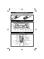
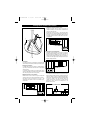
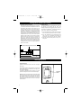
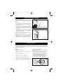
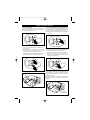
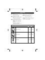
MV-VCR102UM
1/17/02
10:01 AM
Page 1
TM
Owner’s Manual
In Vehicle Entertainment System with Drop Down 6.4” TV Screen, Remote Control,
Hi-Fi VCR and Wireless Headphones
MV-1002
Patent Pending
For Operation Assistance or Technical Assistance after Reading the
Troubleshooting Guide in this Manual, Please Call Toll Free (800) 638-3600
MV-VCR102UM
1/17/02
10:01 AM
Page 2
Important Safety Instructions
This symbol indicates the presence of
high voltage in the unit. It is dangerous to
make any kind of contact with any inside
part of this product.
CAUTION
RISK OF ELECTRIC SHOCK
DO NOT OPEN
CAUTION
TO REDUCE THE RISK OF ELECTRIC SHOCK, DO
NOT REMOVE COVER (OR BACK). NO USER SERVICEABLE PARTS INSIDE. REFER SERVICING TO
QUALIFIED PERSONNEL.
CAUTION
FCC REGULATIONS STATE THAT ANY UNAUTHORIZED
CHANGES OR MODIFICATIONS TO THIS EQUIPMENT MAY
VOID THE USER’S AUTHORITY TO OPERATE IT.
IMPORTANT: One federal court has held that unauthorized
recording of copyrighted TV programs is an infringement of
U.S. copyright laws.
This symbol alerts you that important literature concerning operation and maintenance has been included with this
product.
Certain Canadian programs may be copyrighted and any
unauthorized recording in whole or in part may be violation
of these rights.
To prevent damage which may result in fire or electric
shock hazard, do not expose this appliance to rain or moisture.
Important Safeguards
1. Read Instructions: All the safety and operating instructions should be read before operating any of the components in the MovievisionTM system.
2. Retain Instructions: The owners manual should be
retained for future reference of operation. Leave this manual in the vehicle.
3. Follow Instructions: Failure to follow the operating procedures enclosed may result in unsatisfactory performance
of the system, premature component failure, injury to the
user and void the warranty from misuse, abuse and lack
of periodic maintenance.
4. VCR Service: Do not remove the cover on the VCR unit.
There are no user serviceable parts inside. Refer servicing
and repair to a qualified VCR technician.
5. TV Screen : Do not remove or disassemble the TV screen
housing or related parts. There are no user serviceable
parts inside. The TV screen housing contains a High
Voltage power converter circuit that is dangerous and can
be serviced only by a qualified technician.
7. Ventilation: Slots and openings in the cabinet of the VCR
are provided for ventilation to insure reliable operation of
the product and prevent it from overheating. These slots
and openings must not be blocked or covered at any time.
8. Object and Liquid Entry into the VCR: Never push metal
objects of any kind into the tape slot of the VCR as they
may touch electrical contact points and cause a short
circuit. Never spill any liquid on or inside the VCR.
9. Ambient Temperature: The TV screen and the VCR have been
designed to operate in a wide range of hot and cold environments. However, it is recommended that the temperature
inside the vehicle should be maintained before attempting to
operate the TV or VCR.
10. Heat: The product should be situated away from heat source
devices such as amplifiers or other products that produce
heat.
11. Wiring Harnesses: The harness should be routed in such a
way that it is not likely to be stepped on, have objects placed
on it, or hinder operation of a vehicle in any way.
6. VCR Power Source Requirement: The MovievisionTM VCR
is designed to operate from 12 volt DC automotive battery
systems only. Do not attempt to connect this unit to a
household wall socket or a 110 volt automotive step-up
converter. Irreparable damage will occur and the
warranty will be voided.
Damage Requiring Service
Damage Requiring Service: Refer the MovievisionTM system to qualified service personnel under the following conditions:
A. If objects or liquid has been spilled into the cabinet or into
the tape opening.
B. If the system does not operate normally by following the
operating instructions illustrated in this manual.
2
C. If the VCR has been kicked and the fascia has been broken.
D. When the video product exhibits a distinct change in performance, this indicates a need for service or repair.
MV-VCR102UM
1/17/02
10:01 AM
Page 3
Table of Contents
Important Safety Instructions............................................................................................................................. 2
Important Safeguards......................................................................................................................................... 2
Damage Requiring Service ................................................................................................................................. 2
Video Cassette Tape Information........................................................................................................................ 3
Remote Control Battery Install / Replace............................................................................................................ 4
VCR Controls...................................................................................................................................................... 4
Remote Control .................................................................................................................................................. 4
Programming and Setup .................................................................................................................................... 5
VCR Tape Playback............................................................................................................................................. 5
Using VCR Special Features ............................................................................................................................... 5-6
Recording........................................................................................................................................................... 6
Operating a DVD, Camcorder or Game............................................................................................................... 6
Viewing Screen Controls and Functions............................................................................................................. 7-8
Domelight Operation .......................................................................................................................................... 8-9
Headphone Operation ....................................................................................................................................... 9-10
Digital Headphone Operation.............................................................................................................................. 11
Cleaning and Maintenance.................................................................................................................................. 12
Trouble Shooting ................................................................................................................................................ 13
Replacement Parts ............................................................................................................................................. 13
Warranty............................................................................................................................................................. 14
Replacement Parts Order Form .......................................................................................................................... 15
Video Cassette Tape Information
This VCR will operate with any cassette that has the VHS mark. For best results, we recommend the use of high-quality video
cassette. Do not use poor quality or damaged tapes.
Precautions:
• Avoid Moisture. Moisture condensation may occur on the tape
if it is moved from a cold location to a warm location or visa
versa, Before using a tape with these conditions, to avoid
damage of the tape and your VCR, wait until the tape is at
room temperature and the moisture has evaporated.
• Avoid extreme heat, high humidity and magnetic fields.
• Do not tamper with the cassette mechanism.
• Do not touch the tape with your fingers.
Erase Prevention:
You can prevent accidental
erasing of a recording by
breaking off the tab on
the back edge of the
cassette.
Inserting a Cassette:
Insert the cassette in the direction as shown. Push in gently,
but continuously, on the center-back of the cassette until it is
drawn into the VCR. The VCR will automatically turn ON.
Removing a Cassette:
1. In the stop mode, press the “EJECT” button on the remote
control or press the “STOP/EJECT” button on the VCR.
The cassette will be ejected.
2. Pull the cassette out of the cassette compartment.
3. Store the cassette in its case as shown.
If you decide to record on
the tape again, cover the
hole with plastic tape
3
MV-VCR102UM
1/17/02
10:01 AM
Page 4
Remote Control Battery Install / Replace
1. Slide battery compartment cover out from back of remote
control.
2. Insert two AA batteries as diagrammed. (Supplied)
3. Slide battery compartment cover back in.
VCR Controls
Cassette Compartment For cassette insertion/removal
Hi-Fi
MOBILE VIDEO SYSTEM
HEAD
Hi-Fi Stereo VCR
POWER
Turns VCR
on and off
POWER
EJECT
EJECT
REC
Ejects
cassette
Starts
recording
REC
POWER REC
SLP
DEW
HEAT
LED
Indicators
R
STOP
PLAY
REW
FF
STOP
REW
PLAY
F.F.
Stops tape
movement
Rewinds
tape (from
stop mode)
Press to
begin
playback
Fast forwards
tape (from stop
mode)
Remote Controls
EJECT
Ejects cassette
POWER
Turns VCR on and off
POWER
EJECT
Starts Recording
REC
MENU
TRACKING UP/DOWN
ENTER DISPLAY
TRK
ENTER
PLAY
Press to begin playback
REW Rewinds tape from stop mode
STOP Stops tape movement
Adjusts cassette tracking
TV Channel UP/DOWN
SHIFT
SHIFT
MENU
Selects menu
• REC
IISTILL/SLOW
Changes TV Channels
STILL (Pause) / SLOW
Selects variable slow motion playback
DISPLAY
F. F. Fast forwards tape from stop mode
Battery Compartment
(on back)
4
MV-VCR102UM
1/17/02
10:01 AM
Page 5
Programming and Setup
To prevent excessive drain on your vehicles battery, the
MovievisionTM system will shut down 20 minutes after you turn the
ignition key to the “OFF” position.
WARNING! You must eject the tape before leaving the
vehicle for extended periods of time. DO NOT leave a
tape in the VCR! Damage to the tape and the VCR will
occur. This damage is not covered by any warranty.
VCR Tape Playback
1. Turn “ON” the ignition switch and power will be applied
to the MovievisionTM system.
2. Release the viewing screen from it’s folded and locked
position in the viewing pod.
3. Point the remote at the viewing screen and press “POWER”
or press “POWER” on the front panel of the VCR.
4. Insert a VHS tape into the tape slot of the VCR. Push the
tape case all the way in until the outer edge of the tape is
flush with the front panel of the VCR. The tape mechanism will draw the tape in to the play position. The tape
will automatically go to play mode.
5. To stop playback, press “STOP”.
CAUTION! Do not push the tape in further than needed. Once
the outer edge of the tape case is flush with the front panel
let go of the tape! The mechanism will do the rest! Forcing
the tape in will result in damage to the mechanism and force
premature service.
Manual Tracking
For best picture quality, the VCR video head must be aligned
with the recorded track on the tape; this alignment is called
tracking. Videocassettes recorded on other VCRs and videocassettes with copy protection may require some manual
adjustment.
To adjust manually, press “TRK” up or down as necessary
until the best picture possible is achieved.
Note 1: Picture distortion often occurs at the beginning of a
tape. Let the tape play for a moment to see if the distortion
clears.
Note 2: If manual tracking adjustments do not produce a
clear picture, there may be a problem with the videotape.
Using VCR Special Features
Forward and Reverse Picture Search
While in Play mode, press “REW ” or “FF
resume normal viewing press “PLAY ”.
”;
to
Forward and Reverse Fast Search
While in Play mode, press and hold “REW ” or “FF ”;
Fast Search increases the tape speed 7 times if recorded at
SP speed or 21 times for tapes recorded at SLP speed. To
resume normal viewing, release the button.
Note: While in Forward or Reverse Fast Search, audio is
muted. If streaks, blurring or horizontal jitters appear,
adjust picture with Tracking buttons.
Still (Pause) and Frame Advance (Slow)
While in Play mode, press “STILL/SLOW” to stop on a single
still frame. Press “STILL/SLOW” again to advance picture
frame by frame. To resume normal viewing, press “PLAY
”.
Note: Using Still mode for more than five minutes stresses the tape and causes undue stress on the video heads;
the VCR automatically disengages Still mode after five minutes have elapsed.
Slow Motion Playback
Press “STILL/SLOW” for Slow Motion Playback.
On Screen Menu
To access the on screen menu press the “MENU” button on
the remote control. You can access the following functions:
Record speed, Auto repeat and Audio output.
MENU
**MAIN MENU**
:Menu On or Off
SHIFT
:Shift
Cursor
RECORD SPEED.......... (SP)
AUTO REPEAT........... (OFF)
AUDIO OUTPUT..(STEREO)
CHANNEL SETUP
VCR OUTPUT CH ......(3CH)
ENTER
: ENTER Button
[SHIFT/ENTER]
[MENU]
Record Speed
Press the “MENU” button on the remote control to access the
on screen menu. Use the “SHIFT” button to select the Record
Speed function. Press the “ENTER” button to select the
desired recording speed. Press “MENU” button to exit.
Auto Repeat
The Auto Repeat function will play the video cassette tape
repeatedly. Press the “MENU” button on the remote control
to access the on screen menu. Use the “SHIFT” button to
select the Auto Repeat function. Press the “ENTER” button to
select on or off. Press the “MENU” button to exit.
5
MV-VCR102UM
1/17/02
10:01 AM
Page 6
Using VCR Special Features
Audio Output
The Audio Output function allows you to select four different
types of audio output. Press the “MENU” button on the
remote control to access the “on screen menu.” Use the
“SHIFT” button to select the Audio Output function. Press the
“ENTER” button to select the audio output desired, Left,
Right, Mono or Stereo. Press the “MENU” button to exit.
Channel Setup
When the VCR memorizes all the available channels, you can
use CH ▼/▲ buttons to select channel. Select the “CHANNEL
SETUP” using the “SHIFT” and “ENTER” button.
**MAIN MENU**
RECORD SPEED.......... (SP)
AUTO REPEAT........... (OFF)
AUDIO OUTPUT..(STEREO)
CHANNEL SETUP
VCR OUTPUT CH ......(3CH)
Note: The tracking, still (pause)/slow, recording speed and
auto repeat can only be accessed through the on screen menu
from the remote control. If you lose or damage the remote control, you will not be able to access these functions.
[SHIFT/ENTER]
[MENU]
1. Setting the Source. Before the VCR can memorize available channels you must set the signal source for your
VCR, leave “Antenna” displayed in the ANT/CABLE
screen. If you have a cable system hooked up to your
VCR, press “ENTER” to change to “CABLE/TV”.
2. Auto Channel Memory. Press to activate the auto channel memory. Your VCR will begin scanning through available channels. To interrupt, press the “MENU” button on
the remote control. When the channel number on the
screen stops changing , the VCR has finished.
3. Channel Add/Delete. You can add or delete channels that
have been memorized by the Automatic Channel Memory
function. Press “ENTER” button to add the selected channel. Press “SHIFT” button to delete the selected channel.
Note: The Auto Channel Memory function must be performed before Channel Add/Delete can be used.
VCR Output CH
This feature does not apply to Movievision.
Recording
1. Turn “ON” the ignition switch and power will be applied to
the MovievisionTM system.
2. Release the viewing screen from it’s folded and locked
position in the viewing pod.
3. Point the remote at the viewing screen and press “POWER”
or press “POWER” on the front panel of the VCR.
4. Insert a VHS tape into the tape slot of the VCR. Push the
tape case all the way in until the outer edge of the tape is
flush with the front panel of the VCR. The tape mechanism will draw the tape in to the play position. The tape
will automatically go to play mode.
5. Press the “MENU” button on the remote control to access
the on screen menu. Use the “SHIFT” button to select the
Record Speed function. Press the “ENTER” button to
select the desired recording speed. Press “MENU” button
to exit.
Note: Tape speed can be changed while recording; there
may be minor distortion but no interruption.
6. Press “REC”; the “REC” button will light.
7. To pause recording, press “STILL/SLOW”. To resume
recording, press “REC”.
8. To end recording, press “STOP”.
Operating a DVD,Camcorder or Game
1. Pod selector switch should be in the Stereo position for
best sound. (Providing the item being connected has
stereo output).
2. Turn on the auxiliary device: video game, camcorder, DVD
etc.
3. Turn on the VCR. Stop or eject the tape if one is inserted.
6
4. Use the channel UP/DOWN buttons on the remote to
select ”STEREO LINE” input. Select one station below
channel two. ”STEREO LINE” will be displayed on the
viewing screen.
MV-VCR102UM
1/17/02
10:01 AM
Page 7
Viewing Screen Controls and Functions
4. Adjusting the Screen’s Contrast: (CONTR)
Rotate the contrast control to the left or the right to
change the intensity of the dark colors compared to the
light colors and vise versa.
Rotating the control to the left (-) will make the screen
darker (dark colors will dominate). Rotating the screen to
the right (+) will make the screen lighter (lighter colors will
dominate). Adjust the contrast of the screen to your viewing preference.
5. Adjusting the Screen’s Brightness:
Rotate the bright (brightness) to the left or the right to
change background lighting of the screen from darker to
lighter and vise versa. Rotate the control to the left (-) to
make the screen darker. Rotate the control to the right (+)
to make the screen lighter. Adjust the bright control to your
desired viewing preference.
1. Infrared Eye
Point the remote control in the direction of the Infrared Eye
when accessing the functions provided by the remote control.
2. Viewing Screen Release
To release the screen, push inward on the MovievisionTM
logo and pull downward. Place the screen to the desired
viewing position.
To lock the viewing screen in the closed position, press
upward on the edge of the screen housing until the screen
locks into place (you will hear a snap sound).
3. Adjusting the Screen’s Color Intensity:
Rotate the color control to the left or right to change the
intensity of the colors on the screen. Rotation to the left (-)
will reduce the color and rotation to the right (+) will
increase the color. Adjust the color of the screen to your
desired taste.
6. Stereo/Mono Switch:
If a condition of interference arises and it can not be remedied by selecting another frequency, changing the transmit
mode from “Stereo” to “Mono” usually will eliminate interference noise. The audio performance will be reduced when
the switch is placed in the “MO” position. Return the
“ST/MO” switch to the “ST” position to re-gain the high
performance stereo sound in the headphones or the
Vehicles stereo system.
Stereo/Mono Switch
7
MV-VCR102UM
1/17/02
10:01 AM
Page 8
Viewing Screen Controls and Functions
7. Transmitter Frequency Selection:
The MovievisionTM viewing screen transmits a signal that
is received by the MovievisionTM headphones and can also
be received by the vehicle’s car radio. There are 3 frequencies available for use but only one can be used at a
time. When you are listening to a movie using the wireless
MovievisionTM headphones, it is possible that you could
travel through an area where interference between the
screen transmitter and the headphone receiver is at an unacceptable level. If this occurs, you can use the 3 position
frequency switch located in the roof housing to select a
different frequency that may have less or no interference.
Each time you change the transmitting frequency, the
headphone/car radio receiver will have to be re-tuned to
the new frequency. The 3 frequencies available for use are
89.7mhz, 90.1mhz or 90.5mhz. (For further information
on headphone tuning, consult the “Headphone Operation”
section of this manual)
Car Radio Interface:
The signal transmitted from the MovievisionTM screen can
be received by the existing FM car radio. This
listening mode provides a much higher quality of sound for
all. To listen to the MovievisionTM signal through the vehicle
stereo system, repeat the following procedures;
A. Turn “ON” the MovievisionTM system and insert a tape or
attach an auxiliary signal source to view on the screen.
B. Turn “ON” the FM radio in your vehicle and tune the
radio to one of the 3 frequencies transmitted by the
MovievisionTM system. (89.7mhz - 90.1mhz - 90.5mhz)
C. Adjust the volume and tonal qualities to suit your listening taste.
Transmitter Frequency Selection Switch
Domelight Operation
Domelight Operation:
(Applies to MovieVision flip-down screen with domelights
built-in only.)
The domelights located in the MovieVision screen housing
will illuminate whenever the vehicle doors are open just as
the original domelight did.
To activate the domelights while the vehicle is in motion,
press the domelight switch next to the desired domelight.
Note: Most American made vehicles (Ford, Chevrolet, Dodge)
have a dashboard light dimmer switch that can be rotated to
the maximum position and the domelights will illuminate.
Most Japanese or Korean made vehicles do not have this
switch and the lights will have to be turned on manually as
mentioned above.
8
Domelight
Switch
MV-VCR102UM
1/17/02
10:01 AM
Page 9
Domelight Operation (Continued)
Replacing Domelight Bulbs:
To replace a domelight bulb, repeat the following procedure.
Warning! in some cases, the domelight maybe hot, proceed
with caution.
1. Use your fingernail to pull the lever at the end of the
domelight lens forward and downward this will release the
lens to expose the bulb.
2. Use a pencil to pry out one end of the bulb then pull the
remaining end of the bulb out of it’s clip. Do not use any
metal device to remove the bulb as you may short the terminals together.
Removing Domelight Cover
3. To replace the bulb, place the metal ends of the new bulb
onto the metal clips and gently press inward until the bulb
ends are seated into the clips.
4. Replace the lens by setting the tab end into the slot and
then pressing the clip end into place.
Warning! Only replace the bulb with the same size
and wattage that you took out. Altering the size, shape
or wattage will result in a damaged housing (melting).
Use only Sylvania or GE model DE3021 for replacements.
Removing Bulb
Headphone Operation
Your MovievisionTM entertainment system is supplied with two (2) MovievisionTM headphones. The correct operation, care and
maintenance of the headphones is critical to their ability to provide the user with a lifetime of operation. Misuse, abuse and
neglect of the headphones will result in poor performance and premature failure. Please read through the simple operation and
maintenance instructions enclosed.
WARNING!
• Do not throw the headphones.
• Do not get the headphones wet or submerse them in any
liquid.
• Do not use the headphones as a hammer.
• Do not step, stand or sit on the headphones.
1. Install the Batteries (AAA Type)
To install the “AAA” batteries supplied, repeat the following
procedure:
A. Hold the headphones in one hand and place your thumb
onto the gripping arrow on the battery holder cover.
B. Press down on the gripping arrows while pulling downward on the battery door. Slide the door away from the
headphones to expose the battery holder cavity.
C. Place the batteries into the holder following the directions
engraved inside the holder. Observe battery polarity.
• Do not lay heavy objects on the headphones.
• Refrain from turning the volume of the headphones to the
maximum position, this may result in ear damage.
9
MV-VCR102UM
1/17/02
10:01 AM
Page 10
Headphone Operation (Continued)
3. Adjust the Headphones to Fit Your Head
Repeat the following to adjust the headband to fit:
A. Spread the ear pads apart and place the headphones on
your head. Observe the “L” and “R” indicators.
B. Grab the ear pads and use your thumb and forefinger to slide
the adjusters up or down until a comfortable fit is achieved.
Standard Headphone Operation
1
PWR
OFF RAD MOV
3. Turn OFF the Headphones when Finished
The batteries supplied with your MovievisionTM headphones
will last for approximately 10 hours of continuous use.
Forgetting to turn “OFF” the headphones, when not in use,
will decrease the battery life.
1. Headphone Radio Operation
Your MovievisionTM headphones can be used as an FM radio
receiver. Repeat the following procedures to listen to FM
radio broadcasts.
A. Move the Power/Selector switch (1) from the OFF position to the RAD (Radio) position.
B. Rotate the tuning knob (2) to the desired FM radio station.
Note: FM radio stations are always received in Stereo Mode.
C. Adjust the volume knob (3) to the desired volume level.
1
PWR
OFF RAD MOV
1
PWR
OFF RAD MOV
2. Listening to What is on the Viewing Screen
To use the MovievisionTM headphones with the source selected (FM Stereo/Video) repeat the following procedures.
A. Move the Power/Selector switch (1) to the MOV (Movie)
position.
B. Rotate the tuning knob (2) until the headphone sound
matches what is showing on the viewing screen.
C. Adjust the volume knob (3) to the desired volume level.
Note: If the transmitting frequency has been changed in the
screen housing, repeat step “B” to re-tune the headphones.
10
4. Connecting a Second Set of Headphones
Your MovievisionTM headphones have a plug receptacle located at the bottom of the “R” ear pad. (4) A second set of personal type headphones (Must have 3.5 mini male type plug)
can be connected at this point.
Note: When a second pair of headphones are attached, the
tuning and audio level is controlled by the MovievisionTM
headphone.
MV-VCR102UM
1/17/02
10:01 AM
Page 11
Digital Headphone Operation
1. Turn On the Headphones:
To turn on the headphones, press the ”PWR” button on the
right side ear pad. The digital display will show radio station
digits when the headphone is on.
2. Tuning an FM Radio Station:
A. Press the ”UP” or ”DOWN” button to manually tune in an
FM radio station.
B. Press and hold the ”UP” or ”DOWN” button for one second
then release. The radio tuner will search up or down the
radio band for the next strongest FM radio station.
Note: FM radio stations are always received in Stereo Mode.
C. Adjust the volume knob to the desired volume level.
Volume Control
3. Listening to What Is Displayed on the Viewing Screen:
On the right ear pad are 3 pre-programmed buttons marked
1, 2 and 3. These buttons will tune the headphone radio to the
exact MovieVision signals. Press the buttons one at a time
until what you hear in the headphones is what is displayed on
the viewing screen.
4. Turn Off the Headphones when you are Finished:
A. Press the ”PWR” button to turn off the headphones.The
display will be blank when the headphones are off.
B. The batteries supplied with your MovieVision headphones
will last for approximately 10 hours of continuous use.
Forgetting to turn off the headphones when they are not in
use will decrease the battery life.
5. Connecting a Second Set of Headphones
Your MovievisionTM headphones have a plug receptacle located at the side of the “L” ear pad. A second set of personal
type headphones (Must have 3.5 mini male type plug) can be
connected at this point.
Note: When a second pair of headphones are attached, the
tuning and audio level is controlled by the MovievisionTM
headphone.
Plug for
second pair
of headphones
11
MV-VCR102UM
1/17/02
10:01 AM
Page 12
Cleaning and Maintenance
Servicing:
Should your MovievisionTM VCR become inoperative, do not
try to correct the problem by yourself. There are no user
serviceable parts inside. Remove the unit from the vehicle
and take it to an authorized MovievisionTM service facility.
Cabinet Cleaning:
The front panel of the MovievisionTM VCR can be cleaned
with a soft cloth that has been immersed in luke warm
water and wrung dry. Never use alcohol or solvents of any
kind to clean your MovievisionTM VCR. Damage will result.
Screen Maintenance:
During the normal course of use, the plastic housing parts
will get dirty, dusty and the viewing screen will get finger
prints on it. The viewing screen and related plastic housing
parts can be safely cleaned using a dampened soft cotton
cloth with a small amount of dish washing soap rubbed into
it. An overly wet cloth that has too much soap in it will
cause you trouble. Repeat the following procedures to correctly clean the viewing screen and related plastic parts.
A. Completely soak a soft cotton cloth and rub a small
amount of dish washing soap into it.
B. Twist the cloth tightly and wring out as much moisture as
possible
C. Lightly, rub the cloth on the viewing screen and related
plastic parts to remove the dust, dirt and fingerprints.
D. Wipe off the excess soap residue with a clean dampened
cloth and let air dry.
WARNING!
• Do not rub the viewing screen dry.
• Do not rub hard on the viewing screen as you will scratch
it and or damage the screen.
• Do not rub on the screen in circular motions.
• Do not rub the screen with your fingers to clean it.
• Do not use ANY chemicals on the viewing screen or related
plastic parts such as glass cleaners,furniture polish, specialized
automotive cleaners, rubbing alcohol, thinners or solvents.
12
VCR Head Cleaning:
The use of poor quality or old worn tapes can still leave
deposits on the tape head preventing high picture and sound
quality. If a streaky or snowy picture (or no picture at all)
appears during “playback”, the heads of your VCR may need
to be cleaned.
1. Visit your local audio/video store and purchase a good
quality VHS head cleaner and follow the directions supplied to clean the heads.
2. If a commercial grade video head cleaner does not solve
the picture quality problem, your heads may need professional cleaning. Consult your local video repair center
for professional service.
When using head cleaning cassette, read all instructions
carefully; incorrect head cleaning can permanently damage the video heads.
DO NOT INSERT ANY OBJECTS INTO THE CABINET SLOTS;
CONTACT WITH A VOLTAGE POINT INSIDE THE VCR CAN
CAUSE DANGEROUS SHOCK OR MAY SHORT OUT PARTS
AND CAUSE FIRE OR ELECTRIC SHOCK.
Headphone Maintenance:
There are no user serviceable parts in the headphones
(Except the batteries) Do not disassemble the
headphones for any reason. Replace the batteries with high
quality Alkaline “AAA” batteries as needed.
MV-VCR102UM
1/17/02
10:01 AM
Page 13
Trouble Shooting
Problem: No power
Solution: • Make sure the ignition switch is in the on position.
• Check the power connection.
• Check the remote for good batteries.
Problem: Videocassette cannot be inserted
Solution: • Press “EJECT” to see if a cassette is already in the
VCR.
• Make sure the video cassette is window-side up,
with the arrow pointing toward the VCR.
Problem: No picture, distorted picture on playback.
Solution: • Try another videocassette to see if it plays back
properly.
• Press “TRK” up or down to adjust the picture.
• Set INPUT MODE on TV to AUX IN, VIDEO or
EXTERNAL.
• Make sure the TV is working properly.
• If the problem occurs on more than one tape, try
using a video head cleaner cassette.
Problem: Streaks (noise) or jitter with the VCR in Still mode.
Solution: Press “TRK” up or down to adjust the picture.
Problem: VCR will not Play, Rewind or Fast Forward.
Solution: • Check if the VCR is in Still mode.
• Check if the cassette has been rewound.
Problem: The VCR motor continues to run even after “STOP”
is pressed.
Solution: This is normal: the video heads run for five minutes
even after a cassette has been stopped.
Replacement Parts for MovieVisionTM Systems
ORDER BY MAIL
POWER
REC
MODEL #
PRICE
Standard Headphones
HP-100
$79.95 EA.
Digital Headphones
HP-200
$99.95 EA.
MV-RM102
39.95 EA.
EJECT
MENU
ENTER DISPLAY
SHIFT
DESCRIPTION
TRK
IISTILL/SLOW
Remote Control
13
MV-VCR102UM
1/17/02
10:01 AM
Page 14
Warranty
ONE (1) YEAR LIMITED WARRANTY
Magnadyne Corporation or its authorized agents will within 1 year from the date of sale to you, repair, replace
or refund the retail sales price of said product or any part thereof, at the option of the Magnadyne Corporation
or its authorized agents, if said product or part is found defective in materials or workmanship, when properly connected and operating on the correct power requirements designated for the specific product. This
warranty and Magnadyne Corporation or its authorized agents obligations hereunder do not apply where the
product was; damaged while in the possession of the consumer, subjected to unreasonable or unintended
use, not reasonably maintained, utilized in commercial or industrial operations, or serviced by anyone other
than Magnadyne Corporation or its authorized agents, or where the warning seal on the product is broken or
the power and/or plugs are detached from the unit. Magnadyne Corporation or any of its authorized agents
will not assume any labor costs for the removal and re-installation of any product found to be defective, or
the cost of transportation to Magnadyne Corporation or its authorized agents. Such cost are the sole responsibility of the purchaser.
This warranty does not cover the cabinet appearance items or accessories used in connection with this product, or any damage to recording or recording tape, or any damage to the products resulting from improper
installation, alteration, accident, misuse, abuse or acts of nature.
MAGNADYNE CORPORATION OR ITS AUTHORIZED AGENTS SHALL NOT BE LIABLE TO ANYONE FOR CONSEQUENTIAL OR INCIDENTAL DAMAGES OR CLAIMS EXCEPT THOSE ACCORDED BY LAW. NO EXPRESSED
WARRANTY OR IMPLIED WARRANTY IS GIVEN EXCEPT THOSE SET FORTH HEREIN. NO IMPLIED WARRANTY SHALL EXTEND BEYOND 1 YEAR FROM THE DATE OF SALE.
This warranty extends only to the original purchaser of the product and is not transferable.
Some states do not allow limitations on how long an implied warranty lasts, and some states do not allow
the exclusion or limitation of incidental or consequential damages, so the above limitations or exclusion may
not apply to you. This warranty gives you specific legal rights, and you may have other rights that vary from
state to state.
Defective merchandise should be returned to the original point of purchase or secondly, to Magnadyne
Corporation, 1111 W. Victoria Street, Compton CA 90220, or 2061 Cohen Street, Montreal, Quebec H4R 2N7.
Return Authorization must be obtained before sending, or merchandise may be refused.
14
MV-VCR102UM
1/17/02
10:01 AM
Page 15
Replacement Parts Order Form
Send Orders To: Magnadyne Corporation
ATTN: Consumer Parts Sales
P.O. Box 5365
Carson, CA 90749-5365
We Accept Checks, Money Orders, Visa and Master Card
Make Checks Payable to: Magnadyne Corporation
SHIP TO: (No P.O. Boxes)
LAST NAME
FIRST NAME
INITIAL
STREET ADDRESS (IF PAYING WITH A CREDIT CARD, YOUR BILLING ADDRESS IS REQUIRED)
CITY
STATE
ZIP CODE
DAY TIME PHONE NUMBER
CREDIT CARD INFORMATION:
CARD TYPE:
VISA
MASTER CARD
CARD NUMBER
EXPIRATION MONTH
YEAR
NAME AS IT APPEARS EXACTLY ON YOUR CREDIT CARD
Part #
Description
Qty.
Price Each
TOTAL
Shipping and Handling
Subtotal + Tax
Up to $20.00
20.01 to 30.00
30.01 to 45.00
45.01 to 70.00
Over 70.01
Add
$5.00
5.95
6.50
6.95
7.95
Sales Subtotal = ________ . ______
California Residents Add Sales Tax = ________ . ______
Shipping and Handling (See Chart) = ________ . ______
TOTAL = ________ . ______
No C.O.D.’s
On regular orders please allow 4-5 weeks for delivery. Please give a shipping address where this order
may be delivered between the hours of 9 A.M. and 5 P.M. weekdays. If UPS is unable to deliver, your order will be
returned and additional shipping charges will be required.
15
MV-VCR102UM
1/17/02
© Copyright 2001
Magnadyne Corporation
10:01 AM
Page 16
MV-VCR102UM
Rev. B 12-8-00