1
Reference Manual
This page intentionally left blank
10%
20%
30%
40%
50%
60%
70%
80%
90%
100%
Table Of Contents
Introduction..........................................................5
Welcome!...................................................................................................... 5
About the iMultiMix16 USB .............................................6
iMultiMix16 USB Key Features ................................................................ 6
How to Use This Manual ...................................................8
A Few Words for Beginners..............................................9
Chapter 1: Getting Started ................................11
Hooking up the iMultiMix16 USB ...................................11
Using Proper Cables ..........................................................12
Setting Levels ......................................................................12
Chapter Two: A Tour of the MultiMix.............13
Patchbay...............................................................................13
1) MIC INPUTS (Channels 1 – 8) ........................................................... 13
2) LINE/GUITAR INPUTS (Channels 1 – 2)...................................... 13
3) LINE INPUTS (Channels 3 – 8)......................................................... 14
4) LINE INPUTS (Channels 9 – 16)....................................................... 14
5) DIGITAL OUT Jack............................................................................. 14
6) PHONES Jack........................................................................................ 14
7) AUX RETURNS.................................................................................... 14
8) AUX SENDS.......................................................................................... 15
9) ALT 3/4 OUT........................................................................................ 15
10) 2-TRACK .............................................................................................. 15
11) MAIN MIX OUT................................................................................ 15
12) CTRL RM OUT................................................................................... 15
Channel Strips ....................................................................15
1) Fader ........................................................................................................ 15
2) MUTE / ALT 3/4 ................................................................................. 16
3) PFL / SOLO .......................................................................................... 16
4) PAN or BAL ........................................................................................... 16
5) AUX ......................................................................................................... 16
6) EQ ............................................................................................................ 17
Master Section.....................................................................17
1) MAIN MIX Fader.................................................................................. 17
2) ALT 3/4 Fader ....................................................................................... 17
3)
/ 2TK TO MIX........................................................................... 17
4) ALT 3/4 TO Mix ................................................................................... 17
5) SOLO MODE........................................................................................ 18
6) HDPH / CTRL RM .............................................................................. 18
7) MIX Switch ............................................................................................. 18
8) ALT 3/4 Switch...................................................................................... 18
9)
/ 2TK Switch ............................................................................... 19
10) AUX RET A LEVEL.......................................................................... 19
11) EFFECTS / AUX RET B LEVEL................................................... 19
12) LED Meters .......................................................................................... 19
13) POWER Indicator ............................................................................... 19
14) +48V Indicator..................................................................................... 19
1
Table Of Contents
iPod Section ............................................................................................. 20
1) BACKLIGHT......................................................................................... 20
2) LED Meters ............................................................................................ 20
3) LIMITER ................................................................................................ 20
4) iPod Control Buttons ............................................................................ 20
5) Jog Wheel ................................................................................................ 20
6) iPod RECORD Fader............................................................................ 20
7) iPod PLAYBACK Fader ....................................................................... 21
8) iPod TO MIX ......................................................................................... 21
9) iPod TO CTRL ROOM........................................................................ 21
10) iPod INPUT MON TO CTRL ROOM ........................................... 21
Rear of the Mixer................................................................22
1) Power Input............................................................................................. 22
Power Supply Unit:..................................................................................... 22
2) POWER ON........................................................................................... 22
3) PHANTOM ON.................................................................................... 22
4) USB Port.................................................................................................. 22
Chapter Three: Digital Effects
Processor ...............................................................23
Effects Section Components ............................................23
1) Program Selection Knob....................................................................... 23
2) PROGRAM LED Display.................................................................... 23
3) CLIP Indicator........................................................................................ 23
4) SIG Indicator.......................................................................................... 23
Effect Descriptions.............................................................23
HALL ........................................................................................................... 23
ROOM ......................................................................................................... 23
PLATE ......................................................................................................... 23
CHAMBER ................................................................................................. 23
CHORUS ..................................................................................................... 24
FLANGE..................................................................................................... 24
DELAY ........................................................................................................ 24
PITCH.......................................................................................................... 24
MULTI & MULTI 2................................................................................... 24
Chapter Four: Applications...............................25
Simple Recording Setup ...................................................25
Recording to iPod...............................................................25
Simple Live Setup...............................................................26
Using Additional External Audio Sources ....................26
Digital Output to a Digital Recorder .............................26
Using the iMultiMix16 USB with a Computer..............27
Sending and Receiving Audio Data.......................................................... 27
Precautions when using the USB connection......................................... 27
Connection instructions for Windows (XP, 2000, ME,
and 98 Second Edition) ............................................................................. 27
Connection instructions for Macintosh (OS X only)............................ 28
2
Table Of Contents
Chapter Five: Troubleshooting ........................29
Chapter Six: Specifications ...............................33
Chapter Seven: Block Diagram ........................35
Glossary .................................................................37
Warranty/Contact Alesis ....................................39
Alesis Limited Warranty............................................................................. 39
Alesis Contact Information....................................................................... 40
3
Table Of Contents
This page intentionally left blank.
4
Introduction
Welcome!
Thank you for making the Alesis iMultiMix16 USB a part of your
studio. Since 1984, we've been designing and building creative
tools for the audio community. We believe in our products,
because we've heard the results that creative people like you have
achieved with them. One of Alesis' goals is to make high-quality
studio equipment available to everyone, and this Reference Manual
is an important part of that. After all, there's no point in making
equipment with all kinds of capabilities if no one explains how to
use them. So, we try to write our manuals as carefully as we build
our products.
For more effective service and
product update notices, please
register your iMultiMix USB
mixer online at:
http://www.alesis.com/account/
productregistration.php
The goal of this manual is to get you the information you need as
quickly as possible, with a minimum of hassle. We hope we've
achieved that. If not, please drop us an email and give us your
suggestions on how we could improve future editions of this
manual.
We hope your investment will bring you many years of creative
enjoyment and help you achieve your musical goals.
Sincerely,
The People of Alesis
5
Introduction
About the iMultiMix16 USB
The iMultiMix USB consoles are a versatile series of mixers
designed to perform well in the live and home studio realm. They
are the latest in the large family of Alesis audio mixers. We’ve
come a long way since introducing our first mixing console in
1989. Since that time audio technology has grown in leaps and
bounds, pushing quality and driving down prices. Only a few years
ago, you wouldn’t have been able to buy a mixer this powerful for
such an affordable price. Just take a look at the key features listed
below, and you’ll see that you have just made an incredible addition
to your home studio or live setup.
The iMultiMix USB console gives you just about everything you
need to create polished, professional-sounding mixes. When
designing this unit, our goal was to give you as much control over
your mixes as possible without requiring a wealth of extra
equipment. That’s why we added tools like the digital effects
processor, the mic preamps, the USB computer interface, the
digital out, and the full-featured iPod interface. And with a
multitude of ways in which to connect other equipment and
instruments, the iMultiMix USB offers endless possibilities.
iMultiMix16 USB Key Features
8 channels with mic/line inputs, 4 stereo channels
with line inputs
Switchable guitar inputs on channels 1 & 2 – these
high-impedance inputs are specifically designed for electric
guitars and basses.
Clean and powerful preamps – up to 50dB of preamp
gain for capturing quiet sources. Globally switched
phantom power.
3-band EQ per channel – a potent tool for sonically
shaping each channel to get that perfect mix.
1 pre/post-fader switchable aux send per channel –
gives you control over the level of the pre- or post-fader
signal being routed to an external device.
1 post-fader aux send/effects send per channel – a
control for the signal being routed to another external
device or to the onboard effects processor.
Integrated iPod dock – allows you to record your mix
directly to your iPod and to play back from your iPod
through the mixer.
iPod Limiter – ensures that your iPod recordings are
always clean, crisp, and never distorted.
Internal digital effects processor with 100 preset
effects and an easy-to-read display – includes a variety
of reverbs, delays, choruses, flangers, a pitch transposer and
multiple combinations of these.
Control room output level – provides control over the
separate control room output
6
Introduction
2-track send and return – lets you mix your audio to tape
or other media and to add a tape deck or CD player to the
mix.
Stereo USB input and output – routes the main output
and the 2-track return through the USB port in crystalclean, 16-bit, 44.1 kHz stereo digital audio. Use the
iMultiMix USB as a high-quality soundcard for recording
and playback with Windows and Macintosh computers.
PFL/Solo in place functionality per channel – isolates a
channel with a single push of a button.
Mute/Alt 3/4 assign per channel – lets you mute a
channel and, at the same time, route its signal to the mixer’s
ALT 3/4 output—a separate stereo bus.
Independent Main Mix and Alt 3/4 levels – permits you
to separately command the levels of the iMultiMix USB’s
two stereo buses.
44.1 kHz S/PDIF digital out – sends the digital stereo
signal directly to a DAT, DVD or other recording device
that can accept a S/PDIF signal.
7
Introduction
How to Use This Manual
This manual is divided into the following sections describing the
various functions and applications for the iMultiMix USB console.
While it's a good idea to read through the entire manual once
carefully, those having general knowledge about mixing should use
the table of contents to look up specific functions.
Chapter 1: Getting Started shows you how to include the iMultiMix
USB in your audio setup for recording, computer interfacing, and
live applications. We’ve included a hookup diagram, guidelines for
which cables to use and the vital steps you must take to set levels
properly.
Helpful tips and adv
shaded box like this
Helpful tips and advice are
highlighted in a shaded box
like this.
Chapter 2: A Tour of the iMultiMix USB describes the iMultiMix
USB piece by piece. This chapter also features diagrams of the
mixer to help you find each component as you read about it.
Chapter 3: Digital Effects Processor explains the effects provided by
the on-board digital effects processor. If you want to know what a
certain effect will do to your sound before you select it, this is
where you should look.
Chapter 4: Applications outlines a number of scenarios in which
you can use the iMultiMix USB, including some tips on what
goes where when you’re hooking everything up.
Chapter 5: Troubleshooting can give you a hand if you’re experiencing
problems with your mixer. You’ll find that most issues can be
resolved simply and quickly with the push of a button.
Chapter 6: Specifications and Chapter 7: Block Diagrams are full of
technical information for the more techie users.
And at the end of this manual you’ll see a glossary of common
mixing-related terms and a page about the iMultiMix USB’s
warranty.
8
When something important
appears in the manual, an
exclamation mark (like the
one shown at left) will appear
with some explanatory text.
This symbol indicates that
this information is vital when
operating the iMultiMix USB.
When something im
manual, an exclama
shown at left) will a
explanatory text. Th
this information is v
IMultiMix-12FX.
Introduction
A Few Words for Beginners
We realize that some of you who have purchased the iMultiMix
USB are fairly new to the art of mixing, and we’ve written this
manual with that in mind. We designed the iMultiMix to be both
powerful and easy enough to use that even a beginner can quickly
pick up the basics.
Many mixer manuals—and manuals for just about any electronic
instrument for that matter—are full of complicated terminology
and incomplete instructions that presume a lot of experience on
the part of the reader. We try to avoid that with this manual. True
enough, you will find all the technical lingo and specifications you
can handle in here, but we do our best to make this accessible to
you.
One of the most important
things you’ll do before you
begin a mixing session is to
set the levels. Be sure to refer
to the instructions on page
12.
Beginners will find several elements of this manual especially
useful. Keep your eye out for the tips found in the gray boxes on
the right side of the page. Be sure to check out the hookup
diagrams on page 11, which will give you some ideas on how to fit
the mixer into your audio setup after you’ve taken a tour of the
mixer in Chapter 2. And if you come across any terms that you
haven’t seen before, the glossary probably can help you out.
9
Introduction
This page intentionally left blank.
10
1 Getting Started
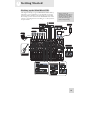
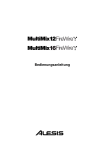
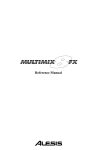
Hooking up the iMultiMix16 USB
This diagram will help you get the iMultiMix16 USB hooked up
and ready to go. The equipment you use depends on personal
preference and on whether you’re performing live or recording.
For example, you’ll see below that the MAIN MIX OUT can be
routed to a recording device for recording, or to a PA system for
live performance.
Be sure to follow the
guidelines for which cables to
use (further down this page)
and the procedure for setting
levels (on the next page)
before you begin mixing.
Headphones
Effects Processor
Power Outlet
Mixdown Tape Deck
DAT Recorder or other S/PDIF device
Microphones
iPod
Computer
USB cable
Power Amplifier
Guitar or other
mono instrument...
Studio Monitors
Keyboard
FOR RECORDING:
LIVE:
Digital Audio Workstation
PA System
Sampler
ADAT
Or other line-level stereo instrument...
Or other device...
11
1
Getting Started
Using Proper Cables
When connecting instruments and other equipment to the
iMultiMix, it’s important that you use the appropriate types of
cables. Here are some simple but important guidelines:
For the mic inputs, use XLR cables.
For the line inputs and all other 1/4” connections, use 1/4”
mono TRS cables.
Use stereo RCA cables for the 2-track in and out.
Use a USB cable to connect the USB port to a computer.
Do not use a USB hub, as hubs can introduce timing
glitches in USB communication.
For the S/PDIF Digital out, we suggest that you use a
coaxial cable that is specifically designed for S/PDIF
applications. These cables are better suited for high
frequency (digital) signals and are unbalanced, shielded
coaxial cables with shielded RCA connectors on each end.
Better to get the high quality S/PDIF cables and save
yourself some unnecessary grief.
Setting Levels
Before you can begin mixing different audio sources with your
iMultiMix USB, you must set the level for each channel you’re
using. This helps to prevent distortion and clipping. Here’s how:
1. Slide the channel fader to unity gain (0).
2. Turn the AUX SEND and GAIN controls all the way down,
and turn the EQ knobs to the center detent (you’ll feel a click).
3. Connect the source of the signal to the channel’s input.
4. Press the PFL / SOLO switch on the channel.
5. Make sure the SOLO MODE switch in the master section is
set to SOLO.
6. Play the instrument at a normal level and watch the LED
meters in the master section.
7. Adjust the channel’s gain until the LED meters remain at or
very close to 0 and do not exceed +6dB.
8. If you need to apply EQ, do so and check the meter again.
12
2 A Tour of the iMultiMix16 USB
In this chapter, you’ll learn all about the iMulitMix16 USB’s
components (except for the digital effects processor, which is
explained in the next chapter). Please refer to the diagrams as you
read each section to see which components we’re talking about.
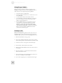
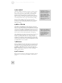
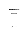
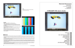
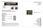
Patchbay
At the rear portion of the top of the iMultiMix USB, you’ll find
the patchbay. This is where you plug in instruments, signal
processors, multitrack recorders and other devices. Whatever you
need to connect to the mixer, this is where it’s done. In the
following paragraphs, we tell you all about the inputs, outputs,
switches and knobs you see in this section of the mixer.
1
1
1
1
1
1
1
1
2
2
3
3
3
3
3
3
5
6
4
4
7
4
8
9
10
4
11
12
1) MIC INPUTS (Channels 1 – 8)
The iMultiMix USB uses standard XLR-type mic inputs. These
provide +48V phantom power that you can turn on and off with
the Phantom On switch located on the rear of the mixer. You
probably will have to turn on the phantom power when you’re
using most condenser mics, as these usually require the extra
voltage (unless the mic has its own power source, such as a
battery). Dynamic and ribbon mics don’t require phantom power
and are unaffected when the power is on.
These high-quality mic inputs also feature up to 50dB of preamp
gain that you can adjust with the Gain knob.
Another useful feature of these mic inputs is a high-pass filter
(HPF) that can be turned on and off with the HPF switch. When
you activate this switch, all frequencies below 75Hz are cut from
the signal. This is useful for mic or line signals that don’t have
much bottom end, such as vocals, snares, cymbals and electric
guitar. You’ll want to leave this inactivated for instruments like
basses and kick drums.
2) LINE/GUITAR INPUTS (Channels 1 – 2)
These line inputs, marked LINE IN, are balanced 1/4” jacks that
offer the same 50dB of preamp gain and the high-pass filter
provided by the mic inputs (however, phantom power does not
apply to line inputs). If you find that your instrument has a weak
line signal, just plug it into channels 1 – 8 and crank it up with the
Gain knob. These first two inputs accept line-level instruments
such as keyboards and drum machines as well as guitars. With the
Although chances are your
microphones will work fine
with these mic inputs, we
recommend that you do some
checking up on the type of
microphone you’re using,
especially if it’s one of the
older vintage models. Verify
that your microphone
requires phantom power and
make sure its output is low
impedance, balanced and
floating.
Always connect your
microphones before
activating phantom power.
Microphones tend to be very
sensitive, and the sudden
power surge can do
permanent damage to the
mic’s circuitry. It’s also a
good idea to lower mixer
levels before you activate
phantom power.
13
2
A Tour of the iMultiMix16 USB
MIC/LINE | GUITAR button depressed, these inputs can
support high-impedance (1MΩ) active guitar or bass pickups using
balanced ¼” plugs.
3) LINE INPUTS (Channels 3 – 8)
These line inputs, marked LINE IN, are balanced 1/4” jacks that
offer the same 50dB of preamp gain and the high-pass filter
provided by the mic inputs (however, phantom power does not
apply to line inputs). These inputs accept line-level instruments
such as keyboards and drum machines. If you find that your
instrument has a weak line signal, just plug it into channels 1 – 8
and crank it up with the Gain knob. Note that the first two
channels are specially designed for handling guitar and bass signals
(see #2 above).
4) LINE INPUTS (Channels 9 – 16)
Unlike channels 1 – 8, the line inputs on channels 9 – 16 are stereo
inputs that have left and right inputs. If you’re using one of these
channels as a mono input, plug your instrument into the left input.
Channels 9 – 16 don’t have the extra gain found on channels 1 – 8
because most line-level instruments don’t require the extra boost.
Synthesizers and other electronic instruments will work especially
well on these channels. These inputs are also good for connecting
CD players or tape decks, as these audio sources don’t require
extra gain.
5) DIGITAL OUT Jack
The digital output jack is used to send the 44.1 kHz stereo audio
signal to an Alesis Masterlink or any other recording device such as
a DAT recorder or a PC with an S/PDIF enabled sound card
installed.
Always use a high quality cable when connecting the DIGITAL
OUTPUT JACK to your recording device. We recommend that
you use a cable that is specifically designed to carry a digital signal
and does not exceed 5 meters (16.4 ft) in length.
Any audio signal that is
routed to the MAIN
OUTPUTS will also be sent
out of the DIGITAL OUTPUT
jack. The level is controlled
by the MAIN FADERS. The
DIGITAL OUTPUT mirrors
the output from the MAIN
OUTPUTS.
6) PHONES Jack
The headphone jack accepts a 1/4” plug. If your headphones are
1/8”, you can find a 1/8”-to-1/4” adapter in most electronics
stores.
7) AUX RETURNS
These are the 1/4” jacks where you connect the outputs of an
external effects processor or other audio source. Each aux return
gives you 15dB of gain that can be controlled by the AUX RET A
and EFFECTS / AUX RET B LEVEL knobs in the mixer’s
output section.
14
If you are using an effects
device with only a mono
output, plug it into the left
return of STEREO AUX
RETURN. It will appear in
the center of the stereo
spectrum.
A Tour of the IMultiMix16 USB
2
8) AUX SENDS
And this is the 1/4” jack where you connect the line that’s going
into the input of an external effects processor. The aux sends give
you 10dB of gain that can be controlled in the AUX section of
each channel input.
9) ALT 3/4 OUT
These jacks are the outputs for the iMultiMix USB’s extra stereo
bus. This signal includes channels whose MUTE / ALT 3/4 switch
is activated.
10) 2-TRACK
The 2-TRACK IN and OUT jacks are standard RCA jacks. You’ll
use the OUTs for mixing to a tape deck or other recorder. With
the INs you can bring in a signal, which can be monitored and
even added to the main mix via the 2TK TO MIX switch in the
master section of the mixer.
11) MAIN MIX OUT
These 1/4” jacks are where the signal on the main mix bus leaves
the mixer. From there you can send it to a recorder or a PA system.
The level of this signal is controlled by the MAIN MIX fader.
12) CTRL RM OUT
You can use these 1/4" jacks to send the control room signal to
the input of the amplifier driving your monitors or headphones.
This output can carry several different signals, depending on which
source you have selected in the master section of the mixer.
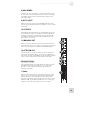
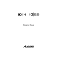
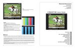
Channel Strips
The eight channel strips are virtually identical to each other, with
the only difference being that channels 1 – 8 are mono and
channels 9 – 16 are stereo. Each channel strip contains the
following components.
1) Fader
6
5
4
3
2
1
The fader controls how much of the signal from the mic or line
inputs is sent to the channel. To adjust the level, simply slide the
fader up and down to the desired level. In the lowest position,
levels are cut completely, and in the uppermost position you get an
additional 10dB of gain. When the fader is at 0, it is at unity gain,
where the level of the output equals the level of the input.
15
2
A Tour of the iMultiMix16 USB
2) MUTE / ALT 3/4
This switch has two purposes. The mute function is pretty selfexplanatory: when you press the switch, the channel’s output is no
longer routed to the main mix output. The second purpose of this
switch is that in addition to muting a channel, it also routes it to
the ALT 3/4 OUT found in the patchbay. This is where you get
the iMultiMix’s extra stereo bus. If you don’t have anything
connected to the ALT 3/4 OUT, the switch acts only as a mute
button. If you do have something connected—say, a multitrack
recorder—this button acts as a signal router.
6
5
3) PFL / SOLO
The PFL / SOLO switch allows you to single out a channel so you
can make adjustments to it before you run it into the main mix.
This is useful for setting an instrument’s gain or EQ and for
troubleshooting. PFL stands for “pre-fade listen.” In other words
this switch lets you hear the signal before it is affected by the fader.
This switch is post-EQ.
4
3
2
4) PAN or BAL
This control—labeled PAN on the mono channels and BAL on
the stereo channels—lets you assign the channel to a particular
spot within the stereo spectrum. If you turn this knob to the left,
you can hear the signal move to the left, and if you turn it to the
right…you get the picture. The pan controls do this by adjusting
the amount of the signal being sent to the left main mix bus versus
the right main mix bus. The balance controls do it by controlling
the relative balance of the left and right channel signals being sent
to the left and right main mix buses.
5) AUX
Here you’ll find knobs that control the levels of aux sends A and
B. AUX A is either pre-fader or post-fader, depending on the
position of the PRE / POST switch. When the switch is in the
raised position, the aux send is pre-fader. When the switch is
depressed, the aux send is post-fader.
What does all this mean? In POST mode the aux send is affected
by the fader, EQ and HPF settings. In PRE mode the aux send is
affected only by the EQ and HPF settings. POST mode is
generally used for sending the signal to an external effects device
(so that the fader controls the signal level), and PRE mode is
usually used for cue sends (for example, sending a signal to
headphones while recording, for which you may not want the fader
to alter the channel’s level).
AUX B is always post-fader, as indicated by the word “POST” to
the right of this knob. Like AUX A, AUX B can be used for
routing signals to external devices. And when you are using the
16
1
A Tour of the IMultiMix16 USB
2
onboard effects processor, AUX B is used to control the level of
the channel’s signal being routed to the processor.
6) EQ
The iMultiMix gives you three bands of EQ per channel. Using
these knobs, you can tailor the channel’s signal by boosting some
frequencies and cutting others. The LO and HI controls are
shelving controls with fixed frequencies of 80 Hz and 12 kHz
respectively. The MID control has a peaking response fixed at 2.5
kHz.
“Shelving” means that the mixer boosts or cuts all frequencies past
the specified frequency. “Peaking” means that frequencies above
and below the specified frequency fall off, forming a peak in a
graphical representation.
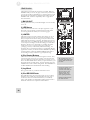
Master Section
The Master Section is the heart of the mixer, where the channel
inputs and aux returns all are mixed together and routed in various
ways.
13 14
10
1) MAIN MIX Fader
The signals from all channels and aux sends—excluding those that
are muted—are sent to the main mix. The MAIN MIX fader is the
one you’ll use to control the overall level of those combined
signals. This fader affects the levels of the signals sent to the
MAIN MIX OUT, the DIGITAL OUT (12FXD and16FXD
models only) and the 2-TRACK OUT. In its lowest position the
signal is cut off completely, and in the uppermost position you get
an additional 10dB of gain. In the 0 position the fader is at unity
gain.
2) ALT 3/4 Fader
11
12
3
7
8
9
4
1
2
6
5
This fader controls the output of the Alt 3/4 bus.
3)
/ 2TK TO MIX
When you press this switch, the signals coming in from your
computer through the USB connection and the RCA inputs
through the 2-TRACK IN get blended and routed to the MAIN
MIX, joining whichever other signals are already part of the main
mix. Used this way, this channel effectively becomes another stereo
channel (but without all the extras like pan, EQ, etc.).
4) ALT 3/4 TO Mix
This switch adds the signal from the Alt 3/4 bus to the main mix
bus.
17
2
A Tour of the iMultiMix16 USB
5) SOLO MODE
The SOLO MODE switch affects the signals of channels whose
PFL / SOLO switches are engaged. When the SOLO MODE
switch is in the up position, you’re in PFL, or pre-fader listen
mode. This means that you’ll hear the signals of all soloed
channels as they sound before they pass through their respective
faders. You’ll need to be in PFL mode when you’re setting levels
(see “Setting Channel Levels,” page 12. This mode is post-EQ.
When the SOLO MODE switch is engaged (in the down
position), you are in SOLO mode. This means that you will hear
the output of every soloed channel (after it passes through its
fader, pan and EQ).
The purpose of seeing a
soloed channel’s level on the
LED meters is so that you can
see the true level of that
channel’s signal. For that
reason, the HDPH / CTRL
RM knob does not change the
LED meters’ reading—it
changes only the level at
which you’re listening to the
soloed channel.
6) HDPH / CTRL RM
The HDPH / CTRL RM knob controls the level of the signal
being sent to the CTRL RM OUT and the PHONES output. The
level of this signal is represented by the LED meters. The switches
to the right of the HDPH / CTRL RM knob determine the source
of the control room mix as explained below. You can use these
switches in any combination. If none is selected, you’ll hear silence
in the control room mix and the LED meters won’t light up.
The “CTRL RM” in the name of this knob refers to the fact that it
controls the signal that typically is sent to the control room
monitors of a studio, where someone—usually an engineer—is
working the mixer. However, don’t be intimidated if you’re using
this mixer in your bedroom, which probably isn’t equipped with a
control room. In this scenario, you can use headphones or connect
the CTRL RM OUT to your speakers.
7) MIX Switch
Pressing the MIX switch routes the main mix to the control room
level control. When you engage this switch, the channels and aux
sends will pass through the MAIN MIX fader and then through
the HDPH / CTRL RM level control. You can then keep the
MAIN MIX fader set to unity gain for optimal recording, and the
HDPH / CTRL RM level control set to a more comfortable
listening level if necessary.
8) ALT 3/4 Switch
When you press the ALT 3/4 switch, the signal from the ALT 3/4
stereo mix bus is routed through the HDPH / CTRL RM level
control.
18
When you solo a channel via
its PFL / SOLO switch, that
channel’s signal will override
your control room mix
selection. You then will hear
only that channel in the
control room and the
headphones.
A Tour of the IMultiMix16 USB
9)
2
/ 2TK Switch
When you engage this switch, the signals coming in from the USB
connection and the 2-TRACK IN inputs are blended and routed
to the headphones and to the control room output. This level is
controlled by the HDPH / CTRL ROOM level control and
cancels out any signal from the main mix.
10) AUX RET A LEVEL
This is the level control for the signal returning to the mixer via
AUX RETURN A.
11) EFFECTS / AUX RET B LEVEL
If you are using one of the iMultiMix’s internal effects, this knob
controls the effect level. If AUX SEND B is connected to an
external device, this knob controls the level for AUX RETURN B.
12) LED Meters
These are the two rows of yellow, green and red lights you see in
the master section of the mixer. They are very versatile, allowing
you to view the signal level of the main mix, individual channels
(both pre- and post-fader) and aux returns depending on which
signal you have routed to the control room mix.
13) POWER Indicator
When this LED is lit up, that means the POWER ON switch on
the rear of the mixer has been activated.
14) +48V Indicator
When this one is lit up, that means the PHANTOM ON switch on
the rear of the mixer has been activated and is supplying +48V
phantom power to all XLR mic inputs.
19
2
A Tour of the iMultiMix16 USB
iPod Section
The iPod section contains the controls for your iPod. With the
iMultiMix USB you can not only play content from your iPod, but
you can also record your mix directly to it. Please note that not all
iPod models are compatible for playback and recording from the
iMultiMix USB – check the compatibility chart on page 26 for
more information.
1) BACKLIGHT
Pressing this button turns your iPod’s backlight on for 30 seconds,
if it is off.
2
2) LED Meters
These meters monitor the level of the input signal sent to your
iPod. This is the signal that your iPod will record. The meters
show the signal after the Limiter, if it has been engaged.
3
1
5
3) LIMITER
This button engages the stereo Limiter. Since there is no way to
adjust the level of your mix once it has been recorded to your
iPod, it is important that the recording is loud, but still clear and
undistorted, before entering your iPod. The Limiter prevents the
audio signal sent to your iPod from clipping, thereby allowing you
to boost up the recording level without worrying too much about
distortion. However, it is still possible to overdrive the Limiter
circuit with too hot of a signal, resulting in an unpleasant
“pumping” sound or, at the extreme, distorted recording. It is
important that you avoid this by listening to the iPod Rec Monitor
signal before it enters your iPod in case the LIMITER is producing
unwanted artifacts. Adjust the iPod RECORD LEVEL fader so
the recording is loud, yet still retains a good dynamic range.
4
4
8
9
6
10
7
4) iPod Control Buttons
These buttons are used for your iPod’s navigation controls. They
work just the same as they do on your iPod. You will notice that
there is an additional control here which does not appear on your
iPod – the REC MODE button. When you press this button, your
iPod will enter the recording menu. To begin recording, press the
ENTER button while in the recording menu. The red LED above
the REC MODE button will illuminate while recording.
5) Jog Wheel
The jog wheel works as your iPod’s touchwheel control.
6) iPod RECORD Fader
This fader adjusts the gain of the input signal sent to your iPod.
Generally, aim to adjust this control such that the level going to
the iPod (as shown on the iPod LED meters) is consistently
yellow. This will allow for maximum recording resolution with a
minimum of distortion or unpleasant Limiter artifacts.
20
The recording feature will
record the stereo audio signal
from the Main Mix directly to
your iPod.
If you listen carefully to your
recordings made with 5th
generation video iPods, you
may hear some low-level
chirping sounds. These
sounds are made by the
iPod’s spinning hard drive
Flash-based iPod Nanos do
not exhibit this noise.
A Tour of the IMultiMix16 USB
2
7) iPod PLAYBACK Fader
This fader controls the audio playback level of your iPod through
the mixer.
8) iPod TO MIX
This button sends the signal from your iPod to the MAIN MIX,
which is sent to the MAIN MIX OUT jacks.
9) iPod TO CTRL ROOM
This button sends the signal from your iPod to the control room
mix, which is sent to the CTRL RM OUT jacks.
10) iPod INPUT MON TO CTRL ROOM
This button sends the signal being sent to your iPod to the control
room mix, which is sent to the CTRL RM OUT jacks. This allows
you to hear the exact signal which will be recorded to your iPod.
This signal is post-Limiter, so you can listen to the effect that the
Limiter is having on the recording.
When you press this button down, be sure the other CONTROL
ROOM routing buttons (MIX, ALT 3/4, and
/2 TK) are all
raised (not engaged). If both any of these are down at the same
time as this one, you will not hear a true representation of what is
being recorded to the iPod.
While it’s connected to the
iMultiMix, your iPod will
charge automatically except
when it is recording. By
default, charging is disabled
during recording. This is
because charging while
recording may introduce lowlevel noise into your
recordings.
If your battery is getting low
while recording, or if you
plan to record very long
sessions, press and hold |<<
and >>| for about one second
while recording to toggle
charging on. Press and hold
|<< and >>| again to disable
charging at any time while
recording.
21
2
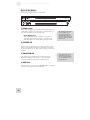
A Tour of the iMultiMix16 USB
Rear of the Mixer
Here’s what you’ll find at the rear of the mixer.
1
2
3
4
1) Power Input
Here’s where you plug in your mixer’s external power supply. You
should always connect your power supply to the mixer before you
plug the power supply into an electrical outlet.
Power Supply Unit:
This unit provides 18VAC at 1200mA x2 of power. As
with nearly all power supply units, this one tends to get
warm when left on for a while. This is perfectly normal.
The POWER INPUT is built
to accept only the power
supply unit provided with
your iMultiMix USB, or an
AC power supply that has the
same specs. Others probably
will not work.
2) POWER ON
Another easy one. Switch this one on and your mixer has power.
Switch it off and it doesn’t. Make sure the faders in the master
section are pulled all the way down when powering your mixer up
or down.
3) PHANTOM ON
This switch activates and deactivates the phantom power
described in “Mic Inputs (Channels 1 – 8),” page 13. This
switch controls phantom power for all four mic inputs.
4) USB Port
This port allows you to connect the iMultiMix USB to a computer
for 2-way, stereo digital audio communication.
22
As we said earlier, it’s very
important that you plug in
your microphones and mute
your system before you turn
on phantom power.
3 Digital Effects Processor
Onboard your iMultiMix USB is a powerful effects unit that has
100 preset programs. We offer a few tips on where to use these,
but don’t limit yourself to our suggestions. We recommend that
you experiment with these effects to get a good feel for how they
can improve your mixes.
Effects Section Components
1) Program Selection Knob
3
4
2
1
You can use this knob to assign one of 100 effect programs to
your mix. Turning the knob to the right increments the program
number, and turning it to the left decrements the program number.
You can control the level of the effect for each channel via the
channel’s AUX B knob. You must PRESS the effect knob to
activate the selected effect.
2) PROGRAM LED Display
This display shows you the number of the current program.
3) CLIP Indicator
When lit, this LED tells you that there is a signal clip at the
internal effects input. This means that you should reduce the signal
via the EFFECTS / AUX RET B LEVEL control.
4) SIG Indicator
You cannot use the A
on-board effects at th
When lit, this LED indicates that the effects processor is receiving
a signal.
Effect Descriptions
HALL
This type of reverb simulates the ambience of a grand concert hall.
ROOM
This type of reverb reproduces the more intimate ambiance of
natural room acoustics.
PLATE
These are simulations of metal plate reverbs, as used on classic
recordings from the '70s and '80s.
CHAMBER
These are simulations of the reverb created by artificial echo
chambers, as used on classic recordings of the '50s and '60s.
23
3
Digital Effects Processor
CHORUS
These create the effect of multiple voices (or instruments)
sounding at once from a single input.
FLANGE
These create a sweeping, swooshing sound effect that you will
probably recognize.
DELAY
These effects are based on a discreet repetition or echo of the
input.
PITCH
These effects transpose the pitch of the input signal and blend the
effect signal with the original to create harmonies.
MULTI & MULTI 2
These are combinations of two or more of the above effects.
24
4 Applications
Your iMultiMix USB can be used in a wide variety of ways in both
live and recording applications. You have several options for
bringing sound into and out of the board. And when it’s brought
in, you can route it to various parts of the mixer for certain desired
effects, or even send it to an external processor or tape deck and
back. To give you some ideas for different mixing scenarios, here
are descriptions of a few common applications for the iMultiMix
USB.
Simple Recording Setup
In this setup, you connect your instruments and microphones to
the mono and stereo channels, making sure to properly set the
level of each channel. You connect your recorder (for example, a
4-track, HD24, or a tape deck) via the 2-TRACK OUT jack. If you
want to output more than two tracks, use the ALT 3/4 OUT. Just
remember to activate the MUTE / ALT 3/4 switch for each
channel you want to feed into the ALT 3/4 OUT.
You can also connect the DIGITAL OUT to a Masterlink or other
stereo recording device with an S/PDIF digital input for a crystal
clear mixdown.
Be sure to use proper cables
when connecting instruments
and other equipment to the
iMultiMix USB. The
guidelines on page 11 will
help.
You can select one on-board effect and control its level with the
AUX B knob for each channel. Or you can use an external effects
processor by sending a signal to the external unit via the AUX
SEND A and returning it via AUX RETURN A (you’ll probably
want to set AUX SEND A to POST, for “post-fader.”). For
monitoring you can connect the CTRL RM OUT jacks to a
speaker or headphone amplifier, or just simply plug headphones
into the PHONES jack.
Recording to iPod
The iMultiMix USB allows you to record your mix directly to an
iPod. This means that anything routed to your Main Mix, such as
instruments, microphones, and even audio from your computer
can be recorded and played back instantly from your iPod. Note
that the iPod will record your Main Mix as a stereo file so it is
important to get your levels right before recording. To ensure that
your recording is clean and pristine, here are some suggestions:
Take some time to balance the levels of your sources.
Use the built-in Limiter feature, ensuring that your recording
does not clip or distort. However, be careful when using the
Limiter – if you are pushing your levels too hard, the Limiter
can cause unwanted audio artifacts. There is a fine line
between a good, loud recording, and a recording which is
overly limited, resulting in poor dynamic range and clarity.
Periodically, check how the recording will sound by pressing
the iPOD TO CTRL RM button into the “down” position.
Your recordings will be
stored as “voice memo” files
on your iPod.
Once you have finished
recording a “memo,” it will
be placed in Main Menu >
Extras > Voice Memos.
After you connect to your
computer and transmit the
voice memos, they can be
located in Main Menu >
Music > Playlists > Voice
Memos.
25
4
Applications
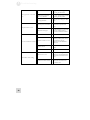
It is also important to understand that not all iPods are created
equal and different models have different capabilities. Please refer
to the following compatibility table to check whether your iPod is
recording-compatible.
iPod Model
iPod
Classic*
5th generation
4th generation**
3rd generation**
2nd generation***
1st generation***
iPod nano
3rd generation*
2nd generation
1st generation
iPod shuffle
iPod mini
iPod touch
Playback
Record
* Limited transport control only
rd
** Transport control only. Charging not possible on 3 generation iPod.
*** Playback through headphone output. No transport control.
Simple Live Setup
This is similar to the recording setup. In a live setup, you most
likely will connect the MAIN MIX OUT to a PA system amplifier
and the CTRL RM OUT to a headphone amplifier for monitoring
purposes. You could also connect a digital equalizer (like the Alesis
DEQ-230D) between the DIGITAL OUT and a PA system for
extra tone control. Try connecting an external effects processor to
the iMultiMix’s send and receive. Your headphones will allow you
to audition a channel before you bring it into the mix, making sure
the levels are OK before the audience hears it.
Using Additional External Audio
Sources
The iMultiMix USB gives you 16 audio inputs in all. If you want to
bring external audio sources into a recording or live mix, you can
do it in several different ways. Using the 2-TRACK IN, you can
add a tape deck, ADAT, CD player or other source to the mix. The
2-TRACK IN also can be used to entertain the audience with a
CD as the band is setting up for a live show. The AUX RETURNS
can be used as additional audio inputs when you are not using
them for effects.
Digital Output to a Digital Recorder
Connect the S/PDIF DIGITAL OUT of your iMultiMix USB
console to the DIGITAL IN on your external digital recorder.
(12-channel and 16-channel models only)
26
Out of the box, your iPod is
formatted to work with a
Mac, rather than a Windows
computer. If you want to
transfer your recordings to a
Windows computer, connect
your iPod to your Windows
computer and allow iTunes to
format it BEFORE you
record for the first time.
If you record to your iPod
before you ever connect it to
iTunes, your recordings will
be stored in Mac’s HFS
format. They will only be
readable by plugging your
iPod into a Mac, not a
Windows computer.
Note that, if you reformat
your iPod for the Windows or
Mac platform, you may lose
any recordings prior to this.
Applications
4
Using the iMultiMix16 USB with a
Computer
Your Alesis iMultiMix mixer comes with a Full Speed USB 1.1
port which you can connect to a computer. This USB connection
allows you to send CD-quality (stereo, 16-bit, 44.1 kHz) audio
between the computer and your iMultiMix mixer.
This feature allows you to use the iMultiMix USB as a highly
flexible external soundcard. Use the computer’s built in audio
recorder—or use dedicated Digital Audio Workstation software—
to record and play back CD-quality audio within your computer.
A 2-meter USB cable is included. If you need to connect the
iMultiMix USB across a longer distance, we recommend that you
purchase a longer USB cable, as using hubs and other extenders
with USB audio often causes glitches and other problems.
Sending and Receiving Audio Data
The USB port sends the iMultiMix USB’s MAIN OUT/TAPE
OUT left and right signals to the computer.
The USB port receives a stereo audio stream from the computer
and assigns it to the TAPE IN left and right channels of your
iMultiMix USB mixer. Note that, if a device is connected to the
iMultiMix USB’s TAPE IN inputs, the signal from this device is
merged with the signal from the computer.
Precautions when using the USB
connection
To ensure that the iMultiMix USB is recognized correctly by your
computer, always turn the iMultiMix USB on a few seconds before
inserting the USB cable into the computer. When powering up
both your computer and the iMultiMix USB, turn on the iMultiMix
USB first and the computer second. When powering down your
computer and the iMultiMix USB, turn off the computer first.
Wait to turn off the iMultiMix USB until the computer has shut
down.
Connection instructions for Windows (XP,
2000, ME, and 98 Second Edition)
Upon first sensing the iMultiMix USB’s USB input, Windows XP
and Windows 2000 automatically recognize the iMultiMix USB
and proceed to install “USB audio codec” drivers. Windows ME
and Windows 98 Second Edition may require you to insert your
Windows disc, after which the drivers should load correctly.
After the iMultiMix USB has been recognized and its drivers have
been installed, open the Control Panel. Select Sounds and Audio
27
4
Applications
Devices (or Multimedia), go to the Audio tab, and select the “USB
audio codec” as your default sound recording and sound playback
device.
Connection instructions for Macintosh (OS
X only)
After plugging in the iMultiMix USB, select “USB Audio
CODEC” in the Sound area of System Preferences. No other
action is required.
The iMultiMix16 USB is not designed for use with Mac OS9 and
below.
28
5 Troubleshooting
If you’re having problems operating the iMultiMix16 USB, this
troubleshooting index will help you correct them.
Symptoms
No sound from the mixer.
Audio signal is distorted.
Cause
Solution
Mixer is not plugged in or turned
on.
Plug in mixer and turn it on.
Faders are too low.
Raise appropriate faders.
Control room level is turned
down
Turn up control room level.
The appropriate signal hasn’t
been assigned to the control
room out.
In the master section of the mixer,
be sure the right switch is selected
(MIX, ALT 3/4 or 2TK)
Cable is not plugged into output
jack.
Check outputs to make sure cables
are plugged in securely.
Headphones are not plugged
into PHONE jack.
Plug headphones into PHONE
jack.
Monitor or headphone amplifier
is turned off or down.
Turn amplifier on or up.
Bad cable.
Check all cables; substitute cables
with known good ones.
Channel level is too high.
Set channel levels using the
procedure on page 12.
Channel input is too high.
Turn down your instrument to a
normal volume and then set channel
levels using procedure on page 12.
AUX RET B level is too high.
Lower the level of AUX RET B in
the master section of the mixer.
MAIN MIX level is too high.
Lower the MAIN MIX fader in the
master section of the mixer.
ALT 3/4 level is too high.
Lower the ALT 3/4 fader in the
master section.
29
5
Troubleshooting
Audio signal carries an unwanted
hum.
Too much low-level noise in the
mix.
Engage the channel’s high-pass filter
by pressing the HPF switch.
Interference from appliances
such as air conditioners.
Engage the channel’s high-pass filter
by pressing the HPF switch.
Not using TRS cables.
Make sure you are using 1/4” TRS
cables.
Phantom power is not turned
on.
Turn on phantom power using the
switch on the rear panel of the
mixer.
Microphone is damaged.
Test the microphone on other audio
devices. If you detect damage,
contact the manufacturer or dealer.
Fader is too low.
Raise channel fader.
Instrument volume is too low.
Turn up the instrument’s volume
control. If problem persists, check
the instrument by plugging
headphones into the instrument’s
phone jack.
Channel is muted.
Check the MUTE / ALT 3/4
switch.
Gain is too low.
Adjust the channel’s GAIN control.
Effects level is too low.
Turn up the level using the
EFFECTS / AUX RET B LEVEL
control in the master section of the
mixer.
An effect hasn’t been selected.
Press the EFFECTS knob on the
desired effect and make sure the
SIG indicator is lit.
Microphone level is too low.
No or low sound from a channel.
Internal effects aren’t working.
30
Troubleshooting
Effects processor is not plugged
in or turned on.
Make sure unit is plugged in and
turned on.
Aux outputs of mixer aren’t
connected to inputs of processor
or processor’s outputs aren’t
connected to mixer’s inputs.
Make sure the mixer’s aux outputs
are connected to the processor’s
inputs and that the processor’s
outputs are connected to the mixer’s
aux inputs.
Mixer’s effects return signal is
too low.
Turn up the output of the effects
processor or turn up the mixer’s
AUX RET A RETURN or
EFFECTS / AUX RET B
RETURN in the master section.
Nothing is routed to the
HDPH/CTRL RM output.
Press the desired MIX, ALT ¾ or 2
TK button.
Computer does not see the
iMultiMix USB.
USB connection must be
established.
Unplug the USB cable and turn off
the iMultiMix USB. Turn the
iMultiMix USB back on and plug
the cable back in. If this does not
work, leave the iMultiMix USB on,
turn off the computer (do not use
“restart” but instead actually turn off
the computer) and then turn it on
again.
Computer sees the iMultiMix
USB, but no sound is received
and/or transmitted.
iMultiMix USB is not set as
primary sound device.
In the computer’s Control Panel, go
to the Sounds/Multimedia area. In
the Audio section, set the default
sound recording and playback
devices to “USB audio codec.”
External effects aren’t working.
LED meters not working.
USB hub may be in use.
USB audio has crackling or
glitches, or audio plays/records at
incorrect pitch.
.
Computer configuration may be
incompatible with USB audio
No power.
Incorrect or defective power
supply.
5
If you are using a USB hub,
disconnect the iMultiMix USB
from it and connect the mixer to the
computer directly instead. Certain
USB chipsets have design limitations
or IRQ assignment restrictions that
must be resolved before audio can
work correctly on them. See your
USB chipset documentation for
further information if required.
Replace with correct power supply
(only use Alesis-recommended AC
output power supply).
31
5
Troubleshooting
This page intentionally left blank.
32
6 Specifications
For the more technical-minded, here are some detailed specifications for the
iMultiMix16 USB’s operating levels.
Input Channels
Mic In Sensitivity Range:
Line In Sensitivity Range:
Mic/Line Gain Range:
-60dBu to –10dBu nominal, +5dBu maximum
-40dBu to -+10dBu nominal, +25dBu maximum
+10 to +60dB
Equalization
High-Pass Filter:
High Shelving:
Mid Bandpass/Band Reject:
Low Shelving:
75Hz, 18dB/octave
12kHz, +/- 15dB
2.5 kHz, +/- 15dB
80Hz, +/- 15dB
Aux Sends
Aux Send A & B Gain Range:
-∞ to +10dB
Aux Returns
Aux Return A Gain Range:
Effects Level/
Aux Return B Gain Range:
-∞ to +15dB
Channel Levels
Channel Level Gain Range:
-∞ to +10dB
Master Levels
Main Mix, Ctrl Room Gain
Range:
-∞ to +10dB
1/4” Inputs
Stereo Aux Return Level:
+4dBu nominal, +20dBu maximum
RCA Inputs
Tape In Level:
-10dBV nominal, +5dBV maximum
1/4” Outputs
Main Mix, Ctrl Room,
Aux 3/4, Ext Aux
Send Level:
+4dBu nominal, +20dBu maximum
Headphone Output
-∞ to +15dB
75 ohm output impedance
>105mW into 75 ohms, >40mW into
600ohms
RCA Outputs
Tape Out Level:
-10dBV nominal, +5dBV maximum
USB Connection
USB 1.1 connection to computer
iPod Recording
Quality
Recording Time
All measurements done
over a 22Hz – 22kHz
range with a 1kHz sine
wave at +18dBu (-1dBFS)
input. Impedances are
measured at 1kHz.
44.1kHz, 16-bit stereo at 1411kbps
30GB: 2 hours, 55 minutes
60GB: 4 hours, 30 minutes
Dimensions (W x L x H)
13.0” x 19.0” x 3.25”
331mm x 483mm x 83mm
Weight
15.0 lbs / 6.8 kg (with adapter)
12.0 lbs / 5.6 kg (without adapter)
33
6
Specifications
This page intentionally left blank.
34
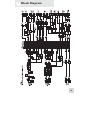
7 Block Diagram
35
7
Block Diagrams
This page intentionally left blank.
36
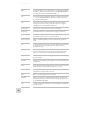
Glossary
Here are the definitions to some terms you’ll probably encounter
while using your iMultiMix16 USB.
Term
Definition
aux (auxiliary)
An additional set of outputs and inputs found on many mixers. These
allow the addition of external effects and other audio sources.
balance
A control that lets you control the position of sound in a stereo signal by
altering the relative levels of the left and right channels.
bus
The electrical component that carries signals from multiple sources to a
single destination such as an amplifier.
channel
A path through which an audio signal flows.
channel strip
A section of a mixer on which reside controls like a fader, EQ and pan
for manipulating the signal of an input channel.
clipping
The cutting of an audio signal caused by a level that is too great for a
mixer circuit to handle.
codec
Compression/decompression algorithm. Different CODECs are used
by different digital audio devices and file formats.
condenser
microphone
A type of high-quality microphone that produces a weak signal, usually
requiring an external power source like the ones provided by your
iMultiMix’s XLR mic inputs.
dB (decibel)
A common unit of measure for audio.
detent
A point of resistance in the path that a mixer knob or fader travels.
Detents are used to mark important settings. As you turn the knob or
slide the fader, you’ll feel it “click” into the detent.
dry
An audio signal free of effects. The opposite of “wet.”
dynamic
microphone
A common type of microphone that does not require external power.
Dynamic microphones are generally cheaper than condenser
microphones.
effects processor
A unit whose purpose is to provide effects for audio signals. Some
common effects include reverb, chorus, flange and delay. Effects
processors come in many shapes and sizes, from small pedals up to
rectangular rackmount units.
EQ (equalizer)
The part of your mixer (or other device) that manipulates an audio signal
by lowering the level of some frequencies and increasing the levels of
others. EQ is used to fine-tune a signal’s highs and lows.
37
Glossary
38
fader
A device that allows you to control the level of an audio signal by sliding
the fader up and down. Each input channel of the iMultiMix USB has its
own fader, and so do the MAIN MIX and ALT 3/4.
gain
The measure of extra amplification applied to an audio signal. Channels
1 – 4 on your iMultiMix USB have gain controls, which are useful for
boosting mic and line signals.
level
The amount of power driving an audio signal. The most common
names given to levels of varying voltage are, from lowest to highest,
microphone level, instrument level and line level.
master section
The section of a mixer where the main mix is controlled.
mic preamp
An amplifier that boosts a microphone-level signal up to line level.
mixer
A device whose purpose is to combine and output a number of audio
signals, allowing various types of signal manipulation.
mono (monaural)
Refers to an audio signal that has only one channel. The opposite of
stereo.
pan
A control that lets you position a mono signal within the stereo spectrum
by altering the level of the signal being sent to the left channel as
opposed to the right.
phantom power
A way of providing power to condenser microphones. Called
“phantom” because the power isn’t apparent to dynamic microphones
when you connect them to an input that provides phantom power.
post-fader
Describes an aux send that sends a signal that already has passed through
the channel fader.
pre-fader
Describes an aux send that sends a signal that has not passed through the
channel fader.
return
A line input that carries an audio signal that has been sent from the mixer
back to the mixer. Usually used in the application of effects.
send
A line output whose function is to send a signal from the mixer to an
external device, usually an effects processor.
stereo
Refers to an audio signal that has two channels.
unity gain
Refers to the setting of an audio channel at which the signal leaves the
channel at the same level at which it entered. Unity gain is marked by a 0
on the iMultiMix USB’s faders.
wet
An audio signal that has had effects or other manipulations applied. The
opposite of “dry.”
Warranty / Contact
Alesis Limited Warranty
ALESIS CORPORATION ("ALESIS") warrants this product to be free of defects
in material and workmanship for a period of one (1) year for parts and for a period of
one (1) year for labor from the date of original retail purchase. This warranty is
enforceable only by the original retail purchaser and cannot be transferred or assigned.
For the most effective service, the purchaser should register the purchase on the
ALESIS website at http://www.alesis.com/account/productregistration.php.
During the warranty period ALESIS shall, at its sole and absolute option, either repair
or replace free of charge any product that proves to be defective on inspection by
ALESIS or its authorized service representative. In all cases disputes concerning this
warranty shall be resolved as prescribed by law.
To obtain warranty service, the purchaser must first call or write ALESIS at the
address and telephone number available on the Alesis Website to obtain a Return
Authorization Number and instructions concerning where to return the unit for
service. All inquiries must be accompanied by a description of the problem. All
authorized returns must be sent to ALESIS or an authorized ALESIS repair facility
postage prepaid, insured and properly packaged. Proof of purchase must be
presented in the form of a bill of sale, canceled check or some other positive proof
that the product is within the warranty period. ALESIS reserves the right to update
any unit returned for repair. ALESIS reserves the right to change or improve design
of the product at any time without prior notice.
For more effective
service and product
update notices, please
register your
iMultiMix online at:
http://www.alesis.com/
account/productregistration
.php
This warranty does not cover claims for damage due to abuse, neglect, alteration or
attempted repair by unauthorized personnel, and is limited to failures arising during
normal use that are due to defects in material or workmanship in the product.
THE ABOVE WARRANTIES ARE IN LIEU OF ANY OTHER
WARRANTIES OR REPRESENTATIONS WHETHER EXPRESS OR
IMPLIED OR OTHERWISE, WITH RESPECT TO THE PRODUCT, AND
SPECIFICALLY EXCLUDE ANY IMPLIED WARRANTIES OF FITNESS
FOR A PARTICULAR PURPOSE OR MERCHANTABILITY OR OTHER
IMPLIED WARRANTIES. Some states do not allow limitations on how long an
implied warranty lasts, so the above limitation may not apply to you.
IN NO EVENT WILL ALESIS BE LIABLE FOR INCIDENTAL,
CONSEQUENTIAL, INDIRECT OR OTHER DAMAGES RESULTING
FROM THE BREACH OF ANY EXPRESS OR IMPLIED WARRANTY,
INCLUDING, AMONG OTHER THINGS, DAMAGE TO PROPERTY,
DAMAGE BASED ON INCONVENIENCE OR ON LOSS OF USE OF THE
PRODUCT, AND, TO THE EXTENT PERMITTED BY LAW, DAMAGES
FOR PERSONAL INJURY. Some states do not allow the exclusion or limitation of
incidental or consequential damages, so the above limitation or exclusion may not
apply to you.
THIS CONTRACT SHALL BE GOVERNED BY THE INTERNAL LAWS OF
THE STATE OF CALIFORNIA WITHOUT REFERENCE TO CONFLICTS
OF LAWS. This warranty gives you specific legal rights, and you may also have other
rights required by law which vary from state to state.
This warranty only applies to products sold to purchasers in the United States of
America or Canada. The terms of this warranty and any obligations of Alesis under
this warranty shall apply only within the country of sale. Without limiting the
foregoing, repairs under this warranty shall be made only by a duly authorized Alesis
service representative in the country of sale. For warranty information in all other
countries please refer to your local distributor.
39
Warranty/Contact
c
Alesis Contact Information
Alesis Distribution, LLC
Los Angeles, CA USA
E-mail:
Web site:
[email protected]
http://www.alesis.com
iMultiMix16 USB Reference Manual
Copyright 2008, Alesis Distribution, LLC. All rights reserved
Reproduction in whole or in part is prohibited. “iMultiMix” and
“iMultiMix16 USB” are trademarks of Alesis, LLC. Specifications
subject to change without notice.
7-51-0256-A
06/19/2008
7-51-0256-A
40