1
Reference Manual
This page intentionally left blank
10%
20%
30%
40%
50%
60%
70%
80%
90%
100%
Table Of Contents
Introduction.....................................................................3
Welcome!...................................................................................................... 3
About the MultiMix-8FX ................................................................4
MultiMix-8FX Key Features ..................................................................... 4
How to Use This Manual.................................................................5
A Few Words for Beginners ...........................................................6
Important Safety Instructions........................................7
Important Safety Instructions (English)........................................7
Safety symbols used in this product......................................................... 7
Please follow these precautions when using this product:.................... 7
Instructions de Sécurité Importantes (French) .............................9
Symboles utilisés dans ce produit............................................................. 9
Veuillez suivre ces précautions lors de l’utilisation de
l’appareil: ...................................................................................................... 9
Lesen Sie bitte die folgende Sicherheitshinweise
(German)..........................................................................................11
Sicherheit Symbole verwendet in diesem Produkt................................. 11
Folgen Sie bitte diesen Vorkehrungen, wenn dieses
Produkt verwendet wird: ........................................................................... 11
CE Declaration Of Conformity ......................................................13
FCC Compliance Statement ...........................................................13
Chapter 1: Getting Started.............................................15
Hooking up the MultiMix-8FX.......................................................15
Using Proper Cables........................................................................15
Setting Levels ...................................................................................16
Chapter Two: A Tour of the MultiMix..........................17
Patchbay...........................................................................................17
Mic Inputs (Channels 1 – 4)...................................................................... 17
Line Inputs (Channels 1 – 4)..................................................................... 17
Line Inputs (Channels 5 – 8)..................................................................... 18
PHONE Jack............................................................................................... 18
AUX RETURNS ........................................................................................ 18
AUX SENDS .............................................................................................. 18
2-TRACK..................................................................................................... 18
MAIN MIX OUT....................................................................................... 18
CTRL RM OUT ......................................................................................... 18
Channel Strips .................................................................................19
Level Control............................................................................................... 19
PAN or BAL................................................................................................ 19
PEAK LED................................................................................................. 19
Aux................................................................................................................ 19
EQ................................................................................................................. 20
Master Section .................................................................................20
Main Mix ...................................................................................................... 20
2TK To Mix................................................................................................. 20
1
Table Of Contents
HDPH / CTRL RM................................................................................... 20
2TK TO CTRL ROOM Switch ............................................................... 21
AUX RETURN A LEVEL....................................................................... 21
EFFECTS / AUX RET B LEVEL ......................................................... 21
LED Meters................................................................................................. 21
POWER Indicator ...................................................................................... 21
+48V Indicator ........................................................................................... 21
Rear of the Mixer ............................................................................21
Power Input ................................................................................................. 21
Power Supply Unit...................................................................................... 22
Power On ..................................................................................................... 22
Phantom On................................................................................................ 22
Chapter Three: Digital Effects Processor .....................23
Effects Section Components ...........................................................23
Program Selection Knob ........................................................................... 23
LED Display................................................................................................ 23
CLIP Indicator ............................................................................................ 23
SIG Indicator .............................................................................................. 23
Effect Descriptions ..........................................................................23
HALL ........................................................................................................... 23
ROOM ......................................................................................................... 23
PLATE ......................................................................................................... 23
CHAMBER ................................................................................................. 23
CHORUS ..................................................................................................... 24
FLANGE..................................................................................................... 24
DELAY ........................................................................................................ 24
PITCH.......................................................................................................... 24
MULTI & MULTI II.................................................................................. 24
Chapter Four: Applications ...........................................25
Simple Recording Setup..................................................................25
Simple Live Setup............................................................................25
Using Additional External Audio Sources.....................................25
Importing Music Into Your Computer..........................................25
Chapter Five: Troubleshooting ......................................27
Chapter Six: Specifications ............................................31
Chapter Seven: Block Diagram .....................................33
Glossary ...........................................................................35
Warranty/Contact Alesis ................................................37
Alesis Limited Warranty............................................................................. 37
Alesis Contact Information....................................................................... 38
2
Introduction
Welcome!
Thank you for making the Alesis MultiMix-8FX a part of your
studio. Since 1984, we've been designing and building creative
tools for the audio community. We believe in our products,
because we've heard the results that creative people like you have
achieved with them. One of Alesis' goals is to make high-quality
studio equipment available to everyone, and this Reference Manual
is an important part of that. After all, there's no point in making
equipment with all kinds of capabilities if no one explains how to
use them. So, we try to write our manuals as carefully as we build
our products.
For more effective
service and product
update notices, please
register your
MultiMix-8FX online
at:
http://www.alesis.com/
support/warranty.htm
The goal of this manual is to get you the information you need as
quickly as possible, with a minimum of hassle. We hope we've
achieved that. If not, please drop us an email and give us your
suggestions on how we could improve future editions of this
manual.
We hope your investment will bring you many years of creative
enjoyment and help you achieve your musical goals.
Sincerely,
The people of Alesis
3
Introduction
About the MultiMix-8FX
The MultiMix-8FX is the latest in the large family of Alesis audio
mixers. We’ve come a long way since the 1622 mixer we first built
in 1989. Since that time audio technology has grown in leaps and
bounds, pushing up quality and driving down prices. Only a few
years ago, you wouldn’t have been able to buy a mixer this
powerful for such an affordable price. Just take a look at the key
features listed below, and you’ll see that you have just made an
incredible addition to your home studio or live setup.
The MultiMix-8FX gives you just about everything you need to
create polished, professional-sounding mixes When designing this
unit, our goal was to give you as much control over your mixes as
possible without requiring a wealth of extra equipment. That’s why
we added tools like the digital effects processor and the mic
preamps. And with a multitude of ways in which to connect other
equipment and instruments, the MultiMix-8FX offers endless
possibilities.
MultiMix-8FX Key Features
y
y
y
y
y
y
y
y
y
4
4 microphone/line inputs with up to 50dB of preamp
gain – gives a boost to microphones and instruments with
weak levels.
2 stereo line inputs – great for line-level instruments
Internal digital effects processor with 100 preset effects
and an easy-to-read display – includes a variety of reverbs,
delays, choruses, flanges, a pitch transposer and combinations
of these.
3-band EQ per channel – a potent tool for sonically
shaping each channel to get that perfect mix.
1 pre-fader aux send per channel – gives you control over
the level of the pre-fader signal being routed to an external
device.
1 post-fader aux send/effects send per channel – a
control for the signal being routed to another external device
or to the onboard effects processor.
Control room output level – provides control over the
separate control room output
2-track send and return – lets you mix your audio to tape or
other media and to add a tape deck or CD player to the mix
External power supply
Introduction
How to Use This Manual
This manual is divided into the following sections describing the
various functions and applications for the MultiMix-8FX. While
it's a good idea to read through the entire manual once carefully,
those having general knowledge about mixing should use the table
of contents to look up specific functions.
Chapter 1: Getting Started shows you how to include the MultiMix8FX in your audio setup for recording and live applications. We’ve
included a hookup diagram, guidelines for which cables to use and
the vital steps you must take to set levels properly.
Helpful tips and advice are
highlighted in a shaded box
like this.
Chapter 2: A Tour of the MultiMix describes the MultiMix-8FX piece
by piece. This chapter also features diagrams of the mixer to help
you find each component as you read about it.
Chapter 3: Digital Effects Processor explains the effects provided by
the on-board digital effects processor. If you want to know what a
certain effect will do to your sound before you select it, this is
where you should look.
Chapter 4: Applications outlines a number of scenarios in which
you can use the MultiMix-8FX, including some tips on what
goes where when you’re hooking everything up.
Chapter 5: Troubleshooting can give you a hand if you’re experiencing
problems with your mixer. You’ll find that most issues can be
resolved simply and quickly with the push of a button.
When something important
appears in the manual, an
exclamation mark (like the
one shown at left) will appear
with some explanatory text.
This symbol indicates that
this information is vital when
operating the MultiMix-8FX.
Chapter 6: Specifications and Chapter 7: Block Diagram are full of
technical information for the more advanced users.
And at the end of this manual you’ll see a glossary of common
mixing-related terms and a page about the MultiMix-8FX’s
warranty.
5
Introduction
A Few Words for Beginners
We realize that some of you who have purchased the MultiMix8FX are fairly new to the art of mixing, and we’ve written this
manual with that in mind. We also designed the MultiMix-8FX to
be both powerful and easy enough to use that even a beginner can
quickly pick up the basics.
Many mixer manuals—and manuals for just about any electronic
instrument for that matter—are full of complicated terminology
and incomplete instructions that presume a lot of experience on
the part of the reader. We try to avoid that with this manual. True
enough, you will find all the technical lingo and specifications you
can handle in here, but we do our best to make this accessible to
you.
Beginners will find several elements of this manual especially
useful. Keep your eye out for the tips found in the gray boxes on
the right side of the page. Be sure to check out the hookup
diagrams on page 15, which will give you some ideas on how to fit
the mixer into your audio setup after you’ve taken a tour of the
mixer in Chapter 2. And if you come across any terms that you
haven’t seen before, the glossary probably can help you out.
6
One of the most important
things you’ll do before you
begin a mixing session is to
set the levels. Be sure to refer
to the instructions on page
16.
Important Safety
Instructions
Important Safety Instructions (English)
Safety symbols used in this product
This symbol alerts the user that there are important
operating and maintenance instructions in the literature
accompanying this unit.
This symbol warns the user of uninsulated voltage within
the unit that can cause dangerous electric shocks.
This symbol warns the user that output connectors contain
voltages that can cause dangerous electrical shock.
Please follow these precautions when using this
product:
1.
2.
3.
4.
5.
6.
7.
8.
9.
10.
11.
Read these instructions.
Keep these instructions.
Heed all warnings.
Follow all instructions.
Do not use this apparatus near water.
Clean only with a damp cloth. Do not spray any liquid cleaner
onto the faceplate, as this may damage the front panel controls
or cause a dangerous condition.
Install in accordance with the manufacturer's instructions.
Do not install near any heat sources such as radiators, heat
registers, stoves, or other apparatus (including amplifiers) that
produce heat.
Do not defeat the safety purpose of the polarized or
grounding-type plug. A polarized plug has two blades with
one wider than the other. A grounding-type plug has two
blades and a third grounding prong. The wide blade or the
third prong is provided for your safety. When the provided
plug does not fit into your outlet, consult an electrician for
replacement of the obsolete outlet.
Protect the power cord from being walked on or pinched,
particularly at plugs, convenience receptacles, and the point
where they exit from the apparatus.
Use only attachments or accessories specified by the
manufacturer.
Continued next page
7
Important Safety Instructions
12. Use only with a cart, stand, bracket, or table designed for use
with professional audio or music equipment. In any
installation, make sure that injury or damage will not result
from cables pulling on the apparatus and its mounting. If a
cart is used, use caution when moving the cart/apparatus
combination to avoid injury from tip-over.
13. Unplug this apparatus during lightning storms or when unused
for long periods of time.
14. Refer all servicing to qualified service personnel. Servicing is
required when the apparatus has been damaged in any way,
such as when the power-supply cord or plug is damaged, liquid
has been spilled or objects have fallen into the apparatus, the
apparatus has been exposed to rain or moisture, does not
operate normally, or has been dropped.
15. This unit produces heat when operated normally. Operate in a
well-ventilated area with at least six inches of clearance from
peripheral equipment.
16. This product, in combination with an amplifier and
headphones or speakers, may be capable of producing sound
levels that could cause permanent hearing loss. Do not
operate for a long period of time at a high volume level or at a
level that is uncomfortable. If you experience any hearing loss
or ringing in the ears, you should consult an audiologist.
17. Do not expose the apparatus to dripping or splashing. Do not
place objects filled with liquids (flower vases, soft drink cans,
coffee cups) on the apparatus.
18. WARNING: To reduce the risk of fire or electric shock, do
not expose this apparatus to rain or moisture.
8
Important Safety Instructions
Instructions de Sécurité Importantes (French)
Symboles utilisés dans ce produit
Ce symbole alèrte l’utilisateur qu’il existe des instructions
de fonctionnement et de maintenance dans la documentation
jointe avec ce produit.
Ce symbole avertit l’utilisateur de la présence d’une
tension non isolée à l’intérieur de l’appareil pouvant engendrer des
chocs électriques.
Ce symbole prévient l'utilisateur de la présence de tensions
sur les raccordements de sorties, représentant un risque
d'électrocution.
Veuillez suivre ces précautions lors de l’utilisation
de l’appareil:
1.
2.
3.
4.
5.
6.
7.
8.
9.
10.
11.
Lisez ces instructions.
Gardez ces instructions.
Tenez compte de tous les avertissements.
Suivez toutes les instructions.
N’utilisez pas cet allareil à proximité de l’eau.
Ne nettoyez qu’avec un chiffon humide. Il est potentiellement
dangereux d'utiliser des pulvérisateurs ou nettoyants liquides
sur cet appareil.
Installez selon les recommandations du constructeur.
Ne pas installer à proximilé de sources de chaleur comme
radiateurs, cuisinière ou autre appareils (don’t les
amplificateurs) produisant de la chaleur.
Ne pas enlever la prise de terre du cordon secteur. Une prise
murale avec terre deux broches et une troisièrme reliée à la
terre. Cette dernière est présente pour votre sécurité. Si le
cordon secteur ne rentre pas dans la prise de courant,
demandez à un électricien qualifié de remplacer la prise.
Evitez de marcher sur le cordon secteur ou de le pincer, en
particulier au niveau de la prise, et aux endroits où il sor de
l’appareil.
N’utilisez que des accessoires spécifiés par le constructeur.
Suite de la page suivante
9
Important Safety Instructions
12. N’utilisez qu’avec un stand, ou table conçus pour l’utilisation
d’audio professionnel ou instruments de musique. Dans toute
installation, veillez de ne rien endommager à cause de câbles
qui tirent sur des appareils et leur support.
13. Débranchez l’appareil lors d’un orage ou lorsqu’il n’est pas
utilisé pendant longtemps.
14. Faites réparer par un personnel qualifié. Une réparation est
nécessaire lorsque l’appareil a été endommagé de quelque sorte
que ce soit, par exemple losrque le cordon secteur ou la prise
sont endommagés, si du liquide a coulé ou des objets se sont
introduits dans l’appareil, si celui-ci a été exposé à la pluie ou à
l’humidité, ne fonctionne pas normalement ou est tombé.
15. Puisque son fonctionement normale génère de la chaleur,
placez cet appareil au moins 15cm. des équipments
péripheriques et assurez que l’emplacement permet la
circulation de l’air.
16. Ce produit, utilisé avec un amplificateur et un casque ou des
enceintes, est capable de produite des niveaux sonores pouvant
engendrer une perte permanente de l’ouïe. Ne l’utilisez pas
pendant longtemps à un niveau sonore élevé ou à un niveau
non confortable. Si vous remarquez une perte de l’ouïe ou un
bourdonnement dans les oreilles, consultez un spécialiste.
17. N'exposez pas l'appareil à l'égoutture ou à l'éclaboussement.
Ne placez pas les objets remplis de liquides (vases à fleur,
boîtes de boisson non alcoolique, tasses de café) sur l'appareil.
18. AVERTISSEMENT: Pour réduire le risque du feu ou de
décharge électrique, n'exposez pas cet appareil à la pluie ou à
l'humidité.
10
Important Safety Instructions
Lesen Sie bitte die folgende Sicherheitshinweise (German)
Sicherheit Symbole verwendet in diesem Produkt
Dieses Symbol alarmiert den Benutzer, daß es wichtige
Funktionieren und Wartung Anweisungen in der Literatur gibt, die
diese Maßeinheit begleitet.
Dieses Symbol warnt den Benutzer der nicht isolierten
Spannung innerhalb der Maßeinheit, die gefährliche elektrische
Schläge verursachen kann.
Dieses Symbol warnt den Benutzer, dem Ausgabestecker
Spannungen enthalten, die gefährlichen elektrischen Schlag
verursachen können.
Folgen Sie bitte diesen Vorkehrungen, wenn
dieses Produkt verwendet wird:
1.
2.
3.
4.
5.
6.
7.
8.
9.
10.
11.
Lesen Sie die Hinweise.
Halten Sie sich an die Anleitung.
Beachten Sie alle Warnungen.
Beachten Sie alle Hinweise.
Bringen Sie das Gerät nie mit Wasser in Berührung.
Verwenden Sie zur Reinigung nur ein weiches Tuch.
Verwenden Sie keine flüssigen Reinigungsmittel. Dies kann
gefährliche Folgen haben.
Halten Sie sich beim Aufbau des Gerätes an die Angaben des
Herstellers.
Stellen Sie das Gerät nich in der Nähe von Heizkörpern,
Heizungsklappen oder anderen Wärmequellen (einschließlich
Verstärkern) auf.
Verfehlen Sie nicht den Zweck des grounging Terminals auf
dem Netzstecker. Dieses Terminal wird für Ihre Sicherheit zur
Verfügung gestellt.
Verlegen Sie das Netzkabel des Gerätes niemals so, daß man
darüber stolpern kann oder daß es gequetscht wird.
Benutzen Sie nur das vom Hersteller empfohlene Zubehör.
Fortsetzung auf nächster Seite
11
Important Safety Instructions
12. Verwenden Sie ausschließlich Wagen, Ständer, oder Tische, die
speziell für professionelle Audio- und Musikinstrumente
geeignet sind. Achten Sie immer darauf, daß die jeweiligen
Geräte sicher installiert sind, um Schäden und Verletzungen zu
vermeiden. Wenn Sie einen Rollwagen benutzen, achten Sie
darauf, das dieser nicht umkippt, um Verletzungen
auszuschließen.
13. Ziehen Sie während eines Gewitters oder wenn Sie das Gerät
über einen längeren Zeitraum nicht benutzen den Netzstecher
aus der Steckdose.
14. Die Wartung sollte nur durch qualifiziertes Fachpersonal
erfolgen. Die Wartung wird notwendig, wenn das Gerät
beschädigt wurde oder aber das Stromkabel oder der Stecker,
Gegenstände oder Flüssigkeit in das Gerät gelangt sind, das
Gerät dem Regen oder Feuchtigkeit ausgesetzt war und
deshalb nicht mehr normal arbeitet oder heruntergefallen ist.
15. Dieses Gerät produziert auch im normalen Betrieb Wärme.
Achten Sie deshalb auf ausreichende Lüftung mit mindestens
15 cm Abstand von anderen Geräten.
16. Dieses Produkt kann in Verbindung mit einem Verstärker und
Kopfhörern oder Lautsprechern Lautstärkepegel erzeugen, die
anhaltende Gehörschäden verursachen. Betreiben Sie es nicht
über längere Zeit mit hoher Lautstärke oder einem Pegel, der
Ihnen unangenehm is. Wenn Sie ein Nachlassen des Gehörs
oder ein Klingeln in den Ohren feststellen, sollten Sie einen
Ohrenarzt aufsuchen.
17. Setzen Sie den Apparat nicht Bratenfett oder dem Spritzen aus.
Plazieren Sie die Nachrichten, die mit Flüssigkeiten (gefüllt
werden Blumevases, Getränkdosen, Kaffeetassen) nicht auf
den Apparat.
18. WARNING: um die Gefahr des Feuers oder des elektrischen
Schlages zu verringern, setzen Sie diesen Apparat nicht Regen
oder Feuchtigkeit aus.
12
Important Safety Instructions
CE Declaration Of Conformity
See our Web site at:
http://www.alesis.com
FCC Compliance Statement
This device complies with Part 15 of the FCC rules. Operation is
subject to the following two conditions: (1) This device may not
cause harmful interference and (2) this device must accept any
interference received, including interference that may cause
undesired operation.
NOTE: This equipment has been tested and found to comply with
the limits for a Class B digital device, pursuant to Part 15 of the
FCC Rules. These limits are designed to provide reasonable
protection against harmful interference in a residential installation.
This equipment generates, uses and can radiate radio frequency
energy and, if not installed and used in accordance with the
instructions, may cause harmful interference to radio
communications. However, there is no guarantee that interference
will not occur in a particular installation. If this equipment does
cause harmful interference to radio or television reception, which
can be determined by turning the equipment off and on, the user
is encouraged to try to correct the interference by one or more of
the following measures:
-- Reorient or relocate the receiving antenna.
-- Increase the separation between the equipment and receiver.
-- Connect the equipment into an outlet on a circuit different from
that to which the receiver is connected.
-- Consult the dealer or an experienced radio/TV technician for
help.
13
Important Safety Instructions
This page intentionally left blank
14
1 Getting Started
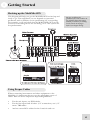
Hooking up the MultiMix-8FX
This diagram will help you get the MultiMix-8FX hooked up and
ready to go. The equipment you use depends on personal
preference and on whether you’re performing live or recording.
For example, you’ll see below that the MAIN MIX OUT can be
routed to a recording device for recording, or to a PA system for
live performance.
Be sure to follow the
guidelines for which cables to
use (further down this page)
and the procedure for setting
levels (on the next page)
before you begin mixing.
Using Proper Cables
When connecting instruments and other equipment to the
MultiMix, it’s important that you use the appropriate types of
cables. Here are some simple but important guidelines:
y
y
y
For the mic inputs, use XLR cables.
For the line inputs and all other 1/4” connections, use 1/4”
mono TRS cables.
And use stereo RCA cables for the 2-track in and out.
15
1
Getting Started
Setting Levels
Before you can begin mixing different audio sources with your
MultiMix, you must set the level for each channel you’re using.
This helps to prevent distortion and clipping. The idea is to get the
strongest signal possible without clipping. Here’s how:
1. Turn the channel level control to the 12:00 position.
2. Turn the AUX SEND and GAIN controls all the way down,
and turn the EQ knobs to the center detent (you’ll feel a click).
3. Connect the source of the signal to the channel’s input.
4. Play the instrument at a normal level and adjust the channel’s
gain slowly until the PEAK LED lights.
5. Slowly reduce the channel’s gain until the PEAK LED no
longer lights when you play.
6. If you need to apply EQ, do so and check the PEAK LED to
make sure it still does not light as you play.
16
2 A Tour of the MultiMix
In this chapter, you’ll learn all about the MulitMix-8FX’s
components (except for the digital effects processor, which is
explained in the next chapter). Please refer to the diagrams as you
read each section to see which components we’re talking about.
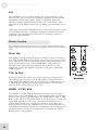
Patchbay
At the rear portion of the top of the MultiMix-8FX, you’ll find the
patchbay. This is where you plug in instruments, signal processors,
multitrack recorders and other devices. Whatever you need to
connect to the mixer, this is where it’s done. In the following
paragraphs, we tell you all about the inputs, outputs, switches and
knobs you see in this section of the mixer.
Mic Inputs (Channels 1 – 4)
The MultiMix uses standard XLR-type mic inputs. These provide
+48V phantom power that you can turn on and off with the
Phantom On switch located on the rear of the mixer. You
probably will have to turn on the phantom power when you’re
using most condenser mics, as these usually require the extra
voltage (unless the mic has its own power source, such as a battery).
Dynamic and ribbon mics don’t require phantom power and are
unaffected when the power is on.
These high-quality mic inputs also feature up to 50dB of preamp
gain that you can adjust with the Gain knob.
Another useful feature of these mic inputs is a high-pass filter
(HPF) that can be turned on and off with the HPF switch. When
you activate this switch, all frequencies below 75Hz are cut from
the signal. This is useful for mic or line signals that don’t have
much bottom end, such as vocals, snares, cymbals and electric
guitar. You’ll want to leave this inactivated for instruments like
basses and kick drums.
Line Inputs (Channels 1 – 4)
The line inputs, marked LINE IN, are balanced 1/4” jacks that
offer the same 50dB of preamp gain and the high-pass filter
provided by the mic inputs (however, phantom power does not
apply to line inputs). These inputs accept line-level instruments
such as keyboards and drum machines. If you find that your
instrument has a weak line signal, just plug it into channels 1 – 4
and crank it up with the Gain knob.
Although chances are your
microphones will work fine
with these mic inputs, we
recommend that you do some
checking up on the type of
microphone you’re using,
especially if it’s one of the
older vintage models. Verify
that your microphone
requires phantom power and
make sure its output is low
impedance, balanced and
floating.
Always connect your
microphones before
activating phantom power.
Microphones tend to be very
sensitive, and the sudden
power surge can do
permanent damage to the
mic’s circuitry. It’s also a
good idea to lower mixer
levels before you activate
phantom power.
17
2
A Tour of the MultiMix
Line Inputs (Channels 5 – 8)
Unlike channels 1 – 4, the line inputs on channels 5 – 8 are stereo
inputs that have left and right inputs. If you’re using one of these
channels as a mono input, plug your instrument into the left input.
Channels 5 – 8 don’t have the extra gain found on channels 1 – 4
because most line-level instruments don’t require the extra boost.
MIDI and other electronic instruments will work especially well on
these channels. These inputs are also good for connecting CD
players or tape decks, as these audio sources don’t require extra
gain.
PHONE Jack
The headphone jack accepts 1/4” jacks. If your headphones are
1/8”, you can find a 1/8” to 1/4” adapter in most electronics
stores.
AUX RETURNS
These are the 1/4” jacks where you connect the outputs of an
external effects processor or other audio source. Each aux return
gives you 15dB of gain that can be controlled by the AUX RET A
and EFFECTS / AUX RET B LEVEL knobs in the mixer’s
output section.
AUX SENDS
And these is the 1/4” jacks where you connect the lines that are
going into the input of an external effects processor. The aux
sends give you 10dB of gain that can be controlled in the AUX
section of each channel input.
2-TRACK
The 2-TRACK IN and OUT jacks are standard RCA jacks. You’ll
use the OUTs for mixing to a tape deck or other recorder. With
the INs you can bring in a signal, which can be monitored and
even added to the main mix via the 2TK TO MIX switch in the
master section of the mixer.
MAIN MIX OUT
These 1/4” jacks are where the signal on the main mix bus leaves
the mixer. From there you can send it to a recorder or a PA system.
The level of this signal is controlled by the MAIN MIX level
control.
CTRL RM OUT
You can use these 1/4" jacks to send the control room signal to
the input of the amplifier driving your monitors or headphones.
This output usually carries the main mix. However, if you engage
the 2TK TO CTRL ROOM switch, the CTRL RM OUT will carry
the signal present at the 2-TRACK inputs.
18
If you are using an effects
device with only a mono
output, plug it into the left
return of STEREO AUX
RETURN. It will appear in
the center of the stereo
spectrum, and not to the left.
A Tour of the MultiMix
2
Channel Strips
The eight channel strips are virtually identical to each other, with
the only difference being that channels 1 – 4 are mono and
channels 5 – 8 are stereo. Each channel strip contains the following
components.
Level Control
The level control knob controls how much of the signal from the
mic or line inputs is sent to the channel. To adjust the level, simply
turn the knob to the desired level. In the leftmost position, levels
are cut completely, and in the rightmost position you get an
additional 10dB of gain.
PAN or BAL
This control—labeled PAN on the mono channels and BAL on
the stereo channels—lets you assign the channel to a particular
spot within the stereo spectrum. If you turn this knob to the left,
you can hear the signal move to the left, and if you turn it to the
right…you get the picture. The pan controls do this by adjusting
the amount of the signal being sent to the left main mix bus versus
the right main mix bus. The balance controls do it by controlling
the relative balance of the left and right channel signals being sent
to the left and right main mix buses.
PEAK LED
This indicator lets you know when the channel’s signal is clipping.
This light plays an important role in setting channel levels by
helping you know when to reduce the channel’s gain.
Aux
Here you’ll find knobs that control the levels of aux sends A and B.
AUX A is pre-fader, which means that the AUX A send is affected
only by the EQ and HPF settings. A pre-fader send is usually used
for cue sends (for example, sending a signal to headphones while
recording, for which you may not want the fader to alter the
channel’s level).
AUX B is post-fader, which means that the AUX B send is
affected by the fader (or level control knob in this instance), EQ
and HPF settings. A post-fader send is generally used for sending
the signal to an external effects device (so that the fader controls
the signal level). Like AUX A, AUX B can be used for routing
signals to external devices. And when you are using the onboard
effects processor, AUX B is used to control the level of the
channel’s signal being routed to the processor.
19
2
A Tour of the MultiMix
EQ
The MultiMix gives you three bands of EQ per channel. Using
these knobs, you can tailor the channel’s signal by boosting some
frequencies and cutting others. The LO and HI controls are
shelving controls with fixed frequencies of 75 Hz and 12 kHz
respectively. The MID control has a peaking response fixed at 2.5
kHz.
“Shelving” means that the mixer boosts or cuts all frequencies past
the specified frequency. “Peaking” means that frequencies above
and below the specified frequency fall off, forming a peak in a
graphical representation.
Master Section
The Master Section is the heart of the mixer, where the channel
inputs and aux returns all are mixed together and routed in various
ways.
Main Mix
The signals from all channels and aux sends are sent to the main
mix. The MAIN MIX level control is the one you’ll use to control
the overall level of those combined signals. This knob affects the
levels of the signals sent to the MAIN MIX OUT and the 2TRACK OUT. In its leftmost position the signal is cut off
completely, and in the rightmost position you get an additional
10dB of gain.
2TK To Mix
When you press this switch, the signal coming in through the 2TRACK IN gets routed to the MAIN MIX, joining whichever
other signals are already part of the main mix. Used this way, the
2-TRACK IN effectively becomes another stereo channel (but
without all the extras like pan, EQ, etc.).
HDPH / CTRL RM
The HDPH / CTRL RM knob controls the level of the signal
being sent to the CTRL RM OUT and the PHONES output. The
level of this signal is represented by the LED meters. The “CTRL
RM” in the name of this knob refers to the fact that it controls the
signal that typically is sent to the control room monitors of a
studio, where someone—usually an engineer—is working the
mixer. However, don’t be intimidated if you’re using this mixer in
your bedroom, which probably isn’t equipped with a control room.
In this scenario, you can use headphones or connect the CTRL
RM OUT to your speakers.
20
A Tour of the MultiMix
2
2TK TO CTRL ROOM Switch
When you engage this switch, the signal coming in from the 2TRACK jacks is routed to the headphones and to the control
room output. This level is controlled by the HDPH / CTRL
ROOM level control and cancels out any signal from the main mix.
AUX RETURN A LEVEL
This is the level control for the signal returning to the mixer via
AUX RETURN A.
EFFECTS / AUX RET B LEVEL
If you are using one of the MultiMix-8FX’s internal effects, this
knob controls the effect level. If AUX SEND B is connected to an
external device, this knob controls the level for AUX RETURN B.
LED Meters
These are the two rows of yellow, green and red lights you see in
the master section of the mixer. The LED meters allow you to
view the signal level of the main mix and 2-TRACK IN depending
on which signal you have routed to the control room mix.
POWER Indicator
When this LED is lit up, that means the POWER ON switch on
the rear of the mixer has been activated.
+48V Indicator
When this one is lit up, that means the PHANTOM ON switch on
the rear of the mixer has been activated and is supplying +48V
phantom power to all XLR mic inputs.
Rear of the Mixer
Here’s what you’ll find at the rear of the mixer.
Power Input
Here’s where you plug in your mixer’s external power supply.
You should always connect your power supply to the mixer before
you plug the power supply into an electrical outlet.
The POWER INPUT is built
to accept only the power
supply unit provided with
your MultiMix-8FX, or an AC
power supply that has the
same specs. Others probably
will not work.
21
2
A Tour of the MultiMix
Power Supply Unit
This unit provides 18.5 VAC at 700 mA, more than enough to
keep your MultiMix-8FX running smoothly. As with nearly all
power supply units, this one tends to get warm when left on for a
while. This is perfectly normal.
Power On
Another easy one. Switch this one on and your mixer has power.
Switch it off and it doesn’t. Make sure that all master output knobs
are turned all the way down when powering your mixer up or
down.
Phantom On
This switch activates and deactivates the phantom power
described in “Mic Inputs (Channels 1 – 4),” page 17. This
switch controls phantom power for all four mic inputs.
22
As we said earlier, it’s very
important that you plug in
your microphones and mute
your system before you turn
on phantom power.
3 Digital Effects Processor
Onboard your MultiMix-8FX™ is a powerful effects
unit that has 100 preset programs. We offer a few tips on
where to use these, but don’t limit yourself to our
suggestions. We recommend that you experiment with
these effects to get a good feel for how they can improve
your mixes.
Effects Section Components
Program Selection Knob
You can use this knob to assign one of 100 effect programs to
your mix. Turning the knob to the right increments the program
number, and turning it to the left decrements the program number.
You can control the level of the effect for each channel via the
channel’s AUX B knob. You must PRESS the effect knob to
activate the selected effect.
LED Display
This display shows you the number of the current program.
CLIP Indicator
When lit, this LED tells you that there is a signal clip at the
internal effects input. This means that you should reduce the signal
via the EFFECTS / AUX RET B LEVEL control.
SIG Indicator
When lit, this LED indicates that the effects processor is receiving
a signal.
Effect Descriptions
HALL
This type of reverb simulates the ambience of a grand concert hall.
ROOM
This type of reverb reproduces the more intimate ambiance of
natural room acoustics.
PLATE
These are simulations of metal plate reverbs, as used on classic
recordings from the '70s and '80s.
CHAMBER
These are simulations of the reverb created by artificial echo
chambers, as used on classic recordings of the '50s and '60s.
23
3
Digital Effects Processor
CHORUS
These create the effect of multiple voices (or instruments)
sounding at once from a single input.
FLANGE
These create a sweeping, swooshing sound effect that you will
probably recognize.
DELAY
These effects are based on a discreet repetition or echo of the
input.
PITCH
These effects transpose the pitch of the input signal and blend the
effect signal with the original to create harmonies.
MULTI & MULTI II
These are combinations of two or more of the above effects.
24
4 Applications
Your MultiMix-8FX can be used in a wide variety of ways in both
live and recording applications. You have several options for
bringing sound into and out of the board. And when it’s brought
in, you can route it to various parts of the mixer for certain desired
effects, or even send it to an external processor or tape deck and
back. To give you some ideas for different mixing scenarios, here
are descriptions of a few common applications for the MultiMix8FX.
Simple Recording Setup
In this setup, you connect your instruments and microphones to
the mono and stereo channels, making sure to properly set the
level of each channel. To record directly from the mixer to a tape
deck or other device, connect the device via the 2-TRACK OUT
jack. To record to a multitrack recorder, connect the MAIN MIX
OUT to the recorder’s inputs.
You can select one on-board effect and control its level with the
AUX B knob for each channel. Or you can use an external effects
processor by sending a signal to the external unit via the AUX
SEND A and returning it via AUX RETURN A.
For monitoring you can connect the CTRL RM OUT jacks to a
speaker or headphone amplifier, or just simply plug headphones
into the PHONES jack.
Simple Live Setup
This is similar to the recording setup. In a live setup, you most
likely will connect the MAIN MIX OUT to a PA system amplifier
and the CTRL RM OUT to a headphone amplifier for monitoring
purposes. Try connecting an external effects processor to the
MultiMix’s send and receive. Your headphones will allow you to
audition a channel before you bring it into the mix, making sure
the levels are OK before the audience hears it.
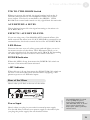
Using Additional External Audio Sources
The MultiMix-8FX gives you 8 audio inputs in all. If you want to
bring external audio sources into a recording or live mix, you can
do it in several different ways. Using the 2-TRACK IN, you can
add a tape deck, ADAT, CD player or other source to the mix. The
2-TRACK IN also can be used to entertain the audience with a
CD as the band is setting up for a live show. The AUX RETURNS
can be used as additional audio inputs when you are not using
them for effects.
Importing Music Into Your Computer
If you would like to import your earlier recordings—or audio from
any other source—into your computer, you can use the MultiMix8FX to ensure the resulting audio file is mixed properly. Just
connect your 4-track, tape deck or other device to the mixer using
the 2-TRACK IN or the mixer’s channel inputs. The MultiMix’s
main output should be connected to an input device that is
25
4
Applications
compatible with your computer, and you’ll need proper recording
software. You can find these in many computer or music stores.
26
5 Troubleshooting
If you’re having problems operating the MultiMix-8FX, this
troubleshooting index will help you correct them.
Symptoms
No sound from the mixer.
Audio signal is distorted.
Audio signal carries an
unwanted hum.
Cause
Solution
Mixer is not plugged in or
turned on.
Plug in mixer and turn it on.
Channel levels are too low.
Turn up channel levels.
Control room level is turned
down
Turn up control room level.
The appropriate signal hasn’t
been assigned to the control
room out.
In the master section of the
mixer, be sure the right switch is
selected.
Cable is not plugged into
output jack.
Check outputs to make sure
cables are plugged in securely.
Headphones are not plugged
into PHONE jack.
Plug headphones into PHONE
jack.
Monitor or headphone
amplifier is turned off or
down.
Turn amplifier on or up.
Bad cable.
Check all cables; substitute
cables with known good ones.
Channel level is too high.
Set channel levels using the
procedure on page 16.
Channel input is too high.
Turn down your instrument to a
normal volume and then set
channel levels using procedure
on page 16.
AUX RET level is too high.
Lower the level of AUX RET A
or B in the master section of the
mixer.
MAIN MIX level is too high.
Turn down the MAIN MIX
level control in the master
section of the mixer.
Too much low-level noise in
the mix.
Engage the channel’s high-pass
filter by pressing the HPF
switch.
Interference from appliances
such as air conditioners.
Engage the channel’s high-pass
filter by pressing the HPF
switch.
27
5
Troubleshooting
Microphone level is too low.
No or low sound from a
channel.
Internal effects aren’t
working.
External effects aren’t
working.
LED meters not working.
28
Not using TRS cables.
Make sure you are using 1/4”
TRS cables.
Phantom power is not
turned on.
Turn on phantom power using
the switch on the rear panel of
the mixer.
Microphone is damaged.
Test the microphone on other
audio devices. If you detect
damage, contact the
manufacturer or dealer.
Channel level is too low.
Turn up channel level.
Instrument volume is too
low.
Turn up the instrument’s
volume control. If problem
persists, check the instrument by
plugging headphones into the
instrument’s phone jack.
Gain is too low.
Adjust the channel’s GAIN
control.
Effects level is too low.
Turn up the level using the
EFFECTS / AUX RET B
LEVEL control in the master
section of the mixer.
An effect hasn’t been
selected.
Press the EFFECTS knob on
the desired effect and make sure
the SIG indicator is lit.
Effects processor is not
plugged in or turned on.
Make sure unit is plugged in and
turned on.
Aux outputs of mixer aren’t
connected to inputs of
processor or processor’s
outputs aren’t connected to
mixer’s inputs.
Make sure the mixer’s aux
outputs are connected to the
processor’s inputs and that the
processor’s outputs are
connected to the mixer’s aux
inputs.
Mixer’s effects return signal is
too low.
Turn up the output of the
effects processor or turn up the
mixer’s AUX RET A LEVEL or
EFFECTS / AUX RET B
LEVEL in the master section.
Nothing is routed to the
HDPH/CTRL RM output.
Press the desired MIX or 2 TK
To Mix button.
Troubleshooting
No power.
Incorrect or defective power
supply.
5
Replace with correct power
supply (only use Alesisrecommended AC output power
supply).
29
5
Troubleshooting
This page intentionally left blank
30
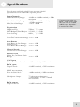
6 Specifications
For the more technical-minded, here are some detailed
specifications for the MultiMix’s operating levels.
Input Channels
Mic In Sensitivity Range:
Mic/Line Gain Range:
-60dBu to –10dBu nominal, +5dBu
maximum
-40dBu to -+10dBu nominal,
+25dBu maximum
+10 to +60dB
Equalization
High-Pass Filter:
High Shelving:
Mid Bandpass/Band Reject:
Low Shelving:
75Hz, 18dB/octave
12kHz, +/- 15dB
2.5 kHz, +/- 15dB
80Hz, +/- 15dB
Line In Sensitivity Range:
All measurements done over
a 22Hz – 22kHz range with a
1kHz sine wave at +18dBu
(-1dBFS) input. Impedances
are measured at 1kHz.
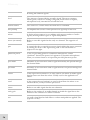
Aux Sends
Aux Send A & B Gain Range: -∞ to +10dB
Aux Returns
Aux Return A Gain Range:
Effects Level/
Aux Return B Gain Range:
-∞ to +15dB
-∞ to +15dB
Channel Levels
Channel Level Gain Range:
-∞ to +10dB
Master Levels
Main Mix, Ctrl Room Gain
Range:
-∞ to +10dB
1/4” Inputs
Stereo Aux Return Level:
+4dBu nominal, +20dBu maximum
RCA Inputs
Tape In Level:
-10dBV nominal, +5dBV maximum
1/4” Outputs
Main Mix, Ctrl Room,
Ext Aux Send Level:
+4dBu nominal, +20dBu maximum
Headphone Output:
RCA Outputs
Tape Out Level:
75 ohm output impedance
>105mW into 75 ohms, >40mW
into 600ohms
-10dBV nominal, +5dBV maximum
31
6
Specifications
This page intentionally left blank
32
7 Block Diagram
33
7
Block Diagram
This page intentionally left blank
34
Glossary
Here are the definitions to some terms you’ll probably encounter
while using your MultiMix-8FX.
Term
Definition
aux (auxiliary)
An additional set of outputs and inputs found on many mixers. These
allow the addition of external effects and other audio sources.
balance
A control that lets you control the position of sound in a stereo signal by
altering the relative levels of the left and right channels.
bus
The electrical component that carries signals from multiple sources to a
single destination such as an amplifier.
channel
A path through which an audio signal flows.
channel strip
A section of a mixer on which reside controls like a fader, EQ and pan
for manipulating the signal of an input channel.
clipping
The cutting of an audio signal caused by a level that is too great for a
mixer circuit to handle.
condenser
microphone
A type of high-quality microphone that produces a weak signal, usually
requiring an external power source like the ones provided by your
MultiMix-8FX’s XLR mic inputs.
dB (decibel)
A common unit of measure for audio.
detent
A point of resistance in the path that a mixer knob or fader travels.
Detents are used to mark important settings. As you turn the knob or
slide the fader, you’ll feel it “click” into the detent.
dry
Term used to describe an audio signal free of effects. The opposite of
“wet.”
dynamic
microphone
A common type of microphone that does not require external power.
Dynamic microphones are generally cheaper than condenser
microphones.
effects processor
A unit whose purpose is to provide effects for audio signals. Some
common effects include reverb, chorus, flange and delay. Effects
processors come in many shapes and sizes, from small pedals up to
rectangular rackmount units.
EQ (equalizer)
The part of your mixer (or other device) that manipulates an audio signal
by lowering the level of some frequencies and increasing the levels of
others. EQ is used to fine-tune a signal’s highs and lows.
gain
The measure of extra amplification applied to an audio signal. Channels
1 – 4 on your MultiMix-8FX have gain controls, which are useful for
35
Glossary
boosting mic and line signals.
36
level
The amount of power driving an audio signal. The most common
names given to levels of varying voltage are, from lowest to highest,
microphone level, instrument level and line level.
master section
The section of a mixer where the main mix is controlled.
mic preamp
An amplifier that boosts a microphone-level signal up to line level.
mixer
A device whose purpose is to combine and output a number of audio
signals, allowing various types of signal manipulation.
mono (monaural)
Refers to an audio signal that has only one channel. The opposite of
stereo.
pan
A control that lets you position a mono signal within the stereo spectrum
by altering the level of the signal being sent to the left channel as
opposed to the right.
phantom power
A way of providing power to condenser microphones. Called
“phantom” because the power isn’t apparent to dynamic microphones
when you connect them to an input that provides phantom power.
post-fader
Describes an aux send that sends a signal that already has passed through
the channel fader.
pre-fader
Describes an aux send that sends a signal that has not passed through the
channel fader.
return
A line input whose function is to carry back to the mixer an audio signal
that has been sent from the mixer. Usually used in the application of
effects.
send
A line output whose function is to send a signal from the mixer to an
external device, usually an effects processor.
stereo
Refers to an audio signal that has two channels.
unity gain
Refers to the setting of an audio channel at which the signal leaves the
channel at the same level at which it entered.
wet
An audio signal that has had effects or other manipulations applied. The
opposite of “dry.”
Warranty / Contact
Alesis Limited Warranty
ALESIS CORPORATION ("ALESIS") warrants this product to be free of defects
in material and workmanship for a period of one (1) year for parts and for a period of
one (1) year for labor from the date of original retail purchase. This warranty is
enforceable only by the original retail purchaser and cannot be transferred or assigned.
For the most effective service, the purchaser should register the purchase on the
ALESIS website at http://www.alesis.com/support/warranty.htm.
During the warranty period ALESIS shall, at its sole and absolute option, either repair
or replace free of charge any product that proves to be defective on inspection by
ALESIS or its authorized service representative. In all cases disputes concerning this
warranty shall be resolved as prescribed by law.
To obtain warranty service, the purchaser must first call or write ALESIS at the
address and telephone number available on the Alesis Website to obtain a Return
Authorization Number and instructions concerning where to return the unit for
service. All inquiries must be accompanied by a description of the problem. All
authorized returns must be sent to ALESIS or an authorized ALESIS repair facility
postage prepaid, insured and properly packaged. Proof of purchase must be
presented in the form of a bill of sale, canceled check or some other positive proof
that the product is within the warranty period. ALESIS reserves the right to update
any unit returned for repair. ALESIS reserves the right to change or improve design
of the product at any time without prior notice.
This warranty does not cover claims for damage due to abuse, neglect, alteration or
attempted repair by unauthorized personnel, and is limited to failures arising during
normal use that are due to defects in material or workmanship in the product.
THE ABOVE WARRANTIES ARE IN LIEU OF ANY OTHER
WARRANTIES OR REPRESENTATIONS WHETHER EXPRESS OR
IMPLIED OR OTHERWISE, WITH RESPECT TO THE PRODUCT, AND
SPECIFICALLY EXCLUDE ANY IMPLIED WARRANTIES OF FITNESS
FOR A PARTICULAR PURPOSE OR MERCHANTABILITY OR OTHER
IMPLIED WARRANTIES. Some states do not allow limitations on how long an
implied warranty lasts, so the above limitation may not apply to you.
IN NO EVENT WILL ALESIS BE LIABLE FOR INCIDENTAL,
CONSEQUENTIAL, INDIRECT OR OTHER DAMAGES RESULTING
FROM THE BREACH OF ANY EXPRESS OR IMPLIED WARRANTY,
INCLUDING, AMONG OTHER THINGS, DAMAGE TO PROPERTY,
DAMAGE BASED ON INCONVENIENCE OR ON LOSS OF USE OF THE
PRODUCT, AND, TO THE EXTENT PERMITTED BY LAW, DAMAGES
FOR PERSONAL INJURY. Some states do not allow the exclusion or limitation of
incidental or consequential damages, so the above limitation or exclusion may not
apply to you.
THIS CONTRACT SHALL BE GOVERNED BY THE INTERNAL LAWS OF
THE STATE OF CALIFORNIA WITHOUT REFERENCE TO CONFLICTS
OF LAWS. This warranty gives you specific legal rights, and you may also have other
rights required by law which vary from state to state.
This warranty only applies to products sold to purchasers in the United States of
America or Canada. The terms of this warranty and any obligations of Alesis under
this warranty shall apply only within the country of sale. Without limiting the
foregoing, repairs under this warranty shall be made only by a duly authorized Alesis
service representative in the country of sale. For warranty information in all other
countries please refer to your local distributor.
For more effective
service and product
update notices, please
register your
MultiMix-8FX online
at:
http://www.alesis.com/
support/warranty.htm
37
Warranty/Contact
Alesis Contact Information
Alesis Distribution, LLC
Los Angeles, CA USA
E-mail:
Web site:
[email protected]
http://www.alesis.com
MultiMix-8FX Reference Manual
Revision 1.0 by Edwin Erdmann
Copyright 2002, Alesis Distribution, LLC. All rights reserved
Reproduction in whole or in part is prohibited. “MultiMix-8FX” is
a trademark of Alesis Distribution, LLC. Specifications subject to
change without notice.
7-51-0130-A
1/07/2003
38