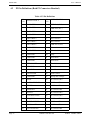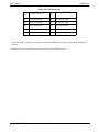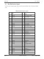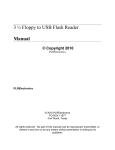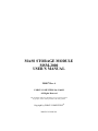
1
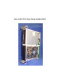
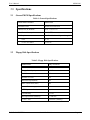
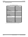
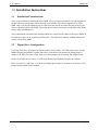
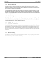
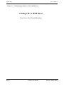
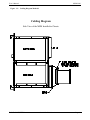
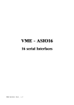
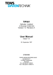
MASS STORAGE MODULE MSM-2000 USER’S MANUAL 208817 Rev A FORCE COMPUTERS Inc./GmbH All Rights Reserved This document shall not be duplicated, nor its contents used for any purpose, unless written permission has been granted. Copyright by FORCE COMPUTERS 20000213 420 000 AA MAIN OFFICES Headquarters Branch Offices Corporate Headquarters FORCE COMPUTERS Inc. 2001 Logic Drive San Jose, CA 95124-3468 U.S.A. Phone : (408) 369-6000 FAX : (408) 371-3382 FORCE COMPUTERS S.A.R.L Le Volta 17-19 Rue. Jeanne Braconnier F-92366 Meudon-La-Foret/ Cedex France Phone : (33) 1 41 07 95 15 FAX : (33) 1 45 37 06 19 European Headquarters FORCE COMPUTERS GmbH Prof.-Messerschmitt-Str. 1 D-85579 Neubiberg/Munchen Germany Phone : (49) 89 608-14-0 FAX : (49) 89 609 77 93 FORCE COMPUTERS UK Ltd. Alton House Office Park Gateway House Aulesbury, Bucks. HP19 3XU England Phone : (44) 12 96 31 0400 FAX : (44) 12 96 31 0420 Japanese Headquarters FORCE COMPUTERS Japan KK Miyakeya Building 4F 1-9-12 Hamamatsu-cho Minato-ku Tokyo 105 Japan Japan Phone : (81) 3 3437 3948 FAX : (81) 3 3437 3968 FORCE COMPUTERS UK Ltd. (Sweeden) Riksapplet, Marinens vag 30 S-13640 Haninge Sweeden Phone : (08) 707 30 50 FAX : (08) 707 30 51 FORCE COMPUTERS Inc. (Latin America) 3939 Beltline Road, Suite 570 Dallas, TX 75244-2217 Phone : (214) 243-1888 FAX : (214) 243-6971 N O T E: The information in this document has been carefully checked and is believed to be entirely reliable. FORCE COMPUTERS makes no warranty of any kind with regard to the material in this document, and assumes no responsibility for any errors which may appear in this document. FORCE COMPUTERS reserves the right to make changes without notice to this, or any of its products, to improve reliability, performance, or design. FORCE COMPUTERS assumes no responsibility for the use of any circuitry other than circuitry which is part of a product of FORCE COMPUTERS Inc./GmbH. FORCE COMPUTERS does not convey to the purchaser of the product described herein any license under the patent rights of FORCE COMPUTERS Inc./GmbH nor the rights of others. TABLE OF CONTENTS General Information 10 Specifications 12 General MSM Specifications 12 Floppy Disk Specifications 12 Hard Disk Specifications 13 Installation Instructions 14 Installation Considerations 14 Floppy Drive Configuration 14 MTR_ON Jumper field 15 Hard Disk Configuration 15 SCSI Bus Termination 15 Disk Formatting 15 Cabling Diagrams 16 Hardware User’s Manual 20 P1 Pin Definitions (Both P1 Connectors Identical) 22 P2 Pin Definitions (Both P2 Connectors Identical) 23 Floppy Disk Interface Signals 25 Hard Disk Interface Signals 27 SCSI Bus Termination 28 Schematics 28 Copies of Device Data Sheets 30 Customer Product Error Report 32 iv TABLE OF CONTENTS v LIST OF TABLES Table 1: Table 2: Table 3: Table 4: Table 5: Table 6: General Specifications . . . . . . . . . . . . . . . . . . . . . . . . . . . . . . . . . . . . . . . . . . . . Floppy Disk Specifications. . . . . . . . . . . . . . . . . . . . . . . . . . . . . . . . . . . . . . . . . Hard Disk Specifications . . . . . . . . . . . . . . . . . . . . . . . . . . . . . . . . . . . . . . . . . . P2 Pin Definitions. . . . . . . . . . . . . . . . . . . . . . . . . . . . . . . . . . . . . . . . . . . . . . . . Floppy Disk Interface Signals . . . . . . . . . . . . . . . . . . . . . . . . . . . . . . . . . . . . . . Hard Disk Interface Signals . . . . . . . . . . . . . . . . . . . . . . . . . . . . . . . . . . . . . . . . 12 12 13 23 25 27 User’s Manual MSM-2000 1.0 General Information The Force Mass Storage Module (MSM) is a high quality, highly reliable, VMEbus form factor module that provides up to 2 Gigabytes of 3.5" SCSI Hard Disk drive and a 2 MB (unformatted) Slim line 3.5" Floppy Drive in a two slot package. The MSM is cable compatible with Force SPARC Single Board Computers. The MSM combines popular 3.5" products into a package that can be put into a VMEbus backplane and be connected to various Force single board computers with a single 64 pin flat cable. Other SCSI and SA460 disk controllers can be used by using the IOPI backpanel and cabling. All P2 connections are passed through the MSM to allow multiple MSMs to be cascaded for additional capacity and flexibility. In addition, both P1 connectors pass the four Bus Grant signals and the daisy chain IACK signal. In case one needs to use the serial or parallel signals, or to interface to another floppy or SCSI interface device an IOPI can be inserted into the second P2 and then a standard SCSI and floppy interface cables can be used. The mechanical assembly is adjustable to insure proper spacing and compliance to the VMEbus form factor. Power is drawn from the +5V and +12V pins on the VME P1 connectors. CAUTION: Please allow 25 Seconds MINIMUM spin down before removal. FORCE COMPUTERS 20000213 420 000 AA Page 10 MSM-2000 User’s Manual This page was intentionally left blank Page 11 20000213 420 000 AA FORCE COMPUTERS User’s Manual MSM-2000 2.0 Specifications 2.1 General MSM Specifications Table 1: General Specifications 2.2 MSM Model Number MSM 2000 Mechanical Info Double Eurocard 2 Slot Dimensions (in) HxDxW 10.31 x 7.43 x 1.59 Total Power Consumption <30 WATTS DC Requirements Both P1s Must have all grounds supplied. +5.0V <1.44 +12.0V TYP/MAX .57A/1.9A Floppy Disk Specifications Table 2: Floppy Disk Specifications Manufacture Sony or Similar Series Number MPF920-1 Floppy Disk Capacity 2.0 MB Disk Size 3.5" Number of Tracks 160 Rotational Speed(RPM) 300 Data Transfer Rate (Kb/s) 500 Access Time Average (ms) 94 MTBF (power on hour) 30,000 Track Density 135 TPI DC Requirements (stand-by) 17 mW max. +5.0V ± 10% 3 mA max. (stand by) FORCE COMPUTERS 20000213 420 000 AA Page 12 MSM-2000 2.3 User’s Manual Hard Disk Specifications Table 3: Hard Disk Specifications Manufacture Seagate or Similar Series/Model Number ST32272N Hard Disk Capacity 2 GB Disk Size 3.5" Sector Size (Bytes) 512/(factory) MTBF (power on hours) 1,000,000 Cache Size (Bytes) 512K Number of Cylinders 26,311 Number of Disk 2 Number of Heads 4 Number of Bytes/Track 124,000 (Average, unformatted) Number of Blocks/Track (512K) varies Average Seek Time (ms) 9.4 (Read), 10.4 (Write) Track Density (TPI) 6,800 +5.0V ± 5% .81A +12.0V Typ/Max ± 10% .85A See the hard disk manual within this document for more information. Page 13 20000213 420 000 AA FORCE COMPUTERS User’s Manual MSM-2000 3.0 Installation Instructions 3.1 Installation Considerations There are two methods of installing the Force MSM. The most common method is to use the supplied 64 Pin flat cable that is designed to connect P2 of the Force SPARC single board computers to P2 of the MSM- 1000. Just plug the MSM into two P1 VME slots and connect the 64 Pin flat cable to the P2 connector of the leftmost P2 on the MSM. Insure that there is sufficient clearance on both sides of the MSM and any other installed devices. The second method of installing and cabling the MSM is to install an IOPI adapter in the lowest numbered P2 connector in place of the supplied 64 pin flat cable. This IOPI allows industry standard cabling to be used to connect to the MSM. 3.2 Floppy Drive Configuration The Floppy Disk Drive is jumpered to respond to drive select 0 (DS0*). The DS0* input comes from the MSM backpanel jumperfield J5 and the actual drive select number is determined by which jumper is inserted in J5; DS3, DS2, DS1 or DS0. Only one of these jumpers can be inserted. The default is DS0. See the device data sheet in section 3.3 of the Sony Product Specification included in this manual. Refer to section 3.5.2 and figure 3.3 of the Sony Product Specification for information on the drive select jumper location and the factory defaults. FORCE COMPUTERS 20000213 420 000 AA Page 14 MSM-2000 3.2.1 User’s Manual MTR_ON Jumper field Normally the FDD is configured to start the motor when the MTR_ON signal is asserted. For those boards/drivers that do not drive the MTR_ON signal, the MSM can be jumpered to start the motor on the Drive Select that is configured on jumperfield J5. To start the FDD motor with the Drive Select signal, insert a jumper into J6 in the DS position. To select the FDD motor on the Motor-on signal, insert a jumper into J6 in the MTR position. (This is the default position). It is recommended that only one jumper be left in J6 because back circuits can be created which could cause multiple selects. 3.2.2 Hard Disk Configuration The SCSI Hard Disk Drive can be jumpered for different unit addresses according to the SCSI Target ID's. See Hard Disk Drive manual for jumper information. The SCSI bus Hard Disk drive can be configured to respond to unit addresses 0-7. Factory default for Solaris is 3. 3.3 SCSI Bus Termination Each SCSI BUS signal is terminated at the physical start and the physical end of the SCSI bus. Therefore, the terminators are removed from the SCSI device to insure that there are no terminators except at each physical extreme of the bus. A 50 pin terminator is supplied in a bag to terminated the end of the SCSI bus. Power for the SCSI bus terminators is expected on pin 26 of the SCSI cable and is jumper selectable on the drive. 3.4 Disk Formatting The MSM comes standard with a preformatted hard disk for Solaris. See your operating system manuals for instructions if your drive ever needs reformatting. Page 15 20000213 420 000 AA FORCE COMPUTERS User’s Manual 3.5 MSM-2000 Cabling Diagrams FORCE COMPUTERS 20000213 420 000 AA Page 16 MSM-2000 User’s Manual Figure 3-1: Cabling Diagram Method 1 (CPU to MSM direct) Cabling CPU to MSM Direct Rear View of the Chassis/Backplane Page 17 20000213 420 000 AA FORCE COMPUTERS User’s Manual Figure 3-2: MSM-2000 Cabling Diagram Method 2 Cabling Diagram Side View of the MSM Installed in Chassis FORCE COMPUTERS 20000213 420 000 AA Page 18 MSM-2000 Page 19 User’s Manual 20000213 420 000 AA FORCE COMPUTERS User’s Manual MSM-2000 4.0 Hardware User’s Manual FORCE COMPUTERS 20000213 420 000 AA Page 20 MSM-2000 User’s Manual This page was intentionally left blank Page 21 20000213 420 000 AA FORCE COMPUTERS User’s Manual 4.1 MSM-2000 P1 Pin Definitions (Both P1 Connectors Identical) The following pins are installed and connected on each P1 connector on the MSM: Ground - A09,A11,A15,A17,A19,B20,B23,C09 (Connected to GND Plane) +5V - A32, B32, C32 (Connected to +5V Plane) +12V - C31 (Connected to +12V Plane) IACKIN* to IACKOUT* - A21 to A22 BG0IN* to BG0OUT* - B04 to B05 BG1IN* to BG1OUT* - B06 to B07 BG2IN* to BG2OUT* - B08 to B09 BG3IN* to BG3OUT* - B10 to B11 See schematics for further information. FORCE COMPUTERS 20000213 420 000 AA Page 22 MSM-2000 4.2 User’s Manual P2 Pin Definitions (Both P2 Connectors Identical) Table 4: P2 Pin Definitions Pin No. Page 23 Pin No. SIGNAL ROW A SIGNAL ROW C 1 DATA BUS 0 1 FDD Pin 2 (N/C) 2 DATA BUS 1 2 FDD Pin 4 (N/C) 3 DATA BUS 2 3 FDD Pin 6 (N/C) 4 DATA BUS 3 4 Index- 5 DATA BUS 4 5 Drive Select 0 6 DATA BUS 5 6 Drive Select 1 7 DATA BUS 6 7 FDD Pin 14 (N/C) 8 DATA BUS 7 8 Motor On- 9 DATA BUS P 9 Direction Select- 10 GROUND* 10 Step- 11 GROUND* 11 Write Data- 12 GROUND* 12 Write Gate- 13 TERMPOWER 13 Track 00- 14 GROUND* 14 Write Protected- 15 GROUND* 15 Read Data- 16 ATTENTION 16 Side 1 Select- 17 GROUND* 17 Ready/Disk Change- 18 BUSY 18 N/U Passed Thru 19 ACKNOWLEDGE 19 N/U Passed Thru 20 RESET 20 N/U Passed Thru 21 MESSAGE 21 N/U Passed Thru 22 SELECT 22 N/U Passed Thru 23 CONTROL/DATA 23 N/U Passed Thru 24 REQUEST 24 N/U Passed Thru 25 INPUT/OUTPUT 25 N/U Passed Thru 26 N/U Passed Thru 26 N/U Passed Thru 27 N/U Passed Thru 27 N/U Passed Thru 20000213 420 000 AA FORCE COMPUTERS User’s Manual MSM-2000 Table 4: P2 Pin Definitions Pin No. SIGNAL ROW A Pin No. SIGNAL ROW C 28 N/U Passed Thru 28 N/U Passed Thru 29 N/U Passed Thru 29 N/U Passed Thru 30 N/U Passed Thru 30 N/U Passed Thru 31 N/U Passed Thru 31 N/U Passed Thru 32 N/U Passed Thru 32 N/U Passed Thru "N/U Passed Thru" indicates the signal is not used on the MSM but is just passed from one P2 connector to the other. GROUND* These Signals are defined as Ground by the SCSI Specification. FORCE COMPUTERS 20000213 420 000 AA Page 24 MSM-2000 4.3 User’s Manual Floppy Disk Interface Signals The Floppy Disk Interface is a standard SA 460 interface to accommodate industry standard 3.5" slim line disk drives. The signals are defined as follows: Table 5: Floppy Disk Interface Signals Pin No. Signal Name Pin No. Signal Name 1 NC 2 Not Connected 3 NC 4 Not Connected 5 NC 6 Not Connected 7 Ground 8 Index- 9 Ground 10 Drive Select 0- 11 Ground 12 Drive Select 1 13 Ground 14 Not Connected 15 Ground 16 Motor On- 17 Ground 18 Direction Select- 19 Ground 20 Step- 21 Ground 22 Write Data- 23 Ground 24 Write Gate- 25 Ground 26 Track 00- 27 Ground 28 Write Protected- 29 Ground 30 Read Data- 31 Ground 32 Side 1 Select- 33 Ground 34 *Ready/Disk Change *Pin 34 can be configured on the drive. See drive Data Sheet for information. Page 25 20000213 420 000 AA FORCE COMPUTERS User’s Manual MSM-2000 SIGNAL DEFINITIONS: RESERVED - For future expansion. INDEX -There is a pulse on this signal to indicate that a hole has been detected in the media. There is one hole that is used to signal the beginning of a track. DRIVE SELECT 0-1 There are two drive select signals to select the drive. The MSM jumper (J5) allows the FDD to respond to one of these drive selects. MOTOR ON -The spindle motor runs when this signal is active. Some drives may require a delay after motor on before reads or writes may be attempted. DIRECTION SELECT- This signal is used to indicate which direction to move the floppy drive heads when the step signal is issued. When active (-), the heads are moved toward the higher numbered tracks. STEP - A one microsecond pulse to the floppy drive causes the read/write heads to move one track. The direction depends upon the direction select signal above. WRITE DATA -A pulse on this signal causes the floppy disk drive to write a data bit on the media if the write gate is active. WRITE GATE -An active level on this pin signals the floppy disk drive to allow writing on the media if the write data signal is pulsed. Insure that all start-up, head settle times and head load times have been complied with before issuing this signal. TRACK 00 -This signal from the floppy disk drive indicates that the heads are positioned at track 00. WRITE PROTECTED-This signal when low or negative indicates that the media in the drive presently has the write enable/disable slide in the disable position. READ DATA -The floppy disk drive will send a pulse on this line when a bit is detected on the media. SIDE 1 SELECT -This is a signal to the floppy disk drive to select the upper head/head one. READY/DISK CHANGE- This signal is configurable on the floppy disk drive. When configured for READY, it indicates that the drive contains the proper media. When configured for DC, it indicates if the media has been changed since the last time a step pulse has been issued. DISK CHANGE -This signal comes from the floppy to the controller to indicate whether or not a diskette has been changed since the last step pulse issued. FORCE COMPUTERS 20000213 420 000 AA Page 26 MSM-2000 4.4 User’s Manual Hard Disk Interface Signals There are a total of eighteen signals. Nine are used for control, and nine for data. The data bus includes parity. Table 6: Hard Disk Interface Signals Pin No. Page 27 Signal Name Pin No. Signal Name 1 Ground 2 DATA BUS 0 (DB0) 3 Ground 4 DATA BUS 1 5 Ground 6 DATA BUS 2 7 Ground 8 DATA BUS 3 9 Ground 10 DATA BUS 4 11 Ground 12 DATA BUS 5 13 Ground 14 DATA BUS 6 15 Ground 16 DATA BUS 7 (DB7) 17 Ground 18 DATA BUS P (DBP) 19 Ground 20 GROUND 21 Ground 22 GROUND 23 Ground 24 GROUND 25 Ground 26 TERMPOWER 27 Ground 28 GROUND 29 Ground 30 GROUND 31 Ground 32 ATTENTION 33 Ground 34 GROUND 35 Ground 36 BUSY 37 Ground 38 ACKNOWLEDGE 39 Ground 40 RESET 41 Ground 42 MESSAGE 43 Ground 44 SELECT 45 Ground 46 CONTROL/DATA 47 Ground 48 REQUEST 49 Ground 50 INPUT/OUTPUT 20000213 420 000 AA FORCE COMPUTERS User’s Manual MSM-2000 SIGNAL DEFINITIONS BUSY -An "OR-tied" signal that indicates the bus is being used. SELECT -A signal used by an initiator to select a target or by a target to reselect an initiator. CONTROL/DATA A signal driven by a target that indicates whether CONTROL or DATA information is on the data bus. True indicates CONTROL. INPUT/OUTPUT A signal driven by a target that controls the direction of data movement on the data bus with respect to the initiator. True indicates input to the initiator. This signal is also used to distinguish between SELECTION and RESELECTION process. MESSAGE - A signal driven by a target during the MSG phase. REQUEST -A signal driven by a target to indicate a request for a REQ/ACK data transfer handshake. ACKNOWLEDGE -A signal driven by an initiator to indicate an acknowledgment for REQ/ACK data transfer handshake. ATTENTION -A signal driven by an initiator to indicate an ATTENTION condition. RESET - An "OR-tied" signal that indicates the RESET condition. DATA BUS 0-7,P Eight Data bits and a Parity bit which together form a data bus. DB7 is the most significant bit, and has the highest priority during the ARBITRATION phase. Bit number, significance, and priority decrease as the bit number decreases. A data bit is defined as one when the signal value is true and a zero when the signal is false. Data parity DB(P) is odd. The use of parity is a system option (i.e., a system configured so that all SCSI devices on a bus generate parity and have parity detection enabled, or all SCSI devices have parity detection disabled or not implemented.) Parity is not valid during the ARBITRATION phase. 4.5 SCSI Bus Termination Each SCSI BUS signal is terminated at the physical start and the physical end of the SCSI bus. Therefore, the terminators must be removable from any SCSI devices to insure that there are no terminators except at each physical extreme of the bus. See section 3.3 4.6 Schematics FORCE COMPUTERS 20000213 420 000 AA Page 28 MSM-2000 User’s Manual This page was intentionally left blank Page 29 20000213 420 000 AA FORCE COMPUTERS User’s Manual MSM-2000 5.0 Copies of Device Data Sheets Abbreviated SONY MPF920-1 (or similar) Abbreviated SEAGATE ST32272N Hard Disk Drives Product Manual (or similar) FORCE COMPUTERS 20000213 420 000 AA Page 30 MSM-2000 User’s Manual This page was intentionally left blank Page 31 20000213 420 000 AA FORCE COMPUTERS User’s Manual MSM-2000 6.0 Customer Product Error Report FORCE COMPUTERS 20000213 420 000 AA Page 32 MSM-2000 User’s Manual This page was intentionally left blank Page 33 20000213 420 000 AA FORCE COMPUTERS