1
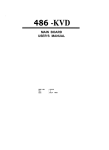
!!
.
i
J
b
I
;
,I
:
- BSeagate
_. .
.
l
.
.
.
.
.
.
.
.
.
.
.
.
.
.
.
.
.
.
.
.
.
.
.
.
.
ST3144 Family:
.
.
.
.
.
.
.
.
.
.
.
.
.
.
.
.
.
.
.
.
.
.
.
.
.
.
.
.
.
.
.
.
.
.
.
.
.
.
.
.
.
.
.
.
.
.
.
.
.
.
.
.
.
.
.
.
.
.
.
.
.
.
.
.
.
.
.
.
.
.
.
.
.
.
.
.
.
.
.
.
.
.
.
.
ST3096A,
.
.
.
.
.
.
.
.
.
ST312OA,
.
.
.
.
.
.
.
.
.
.
ST3144A
.
.
.
.
.
.
.
.
.
lnstalla tion Guide
.
.
.
.
.
.
.
.
.
.
.
.
.
.
.
.
.
_. . _
Contents
.
...
.
.
.
.
.
.
.
.
.
.
.
3
. . . . . . . . . . .
.
.
.
.
.
.
.
.
.
.
.
4
.
.
.
.
.
.
.
.
.
.
.
.
.
.
.
.
.
.
.
.
.
.
.
.
.
.
.
.
.
.
.
.
.
.
.
.
.
.
.
.
.
.
.
.
.
.
.
.
.
.
.
.
.
.
.
.
.
.
.
.
.
.
.
.
.
.
.
.
.
.
.
.
.
.
.
.
.
5
5
6
6
7
7
IO
.
.
.
.
.
.
.
.
.
.
.
IO
.....
.
.
.
.
.
.
.
.
.
.
.
11
....
.
.
.
.
.
.
.
.
.
.
.
11
Read before you begin
Overview
ST3144 family drives
....
Power management option
AT
interface
setup
......
AT drive geometries . . . ,
Compatible BIOS revisions
Configuring and installing the drive
Drive
formatting
. . . . . . s . . . .
Mounting specifications
.......
Frame kit and remote LED
Installation trouble-shooting
0 1992 Seagate Technology, Inc. All rights reserved
Publication Number: 36169-002, Rev. D
Seagate@, Seagate Technology@, and the Seagate logo are
registered trademarks of Seagate Technology, Inc. SeaFAXTM,
SeaFONETM, and SeaBoard TM, and SeaCacheTM are trademarks of
Seagate Technology, Inc. Other product names are registered
trademarks or trademarks of their owners.
Seagate reserves the right to change,’ without notice, product”
offerings or specifications. No part of this publication may be .
reproduced in any form without w ritten permission of Seagate
Technology, Inc.
ST3144 Family installation Guide, Rev. D
4
Overview
Installation of the drive can be divided into distinct steps as
outlined below. Some of these may not be applicable to your
particular installation requirements. Refer to the drive installation
section for specific information on your drive model.
Drive jumper settings. Select the appropriate drive features
by installing or removing jumpers on the jumper blocks on the
drive circuit board.
CMOS configuration. Basic information about the drive must
be entered into the host system CMOS so that it may properly
access the drive for reading and writing data. The number of
heads, cylinders, and sectors per track are specific to each
drive and collectively define the drive’s geometry.
Low-level formatting. Seagate AT interface drives are lowlevel formatted at the factory and do not need low-level formatting.
Partitioning. A drive can be divided into partitions that behave
as individual drives within the system. Versions of DOS earlier
than 4.0 limit the maximum drive capacity and consequently
require higher capacity drives to be divided into smaller partitions. For DOS users, each partition is assigned a different
letter, for example, C: and D: for a drive with two partitions.
Use the DOS FDISK utility to partition the drive. After the drive
has been defined in CMOS, you must boot the system to the
floppy drive with a bootable DOS diskette. Then run the FDISK
utility to partition the drive. Refer to your DOS manual for using
FDISK. Use DOS 3.3 or higher.
Caution. If you partition or format a drive at any level, you
erase all your data. Backup the drive first. Seagate assumes
no liability for lost user data.
5
ST3144 Family Installation Guide, Rev. D
l
High-level formatting, This procedure verifies the information written by the low-level format and establishes drive
access information used by the system. High-level formatting
also creates the File Allocation Table (FAT) used by DOS for
drive access. The high-level format is initiated by the FORMAT
command. Refer to your DOS manual for instructions on using
the FORMAT command.
ST31 44 family drives
This guide provides installation information for the ST3096A,
ST31 20A, and ST31 44A drives. All drives in this family automatically park their heads at power-down.
Power management option
ST31 44 family drives are available with power management. The
identifying nine-digit number is found on the drive. Use of this
feature is system-dependent.
Drive Model
ST31 20A
ST31 44A
Supports Power
Management
Without Power
Management
911008-0XX,
911008-I XX,
911008-4XX,
911008-6XX
911008-3XX
911008-5XX
911003-0XX,
911003-1 xx,
911003-4XX,
911003-6XX
911003-3XX,
911003-5xx
911006-0XX,
911006-4Xx,
911006-6XX
,
911006-3Xx,
911006-5XX
1
ST3144 Family Installation Guide, Rev. D
6
AT interface setup
This section describes drive geometries, compatible BIOS revisions, jumper settings, and’ installation procedures for ST3144
family drives.
AT drive geometries
The following table shows the recommended drive geometries
for ST31 44 family drives.
Formatted
CMOS
MBytes !
Sectors/
Heads T r a c k
Model
Formatted
MBytes
Cyl.
’ ST3096A ’
89.1
1,024
10
17
85.0
ST31 20A
106.9
1,024
12
17
102.0
/ ST3144A
130.7
1,001
15
17
/
!
/
I
124.6
Use a system utility, usually called SETUP, to enter the drive
geometry into the system CMOS. If the drive types offered by the
CMOS do not support the number of heads, cylinders, and
sectors/track shown by the table, and your system does not
support a “user-defined” drive type, select a drive type in your
system CMOS with a capacity less than or equal to the capacity
given in the “Formatted CMOS Megabytes” column of the table
above.
Note. The number of Heads times the number of Sectors cannot
exceed 255, as given by the following equation:
(Heads) x (Sectors) L 255
When you enter the drive geometry using the “user-defined” or
“custom” drive type, the CMOS calculates the drive capacity. T h i s
capacity is listed in the “Formatted CMOS Megabytes” column of
the table. It is the same effective capacity as the capacity shown _
in the “Formatted Megabytes” column, even though the CMOS
value is lower. After high-level formatting, you can check the drive
ST3144 Family Installation Guide, Rev. D
7
capacity using the DOS CHKDSK utility. If you do not know what
drive types your CMOS supports, use the FINDTYPE utility from
the Seagate Technical Support BBS to assist you in choosing an
appropriate drive type. See Page 2.
_
Compatible BIOS revisions
ST3144 family drives are compatible with the BIOS revisions
listed in the table below. To find out which BIOS your system
uses, reboot the system. The BIOS manufacturer, version, and
date are displayed on the monitor.
Typically, BIOS compatibility problems include intermittent drive
access errors or system time-out errors. If you have compatibility
problems, call your system dealer or manufacturer.
I
1 BIOS Manufacturer
I American Megatrends
1
/
f
I
Version
Dated 4/9/90 or later
Award
Version 3.04 or higher
Quadtel
Single Drive System: Any Version
Dual Drive System: 3.04 or higher
Phoenix
BIOS Plus 286: 3.10 or higher
BIOS Plus 386: 1 .1 0 or higher
PhoenixBlOS
Version 1 .OO or higher
Configuring and installing the drive
1. Turn off the system power.
2. Wear a grounded wrist strap. If you are grounding yourself
to the chassis of the host computer, the power cord must be
plugged into an electrical outlet that has an earth ground.
I
ST3144 Family Installation Guide, Rev. D
8
3. Master/Slave configuration. The table below defines jumper
settings for configuring up to two drives on a single AT bus,
Refer to Figure 1 for jumper locations.
I
System Configuration
Jumper
Master
Slave Present
Only drive in system
Installed
Removed
Drive l in a two-drive system
Installed
Installed
Drive 2 in a two-drive system
Removed
Removed
i
4. Drive Activity LED jumper. If you install a jumper on pins 9
and 10 of the User Configuration jumper block, the drive
indicates activity to the system through a connector on the host
adapter or motherboard.
5. Attach the 40-pin AT interface cable. A dual-drive system
requires a 40-pin AT interface daisy-chain cable. Pin 20 has
been removed on the connector for keying purposes.
Most interface cables have a stripe on one side to designate
Pin I. Make sure Pin 1 on the cable connector is aligned to Pin
1 on the drive connector and Pin I on the host connector. The
maximum cable length is 18 inches (457 mm).
For systems without an embedded AT interface connector on
the motherboard, Seagate offers the ST07A/ST08A AT interface host adapters.
Note. To prevent improper pin alignment during installation, it
is recommended that the mating cable connector be keyed, by
inserting a plug into the Pin-20 location of the cable connector.
6. Attach a system power cable to the drive power connector. The ST31 44 family drives have both 3-pin and 4-pin power
connectors.
7. Mount the drive in the host system chassis.
ST3144 Family Installation Guide, Rev. D
9
_ms PCB
+5 VDC
+5 Volts Return
+12
+12
4-Pin DC Power
‘Ground
1 O-Pin
User Configuration Block
3-Pin DC Power
I IJ
l
-+12 VDC
j+ 5VDC
,Key
-
Pin 20 removed
L
Figure 1: AT jumpers and connectors
l
l
l
l
1 Master
,
10
ST3144 Family installation Guide, Rev. D
Mounting the drive
You can mount the drive in any orientation, provided you do not
mount it more than 5° from a vertical or horizontal axis. For best
results, format the drive in its final mounting orientation.
Bottom mounting. Insert four mounting screws not more than
0.20 inches (6 full turns) into the drive frame. If you use a screw
that is too long, you could damage the drive.
Side mounting. Insert four mounting screws not more than
0.13 inches (4 full turns) into the drive frame. If you use a screw
that is too long, you could damage the drive.
Screw sizes: Use 6-32 UNC screws on drives with standard-size
mounting holes. These drives have an “S” stamped on the frame
runner. Use M4 screws on drives with metric mounting holes.
These drives have an “M” stamped on the frame runner.
Caution. Be careful not to over-tighten screws. You could damage the drive. (Max torque: 6 inch-lbs)
Formatting the drive
Seagate AT Interface drives are low-level formatted at the factory
and do not need low-level formatting. Partition the drive using the
DOS FDISK utility. Then, high-level format the drive using the
DOS FORMAT utility. Use DOS 3.3 or higher. Consult your DOS
manual for FORMAT and FDISK command syntax. If the drive is
to be made bootable, copy the system files onto it and mark the
primary DOS partition active.
Caution. If you partition or format a drive at any level, you erase
all your data. Backup the drive first. Seagate assumes no liability
for lost user data.
ST3144 Family Installation Guide, Rev. D
11
Frame kit and remote LED
To install this 3.5inch drive in a 5.25inch frame, use a Seagate
frame kit, part number 54459-016. This frame kit can only be used
with drives that have standard-size mounting holes. These drives
have an “S” stamped on each frame runner. If your drive has an
“M” (for metric) stamped on each frame runner, do not attempt
to mount it in this frame kit.) The frame kit contains a remote LED.
Installation trouble-shooting
Before you begin trouble-shooting, read and be aware of all the
considerations discussed in this section. The suggestions presented here resolve the vast majority of installation problems.
Warning. Always power down the system before changing
jumper settings or unplugging cables and cards.
Verify compatibility. Check the documentation for the host
adapter and the drive to confirm that these components are
appropriately matched for each other and to your system.
Verify your configuration. Refer to the drive and controller
installation guides to make sure all jumper settings suit your
configuration requirements.
Check all cables. Make sure all cables are securely connected. Ribbon cables are especially fragile. Make sure they
are not crimped or damaged in any way. Having extra cables
on hand for trouble-shooting saves time and frustration.
Note. Most cables have a stripe on one side to designate the
Pin 1 location. Make sure Pin 1 on the interface cable connector is connected to Pin 1 on the drive interface connector and
Pin 1 on the host connector. Refer to Figure 1 for the location
of Pin 1 on the drive interface connector.
12
ST3144 Familv Installation Guide. Rev. D
Check all cards. Make sure all cards are securely seated in
the expansion slots on the motherboard. Full size (16-bit)
cards cannot be plugged into half-size (8-bit) slots. Make sure
all cards are plugged into appropriately sized expansion slots.
Once the cards are permanently installed, and the system is
running properly, use mounting screws to secure them in
place.
Check the power supply specifications. The output of your
power supply may not meet the power requirements of the new
devices you are installing. If you are not sure whether the
power supply meets the system requirements, consult your
system dealer or distributor.
Use the same version of DOS throughout your system.
The same version of DOS must be used throughout all phases
of building and configuring your system.
Verify the CMOS drive type. The CMOS drive type must
approximate, but not exceed, the physical specifications and
maximum drive capacity of the disc drive. Refer to the Default
Drive Geometry section of this installation guide for drive
specifications and CMOS configuration information.
Check for viruses. Before installing any new software, scan
the installation diskettes for viruses. After the software has
been installed on the hard disc, scan that drive for viruses.
Symptoms of viruses can include intermittent system lock-ups,
re-boots, drive errors, etc.