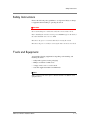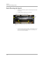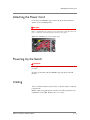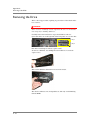
1
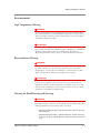
ARX-1000 Hardware Installation Guide
810-0006-00
Publication Date
This manual was published on August 17, 2011.
Legal Notices
Copyright
Copyright 2004-8/17/11, F5 Networks, Inc. All rights reserved.
F5 Networks, Inc. (F5) believes the information it furnishes to be accurate and reliable. However, F5
assumes no responsibility for the use of this information, nor any infringement of patents or other rights of
third parties which may result from its use. No license is granted by implication or otherwise under any
patent, copyright, or other intellectual property right of F5 except as specifically described by applicable
user licenses. F5 reserves the right to change specifications at any time without notice.
Trademarks
3DNS, Access Policy Manager, Acopia, Acopia Networks, Advanced Client Authentication, Advanced
Routing, APM, Application Security Manager, ARX, AskF5, ASM, BIG-IP, Cloud Extender,
CloudFucious, CMP, Data Manager, DevCentral, DevCentral [DESIGN], DNS Express, DSC, DSI, Edge
Client, Edge Gateway, Edge Portal, EM, Enterprise Manager, F5, F5 [DESIGN], F5 Management Pack, F5
Networks, F5 World, Fast Application Proxy, Fast Cache, FirePass, Global Traffic Manager, GTM, IBR,
Intelligent Browser Referencing, Intelligent Compression, IPv6 Gateway, iApps, iControl, iHealth,
iQuery, iRules, iRules OnDemand, iSession, IT agility. Your way., L7 Rate Shaping, LC, Link Controller,
Local Traffic Manager, LTM, Message Security Module, MSM, Netcelera, OneConnect, Packet Velocity,
Protocol Security Module, PSM, Real Traffic Policy Builder, ScaleN, SSL Acceleration, StrongBox,
SuperVIP, SYN Check, TCP Express, TDR, TMOS, Traffic Management Operating System,
TrafficShield, Transparent Data Reduction, VIPRION, vCMP, WA, WAN Optimization Manager,
WANJet, WebAccelerator, WOM, and ZoneRunner, are trademarks or service marks of F5 Networks, Inc.,
in the U.S. and other countries, and may not be used without F5's express written consent.
All other product and company names herein may be trademarks of their respective owners.
Patents
This product may be protected by U.S. Patents 7,877,511; 7,958,347. This list is believed to be current as
of August 17, 2011.
Export Regulation Notice
This product may include cryptographic software. Under the Export Administration Act, the United States
government may consider it a criminal offense to export this product from the United States.
RF Interference Warning
This is a Class A product. In a domestic environment this product may cause radio interference, in which
case the user may be required to take adequate measures.
FCC Compliance
This equipment has been tested and found to comply with the limits for a Class A digital device pursuant
to Part 15 of FCC rules. These limits are designed to provide reasonable protection against harmful
interference when the equipment is operated in a commercial environment. This unit generates, uses, and
can radiate radio frequency energy and, if not installed and used in accordance with the instruction manual,
may cause harmful interference to radio communications. Operation of this equipment in a residential area
is likely to cause harmful interference, in which case the user, at his own expense, will be required to take
whatever measures may be required to correct the interference.
Any modifications to this device, unless expressly approved by the manufacturer, can void the user's
authority to operate this equipment under part 15 of the FCC rules.
ARX-1000 Hardware Installation Guide
iii
Canadian Regulatory Compliance
This Class A digital apparatus complies with Canadian ICES-003.
Standards Compliance
This product conforms to the IEC, European Union, ANSI/UL and Canadian CSA standards applicable to
Information Technology products at the time of manufacture.
Acknowledgments
This product includes software from several third-party vendors. Each vendor is listed below with the
applicable copyright.
Copyright (c) 1990, 1993, 1994, 1995 The Regents of the University of California. All rights reserved.
Copyright 2000 by the Massachusetts Institute of Technology. All Rights Reserved.
Export of this software from the United States of America may require a specific license from the United
States Government. It is the responsibility of any person or organization contemplating export to obtain
such a license before exporting.
Copyright 1993 by OpenVision Technologies, Inc.
Copyright (C) 1998 by the FundsXpress, INC.
All rights reserved.
Export of this software from the United States of America may require a specific license from the United
States Government. It is the responsibility of any person or organization contemplating export to obtain
such a license before exporting.
Copyright (c) 1995-2001 International Business Machines Corporation and others
All rights reserved.
Copyright (c) 1990-2003 Sleepycat Software. All rights reserved.
Copyright (c) 1995, 1996 The President and Fellows of Harvard University. All rights reserved.
Copyright (c) 1998-2004 The OpenSSL Project. All rights reserved.
Unless otherwise noted, the companies, organizations, products, domain names, e-mail addresses, logos,
people, places, and events depicted in examples herein are fictitious. No association with any real
company, organization, product, domain name, e-mail address, logo, person, place, or event is intended or
should be inferred.
Revision History
June 2004 - Rev A
July 2004 - Rev B
September 2004 - Rev C
October 2004 - Rev D - new Hardware release
October 20, 2004 - Rev E - added safety notices
December, 2004 - Rev F - updated License notice, added admonishment
March 2005 - Rev G
April 2005 - Rev J - hot-swap procedure for disks
October 2005 - Rev K - support for Software Release 2.0/2.1
March 2006 - Rev L - support for Software Release 2.3
August 2006 - Rev M, updates for Software Release 2.4
September 2006 - Rev N, new links to multiple Users Guides
October 2006 - Rev P, updates for Related-Manuals links
March 2007 - Rev Q, streamline the hardware-features list
May 2007 - Rev R, clarify LED states
December 2007 - Rev S, updates for Software Release 3.0.0
February 2008 - Rev T, clarified Console-cable pinouts for Release 2.7.1
March 2008 - Rev U, updates for Software Release 3.1.0; apply F5 documentation format
August 2008 - Rev V, clarify Disk labels
October 2008 - Rev W, re-brand the OS
iv
April 2009 - Rev X, move software version number up to doc-set index
November 2009 - Rev Y, change chassis names
September 2010 - Rev Z, updates for Software Release 5.2.0
December 2010 - Rev AA, minor updates for Software Release 5.3.0
June 2011 - Rev AB, updates for Software Release 6.0.0
September 2011 - Rev AC, updates for Software Release 6.1.0
ARX-1000 Hardware Installation Guide
v
vi
Table of Contents
Table of Contents
1
Introduction
Audience for this Manual ..............................................................................................................1-3
Document Conventions ................................................................................................................1-3
Related Documents ........................................................................................................................1-3
Safety and Regulatory Notices .....................................................................................................1-4
Class A ITE Label ...................................................................................................................1-4
Qualified Personnel Warning ..............................................................................................1-4
Environmental .........................................................................................................................1-5
Power .......................................................................................................................................1-6
Contacting Customer Service ......................................................................................................1-8
2
Unpacking and Installing the Switch
Safety Instructions ........................................................................................................................ 2-13
Tools and Equipment .................................................................................................................. 2-13
Verifying Shipment ....................................................................................................................... 2-14
Unpacking the Switch .................................................................................................................. 2-14
Installing the Rack-Mount Rails ................................................................................................. 2-15
Rack-Mounting the Switch ......................................................................................................... 2-16
Attaching the Power Cord ........................................................................................................ 2-17
Powering Up the Switch ............................................................................................................. 2-17
Cabling ............................................................................................................................................ 2-17
3
Connecting the Switch to the Network
Management Interfaces ............................................................................................................... 3-21
Connecting the Console Port ................................................................................................... 3-21
Booting the Switch ....................................................................................................................... 3-22
Sample: Booting a Non-Replacement Switch ............................................................... 3-22
Preparing for Switch Replacement .................................................................................. 3-24
Installing a Redundant Peer or Cluster .......................................................................... 3-27
Sample: Replacing a Redundant Peer .............................................................................. 3-28
Connecting the Ethernet Management Port .......................................................................... 3-32
4
Maintenance
Powering Down the ARX-1000 ............................................................................................... 4-35
POST Diagnostics ........................................................................................................................ 4-35
LED Status Indicators .................................................................................................................. 4-38
Status LEDs .......................................................................................................................... 4-38
Ethernet-Port Link Status LEDs ...................................................................................... 4-39
Hard-Drive (HD) LED ....................................................................................................... 4-39
A
Removing a Hard Disk
Before You Begin .........................................................................................................................A-43
Removing the Drive ....................................................................................................................A-44
Silencing the RAID Alarm ..........................................................................................................A-45
Replacing the Disk Drive ............................................................................................................A-45
Incorporating the Disk into the RAID ...........................................................................A-45
Monitoring the Rebuild ......................................................................................................A-45
ARX-1000 Hardware Installation Guide
ix
Table of Contents
x
1
Introduction
• Audience for this Manual
• Document Conventions
• Related Documents
• Safety and Regulatory Notices
• Contacting Customer Service
Audience for this Manual
Audience for this Manual
This manual is intended for field engineers and network administrators
responsible for setting up and connecting the switch to a network at an
enterprise data center.
Document Conventions
This manual uses the following conventions, when applicable:
• consolas text represents system output
• bold text represents user input
• italic text appears for emphasis, new terms, and book titles
Note
Notes provide additional or helpful information about the subject text.
Important
Important notices show how to avoid possible service outage or data loss.
WARNING
Warnings are instructions for avoiding damage to the equipment.
DANGER
Danger notices help you to avoid personal injury.
Related Documents
In addition to this guide, the following F5 Data Solutions documentation is
available:
• ARX-2000 Quick Installation
• ARX CLI Reference
• ARX CLI Network-Management Guide
• ARX CLI Storage-Management Guide
• ARX CLI Maintenance Guide
ARX-1000 Hardware Installation Guide
1-3
Chapter 1
Introduction
Safety and Regulatory Notices
Important
The ambient room temperature range that the unit can operate in is
5 – 35° C.
Important
Do not block power supply vents or otherwise restrict airflow when
installing unit in rack.
WARNING
Mechanical loading of rack should be considered so that the rack remains
stable and unlikely to tip over.
Class A ITE Label
This is a Class A product based on the standard of the Voluntary Control
Council for Interference by Information Technology Equipment (VCCI). If
this equipment is used in a domestic environment, radio disturbance may
occur, in which case, the user may be required to take corrective actions.
Qualified Personnel Warning
WARNING
Only trained and qualified personnel should be allowed to install, replace,
or service this equipment.
ATTENTION
Il est vivement recommandé de confier l'installation, le remplacement et la
maintenance de ces équipements à des personnels qualifiés et expérimentés.
1-4
Safety and Regulatory Notices
Environmental
High Temperature Warning
WARNING
To prevent the switch from overheating, do not operate it in an area that
exceeds the maximum recommended ambient temperature of 104° F (40° C).
To prevent airflow restriction, allow at least 3 inches (7.6 cm) of clearance
around the ventilation openings.
ATTENTION
Pour éviter une surchauffe du commutateur, ne pas le faire fonctionner dans
un local dont la température ambiante dépasse le maximum recommandé de
40 \xb0 C (104 F). Pour faciliter la circulation d'air, aménager un
dégagement d'au moins 7,6 cm (3 pouces) autour des bouches d'aération.
Restricted Area Warning
WARNING
This unit is intended for installation in restricted access areas. A restricted
access area is where access can only be gained by service personnel
through the use of a special tool, lock and key, or other means of security,
and is controlled by the authority responsible for the location.
ATTENTION
Cet appareil est à installer dans des zones d'accès réservé. Ces dernières
sont des zones auxquelles seul le personnel de service peut accéder en
utilisant un outil spécial, un mécanisme de verrouillage et une clé, ou tout
autre moyen de sécurité. L'accès aux zones de sécurité est sous le contrôle
de l'autorité responsable de l'emplacement.
Warning for Rack-Mounting and Servicing
WARNING
To prevent bodily injury when mounting or servicing this unit in a rack, you
must take special precautions to ensure that the system remains stable. The
following guidelines are provided to ensure your safety:
• This unit should be mounted at the bottom of the rack if it is the only
unit in the rack.
• When mounting this unit in a partially filled rack, load the rack from
the bottom to the top with the heaviest component at the bottom of the
rack.
ARX-1000 Hardware Installation Guide
1-5
Chapter 1
Introduction
• If the rack is provided with stabilizing devices, install the stabilizers
before mounting or servicing the unit in the rack.
ATTENTION
Pour éviter toute blessure corporelle pendant les opérations de montage ou
de réparation de cette unité en casier, il convient de prendre des
précautions spéciales afin de maintenir la stabilité du système. Les
directives ci-dessous sont destinées à assurer la protection du personnel:
• Si cette unité constitue la seule unité montée en casier, elle doit être
placée dans le bas.
• Si cette unité est montée dans un casier partiellement rempli, charger
le casier de bas en haut en plaçant l'élément le plus lourd dans le bas.
• Si le casier est équipé de dispositifs stabilisateurs, installer les
stabilisateurs avant de monter ou de réparer l'unité en casier.
Power
International Power Cord Requirements
International power cords should have the following characteristics• Maximum length: 4.5 m/15 feet
• Female End: IEC-320-C13
• Capacity: 10A/250V
• Nominal Conductor size(s): 1.0mm2
• Approvals: Appropriate to the country in which it is to be used.
Power Cord Usage
WARNING
The power supply cords were designed to be connected and used for
F5 devices, and the safety for this purpose has been confirmed.
Please do not use them for other devices or usages. There may be danger of
causing a fire or an electric shock..
1-6
Safety and Regulatory Notices
Electric Shock Warning
DANGER
An ARX-2000 configured with two power supplies has two power cords. If
you must remove AC power from the system, disconnect both power cords
before servicing the system.
DANGER
Cette l'unité ARX-2000 peut être munie de deux cordons d'alimentation.
Pour éviter les risques d'électrocution, débrancher les deux cordons
d'alimentation avant de réparer l'unité.
SELV Circuit Warning
WARNING
The ports labeled LINK, 1/1 through 1/6, CONSOLE, MGMT, MIRROR,
and DEBUG are safety extra-low voltage (SELV) circuits. SELV circuits
should only be connected to other SELV circuits.
ATTENTION
Les ports étiquetés LINK, 1/1 through 1/6, CONSOLE, MGMT, MIRROR, et
DEBUG sont des circuits de sécurité basse tension (safety extra-low voltage
ou SELV). Les circuits SELV ne doivent être interconnectés qu'avec d'autres
circuits SELV.
Circuit Breaker (15A)
WARNING
This product relies on the building's installation for short-circuit
(overcurrent) protection. Ensure that a fuse or circuit breaker no larger
than 120 VAC, 15A U.S. (240 VAC, 10A international) is used on the phase
conductors (all current-carrying conductors).
ATTENTION
Pour ce qui est de la protection contre les courts-circuits (surtension), ce
produit dépend de l'installation électrique du local. Vérifier qu'un fusible ou
qu'un disjoncteur de 120 V alt., 15 A U.S. maximum (240 V alt., 10 A
international) est utilisé sur les conducteurs de phase (conducteurs de
charge).
ARX-1000 Hardware Installation Guide
1-7
Chapter 1
Introduction
Power Supply Disconnection Warning
WARNING
Before working on a chassis or working near power supplies, unplug the
power cord on AC units.
ATTENTION
Avant de travailler sur un châssis ou à proximité d'une alimentation
électrique, débrancher lecordon d'alimentation des unités en courant.
Battery Handling Warning
WARNING
There is the danger of explosion if the battery is replaced incorrectly.
Replace the battery only with the same or equivalent type recommended by
the manufacturer. Dispose of used batteries according to the manufacturer's
instructions.
ATTENTION
Danger d'explosion si la pile n'est pas remplacée correctement. Ne la
remplacer que par une pile de type semblable ou équivalent, recommandée
par le fabricant. Jeter les piles usagées conformément aux instructions du
fabricant.
Contacting Customer Service
You can use the following methods to contact F5 Networks Customer
Service:
F5 Networks Online
Knowledge Base
http://support.f5.com
Online repository of answers
to frequently-asked questions.
F5 Networks Services
Support Online
https://websupport.f5.com
Online customer support
request system
Telephone
Follow this link for a list of Support
numbers:
http://www.f5.com/training-support/cust
omer-support/contact/
1-8
Contacting Customer Service
ARX-1000 Hardware Installation Guide
1-9
Chapter 1
Introduction
1 - 10
2
Unpacking and Installing the Switch
This chapter describes the following topics and tasks:
• Safety Instructions
• Tools and Equipment
• Verifying Shipment
• Unpacking the Switch
• Installing the Rack-Mount Rails
• Rack-Mounting the Switch
• Attaching the Power Cord
• Powering Up the Switch
• Cabling
Safety Instructions
Safety Instructions
Observe the following safety guidelines to avoid personal injury or damage
to equipment when installing or operating the switch:
DANGER
Never assume that power is disconnected from a circuit; always check.
Before installing the switch, locate the power ON/OFF toggle on the back of
the switch and make sure it is set to OFF.
Disconnect any power or external cables before moving the switch.
Disconnect the power cord before servicing the unit to avoid electric shock.
Tools and Equipment
You need the following equipment for unpacking, rack-mounting, and
installing the switch:
• Utility knife (optional, for the packaging)
• Phillips screwdriver for #10 screws
• A laptop or PC to use as a serial console
• Customer-supplied standard 19-inch EIA rack
Note
Older revisions of the rails require a 3/8-inch nut driver in addition to the
equipment above.
ARX-1000 Hardware Installation Guide
2 - 13
Chapter 2
Unpacking and Installing the Switch
Verifying Shipment
The ARX-1000 shipment includes the 2U ARX-1000 itself and an
Accessory Kit. The Accessory Kit is packed on top of the switch. Check the
contents of the shipping crate to verify complete shipment:
• 1 15-Amp AC power cord with 8-ft. (2.4384-Meter) cable
• 1 250V locking power cord (an alternative to the above)
• 1 8-ft. (2.4384-M) crossover cable (for the Console) with RJ-45-to-DB9
adapter
• 2 mounting rails, 1 left and 1 right
• 2 sets of screws for mounting the rails to the rack: 12 #8 screws and 12
#10 screws
• 2 sets of Tinnerman nut retainers (12 nuts per set); each set fits a
different type of rack rail
• ARX-1000 Quick Installation Card
• ARX-1000 Hardware Installation Guide (this manual)
Unpacking the Switch
The ARX-1000 switch is shipped in a single box with all components
installed. The switch weighs approximately 35 lb. (without packaging).
Unpack the switch as follows:
1. First inspect the box for any shipping damage.
2. Open the box (top flaps) and remove the Accessory Kit.
3. Check the ‘shock watch’ sticker on the inside of the packaging. If it
is red, the equipment may be damaged from some physical shock
(such as a drop).
4. Verify the contents of the Accessory Kit (contents listed above).
5. Carefully lift the switch and separate rack-mount rails out of the
box.
2 - 14
Installing the Rack-Mount Rails
Installing the Rack-Mount Rails
Before you install the switch, you must first assemble and install the
rack-mount rails used to support the switch in a standard EIA rack. The rails
are shipped with the switch unit.
1. Align each rail edge flush against the rack, aligning the screw holes.
2. If necessary, adjust the depth of the rails by loosening or tightening
the locking screws with a Phillips-head screwdriver.
locking nuts
3. Secure the rails in place on both ends of the rack with the
rack-mount screws (4 per rail) shipped in the accessory kit:
a) Place the bottom screws loosely in the rack. If there are no
threads in the rack rails, thread the screws through the Tinnerman
nut retainers provided in the accessory kit.
b) Set the rails on the bottom screws.
c) Insert and tighten the remaining screws.
d) Securely tighten the bottom screws.
Figure 2.1 Installing the Rack-Mount Rails
rack-mount screws
ARX-1000 Hardware Installation Guide
2 - 15
Chapter 2
Unpacking and Installing the Switch
Rack-Mounting the Switch
1. Holding the switch firmly, align the switch (front panel view) with
the rack rails.
2. Carefully slide the switch into place on the rails.
Figure 2.2 Aligning Switch with Rack Rails
screw
hole
Firmly grip the switch edges and slide the switch into place on the
rails.
3. Secure the switch to the rails by putting a screw through each ear on
the front of the ARX. This guards against the switch sliding out in
the event of an extreme earthquake.
2 - 16
Attaching the Power Cord
Attaching the Power Cord
Locate the power ON/OFF toggle switch on the back of the switch and
ensure it is set to the OFF position.
DANGER
In the event that AC power must be removed from the system, disconnect the
power cord before servicing the unit to avoid electric shock.
Figure 2.3 ON/OFF Power Switch (Rear View)
Powering Up the Switch
WARNING
Before applying power, ensure that the AC outlet to the switch is properly
grounded.
To power up the switch, turn the ON/OFF toggle switch(es) to the ON
position.
Cabling
You can cable the client/server ports before or after the switch is connected
to the network.
Ethernet cables are supplied by the customer. For cable specifications and
requirements, see the ARX Hardware Reference Guide.
ARX-1000 Hardware Installation Guide
2 - 17
Chapter 2
Unpacking and Installing the Switch
2 - 18
3
Connecting the Switch to the Network
This chapter describes how to connect the ARX to a console terminal and
boot the switch for the first time. It contains the following sections:
• Management Interfaces
• Connecting the Console Port
• Booting the Switch
• Connecting the Ethernet Management Port
Management Interfaces
Management Interfaces
As stated earlier, the switch provides the following management ports:
• Console - Serial Console port for connecting a console terminal, and
• Mgmt - 10/100 Ethernet port for connecting an out-of-band (OOB)
management station
Figure 3.1 ARX-1000 Front Panel View
serial port
OOB management port
During the initial-boot process described in this chapter, you can only access
the serial (Console) port. You configure the OOB management port
(“MGMT”) as part of the procedures in this chapter.
Connecting the Console Port
Set the following console-terminal parameters to match those on the
Console port:
• 9600 baud rate (default)
• XON-XOFF flow control
• 8 data bits
• 1 stop bit parity
Connect the console terminal to the serial Console port (RJ-45) on the front
panel. An RJ-45 to DB9 adapter is included in the installation kit if you
want to connect to your management station’s serial DB9 port.
ARX-1000 Hardware Installation Guide
3 - 21
Chapter 3
Connecting the Switch to the Network
Booting the Switch
The initial-boot script runs automatically at switch start-up. It prompts for
basic configuration and security information required to access the switch
and manage it remotely.
At the console terminal, boot the switch as follows:
1. Power-on the switch (as shown in Powering Up the Switch, on page
2-17). After some boot-up messages, the following prompt appears:
Press <Enter> to start the Switch Configuration Wizard.
This may take several minutes.
2. Press <Enter> as prompted.
Several questions appear, prompting you for basic network information
(such as management-IP address, mask, and gateway). These questions
comprise the initial-boot script. Answer these questions as they come up.
Examples and instructions appear in the subsections below.
Sample: Booting a Non-Replacement Switch
This sample shows the simplest initial-boot scenario, for a new
(non-replacement) switch that is either standalone or the first member of a
redundant pair. The sample answers are not necessarily appropriate to the
following scenarios:
• this replaces a defunct switch,
• this will join a running switch as its redundant peer, or
• this switch is being re-installed after F5 personnel performed a
“Manufacturing Installation” on a previously-running switch.
Later sections discuss these contingencies and how to handle each of them.
The answers below apply to the simplest case only. Sample answers are
shown in bold text:
F5 ARX Startup
This F5 ARX switch does not currently have critical system
information programmed. The following wizard prompts you
for this information. You can connect to the switch through
the out-of-band management interface when you finish.
To restart the configuration program, enter 'r' at any prompt.
The switch's management port requires an IP address and mask.
1. Enter the management port IP address
in the format nnn.nnn.nnn.nnn or 'none'. # 10.1.49.60
2. Enter the management port subnet mask
in the format nnn.nnn.nnn.nnn.(default=255.0.0.0) # 255.255.255.0
The switch's management port requires a gateway IP address.
3. Enter the gateway IP address for the management interface
3 - 22
Booting the Switch
in the format nnn.nnn.nnn.nnn or 'none'. # 10.1.49.1
A name server address must be assigned so that the software license
can be activated.
4. Enter the DNS name server IP address to access the license server
in the format nnn.nnn.nnn.nnn. # 10.1.49.29
A switch replacement requires additional configuration questions.
5. Are you doing a switch replacement?
in the format 'yes' or 'no'.(default=no) # no
The base registration key is used to activate the software license for this system.
6. Enter the switch's base registration key
in the format xxxxxxx-xxxxxx-xxxxx-xxxx-xxxxxxx. (default=A362247-945361-27183-5068-9388182) #
<Enter>
The crypto-officer is the most privileged user in the system.
7. Enter the crypto-officer username
in the format text (1-28 characters). # admin
8. Enter the crypto-officer password
in the format text (6-28 characters). # mypassword
Confirm the crypto-officer password # mypassword
A system password is required for access to the master key.
9. Enter a system password
in the format text (12-28 characters). # d0uble$ecRET
Confirm the system password # d0uble$ecRET
The master key is used to encrypt critical security parameters.
10. Enter the master key
in the format base64-encoded key or keyword 'generate'.(default=generate) # <Enter>
The system displays a configuration summary, for example:
Configuration Summary
Management IP Address
Management IP Mask
Management Gateway
DNS IP Address
Chassis GUID
Chassis Base Reg Key
Crypto-officer Username
Crypto-officer Password
10.1.49.60
255.255.255.0
10.1.49.1
10.1.49.29
e5d870ae-571e-1352-916b-ef324fbc05a2
A362247-945361-27183-5068-9388182
admin
#######
Enter 'yes' to load configuration or 'r' to redo the interview #yes
You have completed the switch startup configuration.
The switch will now initialize the local database.
When the login prompt appears, log into the switch using
the crypto-officer's username and password.
Closing configuration file.
Processing configuration file. (boot-config)
...
The boot-up prompts continue until you reach the “Username” prompt.
Confirm that an administrator can log in by using the Crypto-Officer
username and password that you entered in the initial-boot script. For
example:
...
ARX-1000 Hardware Installation Guide
3 - 23
Chapter 3
Connecting the Switch to the Network
User Access Authentication
Username: admin
Password: mypassword
SWITCH>
The switch is now ready for configuration through the CLI or ARX
Manager. See the ARX Manager Quick Start: Network Setup or the ARX®
CLI Network-Management Guide (on the documentation CD provided with
the switch) for configuration instructions.
Preparing for Switch Replacement
For switch replacement, the above process becomes more complicated.
You can replace a single switch or a switch that is a member of a redundant
pair. The interview that runs during installation is the same regardless of the
type of replacement. For a single switch replacement, there are a few things
you must have done prior to the switch failing. This includes saving your
running and global configs, UUID, and master key and associated
passwords as described in the ARX Site Planning Guide, Best Practice:
Regularly Saving the Configuration, on page 1-64. The only other
differences between replacing a single switch and replacing a member of a
redundant pair is that for a single switch, a re-import is required at the
appropriate point during configuration. Since with a single switch
installation, the configuration is not saved on a backup switch, you have to
manage what you do with these key pieces of configuration data prior to the
switch’s failing.
Choosing Switch Replacement
The initial-boot script asks if this is a switch replacement. Answer yes to
invoke the questions that are required to replace the failed switch. For
example,
...
A switch replacement requires additional configuration questions.
6. Are you doing a switch replacement?
in the format 'yes' or 'no'.(default=no) # yes
Matching the Private Subnet
The next set of questions ask for the switch’s private subnet, the private
VLAN for that subnet, and the VLAN for a private metalog subnet. If the
failed switch was in a redundant pair and/or Resilient-Overlay Network
(RON), the private subnets of the replacement switch should match those of
the switch that failed. Each ARX uses its private subnet for communication
with other ARXes in the same RON and/or the switch’s redundant peer. All
private subnets in the RON and/or pair are carried by the same VLAN. This
private VLAN, and the separate metalog VLAN, must be reserved for ARX
traffic only.
3 - 24
Booting the Switch
The private-subnet and VLAN information appears at the top of a the failed
switch’s show running-config output. For example, this is the top of a
running-config file from a failed switch. The private-subnet information is
highlighted in bold text:
; ARX-1000+
; Version 6.00.000.12535 (Feb 5 2010 18:16:05) [nbuilds]
; Database version: 502000.21
; Generated running-config Sun Feb 14 01:55:01 2011
; System UUID e5d870ae-571e-1352-916b-ef324fbc05a2
; ip private vlan internal 1004 metalog 1005 subnet 169.254.196.0 255.255.255.0
;
terminal character-set unicode-utf-8
;================================= vlan ==================================
config
vlan 158
...
Entering the Private Subnet
Enter the private subnet and VLAN of the failed switch, as well as the
VLAN for the private metalog subnet. The VLANs must be unique in your
network, shared only amongst the ARXes in the RON. The defaults (1002
and 1003) may be sufficient for your installation. For example:
...
The switch's internal subnet requires an IP address and mask.
7. Enter the switch's private IP address
in the format nnn.nnn.nnn.nnn.(default=169.254.6.0) # 169.254.196.0
8. Enter the switch's private subnet mask
in the format nnn.nnn.nnn.nnn.(default=255.255.255.0) # <Enter>
The private subnet VLAN is used externally for redundancy traffic.
Be sure this value does not conflict with existing VLAN IDs.
9. Enter the switch's private subnet VLAN
in the format integer [1-4095].(default=1002) # 1004 <Enter>
The private subnet metalog VLAN is used for storing file-change
logs on battery-backed NVRAM, possibly on a redundant peer.
Be sure this value does not conflict with existing VLAN IDs.
10. Enter the switch's private subnet metalog VLAN
in the format integer [1-4095].(default=1003) # 1005 <Enter>
Finding the UUID of the Failed Switch
When a switch imports storage from back-end filers, it marks each share
with its Universally-Unique ID (UUID). A replacement switch must use the
same UUID or it rejects all of the shares used by its predecessor. You also
need to set the UUID if the switch is brought back to its factory defaults; a
“Manufacturing Installation” by F5 personnel resets the switch and its
UUID.
The UUID appears at the top of a switch’s show running-config output. For
example, this is the top of a running-config file from a switch named
“gffstnA.” The UUID is highlighted in bold text:
; ARX-1000+
; Version 6.00.000.12535 (Feb
; Database version: 600000.21
5 2010 18:16:05) [nbuilds]
ARX-1000 Hardware Installation Guide
3 - 25
Chapter 3
Connecting the Switch to the Network
; Generated running-config Sun Feb 14 01:55:01 2010
; System UUID e5d870ae-571e-1352-916b-ef324fbc05a2
; ip private vlan internal 1004 metalog 1005 subnet 169.254.196.0 255.255.255.0
;
terminal character-set unicode-utf-8
;================================= vlan ==================================
config
vlan 158
...
If the failed switch was a member of a Resilient-Overlay Network (RON),
you can alternatively use show ron from any other RON member. This
shows the UUID even if the chassis is no longer online. For example, the
following command (run on another switch in the RON) shows the UUID
for a failed chassis, “gffstnA.” Again, the UUID is highlighted in bold text:
bstnA# show ron
Switch Name
HA Peer Switch
Uptime
Status
UUID
Management Addr
-----------------------------------------------------------------------------bstnA
(None)
0 days, 02:07:57
ONLINE
d9bdece8-9866-11d8-91e3-f48e42637d58
10.1.1.7
gffstnA
OFFLINE
(None)
e5d870ae-571e-1352-916b-ef324fbc05a2
0 days, 01:59:42
10.1.49.60
minturnA
ONLINE
(None)
3d17e8ce-571e-11dc-9852-ef323fbb290f
0 days, 02:00:16
10.1.27.69
provA
ONLINE
(None)
db922942-876f-11d8-9110-8dtu78fc8329
0 days, 02:08:11
10.1.38.19
prtlndA
ONLINE
prtlndB
876616f6-79ac-11d8-946f-958fcb4e6e35
0 days, 02:07:59
10.1.23.11
prtlndB
ONLINE
prtlndA
64dcab94-a2b6-11d8-9d25-bf2c991c83f9
0 days, 00:18:55
10.1.23.12
bstnA# ...
Applying the UUID
The initial-boot script has a prompt for the UUID (shown in the example
above). This is where you enter the UUID of the replaced switch. For
example,
...
The UUID should only be entered if this chassis is replacing a failed chassis
and the entered UUID should match the UUID of the failed chassis.
11. Enter the switch's UUID
in the format
xxxxxxxx-xxxx-xxxx-xxxx-xxxxxxxxxxxx.(default=6df0854c-6af4-11d8-954a-f844c83bc5f3) #
e5d870ae-571e-1352-916b-ef324fbc05a2
...
Important
No two running chassis should ever share the same UUID. Only enter the
UUID in a switch-replacement scenario.
3 - 26
Booting the Switch
Installing a Redundant Peer or Cluster
If you are installing the second switch in a redundant pair (called an ARX
cluster) or if you are configuring a second ARX cluster in a Disaster
Recovery (DR) configuration, you need to provide additional information to
the initial-boot script. All members of the cluster share a common master
key.
Note
A master key is an encryption key for all critical-security parameters
(CSPs), such as administrative passwords.
Redundant switches must use the same master key because they share the
same users, groups, and passwords. In the case of of a DR configuration, all
four ARX devices must be configured with a common master key.
At the peer that is currently installed, enter the show master-key command
to create an encrypted copy of the master key.
The CLI prompts you for two passwords:
• System Password is a password entered at initial-boot time (see Sample:
Booting a Non-Replacement Switch, on page 3-22). It is 12-32 characters
long. This validates that you have permission to access the master key.
• Wrapping Password is set with this command. The security software uses
this to encrypt (and later decrypt) the master-key string.
Enter 12-32 characters. At least one character in this password must be a
number (0-9) or a symbol (!, @, #, $, and so on).
Save this password: you will need it to decrypt the master key later, on
the new switch.
This command outputs a base64-encoded string that is the encrypted master
key. Save this string and the wrapping password that you set in the
command.
For example, this shows the master key on a switch named “gffstnB:”
gffstnB# show master-key
Master Key System Password: %uper$ecretpw
Wrapping Password: an0ther$ecretpw
Validate Wrapping Password: an0ther$ecretpw
Encrypted master key:
2oftVCwAAAAgAAAApwazSRFd2ww/H1pi7R7JMDZ9SoIg4WGA/XsZP+HcXjsIAAAADDRbM
CxE/bc=
gffstnB# ...
Applying the Master Key
As shown earlier, there is a prompt for the master key in the initial-boot
script. You can answer this prompt with the encrypted master key; the script
then prompts for the wrapping password. For example,
ARX-1000 Hardware Installation Guide
3 - 27
Chapter 3
Connecting the Switch to the Network
...
The master key is used to encrypt critical security parameters.
15. Enter the master key
in the format base64-encoded key or keyword 'generate'.(default=generate) #
2oftVCwAAAAgAAAApwazSRFd2ww/H1pi7R7JMDZ9SoIg4WGA/XsZP+HcXjsIAAAADDRbMCxE/bc=
The wrapping password is used to encrypt and decrypt the master key.
16. Enter the wrapping password
in the format text (6-28 characters). # an0ther$ecretpw
Confirm the wrapping password # an0ther$ecretpw
...
Sample: Replacing a Redundant Peer
This sample script uses the private subnet, the UUID, and the master key to
replace a failed peer.
F5 ARX Startup
This F5 ARX switch does not currently have critical system
information programmed. The following wizard prompts you
for this information. You can connect to the switch through
the out-of-band management interface when you finish.
To restart the configuration program, enter 'r' at any prompt.
The switch's management port requires an IP address and mask.
1. Enter the management port IP address
in the format nnn.nnn.nnn.nnn or 'none'. # 10.1.23.11
2. Enter the management port subnet mask
in the format nnn.nnn.nnn.nnn.(default=255.0.0.0) # 255.255.255.0
The switch's management port requires a gateway IP address.
3. Enter the gateway IP address for the management interface
in the format nnn.nnn.nnn.nnn or 'none'.(default=10.1.23.1) # 10.1.23.1
A name server address must be assigned so that the software license
can be activated.
4. Enter the DNS name server IP address to access the license server
in the format nnn.nnn.nnn.nnn. # 10.51.1.29
This next question invokes the questions for switch replacement:
A switch replacement requires additional configuration questions.
5. Are you doing a switch replacement?
in the format 'yes' or 'no'.(default=no) # yes
The switch's internal subnet requires an IP address and mask.
6. Enter the switch's private IP address
in the format nnn.nnn.nnn.nnn.(default=169.254.52.0) # 169.254.196.0
7. Enter the switch's private subnet mask
in the format nnn.nnn.nnn.nnn.(default=255.255.255.0) # <Enter>
The private subnet VLAN is used externally for redundancy traffic.
Be sure this value does not conflict with existing VLAN IDs.
8. Enter the switch's private subnet VLAN
in the format integer [1-4095].(default=1002) # 1004 <Enter>
3 - 28
Booting the Switch
The private subnet metalog VLAN is used for storing file-change
logs on battery-backed NVRAM, possibly on a redundant peer.
Be sure this value does not conflict with existing VLAN IDs.
9. Enter the switch's private subnet metalog VLAN
in the format integer [1-4095].(default=1003) # 1005 <Enter>
The UUID should only be entered if this chassis is replacing a failed chassis
and the entered UUID should match the UUID of the failed chassis.
10. Enter the switch's UUID
in the format
xxxxxxxx-xxxx-xxxx-xxxx-xxxxxxxxxxxx.(default=6df0854c-6af4-11d8-954a-f844c83bc5f3) #
e5d870ae-571e-1352-916b-ef324fbc05a2
The base registration key is used to activate the software license for this system
11. Enter the switch’s base registration key
in the format xxxxxxx-xxxxxx-xxxxx-xxxx-xxxxxxx.(default=A362247-945361-27183-5068-9388182) #
<Enter>
The crypto-officer is the most privileged user in the system.
12. Enter the crypto-officer username
in the format text (1-28 characters). # admin
13. Enter the crypto-officer password
in the format text (6-28 characters). # mypassword
Confirm the crypto-officer password # mypassword
A system password is required for access to the master key.
14. Enter a system password
in the format text (12-28 characters). # d0uble$ecRET
Confirm the system password # d0uble$ecRET
This is the master-key question, where you use the encrypted master key and
the wrapping password from the redundant peer:
The master key is used to encrypt critical security parameters.
15. Enter the master key
in the format base64-encoded key or keyword 'generate'.(default=generate) #
2oftVCwAAAAgAAAApwazSRFd2ww/H1pi7R7JMDZ9SoIg4WGA/XsZP+HcXjsIAAAADDRbMCxE/bc=
The wrapping password is used to encrypt and decrypt the master key.
18. Enter the wrapping password
in the format text (6-28 characters). # an0ther$ecretpw
Confirm the wrapping password # an0ther$ecretpw
Configuration Summary
Management IP Address
Management IP Mask
Management Gateway
DNS IP Address
10.1.49.60
255.255.255.0
10.1.49.1
10.51.1.29
Power Configuration
Private IP Subnet
Private IP Mask
110
169.254.196.0
255.255.255.0
Private VLAN
Private Metalog VLAN
1004
1005
Chassis GUID
e5d870ae-571e-1352-916b-ef324fbc05a2
ARX-1000 Hardware Installation Guide
3 - 29
Chapter 3
Connecting the Switch to the Network
Chassis Base Reg Key
A362247-945361-27183-5068-9388182
Switch Password
#######
Switch MasterKey 2oftVCwAAAAgAAAApwazSRFd2ww/H1pi7R7JMDZ9SoIg4WGA/XsZP+HcXjsIAAAADDRbMCxE/bc=
Wrapping Password
#######
Crypto-officer Username admin
Crypto-officer Password #######
Enter 'yes' to load configuration or 'r' to redo the interview #yes
You have completed the switch startup configuration.
The switch will now initialize the local database.
When the login prompt appears, log into the switch using
the crypto-officer's username and password.
Closing configuration file.
Processing configuration file. (boot-config)
...
User Access Authentication
Username: admin
Password: mypassword
SWITCH>
The switch is now ready for configuration through the ARX Manager or
CLI.
To join it with its redundant peer, you can use the standard practice of
copying and applying the failed switch’s running config:
SWITCH> enable
SWITCH# copy ftp://juser:[email protected]/a1kconfig scripts running
SWITCH# show scripts
scripts
running
Apr 12 17:45
2.1k
SWITCH# run scripts running
The running-config script set up all local parameters, such as the hostname
and the network settings:
SWITCH#; ARX-1000+
SWITCH#; Version 6.00.000.12535 (Feb 5 2011 18:16:05) [nbuilds]
SWITCH#; Database version: 502000.21
SWITCH#; Generated running-config Sun Feb 14 01:55:01 2010
SWITCH#; System UUID e5d870ae-571e-1352-916b-ef324fbc05a2
SWITCH#; ip private vlan internal 1004 metalog 1005 subnet 169.254.196.0 255.255.255.0
SWITCH#;
SWITCH#terminal character-set unicode-utf-8
SWITCH#;================================= vlan ==================================
SWITCH#config
SWITCH# vlan 158
SWITCH#
description "personnel dept."
SWITCH#
members 1/3 to 1/3
SWITCH#...
SWITCH#;================================ system =================================
SWITCH#config
3 - 30
Booting the Switch
SWITCH(cfg)#
SWITCH(cfg)#
gffstnA(cfg)#
gffstnA(cfg)#
gffstnA(cfg)#
gffstnA#
clock timezone America New_York
hostname gffstnA
ip domain-list wwmed.com
...
exit
If you copied the private subnet and mask from the defunct switch, this
completes the switch replacement. Otherwise, the new switch learns its
private subnet from its peer, re-configures itself, and reboots. (A reboot is
necessary to change the private subnet of an ARX.)
See the ARX® CLI Network-Management Guide for detailed configuration
instructions.
ARX-1000 Hardware Installation Guide
3 - 31
Chapter 3
Connecting the Switch to the Network
Connecting the Ethernet Management Port
After you boot the switch, you can connect the Ethernet out-of-band
management port to a management station or network. You can use this
interface to access the Graphical User Interface (GUI) or the Command Line
Interface (CLI). To access the GUI, direct a web browser to the interface
over HTTPS (for example, “https://10.1.49.60/”). Use the crypto-officer
username and password, entered above, to log in. For the CLI, use SSH with
the interface and the crypto-officer username (for example, “ssh
[email protected]”).
The ARX GUI Quick Start: Network Setup manual contains instructions for
getting started with the GUI, and the ARX® CLI Network-Management
Guide contains instructions and best practices for using the CLI.
3 - 32
4
Maintenance
This chapter describes the ARX-1000 hardware power-down sequence,
power-on self-test (POST) diagnostics, and module and port status
indicators (LEDs) and their associated conditions.
• Powering Down the ARX-1000
• POST Diagnostics
• LED Status Indicators
Powering Down the ARX-1000
Powering Down the ARX-1000
The ARX-1000 requires a manual power-down sequence, which cuts power
from all systems including the NVRAM. Once the NVRAM loses power
from an external source, it uses a battery backup for up to 72 hours.
For details on powering down a single ARX and a redundant pair, consult
the ARX CLI Maintenance Guide, Powering Down the ARX, on page 13-1.
This prepares the ARX pair for a planned power outage.
For power outages of greater than 72 hours, contact F5 Support.
POST Diagnostics
When the switch reboots and the system powers up, POST (power-on
self-test) diagnostics run to verify basic hardware integrity. You can view
any hardware failures at the system console through the show version or
show chassis commands. See the following sample output.
Figure 4.1 Show Version Sample
gffstnA# show version
Copyright (c) 2002-2010 by F5 Networks, Inc. All rights reserved.
Running Release
test1.rel : Version 5.02.000.12535 (Feb 5 2010 18:16:05) [nbuilds]
Armed Release
test1.rel : Version 5.02.000.12535 (Feb
5 2010 18:16:05) [nbuilds]
Backup Release
test3.rel : Version 5.02.000.12535 (Feb
5 2010 18:16:05) [nbuilds]
System Configuration:
Version 502000.21
gffstnA uptime is 0 weeks, 0 days, 1 hours, 36 minutes.
Slot
---1
Admin
------Enabled
Resource
-------Switch
ModuleType
-----------ACM
ModuleState
---------------Online
FW Upgrade
---------Disabled
State
------------------------------Up
Forwarding
---------Disabled
Figure 4.2 Show Chassis Sample
gffstnA# show chassis
Identification:
Hostname
UUID
------------------------------------ -------------------------------------gffstnA
e5d870ae-571e-1352-916b-ef324fbc05a2
ARX-1000 Hardware Installation Guide
4 - 35
Chapter 4
Maintenance
Chassis:
Chassis Type
-----------ARX-1000+
Model Number
-----------------------------------ARX1
Private Subnet:
VLAN
Subnet
------------------1004
169.254.196.0
Serial
------------03002130
Subnet Mask
---------------255.255.255.0
Chassis Environment:
Base MAC Address
Power
-----------------------------00:0a:49:08:52:00
Online
Logical
Disk
-----1
HW Ver.
------B 09
Disk Details:
Status
--------------------Optimal
Chassis Revision
----------------
Verification Mode
----------------Automatic
Verification Rate
----------------10 %
Disk Details:
Disk
Size
State
Transfer Rate
Model
-------------------------------------------------------------Bay 1
139.73G
Online
1.5Gb/sec
WD1500HLFS-01G6U
Bay 2
139.73G
Online
1.5Gb/sec
WD1500HLFS-01G6U
RAID Controller Details:
Rebuild Rate Max Transfer Rate
------------ ----------------90 %
1.5Gb/sec
Slot Environment:
Slot Type
State
---- ----- ---------------1
ACM
Online
Module:
Slot Ports Procs Card
---- ----- ----- -------1
7
5
ACM
1
Firmware
------------713S:G121
Power
------Online
Temperature
NVR Battery
-------------- ----------Normal ( <45 C) Good
Xeon
----------------3.1 GHz 4096 MB
Slot MAC Address
---- ---------------------------1
000A49085203 to 000A49085206
RAID Alarm
-----------Enabled
HW Version
---------B 09
Sibyte
----------------700 MHz 2048 MB
700 MHz 2048 MB
Rework
-----06
Drive
--------LSI Good
Serial
-----------03002130
Deviation
-------------------68,77
Slot Reset CPLD Keeper CPLD
---- ---------- ----------1
5
2
Slot Boot Version
---- ---------------1
2.04.003.09681
Slot
---1
1
FPGA Version
--------------firetruck 17
hunchback 1
Port Media Details:
Slot/Port
Type
4 - 36
Diag Version
---------------5.00.000.11559
NSM Boot Version
---------------5.01.000.11898
5.01.000.11898
Vendor
BootLdr Version
---------------5.00.000.11560
NSM Diag Version
---------------5.01.000.11898
5.01.000.11898
Status
NSM BootLdr Version
------------------5.01.000.11898
5.01.000.11898
POST Diagnostics
--------1/1
1/2
--------------1000BASE-SX
1000BASE-SX
--------------FINISAR CORP.
FINISAR CORP.
Disk Usage:
Name
-------------------------------System
Releases
Logs
Cores; DiagInfo; Lists
Scripts
Reports
Temperature Details:
Sensor 1 (C)
Slot Module
Local Remote
---- ---------- -----1
ACM
26
37
NVR:
NVR Battery
----------Good
Total MB
---------2331
5285
115341
8458
3172
8458
Sensor 2 (C)
Local Remote
----- -----39
33
ECC State
---------------------No Error
ARX-1000 Hardware Installation Guide
----------------------Good
Good
Used MB
---------1403
2646
174
135
47
33
Sensor 3 (C)
Local Remote
----- -----32
56
Free MB
---------809
2370
109306
7893
2964
7994
Used%
----64%
53%
1%
2%
2%
1%
Sensor 4 (C)
Local Remote
----- -----33
47
NVR Size (MB)
------------256
4 - 37
Chapter 4
Maintenance
LED Status Indicators
This section describes the ARX-1000’s status LEDs, including:
• System Alert and module Status LEDs
• Hard-drive LED and NVR-battery-backup LEDs (also shown in
• Ethernet management port and user port LEDs (see Figure 7.4 on
page 7-6)
Figure 4.3 ARX-1000 System LEDs
system Alert (red
if hardware fails)
module Status
(green = ’all OK’,
yellow = ’at least
one failed’)
Hard Disk
activity (not
supported)
yellow when NVR
powered by backup
battery
Figure 4.4 ARX-1000 Port LEDs
each port has one Activity LED (yellow) and one Link LED (green)
Status LEDs
The ARX-1000 front panel provides the following LED status indicators:
• ALERT — Illuminates Red to indicate an operational failure
• STATUS — Illuminates Green or Yellow based on the system’s current
operational state
4 - 38
LED Status Indicators
During various module operations, LEDs display Green, Yellow, or Red
with intermittent blinking patterns, depending on the state. When blinking,
LEDs blink ON for a half second and OFF for a half second.
Table 4.1 describes the LED colors and blinking patterns that occur during
various operational states, such as booting, diagnostics, and so on.
ALERT
STATUS
State
(Off)
Green
Online
Red
Green (Blinking)
Failed or powering down
(Off)
Yellow (Blinking)
Powering up and running all POST tests.
(Off)
Yellow
Online Partial: at least one processor is online, at least one is not online yet.
If the offline processor does not come up in 5 minutes, this changes to Failed
Partial.
Red
Yellow
Failed Partial: at least one processor is online, but at least one other processor
failed.
(Off)
(Off)
Power Failure
Table 4.1 Operational States and LED Patterns
Ethernet-Port Link Status LEDs
The Ethernet ports on the ARX-1000, the MGMT port and the client/server
ports, each have two LEDs in their upper corners:
• Upper left – Activity LED: blinking yellow indicates packet traffic.
• Upper right – Link-status LED: steady green indicates that the port is
enabled and a link is established.
Hard-Drive (HD) LED
The hard drive (HD) LED is not supported.
ARX-1000 Hardware Installation Guide
4 - 39
Chapter 4
Maintenance
4 - 40
A
Removing a Hard Disk
This appendix describes how to remove and replace a disk drive in the
ARX-1000 chassis.
• Before You Begin
• Silencing the RAID Alarm
• Replacing the Disk Drive
Before You Begin
Before You Begin
When returning a disk drive, power supply, or the whole ARX, you must
send along the serial number for the chassis. In some cases, you also need
the base MAC address for the chassis.
Use the show chassis command to get the serial number. If you cannot
reach the CLI, read the serial number on the front, right-hand side of the
chassis (under the cooling holes).
See the following example output for the show chassis command.
gffstnA# show chassis
Identification:
Hostname
UUID
------------------------------------ -------------------------------------gffstnA
e5d870ae-571e-1352-916b-ef324fbc05a2
Chassis:
Chassis Type
-----------ARX-1000+
Model Number
-----------------------------------ARX1
Private Subnet:
VLAN
Subnet
------------------1004
169.254.3.0
Disk Details:
Status
--------------------Optimal
Disk Details:
Disk
Size
-----------------Bay 1
69.24G
Bay 2
69.24G
Serial Number
------------03002160
Subnet Mask
---------------255.255.255.0
Chassis Environment:
Base MAC Address
Power
-----------------------------00:0a:49:08:70:00
Online
Logical
Disk
-----1
HW Ver.
------B 09
Chassis Revision
---------------03 25
Verification Mode
----------------Automatic
State
----------------Online
Online
ARX-1000 Hardware Installation Guide
Verification Rate
----------------10 %
Transfer Rate
------------1.5Gb/sec
1.5Gb/sec
Model
----------------WD740GD-00FLC0
WD740GD-00FLC0
A - 43
Appendix A
Removing a Hard Disk
Removing the Drive
This is a hot-swap procedure, requiring no power-down of the switch and no
loss of service.
WARNING
Static electricity can damage switch components. Be sure to wear antistatic
wrist straps before handling disk drives.
Carefully remove the front bezel to expose the disk drives. The two
replaceable drives are on the right side of the front panel, one over the other:
Bay 1
Bay 2
Each drive is held in place with two captive screws.
To remove a disk drive, use a Phillips-head screwdriver to loosen both
captive screws.
Slide out the disk drive and sled from its slot in the chassis.
The chassis continues to run, in degraded state, with only one disk missing
from the RAID.
A - 44
Silencing the RAID Alarm
Silencing the RAID Alarm
After you remove the drive, an audible alarm goes off to signal that the drive
is missing. From the CLI (priv-exec mode), you can use the raid silence
command to quiet this alarm:
raid silence
For example, the following command sequence logs into a switch at
10.1.49.60, enters enable to go to priv-exec mode, and silences the RAID
alarm:
$ telnet 10.1.49.60
Trying 10.1.49.60...
Connected to 10.1.49.60.
Escape character is '^]'.
Username: admin
Password: acopia
gffstnA> enable
gffstnA# raid silence
gffstnA# ...
Replacing the Disk Drive
To replace the disk drive, slide it into the empty slot and tighten its two
captive screws. The screws should be at least finger tight for the drive to
properly engage.
Incorporating the Disk into the RAID
To incorporate the disk into the RAID, use the raid rebuild command from
priv-exec mode:
raid rebuild {disk1 | disk2}
where disk1 | disk2 specifies the disk to rebuild. The top disk is disk1.
For example, the following command rebuilds the lower disk:
gffstnA# raid rebuild disk2
gffstnA# ...
Monitoring the Rebuild
A disk rebuild can take more than an hour. To monitor the progress of the
rebuild, you can use the show chassis diskuse command to see a
percentage-complete meter:
show chassis diskuse
The meter is a number in the Rebuild Progress field, under Disk Details.
ARX-1000 Hardware Installation Guide
A - 45
Appendix A
Removing a Hard Disk
For example, the following command shows that the rebuild is 21%
complete. The rebuild progress is shown in bold:
gffstnA# show chassis diskuse
Logical
Disk
-----1
Disk Details:
Status
--------------------Optimal
Disk Details:
Disk
Size
-----------------Bay 1
68.50G
Bay 2
68.50G
Verification Mode
----------------Manual
State
----------------Online
Rebuild 21%
RAID Controller Details:
Rebuild Rate Max Transfer Rate
------------ ----------------90 %
320MB/sec
Disk Usage:
Name
-------------------------------System
Releases
Logs
Cores; DiagInfo; Lists
Reports; Scripts
gffstnA# ...
A - 46
Transfer Rate
------------320MB/sec
320MB/sec
Firmware
------------TL37:G117
Total MB
---------2121
4234
2121
8460
46940
Verification Rate
----------------10 %
Model
----------------ATLAS10K4_73SCA
ATLAS10K4_73SCA
RAID Alarm
-----------Enabled
Used MB
---------998
1701
99
37
66
Free MB
---------1014
2317
1914
7993
44489
Used%
----50%
43%
5%
1%
1%
Index
Index
A
P
audience for this manual 1-3
Ports
LEDs 4-39
management, console 3-21
POST diagnostics 4-35
Power cords
attaching 2-17
Powering up the switch 2-17
B
Bezel A-41
Booting the switch 3-22
C
Cabling the client/server ports 2-17
Chassis installation
safety instructions 2-13
tools required 2-13
Configuring the switch 3-22
Connecting serial console port 3-21
Connecting the management port 3-32
Console connection to switch 3-22
Console port
baud rate 3-21
connecting 3-21
D
Diagnostics at switch bootup 4-35
Disk drives
removing and replacing A-41
F
Front bezel A-41
FRUs
and static electricity A-44
disk drive A-41
I
IDE hard drive
LEDs 4-39
R
Rack-mounting the switch 2-15
Removing and replacing a disk drive A-41
Running the boot wizard 3-22
S
Safety instructions 2-13
Serial console port 3-21
Site and safety considerations 2-13
Static electricity A-44
Status indicators (LEDs) 4-38
Status LEDs 4-38
Switch boot-up 3-22
for a redundant switch 3-27
for a replacement switch 3-24
Switch Installation
unpacking and installing the chassis 2-11
Switch installation
See Also Switch boot-up.
safety instructions 2-13
tools required 2-13
Switch LEDs (fig.) 4-38
Switch management ports 3-21
Switch replacement
See Switch Installation and Switch boot-up:for a
replacement switch.
T
L
LEDs
conditions and blinking patterns 4-38
front panel (fig.) 4-38
port/link LEDs 4-39
system status and alert 4-38
Tools for installation 2-13
U
Unpacking the switch 2-14
M
Management port 3-21
connecting 3-32
MGMT interface
location on the ARX1000 3-21
O
Operational status LEDs 4-38
ARX-1000 Hardware Installation Guide
Index - 49
Index
Index - 50