1
ARX®6000 Hardware Installation Guide
810-0001-00
Publication Date
This manual was published on September 28, 2010.
Legal Notices
Copyright
Copyright 2004-9/28/10, F5 Networks, Inc. All rights reserved.
F5 Networks, Inc. (F5) believes the information it furnishes to be accurate and reliable. However, F5
assumes no responsibility for the use of this information, nor any infringement of patents or other rights of
third parties which may result from its use. No license is granted by implication or otherwise under any
patent, copyright, or other intellectual property right of F5 except as specifically described by applicable
user licenses. F5 reserves the right to change specifications at any time without notice.
Trademarks
F5, F5 Networks, the F5 logo, BIG-IP, 3-DNS, Acopia, Acopia Networks, Application Accelerator, Ask
F5, Application Security Manager, ASM, ARX, Data Guard, Enterprise Manager, EM, FirePass,
FreedomFabric, Global Traffic Manager, GTM, iControl, Intelligent Browser Referencing, Internet
Control Architecture, IP Application Switch, iRules, Link Controller, LC, Local Traffic Manager, LTM,
Message Security Module, MSM, NetCelera, OneConnect, Packet Velocity, Secure Access Manager,
SAM, SSL Accelerator, SYN Check, Traffic Management Operating System, TMOS, TrafficShield,
Transparent Data Reduction, uRoam, VIPRION, WANJet, WebAccelerator, and ZoneRunner are
trademarks or service marks of F5 Networks, Inc., in the U.S. and other countries, and may not be used
without F5's express written consent.
Patents
This product has several patents pending.
Export Regulation Notice
This product may include cryptographic software. Under the Export Administration Act, the United States
government may consider it a criminal offense to export this product from the United States.
RF Interference Warning
This is a Class A product. In a domestic environment this product may cause radio interference, in which
case the user may be required to take adequate measures.
FCC Compliance
This equipment has been tested and found to comply with the limits for a Class A digital device pursuant
to Part 15 of FCC rules. These limits are designed to provide reasonable protection against harmful
interference when the equipment is operated in a commercial environment. This unit generates, uses, and
can radiate radio frequency energy and, if not installed and used in accordance with the instruction manual,
may cause harmful interference to radio communications. Operation of this equipment in a residential area
is likely to cause harmful interference, in which case the user, at his own expense, will be required to take
whatever measures may be required to correct the interference.
Any modifications to this device, unless expressly approved by the manufacturer, can void the user's
authority to operate this equipment under part 15 of the FCC rules.
Canadian Regulatory Compliance
This Class A digital apparatus complies with Canadian ICES-003.
Standards Compliance
This product conforms to the IEC, European Union, ANSI/UL and Canadian CSA standards applicable to
Information Technology products at the time of manufacture.
ARX®6000 Hardware Installation Guide
iii
Acknowledgments
This product includes software from several third-party vendors. Each vendor is listed below with the
applicable copyright.
Copyright (c) 1990, 1993, 1994, 1995 The Regents of the University of California. All rights reserved.
Copyright 2000 by the Massachusetts Institute of Technology. All Rights Reserved.
Export of this software from the United States of America may require a specific license from the United
States Government. It is the responsibility of any person or organization contemplating export to obtain
such a license before exporting.
Copyright 1993 by OpenVision Technologies, Inc.
Copyright (C) 1998 by the FundsXpress, INC.
All rights reserved.
Export of this software from the United States of America may require a specific license from the United
States Government. It is the responsibility of any person or organization contemplating export to obtain
such a license before exporting.
Copyright (c) 1995-2001 International Business Machines Corporation and others
All rights reserved.
Copyright (c) 1990-2003 Sleepycat Software. All rights reserved.
Copyright (c) 1995, 1996 The President and Fellows of Harvard University. All rights reserved.
Copyright (c) 1998-2004 The OpenSSL Project. All rights reserved.
Unless otherwise noted, the companies, organizations, products, domain names, e-mail addresses, logos,
people, places, and events depicted in examples herein are fictitious. No association with any real
company, organization, product, domain name, e-mail address, logo, person, place, or event is intended or
should be inferred.
Revision History
June 2004 - Rev A
July 2004 - Rev B
September 2004 - Rev C
October 2004 - Rev D
October 20, 2004 - Rev E
December, 2004 - Rev F
March 2005 - Rev G
October 2005 - Rev H - updates to support Software Release 2.0/2.1
March 2006 - Rev J - updates to support Software Release 2.3
August 2006 - Rev K, updates for Software Release 2.4
September 2006 - Rev L, change User-Guide links for Software Release 2.4.1
October 2006 - Rev M, updated Related-Books links
March 2007 - Rev N, minor updates for Software Release 2.5.0
May 2007 - Rev P, clarified LED status for Software Release 2.5.1
December 2007 - Rev Q, updates for Software Release 3.0.0
February 2008 - Rev R, clarified Console-cable pinouts for Release 2.7.1
October 2008 - Rev S, re-brand the OS
June 2009 - Rev T, move the software version up to the doc-set index
November 2009 - Rev U, change chassis names
September 2010 - Rev V, updates for Software Release 5.2.0
iv
Table of Contents
Table of Contents
1
Introduction
Audience for this Manual ..............................................................................................................1-3
Document Conventions ................................................................................................................1-3
Related Documents ........................................................................................................................1-4
Safety and Regulatory Notices .....................................................................................................1-5
Class A ITE Label ...................................................................................................................1-5
Qualified Personnel Warning ..............................................................................................1-5
Environmental .........................................................................................................................1-6
Power .......................................................................................................................................1-7
Laser Product Notice ........................................................................................................ 1-10
Contacting Customer Service ................................................................................................... 1-11
2
Product Overview
The ARX® .........................................................................................................................................2-3
Redundancy Features .....................................................................................................................2-4
Switch Management ........................................................................................................................2-4
Supported Protocols ......................................................................................................................2-5
Network ..................................................................................................................................2-5
File Services .............................................................................................................................2-5
Security and Authentication ................................................................................................2-5
Management ............................................................................................................................2-6
3
Chassis Hardware
Chassis Components ......................................................................................................................3-3
Power Supply ..........................................................................................................................3-3
Disk Drives ..............................................................................................................................3-4
Fan Tray Module ....................................................................................................................3-5
Chassis Configurations ..................................................................................................................3-6
Redundant Pairs ...............................................................................................................................3-7
Resilient Overlay Network (RON) ............................................................................................3-7
4
Hardware Modules
System Control Module (SCM) ...................................................................................................4-3
Features ....................................................................................................................................4-4
Dual-Channel SCM ................................................................................................................4-4
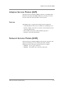
Adaptive Services Module (ASM) ................................................................................................4-5
Features ....................................................................................................................................4-5
Network Services Module (NSM) ...............................................................................................4-5
NSM-TX ...................................................................................................................................4-6
NSM-FX ...................................................................................................................................4-7
Features ....................................................................................................................................4-7
5
System Specifications
System Specifications ......................................................................................................................5-3
System Power Requirements .......................................................................................................5-4
ARX®6000 Hardware Installation Guide
vii
Table of Contents
Power Cord and Cable Requirements .......................................................................................5-5
Regulatory Compliance ................................................................................................................5-6
FCC Compliance .............................................................................................................................5-6
6
Unpacking and Installing the Chassis
Safety Instructions ...........................................................................................................................6-3
Required Tools and Equipment ...................................................................................................6-3
Verifying Shipment ..........................................................................................................................6-4
Unpacking the Chassis ...................................................................................................................6-5
Removing the Fan Tray ..................................................................................................................6-7
Removing the Power Supplies ............................................................................................6-7
Rack-Mounting the Chassis ...........................................................................................................6-9
Installing the Front Bezels .............................................................................................................6-9
Fan Tray ................................................................................................................................ 6-10
Utility Bay ............................................................................................................................. 6-10
Attaching the Power Cords ....................................................................................................... 6-11
Powering Up the Chassis ........................................................................................................... 6-12
Cabling the Modules .................................................................................................................... 6-13
Air Filter and Cable Management ............................................................................................ 6-13
Installing the Air-Filter Panel and Cable Guide ............................................................ 6-14
7
Connecting the Switch to the Network
Management Interfaces ..................................................................................................................7-3
Connecting the Console Terminal ..............................................................................................7-3
Booting the Switch ..........................................................................................................................7-4
Sample: Booting a Non-Replacement Switch ..................................................................7-4
Preparing for Switch Replacement .....................................................................................7-6
Installing a Redundant Peer or Cluster .............................................................................7-9
Sample: Replacing a Redundant Peer .............................................................................. 7-11
Connecting the Ethernet Management Port .......................................................................... 7-14
8
Maintenance
Powering Down the ARX®6000 .................................................................................................8-3
POST Diagnostics ...........................................................................................................................8-3
LED Status Indicators .....................................................................................................................8-5
Module Status LEDs ..............................................................................................................8-6
Ethernet-Port Link Status LEDs .........................................................................................8-7
Disk Drive LEDs ....................................................................................................................8-7
Fan Tray LEDs ........................................................................................................................8-7
A
Cable Connectors
ARX®6000 Connectors ................................................................................................................A-3
Console Connector and Pinouts ................................................................................................A-4
SFP Optical Connector .................................................................................................................A-5
B
Removing and Replacing FRUs
Before You Begin ........................................................................................................................... B-3
viii
Table of Contents
Removing and Replacing Modules .............................................................................................. B-3
Removing and Replacing a Disk Drive ...................................................................................... B-4
Silencing the RAID Alarm ................................................................................................... B-5
Replacing the Disk Drive .................................................................................................... B-6
Removing and Replacing the Fan Tray ...................................................................................... B-6
Removing and Replacing a Power Supply ................................................................................. B-7
Removing and Replacing the Air Filter ...................................................................................... B-7
ARX®6000 Hardware Installation Guide
ix
Table of Contents
x
1
Introduction
This manual describes F5’s Adaptive Resource Switch 6000 (ARX®6000)
and its hardware components. It also describes how to install the switch and
connect it to the network.
This chapter contains the following sections:
• Audience for this Manual
• Document Conventions
• Related Documents
• Safety and Regulatory Notices
• Contacting Customer Service
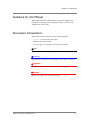
Audience for this Manual
Audience for this Manual
This manual is intended for field engineers and network administrators
responsible for setting up and connecting the switch to a network at the
enterprise data center facility.
Document Conventions
This manual uses the following conventions, when applicable:
• courier text represents system output
• bold text represents user input
• italic text appears for emphasis, new terms, and book titles
Note
Notes provide additional or helpful information about the subject text.
Important
Important notices show how to avoid possible service outage or data loss.
WARNING
Warnings are instructions for avoiding damage to the equipment.
DANGER
Danger notices help you to avoid personal injury.
ARX®6000 Hardware Installation Guide
1-3
Chapter 1
Introduction
Related Documents
In addition to this guide, the following F5 Data Solutions documentation is
also available:
•
ARX®6000 Quick Installation
• ARX®500 Hardware Installation Guide
• ARX®1000 Hardware Installation Guide
• ARX®2000 Hardware Installation Guide
• ARX®4000 Hardware Installation Guide
• ARX® GUI Quick Start: Network Setup
• ARX® CLI Reference
• ARX® CLI Network-Management Guide
• ARX® CLI Storage-Management Guide
• ARX CLI Maintenance Guide
1-4
Safety and Regulatory Notices
Safety and Regulatory Notices
Important
The ambient room temperature range that the unit can operate in is
5–35° C.
Important
Do not block power supply vents or otherwise restrict airflow when
installing unit in rack.
WARNING
Mechanical loading of rack should be considered so that the rack remains
stable and unlikely to tip over.
Class A ITE Label
This is a Class A product based on the standard of the Voluntary Control
Council for Interference by Information Technology Equipment (VCCI). If
this equipment is used in a domestic environment, radio disturbance may
occur, in which case, the user may be required to take corrective actions.
Qualified Personnel Warning
WARNING
Only trained and qualified personnel should be allowed to install, replace,
or service this equipment.
ATTENTION
Il est vivement recommandé de confier l'installation, le remplacement et la
maintenance de ces équipements à des personnels qualifiés et expérimentés.
ARX®6000 Hardware Installation Guide
1-5
Chapter 1
Introduction
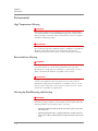
Environmental
High Temperature Warning
WARNING
To prevent the switch from overheating, do not operate it in an area that
exceeds the maximum recommended ambient temperature of 104° F (40° C).
To prevent airflow restriction, allow at least 3 inches (7.6 cm) of clearance
around the ventilation openings.
ATTENTION
Pour éviter une surchauffe du commutateur, ne pas le faire fonctionner dans
un local dont la température ambiante dépasse le maximum recommandé de
40 \xb0 C (104 F). Pour faciliter la circulation d'air, aménager un
dégagement d'au moins 7,6 cm (3 pouces) autour des bouches d'aération.
Restricted Area Warning
WARNING
This unit is intended for installation in restricted access areas. A restricted
access area is where access can only be gained by service personnel
through the use of a special tool, lock and key, or other means of security,
and is controlled by the authority responsible for the location.
ATTENTION
Cet appareil est à installer dans des zones d'accès réservé. Ces dernières
sont des zones auxquelles seul le personnel de service peut accéder en
utilisant un outil spécial, un mécanisme de verrouillage et une clé, ou tout
autre moyen de sécurité. L'accès aux zones de sécurité est sous le contrôle
de l'autorité responsable de l'emplacement.
Warning for Rack-Mounting and Servicing
WARNING
To prevent bodily injury when mounting or servicing this unit in a rack, you
must take special precautions to ensure that the system remains stable. The
following guidelines are provided to ensure your safety:
• This unit should be mounted at the bottom of the rack if it is the only
unit in the rack.
• When mounting this unit in a partially filled rack, load the rack from
the bottom to the top with the heaviest component at the bottom of the
rack.
1-6
Safety and Regulatory Notices
• If the rack is provided with stabilizing devices, install the stabilizers
before mounting or servicing the unit in the rack.
ATTENTION
Attention Pour éviter toute blessure corporelle pendant les opérations de
montage ou de réparation de cette unité en casier, il convient de prendre des
précautions spéciales afin de maintenir la stabilité du système. Les
directives ci-dessous sont destinées à assurer la protection du personnel:
• Si cette unité constitue la seule unité montée en casier, elle doit être
placée dans le bas.
• Si cette unité est montée dans un casier partiellement rempli, charger
le casier de bas en haut en plaçant l'élément le plus lourd dans le bas.
• Si le casier est équipé de dispositifs stabilisateurs, installer les
stabilisateurs avant de monter ou de réparer l'unité en casier.
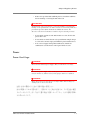
Power
Power Cord Usage
WARNING
Do not use the attached power supply cable for other devices or usage.
WARNING
The attached power supply cable was designed to be connected and to be
used for F5 devices, and the safety for this purpose has been confirmed.
WARNING
Please do not use it for other devices or usages. There may be danger of
causing a fire or an electric shock.
ARX®6000 Hardware Installation Guide
1-7
Chapter 1
Introduction
Electric Shock Warning
WARNING
This unit might have more than one power cord. To reduce the risk of
electric shock, disconnect the two power supply cords before servicing the
unit.
ATTENTION
Il est possible que cette unité soit munie de plusieurs cordons
d'alimentation. Pour éviter les risques d'électrocution, débrancher les deux
cordons d'alimentation avant de réparer l'unité.
SELV Circuit Warning
WARNING
The ports labeled LINK, 1/1 through 1/6, CONSOLE, MGMT, MIRROR,
and DEBUG are safety extra-low voltage (SELV) circuits. SELV circuits
should only be connected to other SELV circuits.
ATTENTION
Les ports étiquetés LINK, 1/1 through 1/6, CONSOLE, MGMT, MIRROR, et
DEBUG sont des circuits de sécurité basse tension (safety extra-low voltage
ou SELV). Les circuits SELV ne doivent être interconnectés qu'avec d'autres
circuits SELV.
Circuit Breaker (15A)
WARNING
This product relies on the building's installation for short-circuit
(overcurrent) protection. Ensure that a fuse or circuit breaker no larger
than 120 VAC, 15A U.S. (240 VAC, 10A international) is used on the phase
conductors (all current-carrying conductors).
ATTENTION
Pour ce qui est de la protection contre les courts-circuits (surtension), ce
produit dépend de l'installation électrique du local. Vérifier qu'un fusible ou
qu'un disjoncteur de 120 V alt., 15 A U.S. maximum (240 V alt., 10 A
international) est utilisé sur les conducteurs de phase (conducteurs de
charge).
1-8
Safety and Regulatory Notices
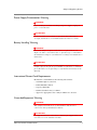
Power Supply Disconnection Warning
WARNING
Before working on a chassis or working near power supplies, unplug the
power cord on AC units.
ATTENTION
Avant de travailler sur un châssis ou à proximité d'une alimentation
électrique, débrancher lecordon d'alimentation des unités en courant.
Battery Handling Warning
WARNING
There is the danger of explosion if the battery is replaced incorrectly.
Replace the battery only with the same or equivalent type recommended by
the manufacturer. Dispose of used batteries according to the manufacturer's
instructions.
ATTENTION
Danger d'explosion si la pile n'est pas remplacée correctement. Ne la
remplacer que par une pile de type semblable ou équivalent, recommandée
par le fabricant. Jeter les piles usagées conformément aux instructions du
fabricant.
International Power-Cord Requirements
International cords should have the following characteristics:
• maximum length: 4.5 m/15 feet
• Female End: IEC-320-C13
• Capacity: 10A/250V
• Nominal Conductor size(s): 1.0mm2
• Approvals: Appropriate to the country in which it is to be used.
Grounded Equipment Warning
WARNING
This equipment is intended to be grounded. Ensure that the host is
connected to earth ground during normal use.
ATTENTION
Cet équipement doit être relié à la terre. S'assurer que l'appareil hôte est
relié à la terre lors de l'utilisation normale.
ARX®6000 Hardware Installation Guide
1-9
Chapter 1
Introduction
Laser Product Notice
WARNING
Class 1 laser product.
ATTENTION
Produit laser de classe I.
Class 1 lasers are defined as products which do not permit human access to
laser radiation in excess of the accessible limits of Class 1 for applicable
wavelengths and durations. These lasers are safe under reasonably
foreseeable conditions of operation.
WARNING
Do not stare into the beam or view the beam with optical instruments.
Harmonized IC Label Requirements: The following statement is applicable
to products that are intended for market in Canada under the harmonized
FCC-DOC EMI requirements. Equipment Requirements for units imported
into Canada shall bear both English and French translations as follows:
“This digital apparatus does not exceed the Class A or B limits for radio
noise emissions from digital apparatus set out in the Radio Interference
Regulations of the Canadian Department of Communications.
This Class A or B digital apparatus complies with ICES-003
“Le present appareil numerique n'emet pas de bruits radioelectriques
depassant les limites applicables aux appareils numeriques de la class A
prescrites dans le Reglement sur le brouillage radioelectrique edicte par
le ministere des Communications du Canada.'1
Cet appareil numerique de la classe A or B est conforme a la norme
NMB-003 du Canada.
1 - 10
Contacting Customer Service
Contacting Customer Service
You can use the following methods to contact F5 Networks Customer
Service:
F5 Networks Online
Knowledge Base
http://support.f5.com
Online repository of answers
to frequently-asked questions.
F5 Networks Services
Support Online
https://websupport.f5.com
Online customer support
request system
Telephone
Follow this link for a list of Support
numbers:
http://www.f5.com/training-support/cust
omer-support/contact/
ARX®6000 Hardware Installation Guide
1 - 11
Chapter 1
1 - 12
2
Product Overview
This chapter provides a general overview of the F5 ARX®6000. Topics
include the following:
• The ARX®
• Redundancy Features
• Switch Management
• Supported Protocols
The ARX®
The ARX
®
The Adaptive Resource Switch (ARX®) 6000 is a 6-slot switch for use in
large data centers and regional data centers. The switch enables enterprises
to globally access, manage, deliver and optimize information resources. The
ARX® aggregates multiple disparate storage into a unified global file
system, eliminating stranded capacity and employing intelligent policies to
optimize costly storage resources. The switch performs this aggregation
across different storage-access protocols, classes of storage, physical
locations, and multi-vendor equipment.
The switch optimizes file storage and server capacity and simplifies
resource management. Because it resides in the data path, the switch is
aware of attached storage, server, and network resources and how they are
used. It then dynamically adapts the infrastructure to meet user demands.
The switch consists of a 6-slot chassis that accommodates a system
management and control module and a family of service modules that
support Fast Ethernet and Gigabit Ethernet interfaces for connectivity to
network infrastructure, network-attached storage (NAS) devices, and file
servers with direct-attached storage (DAS).
The switch’s 80-Gbps aggregate switching capacity ensures non-blocking
throughput for all modules in the system. The switch also provides
high-speed TCP and Secure Sockets Layer (SSL)/IPsec offload capability.
The switch is highly available, providing module-level redundancy,
switch-to-switch redundancy, redundant power, and RAID Level 1
mirroring technology. In addition, all field replaceable units (FRUs) in the
system are hot-swappable.
The ARX® has a secure and reliable mechanism for switch-to-switch
communications in order to provide switch redundancy and to provide
transparent access to distributed file storage resources. This site-to-site
communication network is established through a Resilient Overlay Network
(RON) tunnel, which is configured over an existing IP infrastructure.
ARX®6000 Hardware Installation Guide
2-3
Chapter 2
Product Overview
Redundancy Features
The ARX®6000 system is designed to provide a highly available service
with fault tolerance and no single point of failure. This design provides the
following features:
• High availability (HA) clustering for switch redundancy, including
intra-box (modules) and inter-box (redundant-pair) failover capability:
• For multiple NSMs in a single chassis, if a one fails the other provides
connectivity for all other modules.
• For two switches in a redundant pair, one switch starts as primary and the
other switch starts as secondary. If a module in the primary switch fails,
the switch “fails over” to the secondary switch.
• Redundant Array of Independent Disks (RAID) Level 1 protected
boot/configuration disk drives.
• Redundant power supplies installed share the power load.
• Redundant connections to the fan tray.
• Redundant AC/DC power.
See Chapter 3, Chassis Hardware, for more information about these chassis
components.
Switch Management
For local and remote management, the ARX®6000 provides the following
management interfaces:
• one serial-console port (labeled “Console”),
• one out-of-band 10/100 Ethernet port (labeled “MGMT”), and
• a configurable number of inband Ethernet interfaces.
See Chapter 7, Connecting the Switch to the Network, for information about
bringing the out-of-band MGMT port online after initial boot-up.
See the ARX® CLI Network-Management Guide and ARX® CLI Reference
for information about configuring the in-band interfaces.
2-4
Supported Protocols
Supported Protocols
The ARX® supports a range of network, application, and file-access
protocols, including the following:
• Layer 2 and layer 3 network protocols
• Common management protocols
• Security and file service protocols for data encryption, exchange,
backup/restore, and storage management
Network
• 802.1D and Rapid Spanning Tree
Note
In 802.1D mode, the switch executes the 802.1S protocol in 802.1D
compatibility mode. This allows inter operability with legacy 802.1D-only
devices.
• VLAN (802.1Q)
• passive link aggregation (802.3ad), without LACP
• Internet Protocol (IP)
• Transmission Control Protocol/User Datagram Protocol (TCP/UDP)
• Domain Name Service (DNS), as a client
• Network Time Protocol (NTP), as a client
File Services
• Common Internet File System (CIFS)
• Network File System (NFS): NFSv2 over UDP and NFSv3 over TCP or
UDP
• Network Locking Manager (NLM)
Security and Authentication
• NT LAN Manager (NTLM) v1
• NT LAN Manager (NTLM) v2
• Network Information Service (NIS, also known as YP)
• Kerberos authentication for Windows clients
• Remote Authentication Dial-In User Service (RADIUS) for
administrators
ARX®6000 Hardware Installation Guide
2-5
Chapter 2
Product Overview
Management
• Simple Network Management Protocol (SNMP)
• TELNET
• SSH (Secure SHell)
• Hypertext Transfer Protocol (HTTP)
• Hypertext Transfer Protocol over SSH (HTTPS)
• SOAP-based API over HTTP and/or HTTPS
• For transferring maintenance and release files:
– File Transfer Protocol (FTP)
– Trivial File Transfer Protocol (TFTP)
– Secure Copy (SCP)
– NFS, for transfers to or from an ARX volume
– CIFS, for transfers to or from an ARX volume
– Simple Mail Transfer Protocol (SMTP), for sending email notices of
trouble conditions
2-6
3
Chassis Hardware
This chapter describes the switch chassis components and hardware
configuration.
Topics include the following:
• Chassis Components
• Chassis Configurations
• Redundant Pairs
• Resilient Overlay Network (RON)
This chapter describes chassis hardware only. For information about
hardware modules (management and service modules), see Chapter 4,
Hardware Modules.
Chassis Components
Chassis Components
The F5 ARX®6000 is a 6-slot chassis that mounts into a standard 19-inch
rack. The first slot is reserved for switch management, control, and
switch-fabric functions. The remaining five slots support interchangeable
installation of I/O service modules.
• Slot 1 is reserved for the System Control Module (SCM) which provides
switching and management functions.
• Slots 2 through 6 are available for all service modules in a system
configured for 220V power.
• All modules are field-replaceable.
The chassis is shipped with all components installed per customer order.
Components include all management and service modules, power supplies,
disk drives, and fan tray (includes six fans).
The chassis utility bay accommodates two system disk drives and up to two
power supplies.
Figure 3.1 Chassis Front View
Fan tray (houses 6
fans)
SCM management
module (slot 1)
Service modules in any
of slots 2–6
Power Supply
The switch is powered by one or two fully managed AC/DC power supplies.
Two power supplies are recommended for full redundancy and load-sharing.
Each power supply provides the following:
ARX®6000 Hardware Installation Guide
3-3
Chapter 3
Chassis Hardware
• 1500 W @ 220 Vac (Note: the system draws 1704 W from the power
cord due to the less-than-100% efficiency of the power supplies.)
• -48 Vdc output power
• Load sharing between two power supplies
• Separate AC line power cord for each power supply unit
• Separate AC Fail and DC Fail fault indicators per power supply unit
• Power Fail and over-temperature alarms displayed on system console
• Hot swappable and front accessible components
See for power requirements and specifications.
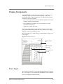
Figure 3.2 Disk Drive and Power-Supply Locations
Disk Drives
D1 (LUN1)
D2 (LUN2)
Power Supplies
PS1
PS2
Disk Drives
The switch requires two system disk drives for operation. Together the two
disk drives provide RAID Level 1 redundancy. The drives contain software
images, reports, scripts, log files, and configuration files.
3-4
Chassis Components
The disk drives are connected through a SCSI bus to the System Control
Module (SCM) in the chassis. The dual-channel SCM communicates over
two separate buses to the disk drives in bay shelves D1 and D2. Figure 3.3
shows the SCM-to-drive interconnections.
Figure 3.3 Dual-Channel Internal Drive Connections
Backplane
SCM
SCSI
Controller
Shelf D1
Disk 1
A
B
Shelf D2
Disk 2
Logical Unit Numbers (LUNs)
Each system drive has a logical unit number (LUN) (address 1 and 2)
corresponding to bay slot 1 (D1) and bay slot 2 (D2). Dual-channel drives
are mapped to LUNs 1 and 2. LUNs enable multiple drives to be
“daisy-chained” to a single controller. The LUN address identifies the drive
so that the controller can send the correct data to the correct drive(s).
Status LEDs
The disk drives provide three status LEDs:
• Red — indicates Activity
• Green — indicates Power
• Orange — indicates Failure
Fan Tray Module
The chassis fan tray module is an environmentally controlled fan system
with an intelligent fan controller. The fan tray contains six individual fans
and is located at the top of the chassis (refer back to in Figure 3.1 on
page 3-3).
The “hot-pluggable” fan tray (containing six fans) is a field replaceable unit
(FRU) that can be replaced without service interruption. See Appendix B,
<Emphasis>Removing and Replacing FRUs for information about
removing/replacing FRUs.
The SCM has redundant connections to the fan tray module for temperature
control and status monitoring. It communicates with the fan tray module at
regular 60-second intervals.
Features
The fan tray module provides the following features:
• Fan speed controlled through a pulse modulated input to the fan
ARX®6000 Hardware Installation Guide
3-5
Chapter 3
Chassis Hardware
• Fan speed controlled by SCM in response to temperature fluctuations in
the chassis
• Fan tachometer monitors revolutions per minute (RPM)
• Closed-loop system monitors temperature conditions in the chassis with
a return to the fan system; this causes airflow to increase or decrease, as
required, to maintain the proper temperature within the chassis
• Two LEDs on the fan-tray front panel indicate operational status (see
Chapter 8, Maintenance for LED descriptions)
• Failure indications include:
• Single fan failure
• Multiple fan failure
• Low/high RPM on any fan
• High temperature
• Lost SCM-to-fan tray communication
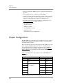
Chassis Configurations
The ARX®6000 can accommodate up to six modules in its chassis, and these
modules can be configured to maximize throughput or to maximize high
availability between switches.
The switch currently supports one management module (SCM) in slot 1 and
service modules (NSM and ASM) in any order (or combination) in the
service module slots. Most configurations require at least one NSM for
network connectivity and one ASM for adaptive services. See Chapter 4,
Hardware Modules for information about the individual ARX®6000
modules.
Table 3.1 describes the basic and maximum capacity ARX®6000 chassis
configurations.
Basic System
Slot
Maximum Capacity
Module
Slot
1
SCM
2
ASM
3
3
ASM
4
4
ASM
5
5
NSM
6
6
NSM
1
SCMa
2
Service Modules
b
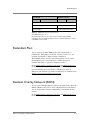
Table 3.1 ARX®6000 Chassis Configurations
3-6
Module
Redundant Pairs
Basic System
Slot
Maximum Capacity
Module
Slot
Module
Utility Bay
2 disk drives: D1, D2
2 disk drives: D1, D2
2 power supplies
2 power supplies: PS1, PS2
Table 3.1 ARX®6000 Chassis Configurations
a.The SCM always uses slot 1.
b.Service modules may use any of slots 2–6. For in-chassis high availability,
redundant modules are installed in adjacent slots, for example, ASMs in slots 3 and
4, and NSMs in slots 5 and 6.
Redundant Pairs
You can purchase two ARX®6000 switches and configure them as a
redundant pair. If the primary switch fails, all services “fail over” to the
secondary switch. This is a highly-available configuration.
The redundant switches are interconnected through one or more of their
Gigabit Ethernet ports. You use the CLI to configure the ports for
redundant-link traffic (as opposed to client/server traffic).
See the ARX® CLI Network-Management Guide and ARX® CLI Reference
for information about configuring redundant switches.
If you are installing the second switch in a redundant pair, there are
differences in the initial-boot procedure. The differences are outlined later in
Chapter 7, Connecting the Switch to the Network.
Resilient Overlay Network (RON)
You can connect multiple ARX®es together in a Resilient Overlay Network
(RON). A RON is composed of a series of IP tunnels between the switches.
You can use the CLI to configure a RON tunnel, as described in the CLI
manuals.
See the ARX® CLI Network-Management Guide and ARX® CLI Reference
for information about configuring RON tunnels.
ARX®6000 Hardware Installation Guide
3-7
Chapter 3
Chassis Hardware
3-8
4
Hardware Modules
This chapter describes the switch modules, including their hardware
features, functions, and front panel interfaces. For information about module
connectors and pinout assignments, see Appendix A, Cable Connectors.
ARX®6000 modules include the following management and service
modules:
• System Control Module (SCM)
• Adaptive Services Module (ASM)
• Network Services Module (NSM)
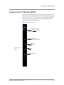
System Control Module (SCM)
System Control Module (SCM)
The System Control Module (SCM) provides the management and control
functions for the other modules in the chassis. The SCM communicates with
the slots in the chassis over a system status bus, which enables the SCM to
manage, monitor, and control module activity. The SCM also provides
switch fabric functionality in the chassis.
Figure 4.1 SCM Front Panel
Alert and Status LEDs
(See Chapter 8 for LED
information.)
10/100 Ethernet
management port (RJ-45)
Mirror port
(RS-232)
Serial console port
(RJ-45)
Link status LEDs
ARX®6000 Hardware Installation Guide
4-3
Chapter 4
Hardware Modules
Features
The SCM provides or supports the following features and functions:
Switch Fabric
• Non-blocking architecture for 40-Gbps full duplex non-blocking
aggregate throughput
• 10-Gbps full duplex throughput for each service module slot
• Switch control-plane and data-plane functions
• 9K jumbo frames
Chassis Management
• RS232/Console serial interface for local switch management
• 10/100 Management Ethernet interface for local/remote switch
management
• Mirror port for monitoring and troubleshooting user ports
• Service definition and policy enforcement
• MAC-address assignment for modules
• Real-time clock synchronization for modules
• Gathering and monitoring of module health status and statistics through
LEDs and software
• Module insertion/removal in a slot
Environmental Control and Management
The SCM also manages or monitors the following functions:
• Temperature changes in the chassis and for each module
• Module resets (for example, if a module’s temperature gets too high) or
power-down operation
• Power draw for each module
• Fan tray control interface
Dual-Channel SCM
The SCM’s dual-channel bus architecture enables it to communicate over
two separate buses to the system disk drives. This configuration provides an
additional level of redundancy by providing a second SCSI bus and permits
each SCSI drive to be connected to the SCM in slot 1. For more information
about the SCM and its bus interconnections, see Disk Drives, on page 3-4.
4-4
Adaptive Services Module (ASM)
Adaptive Services Module (ASM)
The Adaptive Services Module (ASM) provides the core distributed filer
functions for the switch. The ASM module has no external ports. It does
provide external Alert and Status LEDs on the front panel.
Features
The ASM provides or supports the following features and functions:
• Virtual distribution of file services for NFS v2/v3 and CIFS protocols
• Dynamic adapting of the directory structure of back-end filers based on
data management policies
• Back-end file storage device (NAS and DAS) aggregation
• Namespace and volume management
Network Services Module (NSM)
The Network Services Module (NSM) provides network connectivity and
supports load balancing, resource switching, Fast Path, and VPN
terminations for the switch. Two standard versions are available:
• NSM-TX — 6-port copper connections
• NSM-FX — 6-port fiber-optic connections, multi-mode
ARX®6000 Hardware Installation Guide
4-5
Chapter 4
Hardware Modules
NSM-TX
Figure 4.2 shows the NSM-TX module front panel, which provides six
RJ-45 connections.
Figure 4.2 NSM-TX Front Panel
Alert and Status LEDs
(See Chapter 8 for LED
information.)
Ports 1–6, Link status LEDs
Ports 1– 6, RJ-45 connectors
4-6
Network Services Module (NSM)
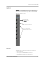
NSM-FX
Figure 4.3 shows the NSM -FX module front panel, which provides six
small form-factor pluggable (SFP) optical connectors, 850nm multi-mode.
These connectors can reach distances up to 500m over 50/125um MMF.
Figure 4.3 NSM-FX Front Panel
Alert and Status LEDs
(See Chapter 8 for LED
information.)
Ports 1 – 6, Ethernet port Link status
LEDs
Ports 1 – 6 , small form-factor
pluggable (SFP) optical connectors
Features
The NSM provides or supports the following features and functions:
• Network connectivity
• Auto-negotiation for 100/1000 Ethernet transmission
• Standard Ethernet and jumbo-frame (9K) packet sizes
ARX®6000 Hardware Installation Guide
4-7
Chapter 4
Hardware Modules
• Full-duplex switching at line rates for Layer 2 processing
• Low latency, store and forward switching, with built-in multicast support
• Resource switching
• Network File System (NFS) fast path
• Common Internet File System (CIFS) fast path
• NFS-client connection aggregation to direct network-attached storage
(NAS)
4-8
5
System Specifications
This chapter describes technical system specifications, power requirements,
and cable requirements for the ARX® and its components. This chapter also
describes regulatory information.
Topics include:
• System Specifications
• System Power Requirements
• Power Cord and Cable Requirements
• Regulatory Compliance
• FCC Compliance
See Appendix A for cable-connector diagrams and pinouts.
System Specifications
System Specifications
Table 5.1 describes the ARX® system specifications.
Component
Specification
Chassis Dimensions
Height: 22.75 in.
(includes fan tray and front bezel)
Width: 19.00 in. (including the fixed mounting ears)
Depth: 23.00 in.
Chassis Weight
(includes fan tray, 2 disk drives,
1 power supply, 3 modules)
150 lb (68.04 kg)
Chassis / Power Supply
Altitude: -200 ft. (-60 m) min. to 8000 ft. (2500 m) max.
Environmental Requirements
Humidity —
Operating: 5 % min. to 95% max. (non condensing)
Storage: 5% to 95%
Temperature —
Operating: 32 deg. to 104 deg. F (0 deg. to 40 deg. C)
Storage: -40 deg. to 149 deg. F (-20 deg. to 65 deg. C)
Power Supply Power
Input voltage: 220 Vac
Output voltage: -48 Vdc
3000 W maximum total DC power per chassis (Note: only 1500 W power is
used; the 3000 W accounts for redundant power supplies. Due to the 88%
efficiency of the drives, 1704 W input is required to achieve the maximum
1500 W output.)
Fan Tray Dimensions (includes
outer bezel)
Height: 4.88 in. (12.40 cm)
Width: 17.25 in. (43.82 cm)
Depth: 18 in. (45.72 cm)
Fan Tray Power
Input voltage: 48 Vdc (6 fans)
Max. input current: 4 A
Airflow Clearance
Air Filter
Minimum clearance of 12 inches (30.48 cm) required for air intake from
bottom front of chassis and exit through the top back (and side) of chassis to
maintain proper venting and prevent overheating.
Height: 0.25 in. (0.635 cm)
Width: 11 in. (27.94 cm)
Depth: 20 in. (50.8 cm)
Table 5.1 System and Module Specifications
ARX®6000 Hardware Installation Guide
5-3
Chapter 5
System Specifications
Component
Specification
Hardware module dimensions (SCM,
ASM, NSM)
Height: 15.25 in. (38.74 cm)
Width: 1.75 in. (4.45 cm)
Depth: 20 in. (50.8 cm)
Input voltage: -48 Vdc
Hardware module power
(SCM, ASM, NSM)
(See Table 5.2 for power
consumption information.)
Table 5.1 System and Module Specifications (Continued)
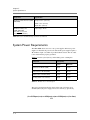
System Power Requirements
The ARX®6000 chassis uses one or two power supplies. When two power
supplies are installed, the power load is shared. The power supplies require a
20 A/220 Vac input cord, which is provided with the chassis. The AC outlet
to the switch must be properly grounded.
Table 5.2 lists the system (fan tray and modules) power consumption.
Component
Power (Watts)
Typical
Maximum
System Control Module (SCM)
160 W
179 W
Network Services Module (NSM)
125 W
137 W
Adaptive Services Module (ASM)
210 W
237 W
Fan Tray (6 fans + fan controller)
105 W
176 W
Table 5.2 Module Power Consumption
The total power dissipated by the chassis is the sum of all of the above
divided by 0.88 (the power supply runs at 88% efficiency). Specifically,
(------------------------------------------------------------------------------------------------------------------------------------------------------------------1 × SCMpwr ) + ( n × ASMpwr ) + ( m × NSM pwr ) + ( 1 × fans )0.88
5-4
Power Cord and Cable Requirements
Where
n is the number of installed ASMs
m is the number of installed NSMs
The division by 0.88 accounts for the 88% efficiency of the power
supply.
If you want to plan for future expansion, you can budget for a total of 1704
Watts power dissipation. This is equivalent to 5812 BTUs/hour.
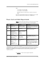
Power Cord and Cable Requirements
Table 5.3 lists the required cables and power cords for the switch. All cables
except the AC power cord and console cable are customer-supplied.
Qty.
Cable/Cord
Used on...
Specification
1 per power
supply
AC power cord
AC/DC Power Supply
L6-20 type connectors for systems rated
at 20 A/220 Vac
1
Console cable with
RJ-45-to-DB9 adapter
Console port
100BASE-T Category 5 unshielded
twisted pair (UTP); 24 AWG
2
Ethernet cables for
connection to
10/100 Mbps Ethernet
management port (RJ-45
connector);
System Control Module
(SCM)
Ethernet cables for
connection to 100/1000
Mbps Ethernet.
6-port Network Services
Module (NSM)
(copper version)
a100/1000BASE-T
6-port NSM (optical
version)
100BASE-FX (fast Ethernet)/
1000BASE-SX (Gigabit Ethernet), 850nm.
Short-reach multi-mode fiber (MMF) with
duplex LC-style connectors. Distances up
to 500m on 50/125um MMF, or 300m on
62.5/125um MMF.
6 per NSM
MGMT port
Mirror port
Category 5/6,
unshielded twisted pair (UTP) cable; 24
AWG
(RJ-45 connectors)
6 per NSM
Fiber-optic cable for
connection to 1-Gbps
Ethernet.
small form-factor
pluggable (SFP) optical
connectors
Table 5.3 Required Power and Data Cables
a.NSM Gigabit Ethernet ports support automatic MDI/MDIX cross-over. This feature automatically corrects the polarity of
the attached CAT5 cable, regardless if it is a cross-over or straight-through type. However, for this feature to work, the port
speed must be set to auto (auto-negotiate) through the CLI. When the port speed/duplex is forced (auto-negotiate is
disabled), automatic MDI/MDIX cross-over is disabled, and you must cable the port using standard cross-over or
straight-through cabling.
See Appendix A for cable-connector diagrams and pinouts.
ARX®6000 Hardware Installation Guide
5-5
Chapter 5
System Specifications
Regulatory Compliance
The ARX®6000 switch complies with the following agency requirements:
Category
Compliance
Safety
UL 60950
cUL listed to CSA C22.2 No. 950
IEC950 (EN60950) CE Marking
Emissions
FCC Part 15 Class A
CISPR22 Class A (EN55022) CE Marking
EN 55024
VCCI Class A
FCC Compliance
Important
This is a Class A product. In a domestic environment this product may cause
radio interference, in which case the user may be required to take adequate
measures.
Changes or modifications not expressly approved by the manufacturer could
void the user’s FCC granted authority to operate this equipment.
Note
This equipment has been tested and found to comply with the limits for a
Class A digital device, pursuant to part 15 of the FCC Rules. These limits
are designed to provide reasonable protection against interference when the
equipment is operated in a commercial environment. This equipment
generates, uses, and can radiate radio frequency energy and, if not installed
and used in accordance with the instruction manual, may cause harmful
interference to radio communications. Operation of this equipment in a
residential area is likely to cause harmful interference in which case the
user will be required to correct the interference at his own expense.
5-6
6
Unpacking and Installing the Chassis
This chapter describes the following topics and tasks:
• Safety Instructions
• Required Tools and Equipment
• Verifying Shipment
• Unpacking the Chassis
• Removing the Fan Tray
• Rack-Mounting the Chassis
• Installing the Front Bezels
• Attaching the Power Cords
• Powering Up the Chassis
• Cabling the Modules
• Air Filter and Cable Management
Safety Instructions
Safety Instructions
Observe the following safety guidelines to avoid personal injury or damage
to equipment when installing or operating the switch:
DANGER
The chassis is both heavy and difficult to maneuver. Two or more people are
required to move and lift the chassis.
DANGER
Never assume that power is disconnected from a circuit; always check.
Before installing the switch, locate the power ON/OFF toggle on the back of
the chassis and make sure it is set to OFF.
Disconnect any power or external cables before moving a chassis.
A chassis configured with two power supplies has two power cords. In the
event that AC power must be removed from the system, disconnect both
power cords before servicing the unit to avoid electric shock.
Required Tools and Equipment
The following equipment is required/recommended for unpacking,
rack-mounting, and installing the chassis:
• pallet jack or handcart
• Wire cutter/utility knife
• Rack-mount screws
• #2 Phillips screwdriver
• Flat-head screwdriver
• Data cables (see Power Cord and Cable Requirements, on page 5-5)
• Customer-supplied standard 19-inch EIA rack
• Antistatic wrist straps for handling modules
ARX®6000 Hardware Installation Guide
6-3
Chapter 6
Unpacking and Installing the Chassis
Verifying Shipment
The ARX®6000 shipment includes:
• Chassis and hardware components
• Accessory kit
Check the contents of the shipping crate and any additional boxes to verify
complete shipment. Table 6.1 lists the contents you should receive.
Box/Crate
Contents
Chassis
ARX®6000 chassis with installed components:
fan tray, modules, two power supplies, two disk drives, air
filter/cable guide
Accessory Kit
Front bezels (cover fan tray and utility bay)
2 20A 250V power cords
Console cable (8 ft.) with RJ-45-to-DB9 adapter
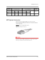
Keys for unlocking disk drives
Air-filter front panel/cable guide
ARX®6000 rack-mount-alignment template (long, white
stickers)
ARX®6000 Quick Installation card
ARX®6000 Hardware Installation Guide (this manual)
Table 6.1 Verify Shipping-Crate Contents
6-4
Unpacking the Chassis
Unpacking the Chassis
The chassis is shipped with all ordered components installed. The chassis
shipping carton is attached to a reinforced pallet for easy transfer (using a
handcart or pallet jack) to the installation site. The accessory kit is packaged
with the chassis.
Figure 6.1 Chassis Shipping Carton
Unpack the chassis as follows:
1. Using a handcart or pallet jack, move the shipping carton to the
installation site.
DANGER
With packaging, a minimally-configured chassis weighs approximately 163
lb (150 lb without packaging). Two or more people are required to move,
lift, and rack-mount the chassis.
2. Before unpacking the chassis, inspect the carton for any shipping
damage.
3. Using a wire cutter, cut and remove the package strapping from the
shipping carton.
4. Remove the carton top cover and open the box.
ARX®6000 Hardware Installation Guide
6-5
Chapter 6
Unpacking and Installing the Chassis
5. Remove the small box inside. This contains the accessories
described in Table 6.1.
6. Slowly slide/lift the outer carton up and away from around the
chassis, which sits in foam packaging on the pallet.
7. Remove the foam packaging from the bottom front and back of the
chassis.
Before you install the chassis into a rack, it is recommended that you remove
the fan tray and power supplies to facilitate handling and ease
rack-mounting. These components are particularly heavy. You can replace
these units after the chassis is secured in the rack, as shown in the next
section.
6-6
Removing the Fan Tray
Removing the Fan Tray
The fan tray is accessible from the front of the chassis. It is located at the top
of the switch.
1. Loosen the captive screws on either side of the fan tray, grasp the
handle, and slowly pull the fan tray toward you (see Figure 6.2).
Figure 6.2 Removing Fan Tray
captive screws
2. Carefully slide the fan tray out of the top of the chassis and set
aside.
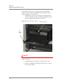
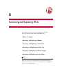
Removing the Power Supplies
The chassis contains two power supplies that are accessible from the front
panel. The top power supply is called power supply “A” in the CLI’s show
chassis chassinfo command. The bottom power supply is power supply “B.”
ARX®6000 Hardware Installation Guide
6-7
Chapter 6
Unpacking and Installing the Chassis
Power Supply A (the top one) corresponds to the power plug labeled
“Primary” on the back panel. Power Supply B corresponds to the plug
labeled “Redundant” on the back panel.
1. In the utility bay, remove a power supply by carefully inserting a
flat-head screwdriver into the center notch and pulling up and out.
The power supply handle will release toward you.
Figure 6.3 Removing the Power Supply
handle-release notch
pull
handle
slowly
WARNING
Do not put excessive strain on the handle. Do not lift or carry the power
supply by its handle.
2. Carefully slide the power supply out of the bay and set aside.
3. If there is a redundant power supply, repeat these steps to remove
the other power supply.
6-8
Rack-Mounting the Chassis
Rack-Mounting the Chassis
An EAI standard rack has holes that you must align with the holes in the
chassis flange. A set of ARX®6000 rack-mount-alignment templates are
included in the accessory kit to help with this alignment. These are long,
white stickers with holes in the same pattern as the chassis flange. Line them
up with the holes in the rack to create a visual target for the chassis.
With one person in the front of the chassis and another at the back, carefully
lift the chassis into the rack and align the six holes on each side of the
chassis (flange edges) with the holes in the rack. See Figure 6.4. Use the
alignment templates as a guide.
Figure 6.4 Aligning Chassis Flange with Rack
Align chassis flanges with rack - secure with 6 screws on each side
1. Insert 1-inch (2.5 cm) Phillips-head screws (six on each side)
through the holes and tighten securely.
2. When the chassis is secured in the rack, replace the fan tray and
power supply (or power supplies). Reverse the steps in Removing
the Fan Tray, on page 6-7 and Removing the Power Supplies, on
page 6-7.
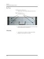
Installing the Front Bezels
After you have reinstalled the fan tray and power supplies in the chassis, you
can install the front bezels over the fan tray and utility bay. The bezels are
shipped in the accessory kit.
ARX®6000 Hardware Installation Guide
6-9
Chapter 6
Unpacking and Installing the Chassis
Fan Tray
To install the bezel over the fan tray:
1. Align the clips (on back of bezel) with the pins on the fan tray.
Figure 6.5 Fan Tray Bezel
Bezel Pins (2 each side)
2. Using two hands, gently press the bezel squarely onto the pins until
the bezel clicks into place over the fan tray.
Utility Bay
1. Align the bezel over the utility bay, holding the bezel by the
indentation on the left side for an easier grip.
6 - 10
Attaching the Power Cords
2. Align the clips (on back of bezel) with the pins at the top and
bottom on the utility bay.
Bezel Pins
(upper and lower,
2 each side)
3. Gently push the bezel down over the pins until it clicks into place
top and bottom.
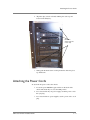
Attaching the Power Cords
To attach the AC power cords to the chassis:
1. Locate the power ON/OFF toggle switches on the back of the
chassis and ensure they are set to the OFF position.
2. For a chassis with only one power supply, attach the power cord to
the right plug.
3. For a chassis with two power supplies, attach a power cord to each
plug.
ARX®6000 Hardware Installation Guide
6 - 11
Chapter 6
Unpacking and Installing the Chassis
The right plug, labeled “Primary,” connects to the top power supply.
This is called power supply “A” in the CLI’s show chassis command.
The left plug, labeled “Redundant,” connects to the bottom power
supply. The bottom power supply is power supply “B.”
DANGER
A chassis configured with two power supplies has two power cords. In the
event that AC power must be removed from the system, disconnect both
power cords before servicing the unit. Otherwise, there is a risk of electric
shock.
Figure 6.6 Power Switch and Connections
For chassis with a single power supply, use the right power plug
See Power Cord and Cable Requirements, on page 5-5 for power cord and
cable specifications.
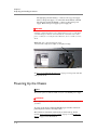
Powering Up the Chassis
Note
The switch requires a dedicated 20A circuit for each AC/DC power supply.
WARNING
Before applying power, ensure that the AC outlet to the switch is properly
grounded.
To power up the chassis, find both ON/OFF toggle switches on the back
panel. Flip both switches to the ON position.
The switch boot wizard runs automatically at switch start-up. See the
sections, Connecting the Console Terminal, on page 7-3 and Booting the
Switch, on page 7-4 for information.
6 - 12
Cabling the Modules
Once initial boot-up has occurred, the fan speed automatically regulates for
the appropriate cooling requirement based on ambient temperature.
Cabling the Modules
You can cable the modules before or after the switch is connected to the
network. For console connection and switch-boot information, see Chapter
7, Connecting the Switch to the Network.
Module cables (except the console cable) are supplied by the customer. For
cable specifications and requirements for each of the module types, see
Power Cord and Cable Requirements, on page 5-5. describes cable
connector and pinout information.
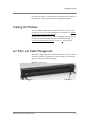
Air Filter and Cable Management
The chassis is shipped with the air filter installed. The accessory kit contains
the air filter panel/cable guide which covers the air filter tray and provides
guides at each end for cable management.
Figure 6.7 Cable Guide
Captive Screw
ARX®6000 Hardware Installation Guide
Captive Screw
6 - 13
Chapter 6
Unpacking and Installing the Chassis
Figure 6.8 shows the air filter and cable guide location on the bottom front
of the chassis.
Figure 6.8 Air Filter/Cable Guide Location
Air filter and cable guide location
Installing the Air-Filter Panel and Cable Guide
WARNING
Customers are required to maintain the switch’s air filter at regular
intervals. Failure to do so may damage the switch.
To install the air-filter panel/cable guide:
1. Remove the air-filter front panel/cable guide from the accessory kit.
2. Remove the tape from the air filter opening and verify the air filter
is seated properly in the chassis.
3. Insert the cable guide into the opening, aligning the captive screws
on either side with the holes in the chassis.
4. Hold one side while tightening the screw on the opposite side; then
tighten the other screw to secure the cable guide in place.
6 - 14
7
Connecting the Switch to the Network
This chapter describes how to connect the ARX® to a console terminal and
boot the switch for the first time.
Topics and tasks include:
• Management Interfaces
• Connecting the Console Terminal
• Booting the Switch
• Connecting the Ethernet Management Port
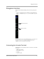
Management Interfaces
Management Interfaces
The System Control Module (SCM) provides the following management
ports:
• Console - a serial Console port for connecting a console terminal, and
• MGMT - a 10/100 Ethernet port for an out-of-band (OOB) management
station.
OOB management (RJ-45)
serial Console (RJ-45)
During the initial-boot process described in this chapter, you can only access
the serial Console port. You configure the OOB management port
(“MGMT”) as part of the procedures in this chapter.
Connecting the Console Terminal
Set the following console-terminal parameters to match those on the SCM’s
Console port:
• 9600 baud rate (default)
• XON-XOFF flow control
• 8 data bits
• 1 stop bit, no parity
ARX®6000 Hardware Installation Guide
7-3
Chapter 7
Connecting the Switch to the Network
Connect the console terminal to the serial Console port (RJ-45) on the SCM.
An RJ-45 to DB9 adapter is included in the installation kit if you want to
connect to your management station’s serial DB9 port.
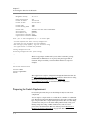
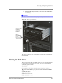
Booting the Switch
The initial-boot script runs automatically at switch start-up. It prompts for
basic configuration and security information required to access the switch
and manage it remotely.
At the console terminal, boot the switch as follows:
1. Power-on the switch (as shown in Powering Up the Chassis, on
page 6-12). After some boot-up messages, the following prompt
appears:
Press <Enter> to start the Switch Configuration Wizard.
2. Press <Enter> as prompted.
Several questions appear, prompting you for basic network information
(such as management-IP address, mask, and gateway). These questions
comprise the initial-boot script. Answer these questions as they come up.
Examples and instructions appear in the subsections below.
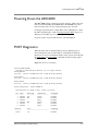
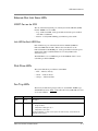
Sample: Booting a Non-Replacement Switch
This sample shows the simplest initial-boot scenario, for a new
(non-replacement) switch that is either standalone or the first member of a
redundant pair. The sample answers are not necessarily appropriate to the
following scenarios:
• this replaces a defunct switch,
• this will join a running switch as its redundant peer, or
• this switch is being re-installed after F5 personnel performed a
“Manufacturing Installation” on a previously-running switch.
Later sections discuss these contingencies and how to handle each of them.
The answers below apply to the simplest case only. Sample answers are
shown in bold text:
F5 ARX Switch Startup
This F5 ARX switch does not currently have critical system
information programmed. The following wizard prompts you
for this information. You can connect to the switch through
the out‐of‐band management interface when you finish.
To restart the configuration program, enter 'r' at any prompt.
Acknowledge acceptance of the following terms and conditions
7-4
Booting the Switch
by entering 'yes' at the next question.
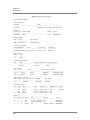
1. Press <Enter> to continue. # <Enter>
END USER SOFTWARE LICENSE IMPORTANT ‐ READ BEFORE INSTALLING OR OPERATING THIS PRODUCT
LICENSEE AGREES TO BE BOUND BY THE TERMS OF THIS AGREEMENT BY INSTALLING, HAVING INSTALLED, COPYING, OR OTHERWISE USING THE PRODUCT. IF LICENSEE DOES NOT AGREE, DO NOT INSTALL OR USE THE PRODUCT.
1. Scope. This License applies to the software product ("Software") you have licensed from F5 Networks, Inc. ("F5"). Certain Software is licensed for use in conjunction with F5 hardware which together with the Software will be referenced as the "Product". This License is a legal agreement between F5 and the single entity ("Licensee") that has acquired the Software from F5 under these terms and conditions. The Software incorporates certain third party software programs subject to the terms and restrictions of the applicable licenses identified herein.
...
2. Enter 'yes' to accept these terms and conditions
in the format 'yes' or 'no'. # yes
The switch's management port requires an IP address and mask.
3. Enter the management port IP address
in the format nnn.nnn.nnn.nnn or 'none'. # 10.1.27.69
4. Enter the management port subnet mask
in the format nnn.nnn.nnn.nnn.(default=255.0.0.0) # 255.255.255.0
The switch's management port requires a gateway IP address.
5. Enter the gateway IP address for the management interface
in the format nnn.nnn.nnn.nnn or 'none'.(default=10.1.1.1) # 10.1.27.1
A switch replacement requires additional configuration questions.
6. Are you doing a switch replacement?
in the format 'yes' or 'no'.(default=no) # no
The crypto‐officer is the most privileged user in the system.
7. Enter the crypto‐officer username
in the format text (1‐28 characters). # admin
8. Enter the crypto‐officer password
in the format text (6‐28 characters). # mypassword
Confirm the system password # mypassword
A system password is required for access to the master key.
9. Enter a system password
in the format text (12‐28 characters). # d0uble$ecRET
Confirm the system password # d0uble$ecRET
The master key is used to encrypt critical security parameters.
10. Enter the master key
in the format base64‐encoded key or keyword 'generate'.(default=generate) # <Enter>
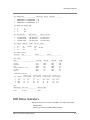
The system displays a configuration summary, for example:
Configuration Summary
Management IP Address 10.1.27.69
Management IP Mask 255.255.255.0
ARX®6000 Hardware Installation Guide
7-5
Chapter 7
Connecting the Switch to the Network
Management Gateway 10.1.27.1
Power Configuration 220
Private IP Subnet 169.254.6.0
Private IP Mask 255.255.255.0
Private VLAN 1008
Private Metalog VLAN 1009
Chassis GUID 3d17e8ce‐571e‐11dc‐9852‐ef323fbb290f
Switch Password #######
Switch Master Key generate
Crypto‐officer Username admin
Crypto‐officer Password #######
Enter 'yes' to load configuration or 'r' to restart #yes
You have completed the switch startup configuration.
The switch will now initialize the local database.
When the login prompt appears, log into the switch using
the crypto‐officer's username and password.
Closing configuration file.
Processing configuration file. (boot‐config)
...
The boot-up prompts continue until you reach the “Username” prompt.
Confirm that an administrator can log in by using the Crypto-Officer
username and password that you entered in the initial-boot script. For
example:
...
User Access Authentication
Username: admin
Password: mypassword
SWITCH>
The switch is now ready for configuration through the GUI or the CLI. See
the ARX® GUI Quick Start: Network Setup manual for instructions on using
the GUI to set up network parameters, or the ARX® CLI
Network-Management Guide for detailed network-configuration
instructions.
Preparing for Switch Replacement
For switch replacement, the process detailed previously becomes more
complicated.
You can replace a single switch or a switch that is a member of a redundant
pair. The interview that runs during installation is the same regardless of the
type of replacement. For a single switch replacement, there are a few things
you must have done prior to the switch failing. This includes saving your
running and global configs, UUID, and master key and associated
passwords as described in the ARX® Site Planning Guide, Best Practice:
Regularly Saving the Configuration, on page 1-62. The only other
7-6
Booting the Switch
differences between replacing a single switch and replacing a member of a
redundant pair is that for a single switch, a re-import is required at the
appropriate point during configuration. Since with a single switch
installation, the configuration is not saved on a backup switch, you have to
manage what you do with these key pieces of configuration data prior to the
switch’s failing.
Before You Begin: Verifying Hardware Compatibility
The replacement switch’s hardware must match that of the failed switch. At
the end of the switch replacement, you will run the failed switch’s
running-config on the replacement switch. The running-config includes slot
numbers for the modules, so the new switch must have its modules in the
same slots as its predecessor. Before you begin the replacement process,
verify that the replacement switch has all of its ASMs and NSMs in the
same positions as the failed switch.
Choosing Switch Replacement
The initial-boot script asks if this is a switch replacement. Answer yes to
invoke the questions that are required to replace the failed switch. For
example,
...
A switch replacement requires additional configuration questions.
6. Are you doing a switch replacement?
in the format 'yes' or 'no'.(default=no) # yes
Matching the Private Subnet
The next set of questions ask for the switch’s private subnet, the private
VLAN for that subnet, and the VLAN for a private metalog subnet. If the
failed switch was in a redundant pair and/or RON network, the private
subnets of the replacement switch should match those of the switch that
failed. Each ARX® uses its private subnet for communication with other
ARX®es in the same Resilient-Overlay Network (RON) and/or the switch’s
redundant peer. All private subnets in the RON and/or pair are carried by the
same VLAN. This private VLAN, and the separate metalog VLAN, must be
reserved for ARX® traffic only.
The private-subnet and VLAN information appears at the top of a the failed
switch’s show running-config output. For example, this is the top of a
running-config file from a failed switch. The private-subnet information is
highlighted in bold text:
; ARX‐6000
; Version 5.02.000.12535 (Feb 5 2010 18:16:05) [nbuilds]
; Database version: 502000.21
; Generated running‐config Sun Feb 14 01:44:06 2010
; System UUID 3d17e8ce‐571e‐11dc‐9852‐ef323fbb290f
; ip private vlan internal 1008 metalog 1009 subnet 169.254.17.0 255.255.255.0
;
terminal character‐set unicode‐utf‐8
;================================= vlan ==================================
config
ARX®6000 Hardware Installation Guide
7-7
Chapter 7
Connecting the Switch to the Network
vlan 81
...
Entering the Private Subnet
Enter the private subnet and VLAN of the failed switch, as well as the
VLAN for the private metalog subnet. The VLANs must be unique in your
network, shared only amongst the ARX®es in the RON. The defaults (1002
and 1003) may be sufficient for your installation. For example:
...
The switch's internal subnet requires an IP address and mask.
7. Enter the switch's private IP address
in the format nnn.nnn.nnn.nnn.(default=169.254.6.0) # 169.254.17.0
8. Enter the switch's private subnet mask
in the format nnn.nnn.nnn.nnn.(default=255.255.255.0) # <Enter>
The private subnet VLAN is used externally for redundancy traffic.
Be sure this value does not conflict with existing VLAN IDs.
9. Enter the chassis's private subnet VLAN
in the format integer [1‐4095].(default=1002) # 1008 <Enter>
The private subnet metalog VLAN is used for storing file‐change
logs on battery‐backed NVRAM, possibly on a redundant peer.
Be sure this value does not conflict with existing VLAN IDs.
10. Enter the chassis's private subnet metalog VLAN
in the format integer [1‐4095].(default=1003) # 1009 <Enter>
Finding the UUID of the Failed Switch
When a switch imports storage from back-end filers, it marks each share
with its Universally-Unique ID (UUID). A replacement switch must use the
same UUID or it rejects all of the shares used by its predecessor. You also
need to set the UUID if the switch is brought back to its factory defaults; a
“Manufacturing Installation” by F5 personnel resets the switch and its
UUID.
The UUID appears at the top of a switch’s show running-config output. For
example, this is the top of a running-config file from a switch named
“minturnA.” The UUID is highlighted in bold text:
; ARX‐6000
; Version 5.02.000.12535 (Feb 5 2010 18:16:05) [nbuilds]
; Database version: 502000.21
; Generated running‐config Sun Feb 14 01:44:06 2010
; System UUID 3d17e8ce‐571e‐11dc‐9852‐ef323fbb290f
; ip private vlan internal 1008 metalog 1009 subnet 169.254.17.0 255.255.255.0
;
terminal character‐set unicode‐utf‐8
;================================= vlan ==================================
config
vlan 81
...
If the failed switch was a member of a RON, you can alternatively use show
ron from any other RON member. This shows the UUID even if the chassis
is no longer online. For example, the following command (run on another
switch in the RON) shows the UUID for the same failed chassis,
“minturnA.” Again, the UUID is highlighted in bold text:
7-8
Booting the Switch
prtlndA(cfg)# show ron
Switch Name HA Peer Switch Uptime
Status UUID Management Addr
‐‐‐‐‐‐‐‐‐‐‐‐‐‐‐‐‐‐‐‐‐‐‐‐‐‐‐‐‐‐‐‐‐‐‐‐‐‐‐‐‐‐‐‐‐‐‐‐‐‐‐‐‐‐‐‐‐‐‐‐‐‐‐‐‐‐‐‐‐‐‐‐‐‐‐‐‐‐
bstnA (None) 0 days, 02:07:57
ONLINE d9bdece8‐9866‐11d8‐91e3‐f48e42637d58 10.1.1.7
gffstnA (None) 0 days, 01:59:42
ONLINE e5d870ae‐571e‐1352‐916b‐ef324fbc05a2 10.1.49.60
minturnA (None) 0 days, 02:00:16
OFFLINE 3d17e8ce‐571e‐11dc‐9852‐ef323fbb290f 10.1.27.69
provA (None) 0 days, 02:08:11
ONLINE db922942‐876f‐11d8‐9110‐8dtu78fc8329 10.1.38.19
prtlndA prtlndB 0 days, 02:07:59
ONLINE 876616f6‐79ac‐11d8‐946f‐958fcb4e6e35 10.1.23.11
prtlndB prtlndA 0 days, 00:18:55
ONLINE 64dcab94‐a2b6‐11d8‐9d25‐bf2c991c83f9 10.1.23.12
prtlndA(cfg)# ...
Applying the UUID
The next prompt in the initial-boot script asks for the UUID. Enter the
UUID of the failed switch. For example,
...
The UUID should only be entered if this chassis is replacing a failed chassis
and the entered UUID should match the UUID of the failed chassis.
11. Enter the chassis's UUID
in the format xxxxxxxx‐xxxx‐xxxx‐xxxx‐xxxxxxxxxxxx.(default=d4ukjce8‐1854‐11d8‐91e3‐f48e42637d58) # 3d17e8ce‐571e‐11dc‐9852‐ef323fbb290f
...
Important
No two running chassis should ever share the same UUID. Only enter the
UUID in a switch-replacement scenario.
Installing a Redundant Peer or Cluster
If you are installing the second switch in a redundant pair (called an ARX
cluster) or if you are configuring a second ARX cluster in a Disaster
Recovery (DR) configuration, you need to provide additional information to
the initial-boot script. All members of the cluster share a common master
key.
Note
A master key is an encryption key for all critical-security parameters
(CSPs), such as administrative passwords.
ARX®6000 Hardware Installation Guide
7-9
Chapter 7
Connecting the Switch to the Network
Redundant switches must use the same master key because they share the
same users, groups, and passwords. In the case of of a DR configuration, all
four ARXs must be configured with a common master key.
At the switch that is currently installed, use the show master-key command
to create an encrypted copy of the master key.
The CLI prompts you for two passwords:
• System Password is a password entered at initial-boot time (see Sample:
Booting a Non-Replacement Switch, on page 7-4). It is 12-32 characters
long. This validates that you have permission to access the master key.
• Wrapping Password is set with this command. The security software uses
this to encrypt (and later decrypt) the master-key string.
Enter 12-32 characters. At least one character in this password must be a
number (0-9) or a symbol (!, @, #, $, and so on).
Save this password: you will need it to decrypt the master key later, on
the new switch.
This command outputs a base64-encoded string that is the encrypted master
key. Save this string and the wrapping password that you set in the
command.
For example, this shows the master key on a switch named “minturnB:”
minturnB# show master‐key
Master Key System Password: %uper$ecretpw
Wrapping Password: an0ther$ecretpw
Validate Wrapping Password: an0ther$ecretpw
Encrypted master key:
2oftVCwAAAAgAAAApwazSRFd2ww/H1pi7R7JMDZ9SoIg4WGA/XsZP+HcXjsIAAAADDRbM
CxE/bc=
minturnB# ...
Applying the Master Key
As shown in an example earlier, there is a prompt for the master key in the
initial-boot script. You can answer this prompt with the encrypted master
key; the script then prompts for the wrapping password. For example,
...
The master key is used to encrypt critical security parameters.
15. Enter the master key
in the format base64‐encoded key or keyword 'generate'.(default=generate) # 2oftVCwAAAAgAAAApwazSRFd2ww/H1pi7R7JMDZ9SoIg4WGA/XsZP+HcXjsIAAAADDRbMCxE/bc=
The wrapping password in use to encrypt and decrypt the master key.
16. Enter the wrapping password
in the format text (6‐28 characters). # an0ther$ecretpw
Confirm the wrapping password # an0ther$ecretpw
...
7 - 10
Booting the Switch
Sample: Replacing a Redundant Peer
This sample script uses the private subnet, the UUID, and the master key to
replace a failed peer.
F5 ARX Switch Startup
This F5 ARX switch does not currently have critical system
information programmed. The following wizard prompts you
for this information. You can connect to the switch through
the out‐of‐band management interface when you finish.
To restart the configuration program, enter 'r' at any prompt.
Acknowledge acceptance of the following terms and conditions
by entering 'yes' at the next question.
1. Press <Enter> to continue. # <Enter>
LICENSE AGREEMENT
...
2. Enter 'yes' to accept these terms and conditions
in the format 'yes' or 'no'. # yes
The switch's management port requires an IP address and mask.
3. Enter the management port IP address
in the format nnn.nnn.nnn.nnn or 'none'. # 10.1.27.69
4. Enter the management port subnet mask
in the format nnn.nnn.nnn.nnn.(default=255.0.0.0) # 255.255.255.0
The switch's management port requires a gateway IP address.
5. Enter the gateway IP address for the management interface
in the format nnn.nnn.nnn.nnn or 'none'.(default=10.1.1.1) # 10.1.27.1
This next question invokes the questions for switch replacement:
A switch replacement requires additional configuration questions.
6. Are you doing a switch replacement?
in the format 'yes' or 'no'.(default=no) # yes
The switch's internal subnet requires an IP address and mask.
7. Enter the switch's private IP address
in the format nnn.nnn.nnn.nnn.(default=169.254.11.0) # 169.254.17.0
8. Enter the switch's private subnet mask
in the format nnn.nnn.nnn.nnn.(default=255.255.255.0) # <Enter>
The private subnet VLAN is used externally for redundancy traffic.
Be sure this value does not conflict with existing VLAN IDs.
9. Enter the chassis's private subnet VLAN
in the format integer [1‐4095].(default=1002) # 1008 <Enter>
The private subnet metalog VLAN is used for storing file‐change
logs on battery‐backed NVRAM, possibly on a redundant peer.
Be sure this value does not conflict with existing VLAN IDs.
10. Enter the chassis's private subnet metalog VLAN
ARX®6000 Hardware Installation Guide
7 - 11
Chapter 7
Connecting the Switch to the Network
in the format integer [1‐4095].(default=1003) # 1009 <Enter>
The UUID should only be entered if this chassis is replacing a failed chassis
and the entered UUID should match the UUID of the failed chassis.
11. Enter the chassis's UUID
in the format xxxxxxxx‐xxxx‐xxxx‐xxxx‐xxxxxxxxxxxx.(default=d4ukjce8‐1854‐11d8‐91e3‐f48e42637d58) # 3d17e8ce‐571e‐11dc‐9852‐ef323fbb290f
The crypto‐officer is the most privileged user in the system.
12. Enter the crypto‐officer username
in the format text (1‐28 characters).(default=admin) # admin
13. Enter the crypto‐officer password
in the format text (6‐28 characters). # mypassword
Confirm the system password # mypassword
A system password is required for access to the master key.
14. Enter a system password
in the format text (12‐28 characters). # d0uble$ecRET
Confirm the system password # d0uble$ecRET
This is the master-key question, where you use the encrypted master key and
the wrapping password from the redundant peer:
The master key is used to encrypt critical security parameters.
15. Enter the master key
in the format base64‐encoded key or keyword 'generate'.(default=generate) # 2oftVCwAAAAgAAAApwazSRFd2ww/H1pi7R7JMDZ9SoIg4WGA/XsZP+HcXjsIAAAADDRbMCxE/bc=
The wrapping password in use to encrypt and decrypt the master key.
16. Enter the wrapping password
in the format text (6‐28 characters). # an0ther$ecretpw
Confirm the wrapping password # an0ther$ecretpw
Configuration Summary
Management IP Address 10.1.27.69
Management IP Mask 255.255.255.0
Management Gateway 10.1.27.1
Power Configuration 220
Private IP Subnet 169.254.17.0
Private IP Mask 255.255.255.0
Private VLAN 1008
Private Metalog VLAN 1009
Chassis GUID 3d17e8ce‐571e‐11dc‐9852‐ef323fbb290f
Switch Password #######
Switch Master Key 2oftVCwAAAAgAAAApwazSRFd2ww/H1pi7R7JMDZ9SoIg4WGA/XsZP+HcXjsIAAAADDRbMCxE/bc=
Wrapping Password #######
Crypto‐officer Username admin
Crypto‐officer Password #######
Enter 'yes' to load configuration or 'r' to restart #yes
You have completed the switch startup configuration.
The switch will now initialize the local database.
When the login prompt appears, log into the switch using
the crypto‐officer's username and password.
7 - 12
Booting the Switch
Closing configuration file.
Processing configuration file. (boot‐config)
...
User Access Authentication
Username: admin
Password: mypassword
SWITCH>
The switch is now ready for configuration through the GUI or CLI.
To join it with its redundant peer, you can use the standard practice of
copying and applying the failed switch’s running config:
SWITCH> enable
SWITCH# copy ftp://juser:[email protected]/feb6config scripts running
SWITCH# show scripts
scripts
running Apr 12 17:45 2.1k
SWITCH# run scripts running
The running-config script sets up all local parameters, such as the hostname
and the network settings
SWITCH#; ARX‐6000
SWITCH#; Version 5.02.000.12535 (Feb 5 2010 18:16:05) [nbuilds]
SWITCH#; Database version: 502000.21
SWITCH#; Generated running‐config Sun Feb 14 01:44:06 2010
SWITCH#; System UUID 3d17e8ce‐571e‐11dc‐9852‐ef323fbb290f
SWITCH#; ip private vlan internal 1008 metalog 1009 subnet 169.254.17.0 255.255.255.0
SWITCH#; resource gateway 2
SWITCH#;
SWITCH#;================================= vlan ==================================
SWITCH#config
SWITCH# vlan 81
SWITCH# description "personnel dept."
SWITCH# members 4/1 to 4/1
SWITCH# members 4/2 to 4/2
SWITCH# exit
SWITCH#
SWITCH#...
SWITCH#;================================ system =================================
SWITCH#config
SWITCH(cfg)# clock timezone America New_York
SWITCH(cfg)# hostname minturnA
minturnA(cfg)# ip domain‐list wwmed.com
minturnA(cfg)# ...
minturnA(cfg)# exit
If you copied the private subnet and mask from the defunct switch, this
completes the switch replacement. Otherwise, the new switch learns its
private subnet from its peer, re-configures itself, and reboots. (A reboot is
necessary to change the private subnet of an ARX®.)
ARX®6000 Hardware Installation Guide
7 - 13
Chapter 7
Connecting the Switch to the Network
See the ARX® CLI Network-Management Guide for detailed configuration
instructions.
Connecting the Ethernet Management Port
After you boot the switch, you can connect the Ethernet out-of-band
management port on the SCM to a management station or network. You can
use this interface to access the Graphical User Interface (GUI) or the
Command Line Interface (CLI). To access the GUI, direct a web browser to
the interface over HTTPS (for example, “https://10.1.27.69/”). Use the
crypto-officer username and password, entered above, to log in. For the CLI,
use SSH with the interface and the crypto-officer username (for example,
“ssh [email protected]”).
The ARX® GUI Quick Start: Network Setup manual contains instructions for
getting started with the GUI, and the ARX® CLI Network-Management
Guide contains instructions and best practices for using the CLI to set up the
ARX®.
7 - 14
8
Maintenance
This chapter addresses the ARX®6000 manual power-down sequence as
well as describing the hardware power-on self-test (POST) diagnostics and
module status indicators (LEDs) and their associated conditions.
• Powering Down the ARX®6000
• POST Diagnostics
• LED Status Indicators
Powering Down the ARX®6000
Powering Down the ARX 6000
®
The ARX®6000 requires a manual power-down sequence, which cuts power
from all systems including the NVRAM. Once the NVRAM loses power
from an external source, it uses a battery backup for up to 72 hours.
For details on powering down a single ARX® and a redundant pair, consult
the ARX® CLI Maintenance Guide, Powering Down the ARX, on page 13-1.
This prepares the ARX® pair for a planned power outage.
For power outages of greater than 72 hours, contact F5 Support.
POST Diagnostics
When the switch reboots and the modules power-up, POST (power-on
self-test) diagnostics run on each module to verify their basic hardware
integrity. You can view any hardware failures at the system console through
the show version and show chassis commands. See the following sample
output.
Figure 8.1 Show Version Sample
minturnA> show version
Copyright (c) 2002‐2010 by F5 Networks, Inc. All rights reserved.
Running Release
test1.rel : Version 5.02.000.12535 (Feb 5 2010 18:16:05) [nbuilds]
Armed Release
test1.rel : Version 5.02.000.12535 (Feb 5 2010 18:16:05) [nbuilds]
Backup Release
test2.rel : Version 5.02.000.12535 (Feb 5 2010 18:16:05) [nbuilds]
System Configuration: Version 502000.21
minturnA uptime is 0 weeks, 0 days, 1 hours, 25 minutes.
Slot Admin ModuleType ModuleState FW Upgrade
‐‐‐‐ ‐‐‐‐‐‐‐ ‐‐‐‐‐‐‐‐‐‐‐‐ ‐‐‐‐‐‐‐‐‐‐‐‐‐‐‐‐ ‐‐‐‐‐‐‐‐‐‐
1 Enabled SCM Online Disabled
2 Enabled ASM Online Disabled
3 Enabled ‐‐‐ Empty Disabled
4 Enabled NSM Online Disabled
5 Enabled ‐‐‐ Empty Disabled
6 Enabled ‐‐‐ Empty Disabled
Resource State Forwarding
‐‐‐‐‐‐‐‐ ‐‐‐‐‐‐‐‐‐‐‐‐‐‐‐‐‐‐‐‐‐‐‐‐‐‐‐‐‐‐‐ ‐‐‐‐‐‐‐‐‐‐
Switch Up Disabled
ARX®6000 Hardware Installation Guide
8-3
Chapter 8
Maintenance
Figure 8.2 Show Chassis Sample
minturnA> show chassis
Identification:
Hostname UUID
‐‐‐‐‐‐‐‐‐‐‐‐‐‐‐‐‐‐‐‐‐‐‐‐‐‐‐‐‐‐‐‐‐‐‐‐ ‐‐‐‐‐‐‐‐‐‐‐‐‐‐‐‐‐‐‐‐‐‐‐‐‐‐‐‐‐‐‐‐‐‐‐‐‐‐
minturnA 3d17e8ce‐571e‐11dc‐9852‐ef323fbb290f
Chassis:
Chassis Type Model Number HW Ver. Serial
‐‐‐‐‐‐‐‐‐‐‐‐ ‐‐‐‐‐‐‐‐‐‐‐‐‐‐‐‐‐‐‐‐‐‐‐‐‐‐‐‐‐‐‐‐‐‐‐‐ ‐‐‐‐‐‐‐ ‐‐‐‐‐‐‐‐‐‐‐‐‐
ARX‐6000 ARX6 A 01 0216030011
Private Subnet:
VLAN Subnet Subnet Mask
‐‐‐‐ ‐‐‐‐‐‐‐‐‐‐‐‐‐‐‐‐ ‐‐‐‐‐‐‐‐‐‐‐‐‐‐‐‐
1008 169.254.17.0 255.255.255.0
Chassis Environment:
Base MAC Address Power Fan(setting) Temperature
‐‐‐‐‐‐‐‐‐‐‐‐‐‐‐‐‐ ‐‐‐‐‐‐‐‐‐‐‐‐‐‐ ‐‐‐‐‐‐‐‐‐‐‐‐‐ ‐‐‐‐‐‐‐‐‐‐‐‐‐
00:0a:49:00:0b:00 Online Partial Online (low) Normal 27 C
Power Details:
Power State
‐‐‐‐‐‐ ‐‐‐‐‐
A Absent
Logical Disk Details:
Disk Status Verification Mode Verification Rate
‐‐‐‐‐‐ ‐‐‐‐‐‐‐‐‐‐‐‐‐‐‐‐‐‐‐‐‐ ‐‐‐‐‐‐‐‐‐‐‐‐‐‐‐‐‐ ‐‐‐‐‐‐‐‐‐‐‐‐‐‐‐‐‐
1 Optimal Automatic 10 %
Disk Details:
Disk Size State Transfer Rate Model
‐‐‐‐‐‐‐‐ ‐‐‐‐‐‐‐‐‐‐‐ ‐‐‐‐‐‐‐‐‐‐‐‐‐‐‐‐‐ ‐‐‐‐‐‐‐‐‐‐‐‐‐ ‐‐‐‐‐‐‐‐‐‐‐‐‐‐‐‐‐
Bay 1 68.50G Online 320MB/sec ATLAS10K4_73SCA
Bay 2 68.50G Online 320MB/sec ATLAS10K4_73SCA
RAID Controller Details:
Rebuild Rate Max Transfer Rate Firmware RAID Alarm
‐‐‐‐‐‐‐‐‐‐‐‐ ‐‐‐‐‐‐‐‐‐‐‐‐‐‐‐‐‐ ‐‐‐‐‐‐‐‐‐‐‐‐‐ ‐‐‐‐‐‐‐‐‐‐‐‐
90 % 320MB/sec 1L49:G500 Enabled
Slot Environment:
Slot Type State Power Temperature NVR Battery Drive
‐‐‐‐ ‐‐‐‐‐ ‐‐‐‐‐‐‐‐‐‐‐‐‐‐‐‐ ‐‐‐‐‐‐‐ ‐‐‐‐‐‐‐‐‐‐‐‐‐‐ ‐‐‐‐‐‐‐‐‐‐‐ ‐‐‐‐‐‐‐‐‐
1 SCM Online Online Normal (<45 C) Good LSI Good
2 ASM Online Online Normal (<65 C) N/A
4 NSM Online Online Normal (<65 C) N/A
Module:
Slot Ports Procs Card Xeon Sibyte Serial
‐‐‐‐ ‐‐‐‐‐ ‐‐‐‐‐ ‐‐‐‐‐‐‐‐ ‐‐‐‐‐‐‐‐‐‐‐‐‐‐‐‐‐ ‐‐‐‐‐‐‐‐‐‐‐‐‐‐‐‐‐ ‐‐‐‐‐‐‐‐‐‐‐‐
1 1 1 SCM 2.0 GHz 4096 MB N/A 0307070293
2 0 2 ASM 2.4 GHz 4096 MB N/A 0307070223
4 6 6 NSM_TX N/A 700 MHz 2048 MB 0304070061
8-4
LED Status Indicators
Slot MAC Address HW Version Rework Deviation
‐‐‐‐ ‐‐‐‐‐‐‐‐‐‐‐‐‐‐‐‐‐‐‐‐‐‐‐‐‐‐‐‐ ‐‐‐‐‐‐‐‐‐‐ ‐‐‐‐‐‐ ‐‐‐‐‐‐‐‐‐‐‐‐‐‐‐‐‐‐‐‐
1 000A49000B09 to 000A49000B09 D 20
2 000A49000B15 to 000A49000B16 C 16
4 000A49000B27 to 000A49000B32 B 22
Slot Reset CPLD Keeper CPLD
‐‐‐‐ ‐‐‐‐‐‐‐‐‐‐ ‐‐‐‐‐‐‐‐‐‐‐
1 1 3
2 0 N/A
4 13 N/A
Slot Boot Version Diag Version BootLdr Version
‐‐‐‐ ‐‐‐‐‐‐‐‐‐‐‐‐‐‐‐‐ ‐‐‐‐‐‐‐‐‐‐‐‐‐‐‐‐ ‐‐‐‐‐‐‐‐‐‐‐‐‐‐‐‐
1 2.03.000.09144 3.01.000.10731 3.01.000.10731
2 2.03.000.09144 3.01.000.10731 3.01.000.10731
4 5.01.000.11898 5.01.000.11898 5.01.000.11898
Slot SSB ver NVR ver Speed MTL Ver Speed
‐‐‐‐ ‐‐‐‐‐‐‐ ‐‐‐‐‐‐‐‐‐‐‐‐‐‐‐‐ ‐‐‐‐‐‐‐‐‐‐‐‐‐‐‐‐‐‐‐
1 67 24 10 Gbps N/A
2 67 N/A 20 10 Gbps
4 67 N/A N/A
Port Media Details:
Slot/Port Type Vendor Status
‐‐‐‐‐‐‐‐‐ ‐‐‐‐‐‐‐‐‐‐‐‐‐‐‐ ‐‐‐‐‐‐‐‐‐‐‐‐‐‐‐ ‐‐‐‐‐‐‐‐‐‐‐‐‐‐‐‐‐‐‐‐‐‐‐
Disk Usage:
Name Total MB Used MB Free MB Used%
‐‐‐‐‐‐‐‐‐‐‐‐‐‐‐‐‐‐‐‐‐‐‐‐‐‐‐‐‐‐‐‐ ‐‐‐‐‐‐‐‐‐‐ ‐‐‐‐‐‐‐‐‐‐ ‐‐‐‐‐‐‐‐‐‐ ‐‐‐‐‐
System 3173 1401 1610 47%
Releases 5285 2681 2335 54%
Logs 30037 56 28455 1%
Cores; DiagInfo; Lists 8458 162 7866 3%
Scripts 3172 178 2833 6%
Reports 8458 33 7994 1%
Temperature Details:
Sensor 1 (C) Sensor 2 (C) Sensor 3 (C) Sensor 4 (C)
Slot Module Local Remote Local Remote Local Remote Local Remote
‐‐‐‐ ‐‐‐‐‐‐ ‐‐‐‐‐ ‐‐‐‐‐‐ ‐‐‐‐‐ ‐‐‐‐‐‐ ‐‐‐‐‐ ‐‐‐‐‐‐ ‐‐‐‐‐ ‐‐‐‐‐‐
1 SCM 25 26 27 32 N/A N/A N/A N/A
2 ASM 32 27 28 27 21 22 24 22
4 NSM 28 57 30 49 24 49 N/A N/A
NVR:
NVR Battery ECC State NVR Size (MB)
‐‐‐‐‐‐‐‐‐‐‐ ‐‐‐‐‐‐‐‐‐‐‐‐‐‐‐‐‐‐‐‐‐‐ ‐‐‐‐‐‐‐‐‐‐‐‐‐
Good No Error 1024
LED Status Indicators
This section describes the system status LEDs and conditions, including:
• Module LEDs
• Ethernet-port link-status LEDs (NSM and SCM)
ARX®6000 Hardware Installation Guide
8-5
Chapter 8
Maintenance
• Disk-drive LEDs
• Fan tray LEDs
Module Status LEDs
Each module front panel provides the following LED status indicators:
ALERT — Illuminates Red to indicate an operational failure
STATUS — Illuminates Green or Yellow based on the current operational
state
During various module operations, module LEDs display Green, Yellow, or
Red with intermittent blinking patterns, depending on the state. When
blinking, LEDs are on for a half second and off for a half second.
Table 8.1 describes the LED colors and blinking patterns that describe the
module’s operational status. You can find more details on the Module
State(s) from the output of the show version, show processors, or show
chassis CLI commands.
ALERT
STATUS
Module State(s)
(Off)
Green
Online
Red
Green (Blinking)
Powering up and running all POST tests.
This pattern persists until/unless all POST tests pass. If it persists indefinitely,
POST tests must have failed. In the latter case, you may need to replace the
module; module-replacement procedures appear in an appendix of this manual.
(Off)
Green (Blinking)
Boot: POST tests passed. The module is running internal diagnostics and then
booting.
Downloading: the module’s processor’s are downloading new software and/or
firmware. This state only occurs for processors that need it, and it occurs after the
“Init” state (below).
(Off)
Yellow (Blinking)
(Off)
Yellow
Init: the module is provisioning its processor(s).
Online Partial: at least one processor is online, at least one is not online yet.
If the offline processor does not come up in 5 minutes, this changes to Failed
Partial.
Red
Yellow
Failed Partial: at least one processor is online, but at least one other processor
failed. You may need to replace the module, as described in an appendix of this
manual.
Red
(Off)
Failed. You may need to replace the module, as described in an appendix of this
manual.
Table 8.1 Module Operational States and LED Patterns
8-6
LED Status Indicators
Ethernet-Port Link Status LEDs
MGMT Port on the SCM
The out-of-band management port on the System Control Module (SCM),
labeled “MGMT,” has two LEDs:
• Top – Link-status LED: steady green indicates that the port is enabled
and a link is established.
• Bottom – Activity LED: blinking green indicates packet traffic.
Link LED for Each NSM Port
Each client/server port on the Network Services Module (NSM) has
link-status LED labeled “Link.” This has the same function as the
Link-status LED on the MGMT port: steady green indicates that the port is
enabled and a link is established. There is no Activity LED for the
client/server ports.
The Link LED is over each Ethernet port in the NSM-TX, but it is under
each Fibre port in the NSM-FX.
Disk Drive LEDs
The system disk drives provide three status LEDs:
• Red — indicates Activity
• Green — indicates Power
• Orange — indicates Failure
Fan Tray LEDs
The fan-tray module front panel provides two status LEDs, ALERT (top)
and STATUS (bottom). Table 8.2 describes the fan tray LED indicators and
associated conditions.
ALERT
STATUS
Condition
(Off)
Green
No failures.
(Off)
Yellow
Warning. This could indicate one of the following conditions:
•
Single-fan failure,
•
Temperature >50 degrees C, or
•
Temperature sensor open.
Contact F5 Support; you may need to replace the entire fan tray, as described in an
appendix of this manual.
Table 8.2 Fan Tray Status LEDs
ARX®6000 Hardware Installation Guide
8-7
Chapter 8
Maintenance
ALERT
STATUS
Condition
Red
Yellow
Multiple-fan failure. Replace the fan tray as described in the appendix.
Red
Green
SCM-to-fan tray communication failure. This indicates a failure of the fan controller in the
fan tray. Replace the fan tray as described in the appendix.
Table 8.2 Fan Tray Status LEDs (Continued)
8-8
A
Cable Connectors
• ARX®6000 Connectors
• Console Connector and Pinouts
• SFP Optical Connector
ARX®6000 Connectors
ARX 6000 Connectors
®
This appendix describes the cable connectors used on the ARX®6000
modules (see Table A.1).
Module
Connector
System Control Module (SCM)
RJ-45
Purpose
•
Ethernet management port
•
Mirror port for port mirroring and
diagnostics
•
Serial console port
Network Services Module (NSM)
Copper version
RJ-45
Six 100/1000BASE-T Ethernet portsa
Optical version
small form-factor
pluggable (SFP)
Six optical ports for 1-Gbps Ethernet
connections over multi-mode fiber
Important
Fiber-optic ports (on modules) are shipped with cable connectors
installed. These ports must be protected by a rubber grommet filler or a
cable connector at all times to prevent dust from collecting in the
transceiver.
Table A.1 Module Cable Connectors
a.NSM Gigabit Ethernet ports support automatic MDI/MDIX cross-over. This feature automatically corrects the polarity of
the attached CAT5 cable, regardless if it is a cross-over or straight-through type. However, for this feature to work, the port
must be set to “auto-negotiate” (enabled). When the port speed/duplex is forced (auto-negotiate is disabled), automatic
MDI/MDIX cross-over is disabled, and you must cable the port using standard cross-over or straight-through cabling.
ARX®6000 Hardware Installation Guide
A-3
Appendix A
Cable Connectors
Console Connector and Pinouts
The serial Console port requires a rollover cable (RJ-45 to RJ-45) that is
included with the ARX®-installation kit. This cable is sufficient for
connecting to a Terminal Server. For a direct connection to the serial port on
a management station (such as a laptop), an RJ-45 to DB9 adapter is also
included in the kit.
Figure A.1 RJ-45 Male Connector
Figure A.2 RJ-45 to Serial DB9 Adapter
Table A.2 lists the RJ-45 pinout assignments for the rollover cable and the
adapter. The left column shows the transmit (TxD), ground (GND), and
receive (RxD) signals. and the right column shows the signals reversed at
the console device. The intervening columns show the pins that carry each
of those signals.
SCM/ACM
Console Port
RJ-45 Rollover Cable
RJ-45 to DB9 Adapter
Console
Device
DTE Signal
RJ-45
Pinout
USOC
Color
RJ-45
Pinout
RJ-45
Pinout
T568 Color
DB9F
Pinout
DTE Signal
TxD
3
yellow
6
6
yellow
2
RxD
Table A.2 SCM Console Port Signaling/Cabling Using a Rollover Cable
A-4
SFP Optical Connector
SCM/ACM
Console Port
RJ-45 Rollover Cable
RJ-45 to DB9 Adapter
GND
4
green
5
5
green
GND
5
red
4
4
red
RxD
6
black
3
3
black
Console
Device
5
Signal
Ground
3
TxD
Table A.2 SCM Console Port Signaling/Cabling Using a Rollover Cable (Continued)
SFP Optical Connector
The Network Services Module (NSM) optical version uses small
form-factor pluggable (SFP) optical connectors for connection to Ethernet
over fiber-optic cable.
Figure A.3 shows an example SFP connector.
Figure A.3 SFP Optical Connector
WARNING
Fiber-optic ports are shipped with cable connectors installed. These ports
must be protected by a rubber grommet filler or a cable connector at all
times to prevent dust from collecting in the transceiver.
ARX®6000 Hardware Installation Guide
A-5
Appendix A
Cable Connectors
A-6
B
Removing and Replacing FRUs
This chapter describes how to remove and replace the following
field-replaceable units (FRUs) in the ARX®6000 chassis:
• Before You Begin
• Removing and Replacing Modules
• Removing and Replacing a Disk Drive
• Removing and Replacing the Fan Tray
• Removing and Replacing a Power Supply
• Removing and Replacing the Air Filter
Note
Other than the power supplies, these FRUs are hot-swappable components.
You do not need to power off the switch before replacing them. However,
module replacement often causes a reboot (and a failover, if the ARX® is the
active peer in a redundant pair).
Before You Begin
Before You Begin
WARNING
Static electricity can damage switch components. Be sure to wear antistatic
wrist straps before handling hardware modules and disk drives. The plug is
located on the left side of the cable guide on the bottom front of the chassis
(shown in Figure 6.8 on page 6-14).
Removing and Replacing Modules
Important
Removing a non-NSM module (or the only NSM) causes the switch to
reboot.
In a redundant pair where this switch is active, services fail over to the
junior switch. In a redundant pair where this switch is in the Backup/junior
role, service is unaffected. A standalone switch does not offer any service
for the duration of the reboot.
The module front panels provide ejector tabs that seat/unseat the modules in
their slots in the chassis. Ejector tab positions indicate:
• Ejector tab down or closed (flush against the module): module is
operational (online) (see Figure B.1)
• Ejector tab up or open (away from the module): module is not
operational (offline)
To remove and replace a module:
1. Loosen the captive screws (top and bottom) on the module to be
removed.
2. Release the ejector tabs (top and bottom) on the module.
3. Carefully slide the module out of its slot.
4. Insert the new module (of the same type) into the same slot by
pushing on the front panel while simultaneously engaging the
ejectors.
When the module connects (pins engage) at the backplane, the
module is online.
ARX®6000 Hardware Installation Guide
B-3
Appendix B
Removing and Replacing FRUs
5. Tighten the captive screws (top and bottom) on the new module.
WARNING
For modules with fiber-optic ports:
Fiber-optic ports must be protected by a rubber grommet filler or a cable
connector at all times to prevent dust from collecting in the transceiver.
Figure B.1 Ejector Tabs on Modules
down and locked
Removing and Replacing a Disk Drive
WARNING
Static electricity can damage switch components. Be sure to wear antistatic
wrist straps before handling disk drives and modules.
To remove a disk drive:
1. Insert a key and turn the lock to the right to release the drive handle.
(The drive is locked when the notch is pointing up. When you turn
the notch to the right, the handle will release (see Figure B.2).)
B-4
Removing and Replacing a Disk Drive
2. Pull the handle (hinged) toward you and slowly slide the disk drive
out of the bay.
Important
The drives must be locked to achieve proper seating in the drive bay.
Figure B.2 Removing a Disk Drive
Unlock key, then
pull handle
(hinged) out
toward you
Keys:
Notch up - drive
locked
Notch to the right
- drive unlocked
The chassis continues to run, in degraded state, with only one disk missing
from the RAID.
Silencing the RAID Alarm
After you remove the drive, an audible alarm goes off to signal that the drive
is missing. From the CLI (priv-exec mode), you can use the raid silence
command to quiet this alarm:
raid silence
For example, the following command sequence logs into a switch at
10.1.27.69, enters enable to go to priv-exec mode, and silences the RAID
alarm:
$ telnet 10.1.27.69
Trying 10.1.27.69...
Connected to 10.1.27.69.
Escape character is '^]'.
ARX®6000 Hardware Installation Guide
B-5
Appendix B
Removing and Replacing FRUs
Username: admin
Password: acopia
minturnA> enable
minturnA# raid silence
minturnA# ...
Replacing the Disk Drive
To replace the disk drive, slide it into the empty slot. Then use a key to lock
the drive in place. Rotate the key counterclockwise until notch is pointing
up.
Incorporating the Disk into the RAID
To incorporate the disk into the RAID, use the raid rebuild command from
priv-exec mode:
raid rebuild {disk1 | disk2}
where disk1 | disk2 specifies the disk to rebuild. The top disk is disk1.
For example, the following command rebuilds the upper disk:
minturnA# raid rebuild disk1
minturnA# ...
Removing and Replacing the Fan Tray
Remove the fan tray as described in Removing the Fan Tray, on page 6-7.
To replace the fan tray, reverse the steps. (The entire fan tray is the FRU, not
the individual fans.)
WARNING
After 60 seconds, a busy ARX® may overheat without its fan tray. An ARX®
with a light traffic load can last much longer. In any case, have the
replacement fan tray ready before you remove a running fan tray from the
chassis.
B-6
Removing and Replacing a Power Supply
Removing and Replacing a Power Supply
Remove a power supply as described in Removing the Power Supplies, on
page 6-7. To replace a power supply, reverse the steps.
DANGER
A chassis configured with two power supplies has two power cords. In the
event that AC power must be removed from the system, disconnect both
power cords before servicing the unit. Otherwise, the power-supply units
keep a charge for 10-15 minutes, and you could get an electric shock by
touching the pins on the back.
Removing and Replacing the Air Filter
WARNING
Customers are required to maintain the switch’s air filter at regular
intervals. Failure to do so may damage the switch.
To remove and replace the air filter:
1. Remove the air-filter front panel/cable guide by loosening the two
captive screws on either side of the panel (see Air Filter and Cable
Management, on page 6-13.) Be careful to keep cabling intact.
2. Slide the air filter out of the chassis and replace with a new air filter.
3. Reinstall the air-filter panel/cable guide over the air filter opening
by aligning the holes and tightening the captive screws.
ARX®6000 Hardware Installation Guide
B-7
Appendix B
Removing and Replacing FRUs
B-8
Index
Index
A
Bezel 6-9
Booting the switch 7-4
LEDs 8-7
removing 6-7
replacing B-6
File service protocols supported 2-5
Front bezel 6-9
FRUs
air filter B-7
and static electricity B-3, B-4
disk drive B-4
fan tray B-6
modules B-3
power supply B-7
C
H
Cable connectors A-3
Cable guides 6-13
Cable management 5-5
Cable requirements 5-5
Cabling the modules 6-13
Chassis configuration
slot allocations 3-3, 3-6
Chassis installation
safety instructions 6-3
tools required 6-3
Compliance
regulatory 5-6
Configuring the switch 7-4
Connecting serial console port 7-3
Connecting the management port 7-14
Console port
ARX6000 7-3
baud rate 7-3
connecting 7-3
connector A-3
Hard disks
in an ARX6000 3-4
Hardware 3-3
Adaptive Services Module
features 4-5
front panel LEDs 4-5
Air filter 6-13
replacing B-7
Audience for this manual 1-3
B
D
Diagnostics at switch bootup 8-3
Disk drives
(fig.) 3-4
configuration 3-4
dual-channel bus 3-4
LEDs 3-5, 8-7
locking down with key B-5
LUNs 3-5
removing and replacing B-4
Dual-channel SCMs 3-4
E
L
LEDs
disk drives 8-7
fan tray 8-7
module status and alert 8-6
port/link LEDs 8-7
Logical unit numbers (LUNs) 3-4
M
Management port
connecting 7-14
Management ports 7-3
MGMT interface
location on the ARX6000’s SCM 7-3
Module connectors A-3
Module LEDs 8-6
Modules
ASM 4-5
fan tray 3-5
NSM 4-5
POST diagnostics 8-3
power consumption 5-4
replacing B-3
SCM 4-3
N
Network protocols 2-5
Network Services Module
features 4-5
Ejector tabs on modules B-3
O
F
Operational status LEDs 8-6
Fan tray
features 3-5
ARX®6000 Hardware Installation Guide
Index - 3
Index
P
Ports
LEDs 8-7
management, console 7-3
NSM (fig.) 4-7
POST diagnostics 8-3
Power consumption 5-4
Power cords
attaching 6-11
Power ON/OFF switch 6-11
Power requirements 5-4
Power specifications 5-3
Power supply
(fig) 3-4
features 3-3
load-sharing 3-3
removing 6-7
replacing B-7
Protocols supported 2-5
R
Rack-mounting the switch 6-9
Redundancy
between two ARX6000’s 2-4, 3-7
Regulatory compliance 5-6
Removing and replacing a disk drive B-4
Removing and replacing modules B-3
Removing fan tray 6-7
Removing the power supply 6-7
Resilient Overlay Network (RON) 3-7
Running the boot wizard 7-4
S
Safety instructions 6-3
Serial console port 7-3
Site installation requirements 6-3
Slot assignments 3-6
Specifications 5-3
air filter 5-3
airflow clearance 5-3
chassis 5-3
modules 5-4
power 5-3
system 5-4
Static electricity B-3, B-4
Status LEDs 8-6
Switch boot-up 7-4
for a redundant switch 7-9
for a replacement switch 7-6
Switch Installation
safety instructions 6-3
tools required 6-3
unpacking and installing the chassis 6-1
Switch installation
Index - 4
See Also Switch boot-up.
Switch management ports 7-3
Switch replacement
See Switch Installation and Switch boot-up:for a
replacement switch.
Switch-to-switch failover 2-4
System Control Module
features 4-3
System power 5-3
System specifications 5-3
T
Tools for installation 6-3
U
Unpacking the switch 6-5