1
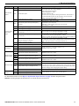
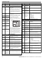
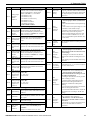
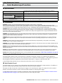
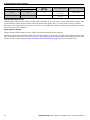
6 Parameter Table
No.
L3-06
T1-01
T1-02
T1-03
T1-04
T1-05
T1-06
T1-07
T1-08
T1-9
T1-10
T1-11
Monitor
U1-01
U1-02
U1-03
U1-05
U1-06
24
Name
Description
Stall
Prevention
Enabled when L3-05 is set to 1 or 2. 100%
Level during
is equal to the drive rated current.
Run
Induction Motor Auto-Tuning
0: Rotational Auto-Tuning
1: Stationary Auto-Tuning 1
2: Stationary Auto-Tuning for Line-to-Line
Resistance
3: Rotational Auto-Tuning for V/f Control
Auto-Tuning
(necessary for Energy Savings and Speed
Mode
Estimation Speed Search)
Selection
4: Stationary Auto-Tuning 2
8: Inertia Tuning (perform Rotational AutoTuning prior to Inertia Tuning)
9: ASR Gain Tuning (perform Rotational
Auto-Tuning prior to ASR Gain AutoTuning)
Sets the motor rated power as specified on
the motor nameplate.
Motor Rated
Note: Use the following formula to convert
Power
horsepower into kilowatts: kW = HP ×
0.746.
Motor Rated
Sets the motor rated voltage as specified on
Voltage
the motor nameplate.
Motor Rated
Sets the motor rated current as specified on
Current
the motor nameplate.
Motor Base
Sets the rated frequency of the motor as
Frequency
specified on the motor nameplate.
Number of
Sets the number of motor poles as specified
Motor Poles
on the motor nameplate.
Motor Base
Sets the rated speed of the motor as
Speed
specified on the motor nameplate.
PG Number of Set the number of pulses per revolution for
Pulses Per
the PG being used (pulse generator or
Revolution
encoder).
Sets the no-load current for the motor.
After setting the motor capacity to T1-02
Motor Noand the motor rated current to T1-04, this
Load Current
parameter will automatically display the no(Stationary
load current for a standard 4 pole Yaskawa
Auto-Tuning)
motor. Enter the no-load current as
indicated on the motor test report.
Sets the motor rated slip.
Motor Rated
After setting the motor capacity to T1-02,
Slip
this parameter will automatically display the
(Stationary
motor slip for a standard 4 pole Yaskawa
Auto-Tuning) motor. Enter the motor slip as indicated on
the motor test report.
Sets the iron loss for determining the
Energy Saving coefficient.
Motor Iron
The value is set to E2-10 (motor iron loss)
Loss
set when the power is cycled. If T1-02 is
changed, a default value appropriate for the
motor capacity that was entered will appear.
Description
Frequency Reference (Hz)
Output Frequency (Hz)
Output Current (A)
Motor Speed (Hz)
Output Voltage Reference (Vac)
Monitor
U1-07
U1-08
U1-09
Description
DC Bus Voltage (Vdc)
Output Power (kW)
Torque Reference (% of motor rated torque)
Displays the input terminal status.
U1 - 10= 0 0 0 0 0 0 0 0
input 1
1 Digital
(terminal S1 enabled)
input 2
1 Digital
(terminal S2 enabled)
input 3
1 Digital
(terminal S3 enabled)
U1-10
input 4
1 Digital
(terminal S4 enabled)
input 5
1 Digital
(terminal S5 enabled)
input 6
1 Digital
(terminal S6 enabled)
1 Digital input 7
(terminal S7 enabled)
1 Digital input 8
(terminal S8 enabled)
Displays the output terminal status.
U1 - 11= 0 0 0 0 0 0 0 0
1 Multi-Function
Digital Output
(terminal M1-M2)
U1-11
1 Multi-Function
Digital Output
(terminal M3-M4)
1 Multi-Function
Digital Output
(terminal M5-M6)
Not Used
Fault Relay
(terminal MA-MC closed
MA-MC open)
1
Verifies the drive operation status.
U1 - 12= 0 0 0 0 0 0 0 0
U1-12
1 During run
1 During zero-speed
1 During REV
fault reset
1 During
signal input
1 During speed agree
1 Drive ready
alarm
1 During
detection
1 During fault detection
U1-13
U1-14
U1-15
U1-16
U1-18
U1-24
U2-01
U2-02
U2-03
U2-04
U2-05
U2-06
U2-07
U2-08
U2-09
Terminal A1 Input Level
Terminal A2 Input Level
Terminal A3 Input Level
Output Frequency after Soft Starter
oPE Fault Parameter
Input Pulse Monitor
Fault Trace
Current Fault
Previous Fault
Frequency Reference at Previous Fault
Output Frequency at Previous Fault
Output Current at Previous Fault
Motor Speed at Previous Fault
Output Voltage at Previous Fault
DC Bus Voltage at Previous Fault
Output Power at Previous Fault
YASKAWA ELECTRIC TOEP C710616 27A YASKAWA AC Drive - A1000 Quick Start Guide