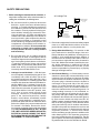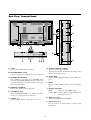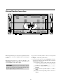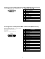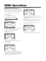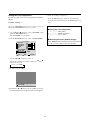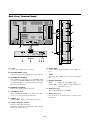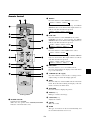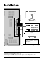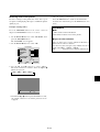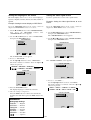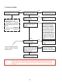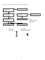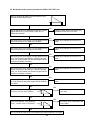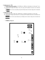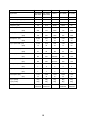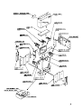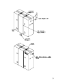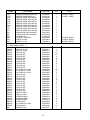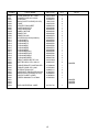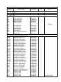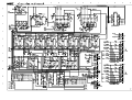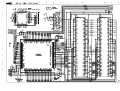
1
Service
Manual
PD6120D /U1B
Plasma Monitor
POWER/STANDBY
INPUT SELECT
VOLUME
REMARK : The PD6120D is a same product as the PX-61XM1A except the brand
indications and accessories.
Please refer to the PX-61XM1A service manual (PART No. 007A) except following
parts.
POS.
NO.
VERS.
PART NO.
DESCRIPTION
Following spare parts are different from PX-61XM1A ones. (refer page 9-1 )
ZK334W0010
RC5010DPD (03S120012)
PK30
02AW851210
USER GUIDE for PD6120D (07S900024)
M21
02AW248010
FRONT PANEL ASSY (029DS0221)
PD6120D
PK21
Please use this service manual with referring to the user guide (D.F.U) without fail.
R
PD6120D
Printed in Japan
02AW855010 SIG
F i r s t I s s u e : 2001.08
MARANTZ DESIGN AND SERVICE
Using superior design and selected high grade components, MARANTZ company has created the ultimate in stereo sound.
Only original MARANTZ parts can insure that your MARANTZ product will continue to perform to the specifications for which
it is famous.
Parts for your MARANTZ equipment are generally available to our National Marantz Subsidiary or Agent.
ORDERING PARTS :
Parts can be ordered either by mail or by Fax.. In both cases, the correct part number has to be specified.
The following information must be supplied to eliminate delays in processing your order :
1. Complete address
2. Complete part numbers and quantities required
3. Description of parts
4. Model number for which part is required
5. Way of shipment
6. Signature : any order form or Fax. must be signed, otherwise such part order will be considered as null and void.
USA
EUROPE / TRADING
AMERICAS
SUPERSCOPE TECHNOLOGIES, INC.
MARANTZ PROFESSIONAL PRODUCTS
2640 WHITE OAK CIRCLE, SUITE A
AURORA, ILLINOIS 60504 USA
PHONE : 630 - 820 - 4800
FAX
: 630 - 820 - 8103
AUSTRALIA
QualiFi Pty Ltd,
24 LIONEL ROAD,
MT. WAVERLEY VIC 3149
AUSTRALIA
PHONE : +61 - (0)3 - 9543 - 1522
FAX
: +61 - (0)3 - 9543 - 3677
NEW ZEALAND
WILDASH AUDIO SYSTEMS NZ
14 MALVERN ROAD MT ALBERT
AUCKLAND NEW ZEALAND
PHONE : +64 - 9 - 8451958
FAX
: +64 - 9 - 8463554
BRAZIL
MARANTZ EUROPE B.V.
P.O.BOX 80002, BUILDING SFF2
5600 JB EINDHOVEN
THE NETHERLANDS
PHONE : +31 - 40 - 2732241
FAX
: +31 - 40 - 2735578
MARANTZ AMERICA, INC.
INC
1100 MAPLEWOOD DRIVE
ITASCA, IL. 60143
USA
PHONE : 630 - 741 - 0300
FAX
: 630 - 741 - 0301
AUSTRALIA
TECHNICAL AUDIO GROUP PTY, LTD
558 DARLING STREET,
BALMAIN, NSW 2041,
AUSTRALIA
PHONE : 61 - 2 - 9810 - 5300
FAX
: 61 - 2 - 9810 - 5355
THAILAND
MRZ STANDARD CO.,LTD
746 - 754 MAHACHAI ROAD.,
WANGBURAPAPIROM, PHRANAKORN,
BANGKOK, 10200 THAILAND
PHONE : +66 - 2 - 222 9181
FAX
: +66 - 2 - 224 6795
TAIWAN
PAI- YUING CO., LTD.
6 TH FL NO, 148 SUNG KIANG ROAD,
TAIPEI, 10429, TAIWAN R.O.C.
PHONE : +886 - 2 - 25221304
FAX
: +886 - 2 - 25630415
JAPAN Technical
MARANTZ JAPAN, INC.
35- 1, 7- CHOME, SAGAMIONO
SAGAMIHARA - SHI, KANAGAWA
JAPAN 228-8505
PHONE : +81 42 748 1013
FAX
: +81 42 741 9190
PHILIPS DA AMAZONIA IND. ELET. ITDA
CENTRO DE INFORMACOES AO
CEP 04698-970
SAO PAULO, SP, BRAZIL
PHONE : 0800 - 123123(Discagem Direta Gratuita)
FAX
: +55 11 534. 8988
CANADA
LENBROOK INDUSTRIES LIMITED
633 GRANITE COURT,
PICKERING, ONTARIO L1W 3K1
CANADA
PHONE : 905 - 831 - 6333
FAX
: 905 - 831 - 6936
SINGAPORE
WO KEE HONG DISTRIBUTION PTE LTD
130 JOO SENG ROAD
#03-02 OLIVINE BUILDING
SINGAPORE 368357
PHONE : +65 858 5535 / +65 381 8621
FAX
: +65 858 6078
MALAYSIA
WO KEE HONG ELECTRONICS SDN. BHD.
SUITE 8.1, LEVEL 8, MENARA GENESIS,
NO. 33, JALAN SULTAN ISMAIL,
50250 KUALA LUMPUR, MALAYSIA
PHONE : +60 3 - 2457677
FAX
: +60 3 - 2458180
KOREA
MK ENTERPRISES LTD.
ROOM 604/605, ELECTRO-OFFICETEL, 16-58,
3GA, HANGANG-RO, YONGSAN-KU, SEOUL
KOREA
PHONE : +822 - 3232 - 155
FAX
: +822 - 3232 - 154
SHOCK, FIRE HAZARD SERVICE TEST :
CAUTION : After servicing this appliance and prior to returning to customer, measure the resistance between either primary AC
cord connector pins ( with unit NOT connected to AC mains and its Power switch ON ), and the face or Front Panel of product and
controls and chassis bottom.
Any resistance measurement less than 1 Megohms should cause unit to be repaired or corrected before AC power is applied, and
verified before it is return to the user/customer.
Ref. UL Standard No. 1492.
In case of difficulties, do not hesitate to contact the Technical
Department at above mentioned address.
010620 SIG
MODEL PX-61XM1A
PX-61XM1G
PX-61XM1U-S1
PlasmaSync™ Multimedia Monitor
SERVICE MANUAL
No. 007A
Better Service
Better Reputation
Better Profit
SAFETY CAUTION:
Before servicing this chassis, it is important that the service
technician read and follow the “Safety Precautions” and “Product
Safety Notice” in this Service Manual.
WARNING:
SHOCK HAZARD - Use an isolation transformer when servicing.
CONTENTS
SAFETY PRECAUTIONS .................................................................................................................................. 2-1
USER’S MANUAL .............................................................................................................................................. 3-1
TROUBLESHOOTING ....................................................................................................................................... 4-1
METHOD OF ADJUSTMENTS .......................................................................................................................... 5-1
CIRCUIT DESCRIPTION ................................................................................................................................... 6-1
METHOD OF DISASSEMBLY ........................................................................................................................... 7-1
PACKAGING ...................................................................................................................................................... 8-1
PARTS LIST ....................................................................................................................................................... 9-1
CONNECTION DIAGRAMS ............................................................................................................................. 10-1
BLOCK DIAGRAMS ......................................................................................................................................... 11-1
SCHEMATIC DIAGRAMS ................................................................................................................................ 12-1
1-1
SAFETY PRECAUTIONS
CAUTION
RISK OF ELECTRIC SHOCK
DO NOT OPEN
CAUTION:
TO REDUCE THE RISK OF ELECTRIC SHOCK, DO NOT OPEN REAR COVER. NO USER-SERVICEABLE
PARTS INSIDE. REFER SERVICING TO QUALIFIED SERVICE PERSONNEL.
This symbol warns the user that uninsulated voltage within the unit may have
sufficient magnitude to cause electric
shock. Therefore, it is dangerous to make
any kind of contact with any part inside of
this unit.
This symbol alerts the user that important
literature concerning the operation and
maintenance of this unit has been
included.
Therefore, it should be read carefully in
order to avoid any problems.
ATTENTION
RISQUE D'ELECTROCUTION
NE PAS OUVRIR
ATTENTION:
POUR EVITER LES RISQUES D' ELECTROCUTION, NE PAS ENLEVER LE CONVERCLE ARRÈRE. AUCUN DES
ELEMENTS INTERNES NE DOIT ETRE REPARE PAR L'UTILISATEUR. NE CONFIER L' ENTRETIEN QU'A UN
PERSONNEL QUALIFIE.
L'éclair fléché dans un triangle équilatéral est
destiné à avertir l'utilisateur de la présence,
dans l'appareil, d'une zone non-isolée soumise
à une haute tension dont l'intensité est suffisante pour constituer un risque d'électrocution.
Le point d'exclamation dans un triangle équilatéral est destiné à attirer l' attention de l'utilisateur sur la présence d'informations de
founctionnement et d'entretien importantes dans
la brochure accompagnant l'appareil.
WARNING
HEATSINK MAY BE ENERGIZED.
TEST BEFORE TOUCHING.
2-1
SAFETY PRECAUTIONS
1. Before returning an instrument to the customer, always make a safety check of the entire instrument, including, but not limited to, the following items.
AC Leakage Test
(READING SHOULD
NOT BE ABOVE
3.5 mA)
a. Be sure that no built-in protective devices are
defective and/or have been defeated during
servicing. (1) Protective shields are provided on
this chassis to protect both the technician and
the customer. Correctly replace all missing protective shields, including any removed for servicing convenience. (2) When reinstalling the
chassis and/or other assembly in the cabinet, be
sure to put back in place all protective devices,
including,but not limited to, nonmetallic control
knobs,insulating fishpapers,adjustment and
compartment covers/shields, and isolation resistor/capacitor networks. Do not operate this
instrument or permit it to be operated without all protective devices correctly installed
and functioning.
LEAKAGE
CURRENT
TESTER
DEVICE
UNDER
TEST
+
–
TEST ALL
EXPOSED METAL
SURFACES
3-WIRE CORD
ALSO TEST WITH
PLUG REVERSED
(USING AC ADAPTER
PLUG AS REQUIRED)
EARTH
GROUND
2. Read and comply with all caution and safety-related
notes on or inside the Monitor cabinet, on the Projection Monitor chassis, or on the picture tube.
3. Design Alteration Warning — Do not alter or add
to the mechanical or electrical design of this unit.
Design alterations and additions, including, but not
limited to, circuit modifications and the addition of
the items such as auxiliary audio and/or video output connections might alter the safety characteristics of this Monitor and create a hazard to the user.
Any design alterations or additions will void the
manufacturer's warranty and will make you,the
servicer,responsible for personal injury or property
damage resulting therefrom.
b. Be sure that there are no cabinet openings
through which an adult or child might be able to
insert their fingers and contact a hazardous voltage. Such opening include,but are not limited to,
(1) spacing between the picture tube and the
cabinet mask, (2) excessively wide cabinet ventilation slots, and (3) an improperly fitted and/or
incorrectly secured cabinet back cover.
c. Leakage Current Hot Check — With the instrument completely reassembled,plug the AC line
cord directly into a 240V AC outlet. (Do not use
an isolation transformer during this test.) Use a
leakage current tester or a metering system that
complies with American National Standards Institutes (ANSI) C101.1 Leakage Current for Appliances and Underwriters Laboratories(UL)
1950. With the instrument AC switch first in the
ON position and then in the OFF position, measure from a known earth ground (metal
waterpipe, conduit,etc.) to all exposed metal
parts of the instrument(antennas, handle
bracket, metal cabinet, screwheads, metallic
overlays, control shafts,etc.), especially any exposed metal parts that offer an electrical return
path to the chassis. Any current measured must
not exceed 3.5 milliamp. Reverse the instrument power cord plug in the outlet and repeat
test.ANY MEASUREMENTS NOT WITHIN
THE LIMITS SPECIFIED HEREIN INDICATE A
POTENTIAL SHOCK HAZARD THAT MUST
BE ELIMINATED BEFORE RETURNING THE
INSTRUMENT TO THE CUSTOMER.
4. Hot Chassis Warning — a. Some MultiSync Monitor
chassis are electrically connected directly to one
conductor of the AC power cord and may be safely
serviced without an isolation transformer only if the
AC power plug is inserted so that the chassis is
connected to the ground side of the AC power
source. To confirm that the AC power plug is inserted correctly, with an AC voltmeter measure between the chassis and a known earth ground. If a
voltage reading in excess of 1.0V is obtained, remove and reinsert the AC power plug in the opposite polarity and again measure the voltage potential between the chassis and a known earth ground.
b. Some Plasma chassis normally have 85V AC
(RMS), between chassis and earth ground regardless of the AC plug polarity. These chassis can be
safely serviced only with an isolation transformer
inserted in the power line between the receiver and
the AC power source, for both personnel and test
equipment protection. c. Some Plasma chassis
have a secondary ground systems in addition to the
main chassis ground. This secondary ground system is not isolated from the AC power line. The two
ground system are electrically separated by insulating material that must not be defeated or altered.
2-2
SAFETY PRECAUTIONS
5. Observe original lead dress. Take extra care to
assure correct lead dress in the following areas:
a. near sharp edges, b. near thermally hot parts—
be sure that leads and components do not touch
thermally hot parts, c. the AC supply, d. high voltage, and e. antenna wiring. Always inspect in all
areas for pinched, out-of-place, or frayed wiring. Do
not change spacing between components, and between components and the printed-circuit board.
Check AC power cord for damage.
6. Components,parts, and/or wiring that appear to
have overheated or are otherwise damaged should
be replaced with components, parts, or wiring that
meet original specifications. Additionally,determine
the cause of overheating and/or damage and, if
necessary, take corrective action to remove any
potential safety hazard.
7. PRODUCT SAFETY NOTICE —Many MultiSync
Monitor electrical and mechanical parts have special safety-related characteristics some of which
are often not evident from visual inspection, nor
can the protection they give necessarily be obtained by replacing them with components rated
for higher voltage, wattage, etc. Parts that have
special safety characteristics are identified in this
service data by shading with a mark on schematics and by shading or a mark in the parts list. Use
of a substitute replacement part that does not have
the same safety characteristics as the recommended replacement part in this service data parts
list might create shock, fire, and/or other hazards.
2-3
PRECAUTIONS DE SECURITE
1. Avant de remettre un appareil à un client, faire
toujours d'abord un examen de sécurité de
l'appareil en entier comprenant, mais ne s'y limitant
pas les points cités ci-dessous:
a. Vérifier qu' aucun des dispositifs de protection ne
soit défectueux ou n' ait été endommagé pendant
les travaux.
(1) Les volets protecteurs sur ce châssis ont été
montés pour protéger aussi bien le technicien
que le client. Remplacer correctement tous les
volets protecteurs manquants, aussi bien que
ceux qui ont pu être enlevés pour la commodité
des travaux.
(2) Quand vous remettez le châssis ou d'autres
assemblages ensemble dans le coffret, vérifier
qu' ont été remis à leur place tous les dispositifs
de protection, comprenant mais ne s' y limitant
point, les boutons de contrôle non-métalliques,
les feuilles d'isolation, les couverture/volets de
l'ajustement et du compartiment, et l'isolation des
réseaux résistance/condensateur. Ne pas
travailler sur cet appareil ni permettre qu'y
soit effectué un travail sans que tous les
dispositifs de protection n' y soient
correctement installés fonctionnants.
courant ne doit dépasser 3.5 milliamp. Inverser la
fiche de courant de l'appareil dans la prise et
répéter le test. Tout mesurage ne s'arrêtant
pas aux limites spécifiées icicomporte un risque de décharge électrique dangereux, qui
doit être éliminé, avant que l'appareil ne soit
remis au client.
EXAMEN DE COURANT
D'EXCITATION
(LA MESURE DU COURANT
NE DOIT PAS DEPASSER
3.5 MILLIAMP)
DISPOSIT IF
SOUS
L ' EXAMEN
+
–
VERIFICATEUR
DE CORANT
DE FUITE
EXAMINER TOUTES
LES PIECES METALLIQUES
DEL' APPAREIL EXPOSEE
3-CORDES DE FIL
EXAMINER AVEC
LA FICHE DE COURANT
INVERSEE
(SE SERVIR DE LA FICHE DE COURANT
DE L' A DAPTATEUR COMME DEMANDEE)
PRISE DE TERRE
2. Lire et respecter toutes les mises en garde et notes
de sécurité à l'intérieur ou à l'extérieur du coffret du
rétro-projecteur, sur le châssis du rétro-projecteur
ou sur le tube à images.
b. Bien vérifier qu'il n'y ait aucune ouverture sur le
coffret qui ne puisse permettre à un adulte ou à
un enfant d'y faire pénétrer ses doigts et attraper
une décharge électrique.
De telles ouvertures comprendraient sans pour
autant s'y limiter (1) l'espace entre le tube à images et le coffret de l'eppareil, (2) les espaces
excessivement ouverts pour la ventilation et (3) la
couverture arrière du coffret improprement fixée
ou incorrectement protegée.
3. Mise en garde contre la modification du dessin
Ne pas modifier ni ajouter à la pièce mécanique ou
électrique du modèle. Des modifications ou additions, comportant, mais ne s'y limitant pas, des
modifications des circuits et l'addition d'éléments
tels que des auxilliairs audio et/ou des
branchements pour la prise de vidéo, pourrait
éprouver la sécurité de ce rétro-projecteur et créer
un risque pour l'utilisateur. Tout changement ou addition accomplie annulera la garantie du fabricant et
va rendre votre service d'entretien, responsable des
dommages corporels ou de biens en résultant.
c. Vérification de courant de fuite
L'appareil ayant été complètement réassemblé,
brancher-le à une prise de courant de 240V. (Ne pas se
servir d'un transformateur d'isolation pendant ce
test). Se servir d'un vérificateur de courant
d'excitation ou d'un système de mesure conforme
aux normes ANSI (American National Standards
Institute) C101.1 Leakage Current for Appliances
et U. L (Underwriters Laboratories) 1950. Le bouton de l'appareil en position "Marche" et ensuite
en position "Arrêt", mesurer à partir d'une prise
de terre (métallique tuyauterie, conduite, etc...) à
toutes les pièces métalliques de l'appareil
exposées (antennes, poignet métalliques, coffren
métallique, tête des vis, surfaces métalliques,
traits de contrôle, etc.) surtout à toutes les pièces
métalliques exposées qui peuvent reconduire le
courant au châssis. En aucun cas, la mesure du
4. Mise en garde contre le châssis sous tension
a. Certains châssis de rétro-projecteur sont
électriquement reliés à un conducteur du fil de
courant et ainsi peuvent ne comporter aucun risque sans un transformateur d'isolation seulement
si la prise de courant est branchée, de manière
que le châssis est relié à la prise de terre de la
source de courant. Pour s'assurer que la prise de
courant est correctement insérée, relever les
mesures avec un voltmètre de courant entre le
châssis et un point de prise de terre bien connu.
Si le voltage indiqué est supérieur à 1,0V,
débrancher et reinsérer la prise de courant dans
la polarité contraire et une fois de plus remesurer
le voltage potentiel entre le câssis et la prise de
terre.
2-4
PRECAUTIONS DE SECURITE
b. Certains châssis de moniteur ont habituellement
85V (RMS) entre le châssis et la prise de terre, en
fonction de la polarité de la prise de courant. Ces
châssis peuvent ne comporter aucun risque
seulement avec un transformateur d'isolation
inséré dans la ligne de puissance située entre de
rétro-projecteur et la source d'électricité, cela
pour la protection aussi bien du personnel que du
matériel de vérfication.
c. Certains châssis de rétro-projecteur ont un
système secondaire de masse en addition avec
le système principal de masse du châssis. Ce
système secondaire de masse n'est pas isolé du
courant électrique. Les deux systèmes sont
électriquement séparés par du matériel
d'isolation qu' on vérifiera bien qu'il ne soit ni
altéré ni défectueux.
6. Les composants, parts (pièces) et/ou fils qui ont été
trouvés surchauffés devraient être remplacés avec
les composants, pièces et fils s'y reliant avec d'autre
qui ont les mêmes spécifications que les originales.
De plus, rechercher la cause du surchauffement et/
ou des dommages et si nécessaire, prendre les
mesures propres pour prévenir tout risque potentiel.
7. Note sur sûreté de l'appareil
Beaucoup de pièce de rétro-projecteur, qu'elles
soient électriques ou mécaniques, ont des dispositions de sécurité qui ne sont pas toujours évidentes
d'une simple inspection visuelle et la protection
qu'elles donnent nécessairement ne pourront être
pas obtenues par les remplaçants avec des
composants aux voltages ou watts plus élevés.
Les pièces qui ont des caractéristiques particulières
de sécurité sont identifiées avec un trait
marqué
sur les schémas et sont ombragés ou comportent
un trait
sur la liste des pièces. L'utilisation d'un
produit substitutif qui n'aurait pas les mêmes
caractéristiques comme il est recommandé dans
ces données d'entretien pourrait provoquer une
décharge électrique, un feu, et/ou d'autres dangers.
5. Vérifier la couverture originale en plomb. Accorder
la plus grande attention à la couverture de plomb
notamment aux endroits ci-dessous indiqués.
a. Près des bords aigus
b. près des parties très chaudes
Vérifier que les composants et les plombs ne
touchent pas les parties très chaudes telles que:
c. l'alimentation du courant
d. la haute tension
e. Ies fils de l'antenne
Pousser l'inspection, à tous les endroits, à la recherche des cordes pincées, déplacées ou effilochées.
Ne pas changer l'écartement entre composants, et
entre composants et le tableau de circuit imprimé.
Vérifier que le fil de conduite électrique est en bon
état.
2-5
SAFETY PRECAUTIONS
1 . Cautions for disassembly
(1) For the suspension-type set (No. of workers: 3
to 5 including assistants)
• Take adequate measures in order not to damage the surface of the set or the filter, using a
protection mat (vinyl sheet or blanket).
• When relieving the set from the condition of
suspension from the ceiling, do not tilt its main
body too much by supporting its both sides,
while the mounting hooks (top and bottom) are
released. (Reasons: If the main body is positioned slantwise, a load is applied to its upper
part and there can be danger of making the
set fall down carelessly when the set is unhooked.)
• During disassembly, the allocation of personnel should be such that suitable stands or platforms are assuredly arranged to enable the
personnel to support the set, standing on both
sides of the set. For safety, it is preferable to
provide for assistant personnel who can receive
the removed set.
• During this removal work, support the set at its
frame with hands. Never touch the filter or glass
surface. Assistant personnel on the front side
should apply hands to the lower part of the
casing. [If the casing is strongly hit with a
wooden hammer or the like, the unseen side
area of the module panel glass may be broken
even though the module itself does not seem
to have been broken . Therefore , support the
frame by hand in order not to drop it.]
2. The least minimum caut ions for product disassembly
• Secure a working space, arranged as wide as possible.
• Prior to disassembling the set, protect the acrylic
surface with an air mat or the like.
• To prevent the thread ridges from being damaged,
use an adequate screwdriver.
• Many screws are actually used. Therefore, use
two or three containers where these screws can
be kept . Never disassemble the inner parts of the
module (pipes, etc.).
• When lifting the module from the set, two persons
should stand on both sides of the module to hold
the stable parts of the junction while they lift the
module upright. (If dust or such foreign substance
enters in between the module and the filter, moir*
or similar problems can arise. In addition, once it
enters, it is necessary to take careful measures
not to damage the contamination area while removing contaminants.) [Please understand that the
replacement of the module may call for an air-blast
treatment (air brush) in a clean room.]
Complementary caution) In particular, if a conductive foreign matter (such as a metallic chip) is attached to the flexible cable of the module, there
can be danger of the occurrence of a phenomenon like wire breakage that is caused by partition breakdown in the module. For this reason, it
is necessary to bear in mind that the flow of air
blast should be directed only in the predetermined
direction at all times.
(2) For the wall-hang type, corner type, or pole unit
mounting set (No. of workers: 2 <generally>)
• Examining a good timing, release the mounting hooks (top and bottom) from the right and
the left.
• If the set is installed in an elevated place, provide for firm scaffolds in advance. It is preferable to ask for the support of assistant personnel as in the case of the suspension type.
• During this removal work, try to support the set
at its frame with hands. Never touch the filter
or glass surface. Assistant personnel on the
front side should apply hands to the lower part
of the casing. [If the casing is strongly hit with
a wooden hammer or the like, the unseen side
area of the module panel glass may be broken
even though the module itself does not seem
to have been broken. Therefore, support the
frame by hand in order not to drop it.]
3. Method of returning the set (when returning the
set to the manufacturing base in Japan)
• When returning the set, put the set in the specified package box.
Otherwise, swinging and vibration Ioads may be
applied to the set during transportation, and this
may give rise to destruction of a mounting section, such as gas-hermetically-sealed pipe (glass)
of the moduIe.
• When optional parts are also put in the box for
returning, a list of options (accessories) should also
be produced and returned, if possible. This arrangement is effective to confirm the owner of the
returned items.
• To confirm the user-oriented problem, and for the
purpose of future improvements, a report of reasons for malfunction should also be packed.
A definite address should be specified so that the
repaired set can be returned and faulty phenomena can be confirmed .
2-6
SAFETY PRECAUTIONS
(Notes)
The component by the name of “module” used in
this product is defined as a section that is provided with a digital circuit board (including highvoltage parts) used to emit light in the glass panel
part, excluding the surface acrylic fiIter or the tempered glass fiIter. It must be noted that it does
never mean the glass panel part only.
2-7
USER’S MANUAL
3-1
PlasmaSync Plasma Monitor
User’s Manual
NEC Technologies
Important Information
Precautions
Warnings and Safety Precaution
Please read this manual carefully before using your NEC
plasma monitor and keep the manual handy for future
reference.
The NEC plasma monitor is designed and
manufactured to provide long, trouble-free service.
No maintenance other than cleaning is required. Use
a soft dry cloth to clean the panel. Never use
solvents such as alcohol or thinner to clean the panel
surface.
The plasma display panel consists of fine picture
elements (cells). Although NEC produces the plasma
display panels with more than 99.99 percent active
cells, there may be some cells that do not produce
light or remain lit.
For operating safety and to avoid damage to the unit,
read carefully and observe the following instructions.
To avoid shock and fire hazards:
CAUTION
RISK OF ELECTRIC SHOCK
DO NOT OPEN
CAUTION:TO REDUCE THE RISK OF ELECTRIC
SHOCK, DO NOT REMOVE COVER. NO
USER-SERVICEABLE PARTS INSIDE.
REFER SERVICING TO QUALIFIED
SERVICE PERSONNEL.
This symbol warns the user that uninsulated
voltage within the unit may have sufficient
magnitude to cause electric shock.
Therefore, it is dangerous to make any kind
of contact with any part inside of this unit.
This symbol alerts the user that important
literature concerning the operation and
maintenance of this unit has been included.
Therefore, it should be read carefully in
order to avoid any problems.
WARNING
TO PREVENT FIRE OR SHOCK HAZARDS, DO NOT EXPOSE
THIS UNIT TO RAIN OR MOISTURE. ALSO DO NOT USE
THIS UNIT’S POLARIZED PLUG WITH AN EXTENSION CORD
RECEPTACLE OR OTHER OUTLETS, UNLESS THE
PRONGS CAN BE FULLY INSERTED. REFRAIN FROM
OPENING THE CABINET AS THERE ARE HIGH-VOLTAGE
COMPONENTS INSIDE. REFER SERVICING TO QUALIFIED
SERVICE PERSONNEL.
WARNING
This equipment has been tested and found to comply with
the limits for a Class A digital device, pursuant to Part 15 of
the FCC Rules. These limits are designed to provide
reasonable protection against harmful interference when
the equipment is operated in a commercial environment.
This equipment generates, uses, and can radiate radio
frequency energy and, if not installed and used in
accordance with the instruction manual, may cause harmful
interference to radio communications. Operation of this
equipment in a residential area is likely to cause harmful
interference in which case the user will be required to correct
the interference at his own expense.
1. Provide adequate space for ventilation to avoid internal
heat build-up. Do not cover rear vents or install the unit
in a closed cabinet or shelves.
The unit is equipped with cooling fans. If you install
the unit in an enclosure, make sure there is adequate
space at the top of the unit to allow hot air to rise and
escape. If the monitor becomes too hot, the overheat
protector will be activated and the monitor will be turned
off. If this happens, turn off the power to the monitor and
unplug the power cord. If the room where the monitor is
installed is particularly hot, move the monitor to a cooler
location, and wait for the monitor to cool for 60 minutes.
If the problem persists, contact your NEC dealer for
service.
2. Do not use the power cord polarized plug with extension
cords or outlets unless the prongs can be completely
inserted.
3. Do not expose the unit to water or moisture.
4. Avoid damage to the power cord, and do not attempt to
modify the power cord.
5. Unplug the unit during electrical storms or if the unit
will not be used over a long period.
6. Do not open the cabinet which has potentially dangerous
high voltage components inside. If the unit is damaged in
this way the warranty will be void. Moreover, there is a
serious risk of electric shock.
7. Do not attempt to service or repair the unit. NEC is not
liable for any bodily harm or damage caused if unqualified
persons attempt service or open the back cover. Refer
all service to authorized NEC Service Centers.
NOTE:
When you connect a computer to this monitor, attach
the supplied ferrite cores. If you do not do this, this
monitor will not comform to mandatory FCC standards.
Attaching the ferrite cores:
Set the ferrite cores on both ends of the DVI cable (not
supplied), and both ends of the power cable (supplied).
Close the lid tightly until the clamps click.
Use the band to fasten the ferrite core (supplied) to the
DVI cable.
Recommendations to avoid or minimize phosphor burn-in
Like all phosphor-based display devices and all other gas
plasma displays, plasma monitors can be susceptible to
phosphor burn under certain circumstances. Certain
operating conditions, such as the continuous display of a
static image over a prolonged period of time, can result in
phosphor burn if proper precautions are not taken. To protect
your investment in this NEC plasma monitor, please adhere
to the following guidelines and recommendations for
minimizing the occurrence of image burn:
DVI cable (not supplied)
band
core (small)
Power cable (supplied)
band
Connector
core (small)
* Always enable and use your computer’s screen saver
function during use with a computer input source.
* Display a moving image whenever possible.
* Change the position of the menu display from time to time.
* Always power down the monitor when you are finished
using it.
core (large)
core (large)
To avoid damage and prolong operating life:
1. Use only with 120V 50/60Hz AC power supply.
Continued operation at line voltages greater than 120 Volts
AC will shorten the life of the unit, and might even cause
a fire hazard.
2. Handle the unit carefully when installing it and do not
drop.
3. Set the unit away from heat, excessive dust, and direct
sunlight.
4. Protect the inside of the unit from liquids and small
metal objects. In case of accident, unplug the unit and
have it serviced by an authorized NEC Service Center.
5. Do not hit or scratch the panel surface as this causes
flaws on the surface of the screen.
6. For correct installation and mounting it is strongly
recommended to use a trained,authorized NEC dealer.
7. As is the case with any phosphor-based display (like a
CRT monitor, for example) light output will gradually
decrease over the life of a Plasma Display Panel.
If the plasma monitor is in long term use or continuous
operation take the following measures to reduce the
likelihood of phosphor burn:
* Lower the Brightness and Contrast levels as much as
possible without impairing image readability.
* Display an image with many colors and color gradations
(i.e. photographic or photo-realistic images).
* Create image content with minimal contrast between light
and dark areas, for example white characters on black
backgrounds. Use complementary or pastel color whenever
possible.
* Avoid displaying images with few colors and distinct,
sharply defined borders between colors.
Contact NEC Technologies at 1-800-836-0655 for other
recommended procedures that will best suit your particular
application needs.
Précautions
Veuillez lire ce manuel avec attention avant d’utiliser votre
moniteur PlasmaSync NEC et conserver ce manuel à portée
de la main pour une consultation ultérieure.
ATTENTION
RISQUE D’ELECTROCUTION
NE PAS OUVRIR
MISE EN GARDE: AFIN DE REDUIRE LES RISQUES D’ELECTROCUTION, NE PAS DEPOSER LE COUVERCLE, IL N’Y
A AUCUNE PIECE UTILISABLE A L’INTERIEUR DE
CET APPAREIL. NE CONFIER LES TRAVAUX
D’ENTRETIEN QU’A UN PERSONNEL QUALIFIE.
Ce symbole a pour but de prévenir l’utilisateur de la
présence d’une tension dangereuse, non isolée se trouvant
à l’intérieur de l’appareil. Elle est d’une intensité suffisante
pour constituer un risque d’électrocution. Eviter le contact
avec les pièces à l’intérieur de cet appareil.
Ce symbole a pour but de prévenir l’utilisateur de la
présence d’importantes instructions concernant l’entretien
et le fonctionnement de cet appareil. Par conséquent, elles
doivent être lues attentivement afin d’éviter des problèmes.
AVERTISSEMENT
AFIN DE REDUIRE LES RISQUES D’INCENDIE OU
D’ELECTROCUTION, NE PAS EXPOSER CET APPAREIL
A LA PLUIE OU A L’HUMIDITE. AUSSI, NE PAS UTILISER
LA FICHE POLARISEE AVEC UN PROLONGATEUR OU
UNE AUTRE PRISE DE COURANT SAUF SI CES LAMES
PEUVENT ETRE INSEREES A FOND. NE PAS OUVRIR
LE COFFRET, DES COMPOSANTS HAUTE TENSION SE
TROUVENT A L’INTERIEUR. LAISSER A UN
PERSONNEL QUALIFIE LE SOIN DE REPARER CET
APPAREIL.
DOC avis de conformation
Cet appareil numérigue de la classe A respecte toutes les exigences
du Réglement sur le Matériel Brouilleur du Canada.
Mises en garde et précautions de
sécurité
Le moniteur PlasmaSync NEC a été conçu et fabriqué
pour une utilisation fiable et durable. Il ne nécessite
aucun entretien en dehors du nettoyage. Utiliser un
chiffon doux et sec pour nettoyer la surface de l’écran.
Ne jamais utiliser de solvant comme l’alcool ou le
diluant. Le panneau à affichage plasma est constitué
de fines particules d’images ou pixels (cellules). Bien
que NEC produise des panneaux à affichage plasma
avec plus de 99,99 % de cellules actives, il peut y
avoir des cellules qui ne produisent pas de lumière
ou qui restent allumées.
Pour des raisons de sécurité et pour éviter
d’endommager l’appareil, lire attentivement les
instructions suivantes.
Pour éviter les risques d’éléctrocution et d’incendie:
1. Laisser suffisament d’espace autour de l’appareil pour
la ventilation et éviter toute augmentation excessive de
la température interne. Ne pas couvrir les évents ou
l’installer dans un endroit trop exigu.
L’appareil est équipé de ventilateurs de refroidissement.
Si vous installez l’appareil dans un espace clos,
assurezvous qu’il y ait suffisamment d’espace au dessus
pour permettre à l’air chaud de s’élever et de s’évacuer.
Si la température du moniteur devient excessive, la
protection contre les surchauffes entrera en action et
coupera l’alimentation. Dans ce cas, éteindre l’appareil
et débrancher le câble d’alimentation. Si la température
de la pièce dans laquelle le moniteur est installé est
particulièrement excessive, déplacer l’appareil dans un
endroit plus frais et le laisser refroidir 60 minutes. Si le
problème persiste, prendre contact avec le revendeur NEC
pour le service après-vente.
2. Ne pas utiliser la fiche polarisée du cordon d’alimentation
avec des prolongateurs ou des prises de courant, sauf si
les lames peuvent être insérées à fond.
3. Ne pas exposer à L’eau ou à l’humidité.
4. Eviter d’endommager le cordon d’alimentation, et ne pas
modifier le cordon d’alimentation.
5. Débrancher l’appareil pendant les tempêtes ou si
l’appareil n’est pas utilisé pendant une longue période.
6. Ne pas ouvrir le coffret. Des composants de haute
tension se trouvent à l’intérieur. Si l’appareil est
endommagé de cette manière, la garantie devient
caduque. De plus, il y a risque d’électrocution.
7. Ne pas essayer de réparer ou entretenir l’appareil
soimême. NEC ne saura être tenu pour responsable
pour toute blessure ou dommage causé par des
personnes non qualifiées qui essayent de réparer ou
d’ouvrir le couvercle arrière. Confier toute réparation
à un centre de service agréé NEC.
REMARQUE:
Lorsque vous branchez un micro-ordinateur sur ce
moniteur, fixez les noyaux en ferrites fournis. Si vous
ne le faîtes, le moniteur ne sera pas en conformité avec
les exigences des standards FCC.
Fixation des noyaux en ferrite.
Monter les tores en ferrite aux deux extrêmités du câble
DVI (non fourni) et aux deux extrêmités du câble
d’alimentation électrique (fourni).
Fermez doucement le couvercle jusqu’à ce que les crans
se clipsent.
Fixer le tore en ferrite (fourni) au câble DVI à l’aide d’un
collier.
Câble DVI (non fourni)
Collier
noyau (petit)
Câble d'alimentation
électrique (fourni)
Connecteur
Collier
noyau (petit)
noyau (large)
noyau (large)
Pour éviter des dommages et prolonger la durée de
service de l’appareil:
1. N’utiliser qu’une source d’alimentation de 120 V 50/
60 Hz CA. Le fait d’utiliser l’appareil en continu à des
tensions de ligne supérieures à 120 Volts CA réduit sa
durée de vie et risque de provoquer un incendie.
2. Manipuler l’appareil avec soin pendant son
déplacement et ne pas le faire tomber.
3. Eloigner l’appareil des endroits chauds, très poussiéreux
et exposés en plein soleil.
4. Eviter que des liquides et des petits objets métalliques
pénètrent à l’intérieur de l’appareil. En cas d’accident,
débrancher l’appareil et le confier à un centre de service
agréé NEC.
5. Ne pas frapper ou rayer la surface de la écran plasma,
car des défauts risquent de se produire sur la surface
de la écran plasma.
6. Pour effectuer une installation et un montage corrects,
il est recommandé de faire appel au concessionnaire
NEC autorisé et spécialisé.
7. Comme c’est le cas pour tout affichage à base de
phosphore (comme un moniteur CRT, par exemple), la
puissance de lumière baisse graduellement au cours de
la vie du Panneau d’Affichage à Plasma.
Pour éviter le risque de combustion au phosphore, les
mesures suivantes sont recommandées :
Comme tous les appareils d’affichage à base de phosphore
et tous les autres affichages à gaz plasma, les moniteurs
Plasmasync peuvent être sujets à la combustion au
phosphore dans certaines circonsatnces. Certaines
conditions d’utilisation, telles que l’affichage continu d’une
image statique pour une durée prolongée, peuvent causer des
brûlures au phophore si aucune précaution n’est prise. Pour
protéger votre investissement dans ce moniteur PlasmaSync
NEC, veuillez suivre les directives et les recommandations
suivantes pour minimiser l’occurence de brûlure d’image :
• Assurez-vous de mettre en marche et d’utliser
l’économisateur d’écran chaque fois que c’est possible
lorsque vous l’utilisez avec une source d’entrée
d’ordinateur.
• Affichez une image en mouvement aussi souvent que
possible.
• Changer la position de l’affichage de menu de temps à autre.
• Coupez toujours l’alimentation lorsque vous avez terminé
d’utiliser la moniteur.
Si le moniteur est en usage continu ou longue durée, prenez
les mesures suivantes afin d’éviter l’occurence de
combustion au phosphore :
• Abaissez le niveau de l’image (contraste, luminosité)
autant que possible, sans faire perdre la lisibilité de
l’image.
• Affichez une image avec de nombreuses couleurs et
graduations de couleur (par ex. des images
photographiques ou photo-réalistes).
• Créez un contenu d’image avec un contraste minimal
entre les zones sombres et les zones claires, par exemple,
des caractères blancs sur un fond noir. Utilisez des
couleurs complémentaires ou pastels le plus souvent
possible.
• Évitez d’afficher des images avec peu de couleurs et des
limites nettes et clairement définies entre les couleurs.
Contactez NEC Technologies au 1-800-836-0655 pour
d’autres procédures recommandées qui conviendront le
mieux au besoin de votre appareil.
Limited Warranty
NEC Technologies, Inc. (hereinafter NECTECH) warrants
this product to be free from defects in material and
workmanship under the following terms and, subject to the
conditions set forth below, agrees to repair or replace (at
NECTECH’s sole option) any part of the enclosed unit
which proves defective. Replacement parts or products may
be new or refurbished and will meet specifications of the
original parts or products.
HOW LONG IS THE WARRANTY?
Parts and labor are warranted for (1) one year from the date
of the first customer purchase.
WHO IS PROTECTED?
This warranty may be enforced only by the first purchaser.
WHAT IS COVERED AND WHAT IS NOT COVERED
Except as specified below, this warranty covers all defects in
material or workmanship in this product. The following are
not covered by the warranty:
1. Any product which is not distributed in the U.S.A., Canada
or Mexico by NECTECH or which is not purchased in the
U.S.A., Canada or Mexico from an authorized NECTECH
dealer.
2. Any product of which the serial number has been defaced,
modified or removed.
3. Damage, deterioration or malfunction resulting from:
a. Accident, misuse, abuse, neglect, fire, water, lightning
or other acts of nature, unauthorized product
modification, or failure to follow instructions supplied
with the product.
b. Repair or attempted repair by anyone not authorized by
NECTECH.
c. Any shipment of the product (claims must be presented
to the carrier).
d. Removal or installation of the product.
e. Any other cause which does not relate to a product defect.
f. Burns or residual images upon the phosphor of the panel.
4. Cartons, carrying cases, batteries, external cabinets,
magnetic tapes, or any accessories used in connection with
the product.
5. Service outside of the U.S.A. and Canada.
WHAT WE WILL PAY FOR AND WHAT WE WILL
NOT PAY FOR
We will pay labor and material expenses for covered items,
but we will not pay for the following:
1. Removal or installation charges.
2. Costs of initial technical adjustments (set-up), including
adjustment of user controls. These costs are the
responsibility of the NECTECH dealer from whom the
product was purchased.
3. Shipping charges.
Plasma Monitors
HOW YOU CAN GET WARRANTY SERVICE
1. To obtain service on your product, consult the dealer from
whom you purchased the product.
2. Whenever warranty service is required, the original dated
invoice (or a copy) must be presented as proof of warranty
coverage. Please also include in any mailing your name,
address and a description of the problem(s).
3. For the name of the nearest NECTECH authorized service
center, call NECTECH at 800-836-0655.
LIMITATIONS OF LIABILITY
Except for the obligations specifically set forth in this warranty
statement, we will not be liable for any direct, indirect, special,
incidental, consequential, or other types of damages, whether
based on contract, tort, or any other legal theory, whether or
not we have been advised of the possibility of such damages.
This warranty is in lieu of all other warranties expressed or
implied, including, but not limited to, the implied warranties
of merchantability or fitness for a particular purpose.
EXCLUSION OF DAMAGES
NECTECH’ s liability for any defective product is limited to
the repair or replacement of the product at our option.
NECTECH shall not be liable for:
1.Damage to other property caused by any defects in this
product, damages based upon inconvenience, loss of use
of the product, loss of time, commercial loss; or
2.Any other damages whether incidental, consequential
or otherwise. Some states do not allow limitation on
how long an implied warranty lasts and/or do not allow
the exclusion or limitation of incidental or consequential
damages, so the above limitations and exclusions may
not apply to you.
HOW STATE LAW RELATES TO THE WARRANTY
This warranty gives you specific legal rights, and you may
also have other rights which vary from state to state.
FOR MORE INFORMATION,
TELEPHONE 800-836-0655
NEC TECHNOLOGIES, INC.
1250 N. Arlington Heights Road, Suite 500
Itasca, Illinois 60143-1248
Note: All products returned to NECTECH for service
MUST have prior approval. To get approval, call NEC
Technologies at 800-836-0655.
Contents
How to Attach Options to the Plasma Monitor .... 1
Introduction ..................................................... 2
Introduction to the PlasmaSync 61MP1
Plasma Monitor ........................................................
The features you’ll enjoy include: ...............................
Contents of the Package ...........................................
Options ..................................................................
2
2
2
2
Part Names and Function .................................. 3
Front View ...............................................................
Rear View / Terminal Board ......................................
Remote Control ........................................................
Battery Installation and Replacement ..........................
Using the wired remote control mode .........................
Operating Range .....................................................
Handling the remote control ......................................
3
4
5
6
7
7
7
Installation ...................................................... 8
Connecting Your PC or Macintosh Computer ............... 9
Connections with Equipment that has a Digital Interface ... 9
Connecting Your Document Camera ........................... 9
Connecting Your VCR or Laser Disc Player .................. 9
Connecting Your DVD Player ..................................... 9
External Speaker Connections .................................. 10
Pin Assignments and Signal Levels
for 15 pin RGB (Analog) ......................................... 11
Pin Configuration and Signal
of the RGB 3 IN Connector (DVI Connector) .............. 11
Basic Operations ............................................. 12
POWER ................................................................ 12
To turn the unit ON and OFF: .................................... 12
VOLUME .............................................................. 12
To adjust the volume: ................................................ 12
MUTE ................................................................... 12
To cancel the sound: .................................................. 12
DISPLAY ................................................................ 12
To check the settings: ................................................. 12
DIGITAL ZOOM ..................................................... 12
AUTO ADJUST ...................................................... 12
To adjust the size or quality of the picture
automatically: ............................................................ 12
OFF TIMER ........................................................... 13
To set the off timer: ................................................... 13
To check the remaining time: ..................................... 13
To cancel the off timer ............................................... 13
WIDE Operations ............................................. 14
Watching with a wide screen (manual) .................... 14
When watching videos or digital video discs ............. 14
When watching high definition video source ............. 14
Watching computer images with a wide screen ......... 15
When “PICTURE SIZE” is set to “OFF” ................... 15
MULTI SCREEN Operations ............................... 16
Showing a couple of pictures on the screen
at the same time ................................................... 16
Selecting the input signals to be displayed ................. 16
Adjusting the OSM controls ...................................... 16
OSM Controls ................................................. 17
Menu Operations ................................................... 17
Picture Settings Menu ............................................. 19
Adjusting the picture ................................................. 19
Setting the picture mode according to the
brightness of the room ............................................... 20
Setting the color temperature .................................... 21
Adjusting the color to the desired quality ................... 22
Reducing noise in the picture ..................................... 23
Sound Settings Menu .............................................. 24
Adjusting the treble, bass and left/right balance ........ 24
Screen Settings Menu ............................................. 25
Adjusting the Position, Size, Fine Picture,
Picture Adj ................................................................ 25
Function Settings Menu .......................................... 26
Setting the on-screen menu ....................................... 26
Adjusting the position of the menu display ................ 27
Setting the power management for computer images . 28
POWER/STANDBY indicator ................................... 29
Setting the gray level for the sides of the screen ......... 30
Setting the picture to suit the movie ........................... 30
Setting RGB3 ADJ. .................................................... 31
Reducing burn-in of the screen ................................... 31
Resetting to the default values .................................... 32
Option Settings Menu ............................................. 33
Setting the allocation of the audio connectors ........... 33
Setting the BNC connectors ...................................... 33
Setting a computer image to the correct RGB
select screen ............................................................. 34
Setting high definition images to the suitable
screen size ............................................................... 35
Setting the picture size for RGB input signals ............ 36
Information Menu ................................................. 36
Checking the frequencies, polarities of input signals,
and resolution ........................................................... 36
Setting the language for the menus ............................. 37
Setting the video signal format .................................. 37
External Control ............................................. 39
Table of Signals Supported .............................. 47
Supported resolution .............................................. 47
Troubleshooting ............................................. 49
Specifications ................................................. 50
How to Attach Options to the Plasma Monitor
You can attach your optional mounts or stand to the plasma
monitor in the following way:
Drawing A
* Unpack the plasma monitor. (See Drawing A.)
* Take it out, put your hand in the handy-grip recess at the
rear, and move it to an appropriate place. Then attach the
optional mounts or stand. (See Drawing B.)
• This device cannot be installed on its own.
Be sure to use a stand or original mounting
unit. (Wall mount unit, Stand, etc.)
* See page 2.
• For correct installation and mounting it is
strongly recommended to use a trained,
authorized NEC dealer.
Failure to follow correct mounting
procedures could result in damage to the
equipment or injury to the installer.
Drawing B
Product warranty does not cover damage
caused by improper installation.
Ventilation Requirements for
enclosure mounting
50mm (2")
50mm (2")
50mm (2")
Wall
990mm (39.0")
1580mm (62.2")
50mm (2")
To allow heat to disperse, leave space between
surrounding objects as shown on the diagram
below when installing.
Wall
1
50mm (2")
Introduction
Introduction to the PlasmaSync 61MP1
Plasma Monitor
* You can select RGB source or Component source for
the 5BNC terminal. When selecting an RGB input, the
source is switched to the RGB input (3); when selecting
a component input, the source is switched to the DVD/
HD input (2).
NEC’s PlasmaSync™ is a seamless blend of cutting-edge
visual technology and sophisticated design. At 61-inches,
with a 16:9 aspect ratio, the PlasmaSync 61MP1 certainly
makes a big impression. However, at a mere 4.7 inches/
119 mm thin, the monitor’s sleek techno-art lines blend in
well with your environment. PlasmaSync’s crisp, vivid
image quality will transform data from any graphic
medium from PCs to DVD players- into art. And weighing
only 134.5 lbs/ 61 kg, it actually can be hung almost
anywhere. NEC has made sure that a host of multimedia
resources can be easily connected and displayed as
brilliantly as intended on the PlasmaSync™ monitor.
Contents of the Package
PlasmaSync™ 61MP1 plasma monitor
Power cord
RGB cable (Mini D-Sub 15-pin to Mini D-Sub 15pin connector)
Remote control with two AAA Batteries
User’s manual
The features you’ll enjoy include:
•
•
•
•
•
•
•
•
•
•
•
•
•
•
•
•
•
•
•
•
•
•
•
•
Remote cable
61-inch screen
16:9 aspect ratio
Capsulated Color Filter (CCF) and black matrix
The enhanced display in red uses a two-stage filtering
system where Accucrimson™ is combined with our
special CCF.
4.7 inch / 119 mm thin
134.5 lbs/ 61 kg light
High-resolution screen: 1365768 pixels
160-degrees of off-axis viewing, horizontally and
vertically.
Flicker - and warp - free display provides excellent
image geometry even in screen corners
Not affected by magnetic fields, no color drift or edge
distortion.
VGA, SVGA, XGA, SXGA, computer signal
compatibility
NTSC, PAL, SECAM, composite and S-Video signal
compatibility
480P, 1080I, 720P and HDTV signal compatibility
PCs, VCRs, Laser Disc and DVD player source
compatibility
AccuBlend™ scan conversion automatically converts
VGA, SVGA and SXGA signals to the panel’s native
resolution
Advanced Mass Area Sampling Progressive Scan
method is employed.
RGB input (3*), Video input (3), DVD/HD input (2*),
Audio input (3), External Control input (1)
AccuColor control system provides user selectable onscreen color temperature settings
New Drive Technology
Component video input terminal for DVD, 15.75kHz
(Y, CB, CR )
Digital broadcasting source compatibitly
NEC’s OSM™ menu-driven on screen control system
that makes image adjustments a snap
Seven languages (English, German, French, Italian,
Spanish, Swedish, and Japanese)
A handy-grip recess is provided to facilitate installation
and movement.
Safety metal fittings*
Ferrite core (small2, large2), band
* These are fittings for fastening the unit to a wall to prevent
tipping due to external shock when using the stand (option).
Screw the safety fittings to the holes in the back of the
monitor.
Options
• Wall mount unit
• Ceiling mount unit
• Tilt mount unit
• Tabletop stand
• Speakers
• Others
2
Part Names and Function
Front View
POWER/STANDBY
PROCEED
VOLUME
DOWN
UP
LEFT/-
RIGHT/+
INPUT SELECT
/EXIT
POWER/STANDBY
PROCEED
VOLUME
DOWN
UP
LEFT/-
INPUT SELECT
RIGHT/+
/EXIT
qPROCEED
Sets the On-Screen Menu (OSM) mode and displays
the main menu.
t Power
Turns the monitor’s power on and off.
y POWER/STANDBY indicator
When the power is on ............................. Lights green.
When the power is in the standby mode ... Lights red.
w VOLUME DOWN and UP
Adjusts the volume. Functions as the CURSOR (▲/
▼) buttons in the On-Screen Menu (OSM) mode.
u Remote sensor window
Receives the signals from the remote control.
e LEFT/– and RIGHT/+
Enlarges or reduces the image. Functions as the
CURSOR ( / ) buttons in the On-Screen Menu
(OSM) mode.
r INPUT SELECT / EXIT
Switches the input, in the following order:
→ VIDEO1 → VIDEO2 → VIDEO3→ DVD/HD
RGB/PC3 ← RGB/PC2 ← RGB/PC1←
Functions as the EXIT buttons in the On-Screen Menu
(OSM) mode.
3
Rear View/ Terminal Board
VIDEO 1
VIDEO 2
F
VIDEO 1
VIDEO 3
VIDEO 2
L(MONO)
AUDIO 1
DVD1/HD1
AUDIO 1
VIDEO 3
R
Y
CB /PB
AUDIO 2
CR /PR
L(MONO)
DVD1 /HD1
R/CR /PR
RGB2 / DVD2/ HD2
R
R
RGB 1
G/Y
B/CB /PB
HD
Y
CB /PB
L(MONO)
AUDIO 2
R
RGB 3
(Digital RGB)
L(MONO)
R
RGB 1
AC IN
RIGHT
LEFT
SPEAKERS MUST HAVE
MORE THAN 7WATT RATING
IMPEDANCE 6 OHM
EXTERNAL
CONTROL
REMOTE
CONTROL
H
CR /PR
VD
AUDIO 3
L(MONO)
I
CONTROL
LOCK
ON /
OFF
RGB2/DVD2/HD2
R/CR /PR
L
G/Y
B/CB /PB
J
HD
RIGHT
LEFT
SPEAKERS MUST HAVE
MORE THAN 7WATT RATING
IMPEDANCE 6 OHM
EXTERNAL
CONTROL
REMOTE
CONTROL
CONTROL
LOCK
ON /
OFF
G
AUDIO 3
VD
AC IN
L(MONO)
R
RGB 3
(Digital RGB)
A
B
K
CD E
A AC IN
Connect the included power cord here.
G AUDIO1, AUDIO2, AUDIO3
These are audio input terminals.
The input is selectable. Set which video image to allot
them to on the menu screen.
B EXT SPEAKER L and R
Connect speakers here. Maintain the correct polarity.
H DVD1 / HD1
Connect DVD’s, High Definition or Laser Discs, etc.
here.
C EXTERNAL CONTROL
This terminal is used when power ON/OFF, input
selection and AUDIO MUTE and other controls are
operated externally (by external control). See also page
39 for external control.
I
D REMOTE CONTROL
Connect the supplied remote cable here.
RGB1
Inputs the analog RGB signal of personal computer,
etc.
J RGB2/ DVD2/ HD2
RGB2:
Inputs the analog RGB signal.
DVD2/ HD2: Connect DVD’s, High Definition or
Laser Discs, etc. here.
E CONTROL LOCK
When “CONTROL LOCK” is set “ON”, the buttons
on the set’s control panel do not function.
K RGB3 (DVI 29pin)
Inputs a digital RGB signal (TMDS).
F VIDEO1, 2, 3
Connect VCR’s, DVD’s or Laser Discs, etc. here.
L Handy-Grip recess
Use the recesses (as shown) when you need to carry
the display.
4
Remote Control
w RGB/PC
Press this button to select RGB/PC as the source.
→ RGB/PC1 → RGB/PC2 → RGB/PC3
RGB/PC can also be selected using the INPUT
SELECT button on the monitor. The input switches as
follows each time the button is pressed:
→ VIDEO1 → VIDEO2→ VIDEO3→ DVD/HD
RGB/PC3 ← RGB/PC2 ← RGB/PC1 ←
e DVD / HD
Press this button to select DVD/HD as the source.
DVD/HD can also be selected using the INPUT
SELECT button on the monitor. The input switches as
follows each time the button is pressed:
→ VIDEO1 → VIDEO2→ VIDEO3→ DVD/HD
RGB/PC3 ← RGB/PC2 ← RGB/PC1 ←
r VIDEO
Press this button to select VIDEO as the source.
→ VIDEO1 → VIDEO2 → VIDEO3
VIDEO can also be selected using the INPUT SELECT
button on the monitor. The input switches as follows
each time the button is pressed:
→ VIDEO1 → VIDEO2→ VIDEO3→ DVD/HD
RGB/PC3 ← RGB/PC2 ← RGB/PC1 ←
t PROCEED
Press this button to access the OSM controls.
Press this button during the display of the main menu
to go to the sub menu.
y CURSOR (▲ / ▼ / / )
Use these buttons to select items or settings and to
adjust settings or switch the display patterns.
u EXIT
Press this button to exit the OSM controls in the main
menu. Press this button during the display of the sub
menu to return to the main menu.
i POINTER
Press this button to display the pointer.
o ZOOM (+ /–)
Enlarges or reduces the image.
!0 VOLUME (+ /–)
Adjusts the volume.
q POWER ON/OFF
Switches Power ON/OFF.
(This does not operate when POWER/STANDBY
indicator of the main unit is off.)
!1 MUTE
Mutes the sound.
!2 WIDE
The type of broadcast is detected automatically, and
the recommended wide screen is set.
5
!3 DISPLAY
Displays the source settings on the screen.
Battery Installation and Replacement
Insert the 2 “AAA” batteries, making sure to set them in
with the proper polarity.
!4 OFF TIMER
Activates the off timer for the unit.
1.Press and open the cover.
!5 MULTI
Press this button to select a screen mode from among
single mode, side by side, and picture in picture.
!6 SELECT
Press this button to select the active picture in a multi
screen mode.
!7 AUTO ADJUST
Press this button to adjust Fine Picture, Picture ADJ,
Position, and Contrast automatically, or to switch the
screen size to ZOOM mode automatically with the
superimposed caption displayed fully only when the
picture contains dark areas above and below the picture.
2.Align the batteries according to the (+) and (–) indication
inside the case.
!8 Remote control signal transmitter
Transmits the remote control signals.
!9 Remote Jack
Insert the plug of the supplied remote cable here when
using the supplied remote control in the wired
condition.
3.Replace the cover.
6
Using the wired remote control mode
Connect the supplied remote cable to the remote control’s
remote jack and the “REMOTE CONTROL” terminal on
the monitor.
When the cable is connected, the mode automatically
switches to wired remote control. When the wired remote
control mode is used, the remote control can be operated
even if no batteries are loaded.
Operating Range
* Use the remote control within a distance of about 7 m/
23ft. from the front of the monitor’s remote control sensor
and at horizontal and vertical angles of up to approximately
30°.
* The remote control operation may not function if the
monitor’s remote control sensor is exposed to direct
sunlight or strong artificial light, or if there is an obstacle
between the sensor and the remote control.
VIDEO 1
VIDEO 2
DVD1/HD1
AUDIO 1
VIDEO 3
L(MONO)
R
Y
CB /PB
AUDIO 2
CR /PR
L(MONO)
R
RGB 1
RGB2/DVD2/HD2
R/CR /PR
G/Y
B/CB /PB
HD
REMOTE
CONTROL
AUDIO 3
VD
EXTERNAL
CONTROL
L(MONO)
CONTROL
LOCK
ON /
OFF
R
RGB 3
(Digital RGB)
POWER/STANDBY
AC IN
RIGHT
LEFT
SPEAKERS MUST HAVE
MORE THAN 7WATT RATING
IMPEDANCE 6 OHM
EXTERNAL
CONTROL
REMOTE
CONTROL
CONTROL
LOCK
ON /
OFF
PROCEED
Approx.
7m/ 23ft
Remote Control
Cable
VOLUME
DOWN
UP
LEFT/-
RIGHT/+
INPUT SELECT
/EXIT
30˚
30˚
To Remote Jack
Handling the remote control
• Do not drop or mishandle the remote control.
• Do not get the remote control wet. If the remote control
gets wet, wipe it dry immediately.
• Avoid heat and humidity.
• When not using the remote control for a long period,
remove the batteries.
• Do not use new and old batteries together, or use different
types together.
• Do not take apart the batteries, heat them, or throw them
into a fire.
• When using the remote control in the wireless condition,
be sure to unplug the remote cable from the REMOTE
CONTROL terminal on the monitor.
7
Installation
VCR or Laser Disc Player
VIDEO 1
To video inputs on
the plasma monitor
VIDEO 2
Document Camera
DVD1 / HD1
AUDIO 1
VIDEO 3
L(MONO)
R
Y
CB /PB
IBM VGA or Compatibles
AUDIO 2
CR /PR
L(MONO)
R
RGB 1
Macintosh or Compatibles
RGB2 / DVD2 / HD2
R/CR /PR
(Desk top type)
G/Y
B/CB /PB
HD
AUDIO 3
VD
L(MONO)
Monitor adapter for
Macintosh
R
Signal cable (supplied)
To Mini D-Sub 15 pin connector on the plasma monitor
RGB 3
(Digital RGB)
DVD Player
Personal computer with a
digital RGB output
8
Connecting Your PC or Macintosh Computer
Connecting Your Document Camera
Connecting your PC or Macintosh computer to your plasma
monitor will enable you to display your computer’s screen
image for an impressive presentation. The plasma monitor
supports the signals described on page 47.
To connect a PC, Macintosh or compatible graphics adapter,
simply:
You can connect your plasma monitor to a document
camera. To do so, simply:
1. Turn off the power to your plasma monitor and
document camera.
2. Use a standard video cable to connect your document
camera to the Video input on your plasma monitor.
1. Turn off the power to your plasma monitor and computer.
3. Turn on the plasma monitor and the document camera.
2. If your PC does not support XGA/SVGA/VGA you will
need to install an XGA/SVGA/VGA graphics board.
Consult your computer’s owner’s manual for your XGA/
SVGA/VGA configuration. If you need to install a new
board, see the manual that comes with your new graphics
board for installation instructions.
Note: Refer to your document camera owner’s manual
for more information about your camera’s video output
requirements.
Connecting Your VCR or Laser Disc
Player
3. The plasma monitor provides signal compatibility up to
VESA 16001200 (UXGA). However, it is not
recommended to use this resolution due to image
readability on the monitors 1365768 native pixel
resolution panel.
Use common RCA cables (not provided) to connect your
VCR or laser disc player to your plasma monitor. To make
these connections, simply:
4. Use the signal cable that’s supplied to connect your PC or
Macintosh computer to the plasma monitor. For Macintosh,
use the monitor adapter to connect to your computer’s
video port.
1. Turn off the power to your plasma monitor and VCR
or laser disc player.
2. Connect one end of your RCA cable to the video output
connector on the back of your VCR or laser disc player,
connect the other end to the Video input on your plasma
monitor. Use standard RCA audio patch cords to
connect the audio from your VCR or laser disc player
to your plasma monitor (if your VCR or laser disc player
has this capability). Be careful to keep your right and
left channel connections correct for stereo sound.
5. Turn on the plasma monitor and the computer.
6. If the plasma monitor goes blank after a period of inactivity,
it may be caused by a screen saver installed on the computer
you’ve connected to the plasma monitor.
When using a Macintosh with the plasma monitor, the
following four display standards are supported using the
Macintosh adapter :
13" fixed mode
16" fixed mode
19" fixed mode
21" fixed mode
The 19" fixed mode is recommended for the plasma monitor.
3. Turn on the plasma monitor and the VCR or laser disc
player.
Note: Refer to your VCR or laser disc player owner’s
manual for more information about your equipment’s video
output requirements.
Connections with Equipment that
has a Digital Interface
Connecting Your DVD Player
Connections can be made with equipment that is equipped
with a digital interface compliant with the DVI (Digital
Visual Interface) standard.
* Use a DVI 29-pin signal cable and the ferrite cores
(supplied) when making connections to the RGB3 IN (DVI)
connector of the main unit.
Note that the RGB3 IN(DVI) terminal does not support
analog RGB input source.
1. Turn off the power to your plasma monitor and DVD
player.
You can connect your plasma monitor to a DVD player.
To do so, simply:
2. Use a standard video cable to connect your DVD player
to the Y, Cb, and Cr inputs on your plasma monitor.
Or use the DVD-player’s S-Video output. Use a
standard S-Video cable to connect to the S-Video input
on the plasma monitor.
Note:
1. Input TMDS signals conforming to DVI standards.
The TMDS input corresponds to 1 link.
2. To maintain display quality, use a cable with a quality
prescribed by DVI standards that is within 5 meters in length.
3. Turn on the plasma monitor and the DVD player.
9
External Speaker Connections
VIDEO 1
VIDEO 2
DVD1/HD1
AUDIO 1
VIDEO 3
L(MONO)
R
Y
CB /PB
AUDIO 2
CR /PR
L(MONO)
R
RGB 1
RGB2/DVD2/HD2
R/CR /PR
G/Y
B/CB /PB
HD
AUDIO 3
VD
L(MONO)
R
RGB 3
RIGHT
(Digital RGB)
LEFT
AC IN
RIGHT
LEFT
External speakers may be connected to the plasma monitor
to reproduce sound from VIDEO, DVD or RGB signal
sources.
SPEAKERS MUST HAVE
MORE THAN 7WATT RATING
IMPEDANCE 6 OHM
EXTERNAL
CONTROL
REMOTE
CONTROL
CONTROL
LOCK
ON /
OFF
To connect external speakers directly to the plasma
monitor:
1. Strip the ends of the speaker wires.
2. Press down the tabs below the SPEAKERS terminals,
insert the speaker wire and release the tab to secure the
speaker wire connection:
[a] Connect the right speaker (located at right side
of the monitor when viewed from the front)
positive (+) wire to RIGHT +.
[b] Connect the right speaker negative (–) wire to
RIGHT –.
[c] Connect the left speaker negative (–) wire to
LEFT–.
[d] Connect the left speaker positive (+) wire to
LEFT+.
External speakers may be connected directly to the
SPEAKERS terminals or indirectly by connecting a stereo
system amplifier to the audio outputs.
CAUTION: Unplug the plasma monitor and all
connected components before connecting external
speakers. Use only speakers with 6-ohm impedance and
a power input rating of 7 watts or more.
10
Pin Assignments and Signal Levels for 15 pin RGB (Analog)
5
4
3
2
Pin No.
1
2
3
4
5
6
7
8
9
10
11
12
13
14
15
1
10 9 8 7 6
15 14 13 12 11
Signal (Analog)
Red
Green or sync-on-green
Blue
No connection
Ground
Red ground
Green ground
Blue ground
No connection
Sync signal ground
No connection
Bi-directional DATA (SDA)
Horizontal sync or Composite sync
Vertical sync
Data clock
Pin Configuration and Signal of the RGB 3 IN Connector (DVI Connector)
The unit is equipped with a type of connector commonly
used for both analog and digital.
(Functionally, this cannot be used for an
analog input.)
(TMDS can be used for one link only.)
Pin No.
1
2
3
4
5
6
7
8
9
10
11
12
13
14
15
16
17
18
19
20
21
22
23
24
25
26
27
28
29
RGB 3
1 2 3 4 5 6 7 8 25
9 10 11 12 13 14 15 16
17 18 19 20 21 22 23 24 27
26
28
29
11
Signal (Digital)
T.M.D.S Data 2 T.M.D.S Data 2 +
T.M.D.S Data 2 Shield
No connection
No connection
DDC Clock
DDC Data
No connection
T.M.D.S Data 1 T.M.D.S Data 1 +
T.M.D.S Data 1 Shield
No connection
No connection
+5V Power
Ground
Hot Plug Detect
T.M.D.S Data 0 T.M.D.S Data 0 +
T.M.D.S Data 0 Shield
No connection
No connection
T.M.D.S Clock Shield
T.M.D.S Clock +
T.M.D.S Clock No connection
No connection
No connection
No connection
No connection
Basic Operations
POWER
DIGITAL ZOOM
To turn the unit ON and OFF:
Digital zoom specifies the picture position and enlarges
the picture.
1. Plug the power cord into an active AC power outlet.
1. Press the POINTER button to display the pointer. (
2. Press the POWER ON button (on the remote control)
to turn on the unit.
)
To change the size of the picture:
Press the ZOOM+ button and enlarge the picture.
The pointer will change to resemble a magnifying
glass. (
)
A press of the ZOOM- button will reduce the picture
and return it to its original size.
The monitor’s POWER/STANDBY indicator will light
up (green) when the unit is on.
3. Press the POWER OFF button (on the remote control
or the unit) to turn off the unit.
The monitor’s POWER/STANDBY indicator turns red
and the standby mode is set (only when turning off the
unit with the remote control).
To change the picture position:
Select the position with the ▲▼ buttons.
2. Press the POINTER button to delete the pointer.
VOLUME
AUTO ADJUST
To adjust the volume:
To adjust the size or quality of the picture
automatically:
1. Press and hold the VOLUME
button (on the remote
control or the unit) to increase to the desired level.
Press the AUTO ADJUST button.
button (on the remote
2. Press and hold the VOLUME
control or the unit) to decrease to the desired level.
MUTE
Information
To cancel the sound:
Press the MUTE button on the remote control to cancel
the sound; press again to restore.
AUTO ADJUST ON setting
When RGB (still picture) input
is selected ...... Fine Picture, Picture ADJ, Position,
and Contrast will be adjusted
automatically.
DISPLAY
To check the settings:
1. The screen changes each time the DISPLAY button is
pressed.
When RGB (motion picture),
VIDEO, or Y/Pb/Pr (component) input
is selected ...... The screen size switches to ZOOM
mode automatically with the
superimposed caption displayed fully
only when the picture contains dark
areas above and below the picture.
2. If the button is not pressed for approximately three
seconds, the menu turns off.
12
OFF TIMER
To cancel the off timer:
To set the off timer:
The off timer can be set to turn the power off after 30, 60,
90 or 120 minutes.
1. Press the OFF TIMER button twice in a row.
2. The off timer is canceled.
1. Press the OFF TIMER button to start the timer at 30
minutes.
OFF TIMER0
2. Press the OFF TIMER button to the desired time.
3. The timer starts when the menu turns off.
→ 30 → 60 → 90 → 120 → 0
OFF TIMER30
Note:
After the power is turned off with the off timer ...
A slight current is still supplied to the monitor. When you
are leaving the room or do not plan to use the system for a
long period of time, turn off the power of the monitor.
To check the remaining time:
1. Once the off timer has been set, press the OFF TIMER
button once.
2. The remaining time is displayed, then turns off after a
few seconds.
3. When five minutes remain the remaining time appears
until it reaches zero.
OFF TIMER28
13
WIDE Operations
Watching with a wide screen (manual)
STADIUM size screen
With this function, you can select one of four screen sizes.
When watching videos or digital video discs
1. Press the WIDE button on the remote control.
2. Within 3 seconds ...
Press the WIDE button again.
The picture is expanded in the horizontal and vertical
directions at different ratios.
* Use this for watching normal video programs (4:3) with a
wide screen.
The screen size switches as follows:
→ ZOOM → NORMAL → FULL → STADIUM
When watching high definition video source
ZOOM size screen
1. Press the WIDE button on the remote control.
FULL size screen (16 : 9)
The picture is expanded in the horizontal and vertical
direction, maintaining the original proportions.
* Use this for theater size (wide) movies, etc.
The full size screen is displayed.
* The picture has the same size as video pictures (16 : 9).
NORMAL size screen (4:3)
The normal size screen is displayed.
* The picture has the same size as video pictures with a
4 : 3 aspect ratio.
FULL size screen
The image is expanded in the horizontal direction.
* Images compressed in the horizontal direction (“squeezed
images”) are expanded in the horizontal direction and
displayed on the entire screen. (Normal images are
expanded in the horizontal direction.)
14
Watching computer images with a
wide screen
FULL size screen
Switch to the wide screen mode to expand the 4 : 3 image
to fill the entire screen.
1. Press the WIDE button on the remote control.
2. Within 3 seconds ...
Press the WIDE button again.
The screen size switches as follows:
The image is expanded in the horizontal and vertical
direction.
→ NORMAL → FULL
When wide signals are input.
NORMAL size screen (4:3 or SXGA 5:4)
TRUE
The picture has the same size as the normal computer
image.
The image is true resolution.
FULL size screen
FULL
The image is expanded in the horizontal direction.
When wide signals are input.
Information
Supported resolution
See page 47 for details on the display output of the
various VESA signal standards supported by the
monitor.
FULL size screen
“PICTURE SIZE” setting
When the setting of “PICTURE SIZE” is OFF, the size
of RGB-input pictures will be TRUE in place of
NORMAL.
When “PICTURE SIZE” is set to “OFF”
The screen size switches as follows:
When 852 (848) dot 480 line wide VGA*
signals with a vertical frequency of 60 Hz and
horizontal frequency of 31.7 (31.0) kHz are input
Select an appropriate setting for RGB SELECT mode
referring to the“Table of Signals Supported” on page
47.
* “ IBM PC/AT” and “VGA” are registered trademarks
of IBM, Inc. of the United States.
→ TRUE → FULL
TRUE size screen (VGA, SVGA 4:3)
The image is true resolution.
15
MULTI SCREEN Operations
Showing a couple of pictures on the
screen at the same time
VIDEO1
RGB/PC1
A
B
VIDEO1
RGB/PC1
A
B
* An RGB-input picture may not be displayed in these modes,
depending on the input signal specifications.
1. Press the MULTI button to select a screen mode from
among single mode, side by side, and picture in picture.
Side by side 1
VIDEO1
RGB/PC1
A
B
Selecting the input signals to be displayed
Press the cursor buttons on the remote control to
switch either side by side 1 (with ) or side by side 2
(with ).
Note:
Picture A and B on the above screen are not always of the
same height.
Side by side 2
1. Press the SELECT button to make the desired picture
active.
2. Press the RGB/PC, VIDEO, or DVD/HD button.
Each press of the button changes the selection of the
input signal.
The INPUT SELECT button on the monitor can also
be used to change the selection.
Adjusting the OSM controls
VIDEO1
Sub screen
RGB/PC1
Main screen
2. Adjust the setting to your preference.
For details, see “OSM (On Screen Menu) Controls” on
page 17.
Note:
During multi mode, Auto Adjust does not affect the screen.
Picture in picture
VIDEO1
Sub
screen
1. Press the PROCEED button to display the MAIN
MENU.
RGB/PC1
Main screen
Press the cursor buttons on the remote control to
switch the position of the sub screen.
VIDEO1
Main screen
RGB/PC1
Sub
screen
2. If you wish to switch the setting of the picture, press
the SELECT button to make the desired picture active.
Each press of the SELECT button changes the selection
of the active picture.
16
Information
Positioning on the screen (for side by side)
Depending on the input-signal selection,
positioning of the picture is settled as follows.
Pictures displayed
on the left ........ VIDEO1, VIDEO2, VIDEO3, HD1/
DVD1/DTV1, or HD2/DVD2/
DTV2
Pictures displayed
on the right ...... RGB/PC1, RGB/PC2, RGB/PC3
Positioning on the screen (for picture in
picture)
Pictures displayed
Main screen .... RGB/PC1, RGB/PC2, RGB/PC3
Sub screen ...... VIDEO1, VIDEO 2, VIDEO 3,
HD 1/DVD 1/DTV 1, or HD 2/
DVD 2/DTV 2
Multi screen operations may not function
depending on the type of the RGB signals.
OSM(On Screen Menu) Controls
Menu Operations
5. The change is stored until you adjust it again.
The OSM window is displayed with respect to the
screen as shown on the diagram.
6. Repeat steps 2 – 5 to adjust an additional item, or press
the EXIT button on the remote control to return to the
main menu.
* Depending on the screen’s mode, the OSM may be
displayed differently.
In the explanation, the OSM section is shown close up.
Note: The main menu disappears by pressing the EXIT
button.
MAIN MENU
PICTURE
SOUND
SCREEN
FUNCTION
OPTIONS
INFORMATION
SEL.
PROCEED OK
EXIT EXIT
The following describes how to use the menus and the
selected items.
1. Press the PROCEED button on the remote control to
display the MAIN MENU.
MAIN MENU
PICTURE
SOUND
SCREEN
FUNCTION
OPTIONS
INFORMATION
SEL.
PROCEED OK
EXIT EXIT
2. Press the cursor buttons ▲ ▼ on the remote control to
highlight the menu you wish to enter.
3. Press the PROCEED button on the remote control to
select a submenu or item.
PICTURE
CONTRAST
BRIGHTNESS
SHARPNESS
COLOR
TINT
PICTURE MODE
COLOR TEMP.
NR
SEL.
ADJ.
R
G
: MEMORY
: 2
: OFF
EXIT RETURN
4. Adjust the level or change the setting of the selected
item by using the cursor buttons on the remote
control.
17
Main menu
Sub menu
Functions
PICTURE
CONTRAST
BRIGHTNESS
SHARPNESS
COLOR
TINT
PICTURE MODE
COLOR TEMP
NR
Adjusts the contrast.
Adjusts the brightness.
Adjusts the sharpness.
Adjusts the color.
Adjusts the tint.
Sets the picture mode according to the VIDEO environment and
image software.
Adjusts the color temperature and white balance.
Reduces noise visible in image.
Default
Reset
Center
Center
Center
Center
Center
MEMORY
Yes
Yes
Yes
Yes
Yes
Yes
2*1
OFF
Yes
Yes
Main menu
Sub menu
Functions
Default
Reset
SOUND
BASS
TREBLE
BALANCE
Sets the bass.
Sets the treble.
Sets the left/right balance.
Center
Center
Center
Yes
Yes
Yes
Main menu
Sub menu
Functions
Default
Reset
SCREEN
V-POSITION
H-POSITION
V-HEIGHT
H-WIDTH
AUTO PICTURE
FINE PICTURE
PICTURE ADJ.
Adjusts the vertical position.
Center
Adjusts the horizontal position.
Center
Adjusts the vertical size.
Min
Adjusts the horizontal size.
Min
Turn this on to have the monitor automatically adjust “FINE PICTURE” OFF*1
and “PICTURE ADJ”.
Adjusts for flickering on the computer image.
Min*1
Adjusts for striped patterns on the computer image.
Center*1
Sub menu
Functions
OSM
Turns the on-screen menu (screen mode, etc.) off (when set to “OFF”).
ON
When set to “ON”, the on-screen menu is displayed.
Adjusts the vertical and horizontal positions of the menu display.
1
Sets the monitor for use as an energy-saving display when used with a OFF
computer.
In case of 4 : 3, sets the luminance of both sides.
3
Sets the picture to suit the movie.
ON
Adjusts the picture when the picture input from the RGB3 input
1
terminal is distorted.
Sets the picture to reduce burn-in of the display.
*2
Resets all the settings (PICTURE, SOUND, SCREEN, FUNCTION,
—
etc.) to the factory default values.
Main menu
FUNCTION
OSM ADJ.
POWER MGT
GRAY LEVEL
CINEMA MODE
RGB3 ADJ.
LONG LIFE
RESET
Main menu
OPTION
Main menu
INFORMATION
Sub menu
AUDIO INPUT
BNC SELECT
RGB SELECT
Default
Functions
Default
3
HD SELECT
PICTURE SIZE
Sets the allocation of the audio connectors.
*
Sets the BNC connectors.
RGB
Sets the appropriate mode for the computer image.
AUTO
RGB (VGA signals), VIDEO (Moving picture), WIDE (WIDE VGA) DTV.
Sets the digital broadcasting (1080A,1080B) or the High Vision (1035I). 1080B
Sets the picture size for RGB input.
ON
Sub menu
Functions
FREQUENCY
Used to check the frequency and synchronizing polarities of the signal —
currently being inputted.
Sets the language of the menus (Japanese, English, German, French, English
Swedish, Italian or Spanish).
Sets the VIDEO format (AUTO1, AUTO2, PAL, PAL-M, PAL-N, PAL60, AUTO1
SECAM, 4.43 NTSC or 3.58 NTSC).
LANGUAGE
COLOR SYSTEM
Default
Yes
Yes
Yes
Yes
No
Yes
Yes
Reset
Yes
Yes
Yes
Yes
Yes
Yes
Yes
—
Reset
Yes
Yes
Yes
No
Yes
Reset
—
No
No
*1 RGB/PC only.
*2 PLE: AUTO ORBITER: OFF INVERSE: OFF
*3 AUDIO1: VIDEO1 AUDIO2: HD/DVD1 AUDIO3: RGB1
18
Picture Settings Menu
4. Once the adjustment is completed ...
Press the EXIT button to return to the main menu.
Adjusting the picture
The contrast, brightness, sharpness, color and tint can be
adjusted as desired.
To delete the main menu, press the EXIT button once
more.
Note: If “CAN NOT ADJUST” appears ...
When trying to enter the PICTURE submenu, make sure
PICTURE MODE is set to MEMORY.
Example: Adjusting the contrast
Press the PROCEED button on the remote control to
display the MAIN MENU on the screen, then...
Information
1. Use the ▲ and ▼ buttons to select “PICTURE”, then
press the PROCEED button. The “PICTURE” screen
appears.
Picture adjustment screen
CONTRAST .... Changes the picture’s contrast.
BRIGHTNESS . Changes the picture’s brightness.
SHARPNESS .. Changes the picture’s sharpness.
Adjusts picture detail of VIDEO
display.
COLOR ........... Changes the color density.
TINT ................ Changes the picture’s tint. Adjust for
natural colored skin, background, etc.
2. Use the ▲ and ▼ buttons to select “CONTRAST”.
PICTURE
CONTRAST
BRIGHTNESS
SHARPNESS
COLOR
TINT
R
PICTURE MODE : MEMORY
COLOR TEMP.
: 2
NR
: OFF
SEL.
ADJ.
G
Adjusting the computer image
Only the contrast and brightness can be adjusted when
a computer signal is connected.
EXIT RETURN
Restoring the factory default settings
Select “RESET” under the “PICTURE MODE” settings.
3. Use the and buttons to adjust the contrast.
CONTRAST
* If neither the or button is pressed within 5 seconds,
the current setting is set and the previous screen
reappears.
19
Setting the picture mode according to the
brightness of the room
There are four picture modes that can be used effectively
according to the environment in which you are viewing
the display.
4. Once the adjustment is completed ...
Press the EXIT button to return to the main menu. To
delete the main menu, press the EXIT button once more.
Information
Example: Setting the “THEATER” mode
Types of picture modes
MEMORY ........ The last picture adjustments are stored
here.
THEATER ........ Set this mode when watching video in
a dark room.
This mode provides darker, finer
pictures, like the screen in movie
theaters.
CONTRAST = 80% for RESET mode
BRIGHTNESS = 95% for RESET
mode
NORMAL ......... Set this mode when watching video in
a bright room.
This mode provides dynamic pictures
with distinct differences between light
and dark sections.
CONTRAST = 96% for RESET mode
RESET ............ Use this to reset the picture to the
factory default settings.
Press the PROCEED button on the remote control to
display the MAIN MENU on the screen, then...
1. Use the ▲ and ▼ buttons to select “PICTURE”, then
press the PROCEED button.
The “PICTURE” screen appears.
2. Use the ▲ and ▼ buttons to select “PICTURE MODE”.
PICTURE
CONTRAST
BRIGHTNESS
SHARPNESS
COLOR
TINT
PICTURE MODE
COLOR TEMP.
NR
SEL.
ADJ.
R
G
: MEMORY
: 2
: OFF
EXIT RETURN
3. To set to “THEATER” ...
Use the and buttons to select “THEATER”.
The mode switches as follows when the
buttons are pressed:
and
→ MEMORY ↔ THEATER ↔ NORMAL ↔ RESET ←
PICTURE MODE
: THEATER
* If neither the or button is pressed within 5 seconds,
the current selection is set and the previous screen
reappears.
20
Setting the color temperature
Use this procedure to set color tone produced by the plasma
display.
4. Once the setting is completed...
Press the EXIT button to return to the main menu.
To delete the main menu, press the EXIT button once
more.
Example: Setting “1”
Press the PROCEED button on the remote control to
display the MAIN MENU on the screen, then...
Information
Setting the color temperature
1 ...................... High (bluer)
2 ......................... Middle (Standard)
3 ...................... Low (redder)
1. Use the ▲ and ▼ buttons to select “PICTURE”, then
press the PROCEED button.
The “PICTURE” screen appears.
2. Use the ▲ and ▼ buttons to select “COLOR TEMP.”.
Restoring the factory default settings
Select “RESET” under the function menu. Note that this
also restores other settings to the factory defaults.
PICTURE
CONTRAST
BRIGHTNESS
SHARPNESS
COLOR
TINT
R
PICTURE MODE : MEMORY
COLOR TEMP.
: 2
NR
: OFF
SEL.
ADJ.
G
EXIT RETURN
3. Use the and buttons to select “1”.
The mode switches as follows when the
buttons are pressed:
and
→ 1 ↔ 2 ↔ 3 ↔ PRO ←
* See page 22 to set “PRO”.
COLOR TEMP.
:
1
* If neither the or button is pressed within 5 seconds,
the current selection is set and the previous screen reappears.
21
Adjusting the color to the desired quality
Use this procedure to adjust the white balance for bright
pictures and dark pictures to achieve the desired color
quality.
4. Press the PROCEED button.
The “WHITE BALANCE” screen appears.
5. Use the ▲ and ▼ buttons to select “RED-GAIN”.
WHITE BALANCE
GAIN
RED
GREEN
BLUE
BIAS
RED
GREEN
BLUE
Example: Adjusting the “WHITE BALANCE”
Press the PROCEED button on the remote control to
display the MAIN MENU on the screen, then...
1. Use the ▲ and ▼ buttons to select “PICTURE”, then
press the PROCEED button.
The “PICTURE” screen appears.
SEL.
ADJ.
EXIT RETURN
6. Adjust the white balance using the and buttons.
2. Use the ▲ and ▼ buttons to select “COLOR TEMP.”.
PICTURE
CONTRAST
BRIGHTNESS
SHARPNESS
COLOR
TINT
R
PICTURE MODE : MEMORY
COLOR TEMP.
: 2
NR
: OFF
SEL.
ADJ.
G
R-GAIN
* If neither the or button is pressed within 5 seconds,
the current setting is set and the previous screen reappears.
EXIT RETURN
7. Once the adjustment is completed...
Press the EXIT button to return to the main menu. To
delete the main menu, press the EXIT button once more.
3. Use the and buttons to select “PRO”.
The mode switches as follows when the
buttons are pressed:
and
→ 1 ↔ 2 ↔ 3 ↔ PRO ←
Information
Adjusting the white balance
RGB-GAIN ....... White balance adjustment for signal
level
RGB-BIAS ....... White balance adjustment for black
level
COLOR TEMP.
Restoring the factory default settings
Select “RESET” under the function menu. Note that
this also restores other settings to the factory defaults.
: PRO
* If neither the or button is pressed within 5 seconds,
the current selection is set and the previous screen reappears.
22
Reducing noise in the picture
Use these settings if the picture has noise due to poor
reception or when playing video tapes on which the picture
quality is poor.
4. Once the setting is completed ...
Press the EXIT button to return to the main menu.
To delete the main menu, press the EXIT button once
more.
Example: Setting “NR-3”
Information
NR
* “NR” stands for Noise Reduction.
* This function reduces noise in the picture.
Press the PROCEED button on the remote control to
display the MAIN MENU on the screen, then...
1. Use the ▲ and ▼ buttons to select “PICTURE”, then
press the PROCEED button.
The “PICTURE” screen appears.
Types of noise reduction
There are three types of noise reduction. Each has a
different level of noise reduction.
The effect becomes stronger as the number increases
(in the order NR-1 → NR-2 → NR-3).
OFF ............... Turns the noise reduction function off.
2. Use the ▲ and ▼ buttons to select “NR”.
PICTURE
CONTRAST
BRIGHTNESS
SHARPNESS
COLOR
TINT
PICTURE MODE
COLOR TEMP.
NR
SEL.
ADJ.
R
G
: MEMORY
: 2
: OFF
EXIT RETURN
3. Use the and buttons to select “NR-3”.
The mode switches as follows when the and buttons are pressed:
→ OFF ↔ NR-1 ↔ NR-2 ↔ NR-3 ←
NR
: NR-3
* If neither the or button is pressed within 5 seconds,
the current selection is set and the previous screen
reappears.
23
Sound Settings Menu
To continue adjusting the sound ...
Repeat from step 2.
Adjusting the treble, bass and left/right
balance
The treble, bass and left/right balance can be adjusted to
suit your tastes.
4. Once the adjustment is completed ...
Press the EXIT button to return to the main menu. To
delete the main menu, press the EXIT button once more.
Example: Adjusting the bass
Note : If “CAN NOT ADJUST” appears...
Set “AUDIO INPUT” on the OPTION menu correctly.
Press the PROCEED button on the remote control to
display the MAIN MENU on the screen, then...
Information
Sound settings menu
BASS .............. Changes the level of low frequency
sound.
TREBLE .......... Changes the level of high frequency
sound.
BALANCE ....... Changes the balance of the left and
right channels.
1. Use the ▲ and ▼ buttons to select “SOUND”, then
press the PROCEED button.
The “SOUND” screen appears.
2. To adjust the bass ...
Use the ▲ and ▼ buttons to select “BASS”.
SOUND
BASS
TREBLE
BALANCE
SEL.
L
ADJ.
Restoring the factory default settings
Select “RESET” under the function menu. Note that
this also restores other settings to the factory defaults.
R
EXIT RETURN
3. Adjust the bass using the and buttons.
SOUND
BASS
TREBLE
BALANCE
SEL.
L
ADJ.
R
EXIT RETURN
* If neither the or button is pressed within 5 seconds,
the current selection is set and the previous screen reappears.
24
3. Adjust using the 䊴 and 䊳 buttons.
Screen Settings Menu
Adjusting the Position, Size, Fine Picture, Picture Adj
The position of the image can be adjusted and flickering
of the image can be corrected.
Example: Adjusting the vertical position in the normal
mode
Press the PROCEED button on the remote control to
display the MAIN MENU on the screen, then...
V–POSITION
* If neither the 䊴 or 䊳 button is pressed within 5 seconds,
the current setting is set and the previous screen
reappears.
1. Use the ▲ and ▼ buttons to select “SCREEN”, then
press the PROCEED button. The “SCREEN” menu
appears.
Default settings (when RGB/PC is selected)
To continue making other computer image
adjustments ...
Repeat from step 2.
SCREEN
: NORMAL
MODE
V–POSITION
H–POSITION
V–HEIGHT
H–WIDTH
AUTO PICTURE : OFF
FINE PICTURE
PICTURE ADJ.
SEL.
ADJ.
4. Once all adjustments are completed ...
Press the EXIT button to return to the main menu.
To delete the main menu, press the EXIT button once
more.
EXIT RETURN
Information
* The settings on the SCREEN menu are not preset at the
factory.
To select a mode ...
Use the 䊴 and 䊳 buttons to select a mode.
The mode switches as follows when the
buttons are pressed:
䡵 When “AUTO PICTURE” is “OFF”
SCREEN
䊴
and
: FULL
MODE
V–POSITION
H–POSITION
V–HEIGHT
H–WIDTH
AUTO PICTURE : OFF
FINE PICTURE
PICTURE ADJ.
䊳
→ NORMAL ↔ FULL ←
* The mode can also be switched by pressing the “WIDE”
button on the remote control.
SEL.
2. To adjust the vertical position ...
Use the ▲ and ▼ buttons to select “V-POSITION”.
SCREEN
ADJ.
EXIT RETURN
When Auto Picture is off, the Fine Picture and the
Picture ADJ items are displayed so that you can adjust
them.
: NORMAL
MODE
V–POSITION
H–POSITION
V–HEIGHT
H–WIDTH
AUTO PICTURE : OFF
FINE PICTURE
PICTURE ADJ.
SEL.
ADJ.
EXIT RETURN
25
Function Settings Menu
Information
Setting the on-screen menu
When using the monitor for presentations, etc., the monitor
can be set so that the input source, screen mode, etc., do
not appear.
䡵 Adjusting the Auto Picture
ON ................... The Picture ADJ and Fine Picture
adjustments are made automatically.
OFF ................. The Picture ADJ and Fine Picture
adjustments are made manually.
Example: Turning the on-screen menu mode off
䡵 Adjusting the position of the image
V-POSITION ... Adjusts the vertical position of the
image.
H-POSITION ... Adjusts the horizontal position of the
image.
V-HEIGHT ....... Adjusts the vertical size of the image.
(Except for STADIUM mode)
H-WIDTH ......... Adjusts the horizontal size of the
image. (Except for STADIUM mode)
FINE PICTURE* .. Adjusts for flickering.
PICTURE ADJ* .... Adjusts for striped patterns on the
image.
* The Picture ADJ and Fine Picture features are available
only when the “Auto Picture” is off.
* The AUTO PICTURE, FINE PICTURE and PICTURE
ADJ. are not available for VIDEO and HD/ DVD source.
Press the PROCEED button on the remote control to
display the MAIN MENU on the screen, then...
1. Use the ▲ and ▼ buttons to select “FUNCTION”, then
press the PROCEED button.
The “FUNCTION” screen appears.
2. Use the ▲ and ▼ buttons to select “OSM”.
FUNCTION
OSM
OSM ADJ.
POWER MGT
GRAY LEVEL
CINEMA MODE
RGB3 ADJ.
LONG LIFE
RESET
䡵 Restoring the factory default settings
Select “RESET” under the function menu. Note that
this also restores other settings to the factory defaults
except for Auto Picture.
SEL.
:
:
:
:
:
:
ADJ.
ON
1
OFF
3
ON
1
EXIT RETURN
3. To turn the on-screen menu mode off ...
Use the 䊴 and 䊳 buttons to select “OFF”.
The mode switches as follows each time the
button is pressed:
䊴
or
䊳
ON ↔ OFF
FUNCTION
OSM
OSM ADJ.
POWER MGT
GRAY LEVEL
CINEMA MODE
RGB3 ADJ.
LONG LIFE
RESET
SEL.
ADJ.
:
:
:
:
:
:
OFF
1
OFF
3
ON
1
EXIT RETURN
4. Once the setting is completed ...
Press the EXIT button to return to the main menu.
To delete the main menu, press the EXIT button once
more.
Information
䡵 OSM modes
ON ................... The on-screen menu appears.
OFF ................. The on-screen menu does not appear.
䡵 Restoring the factory default settings
Select “RESET” under the function menu. Note that
this also restores other settings to the factory defaults.
26
Adjusting the position of the menu display
Use these operations to adjust the position of the menus
that appear on the screen.
3. To adjust the position...
Adjust using the 䊴 and 䊳 buttons.
FUNCTION
:
:
:
:
:
:
OSM
OSM ADJ.
POWER MGT
GRAY LEVEL
CINEMA MODE
RGB3 ADJ.
LONG LIFE
RESET
Example: Adjusting the position of the menu display
Press the PROCEED button on the remote control to
display the MAIN MENU on the screen, then...
1. Use the ▲ and ▼ buttons to select “FUNCTION”,
then press the PROCEED button.
The “FUNCTION” menu appears.
SEL.
ON
2
OFF
3
ON
1
ADJ.
EXIT RETURN
2. Use the ▲ and ▼ buttons to select “OSM ADJ.”
FUNCTION
OSM
OSM ADJ.
POWER MGT
GRAY LEVEL
CINEMA MODE
RGB3 ADJ.
LONG LIFE
RESET
SEL.
ADJ.
:
:
:
:
:
:
FUNCTION
ON
1
OFF
3
ON
1
OSM
OSM ADJ.
POWER MGT
GRAY LEVEL
CINEMA MODE
RGB3 ADJ.
:
:
:
:
:
:
ON
1
OFF
3
ON
1
LONG LIFE
RESET
SEL.
ADJ.
EXIT RETURN
EXIT RETURN
FUNCTION
OSM
OSM ADJ.
POWER MGT
GRAY LEVEL
CINEMA MODE
RGB3 ADJ.
LONG LIFE
RESET
SEL.
ADJ.
:
:
:
:
:
:
ON
1
OFF
3
ON
1
4. Once all adjustments are completed ...
Press the EXIT button to return to the main menu.
To delete the main menu, press the EXIT button once
more.
EXIT RETURN
Information
䡵 Adjusting the position of the menu display
1
2
3
4
5
6
7
8
9
The position can be set
between 1 and 9.
䡵 Restoring the factory default settings
Select “RESET” under the function menu. Note that
this also restores other settings to the factory defaults.
27
Setting the power management for computer images
This energy-saving (power management) function
automatically reduces the monitor’s power consumption
if no operation is performed for a certain amount of time.
Information
䡵 Power management function
* The power management function automatically reduces
the monitor’s power consumption if the computer’s
keyboard or mouse is not operated for a certain amount
of time. This function can be used when using the
monitor with a computer conforming to the VESA
DPMS format.
* If the computer’s power is not turned on or if the
computer and selector tuner are not properly connected,
the system is set to the off state.
* For instructions on using the computer’s power
management function, refer to the computer’s operating
instructions.
Example: Turning the power management function on
Press the PROCEED button on the remote control to
display the MAIN MENU on the screen, then...
1. Use the ▲ and ▼ buttons to select “FUNCTION”, then
press the PROCEED button.
The “FUNCTION” screen appears.
2. Use the ▲ and ▼ buttons to select “POWER MGT”.
FUNCTION
OSM
OSM ADJ.
POWER MGT
GRAY LEVEL
CINEMA MODE
RGB3 ADJ.
LONG LIFE
RESET
SEL.
:
:
:
:
:
:
ADJ.
ON
1
OFF
3
ON
1
䡵 Power management settings
ON ................... In this mode the power management
function is turned on.
OFF ................. In this mode the power management
function is turned off.
䡵 Power management function and POWER/
STANDBY indicator
The POWER/STANDBY indicator indicates the status
of the power management function. See page 29 for
indicator status and description.
EXIT RETURN
3. To turn the power management function on ...
Use the 䊴 and 䊳 buttons to select “ON”.
The mode switches as follows each time the 䊴 or
button is pressed:
䊳
ON ↔ OFF
䡵 Restoring the factory default settings
Select “RESET” under the function menu. Note that
this also restores other settings to the factory defaults.
FUNCTION
OSM
OSM ADJ.
POWER MGT
GRAY LEVEL
CINEMA MODE
RGB3 ADJ.
LONG LIFE
RESET
SEL.
ADJ.
:
:
:
:
:
:
ON
1
ON
3
ON
1
EXIT RETURN
4. Once the setting is completed ...
Press the EXIT button to return to the main menu.
To delete the main menu, press the EXIT button once
more.
28
POWER/STANDBY indicator
Power management POWER/STANDBY Power management
mode
indicator
operating status
Description
Turning the picture back on
On
Green
Not activated.
Horizontal and vertical synchronizing
signals are present from the computer.
Picture already on.
Standby
Orange
Activated.
No horizontal synchronizing signals
are sent from the computer.
Operate the keyboard or mouse. The
picture reappears immediately.
No vertical synchronizing signals are
sent from the computer.
Operate the keyboard or mouse. The
picture reappears, but more time is
required than from the standby
mode.
No horizontal or vertical synchronizing
signals are sent from the computer.
Operate the keyboard or mouse. The
picture reappears, but more time is
required than from the standby mode
or suspend mode.
Suspend
Off
Red
Red
Activated.
Activated.
29
Setting the gray level for the sides of the screen
Use this procedure to set the gray level for the parts on the
screen on which nothing is displayed when the screen is
set to the 4:3 size.
Setting the picture to suit the movie
The film image is automatically discriminated and
projected in an image mode suited to the picture.
[NTSC, 480I (60Hz), 1035I (60Hz), 1080I (60Hz) only]
Example: Adjusting the “GRAY LEVEL”
Example: Setting the “CINEMA MODE” to “OFF”
Press the PROCEED button on the remote control to
display the MAIN MENU on the screen, then...
Press the PROCEED button on the remote control to
display the MAIN MENU on the screen, then...
1. Use the ▲ and ▼ buttons to select “FUNCTION”, then
press the PROCEED button.
The “FUNCTION” screen appears.
1. Use the ▲ and ▼ buttons to select “FUNCTION”, then
press the PROCEED button.
The “FUNCTION” screen appears.
2. Use the ▲ and ▼ buttons to select “CINEMA MODE”.
2. Use the ▲ and ▼ buttons to select “GRAY LEVEL”.
FUNCTION
FUNCTION
OSM
OSM ADJ.
POWER MGT
GRAY LEVEL
CINEMA MODE
RGB3 ADJ.
LONG LIFE
RESET
SEL.
:
:
:
:
:
:
ADJ.
OSM
OSM ADJ.
POWER MGT
GRAY LEVEL
CINEMA MODE
RGB3 ADJ.
LONG LIFE
RESET
ON
1
OFF
3
ON
1
SEL.
EXIT RETURN
FUNCTION
SEL.
ADJ.
:
:
:
:
:
:
ADJ.
ON
1
OFF
3
ON
1
EXIT RETURN
3. To set the CINEMA MODE to “OFF” ...
Use the 䊴 and 䊳 buttons to select “OFF”.
The mode switches as follows each time the
button is pressed:
3. To adjust the “GRAY LEVEL”...
Use the 䊴 and 䊳 buttons to adjust the GRAY LEVEL.
OSM
OSM ADJ.
POWER MGT
GRAY LEVEL
CINEMA MODE
RGB3 ADJ.
LONG LIFE
RESET
:
:
:
:
:
:
䊴
or
䊳
→ ON ↔ OFF ←
ON
1
OFF
9
ON
1
FUNCTION
OSM
OSM ADJ.
POWER MGT
GRAY LEVEL
CINEMA MODE
RGB3 ADJ.
LONG LIFE
RESET
EXIT RETURN
4. Once the setting is completed ...
Press the EXIT button to return to the main menu.
To delete the main menu, press the EXIT button once
more.
SEL.
ADJ.
:
:
:
:
:
:
ON
1
OFF
3
OFF
1
EXIT RETURN
4. Once the setting is completed ...
Press the EXIT button to return to the main menu.
To delete the main menu, press the EXIT button once
more.
Information
䡵 GRAY LEVEL
This adjusts the brightness of the black (the gray level)
for the sides of the screen.
The standard is 0 (black). The level can be adjusted
from 0 to 15. The factory setting is 3 (dark gray).
Information
䡵 Restoring the factory default settings
Select “RESET” under the function menu. Note that
this also restores other settings to the factory defaults.
䡵 Restoring the factory default settings
Select “RESET” under the function menu. Note that
this also restores other settings to the factory defaults.
䡵 CINEMA MODE
ON ................... Automatic discrimination of the
image and projection in cinema mode.
OFF ................... Cinema mode does not function.
30
Setting RGB3 ADJ.
When the picture input from the RGB3 input terminal is
distorted, select the most appropriate setting from among
“1”, “2”, and “3”.
Reducing burn-in of the screen
The brightness of the screen, the position of the picture,
and positive/negative mode are adjusted to reduce burnin of the screen.
Example: Setting “2”
Example: Setting “PLE” to “LOCK”
Press the PROCEED button on the remote control to
display MAIN MENU on the screen, then...
Press the PROCEED button on the remote control to
display the MAIN MENU on the screen, then proceed as
follows.
1. Use the ▲ and ▼ buttons to select “FUNCTION”,
then press the PROCEED button.
The “FUNCTION” screen appears.
1. Use the ▲ and ▼ buttons to select “FUNCTION”, then
press the PROCEED button.
The “FUNCTION” screen appears.
2. Use the ▲ and ▼ buttons to select “RGB3 ADJ.”.
2. Use the ▲ and ▼ buttons to select “LONG LIFE”, then
press the PROCEED button.
FUNCTION
OSM
OSM ADJ.
POWER MGT
GRAY LEVEL
CINEMA MODE
RGB3 ADJ.
LONG LIFE
RESET
SEL.
:
:
:
:
:
:
ADJ.
ON
1
OFF
3
ON
1
FUNCTION
OSM
OSM ADJ.
POWER MGT
GRAY LEVEL
CINEMA MODE
RGB3 ADJ.
LONG LIFE
RESET
EXIT RETURN
3. To select “2”...
Use the 䊴 and 䊳 buttons to select “2”.
The mode switches as follows each time the
buton is pressed:
→1↔2↔3←
SEL. PROCEED OK
䊴
or
䊳
SEL.
ADJ.
:
:
:
:
:
:
ON
1
OFF
3
ON
1
EXIT RETURN
The “LONG LIFE” screen appears.
3. Use the ▲ and ▼ buttons to select “PLE”, then use the
䊴 and 䊳 buttons to select “LOCK”.
The mode switch changes as follows each time the 䊴
or 䊳 button is pressed:
FUNCTION
OSM
OSM ADJ.
POWER MGT
GRAY LEVEL
CINEMA MODE
RGB3 ADJ.
LONG LIFE
RESET
:
:
:
:
:
:
ON
1
OFF
3
ON
2
AUTO ↔ LOCK
LONG LIFE
: LOCK
: OFF
: OFF
PLE
ORBITER
INVERSE
EXIT RETURN
4. Once the setting is completed...
Press the EXIT button to return to the main menu.
To delete the main menu, press the EXIT button once
more.
SEL.
ADJ.
EXIT RETURN
4. Once the setting is completed...
Press the EXIT button to return to the FUNCTION
menu.
To exit the main menu, press the EXIT button twice.
Information
䡵 When you adjust the RGB3 ADJ.
The position of the menu display will change. In such
a case, be sure to adjust the position.
䡵 Restoring the factory default settings
Select “RESET” under the function menu. Note that
this also restores other settings to the factory defaults.
31
Resetting to the default values
Use these operations to restore all the picture adjustments,
audio settings, to the factory default values.
Refer to page 18 for items to be reset.
Information
䡵 PLE
AUTO .............. The brightness of the screen is
adjusted automatically to suit the
picture quality.
LOCK .............. The brightness level is set to
minimum.
Press the PROCEED button on the remote control to
display the MAIN MENU on the screen, then...
1. Use the ▲ and ▼ buttons to select “FUNCTION”, then
press the PROCEED button.
The “FUNCTION” screen appears.
䡵 ORBITER
ON ................... The picture moves around the screen
intermittently.
OFF ................. Orbiter mode does not function.
2. Use the ▲ and ▼ buttons to select “RESET”, then press
the PROCEED button.
䡵 INVERSE
ON ..................... The picture is displayed alternately
between positive image and negative
image.
OFF ................. Inverse mode does not function.
WT .................. The entire screen turns white.
FUNCTION
OSM
OSM ADJ.
POWER MGT
GRAY LEVEL
CINEMA MODE
RGB3 ADJ.
LONG LIFE
RESET
䡵 Restoring the factory default settings
Select “RESET” from the function menu. Note that this
also restores other settings to the factory defaults.
SEL.
:
:
:
:
:
:
ON
1
OFF
3
ON
1
PROCEED OK
EXIT RETURN
The “RESET” screen appears.
3. Use the ▲ and ▼ buttons to select “RESET”, then press
the PROCEED button.
RESET
RESET
RETURN
PROCEED OK
EXIT RETURN
RESET
SETTING NOW
When the “SETTING NOW” screen disappears, the
screen will be restored to the previous “RESET” mode,
then all the settings are restored to the default values.
4. Once the setting is completed ...
Press the EXIT button.
To delete the main menu, press the EXIT button once
more.
32
Option Settings Menu
Setting the BNC connectors
Select whether to set the input of the 5 BNC connectors to
RGB or component.
Setting the allocation of the audio connectors
Setting the AUDIO 1, 2, and 3 connectors to the desired
input.
Example: Set the BNC SELECT mode to “COMP.”
Press the PROCEED button on the remote control to
display the MAIN MENU on the screen, then...
Example: Setting “AUDIO 1” to “VIDEO 2”
Press the PROCEED button on the remote control to
display the MAIN MENU on the screen, then...
1. Use the ▲ and ▼ buttons to select “OPTION”, then
press the PROCEED button.
The “OPTION” screen appears.
1. Use the ▲ and ▼ buttons to select “OPTION”, then
press the PROCEED button.
The “OPTION” screen appears.
2. Use the ▲ and ▼ buttons to select “BNC SELECT”.
OPTION
2. Use the ▲ and ▼ buttons to select “AUDIO 1”.
AUDIO INPUT
AUDIO1
AUDIO2
AUDIO3
BNC SELECT
RGB SELECT
HD SELECT
PICTURE SIZE
OPTION
AUDIO INPUT
AUDIO1
AUDIO2
AUDIO3
BNC SELECT
RGB SELECT
HD SELECT
PICTURE SIZE
SEL.
:
:
:
:
:
:
:
VIDEO1
HD/DVD1
RGB1
RGB
AUTO
1080B
ON
ADJ.
SEL.
SEL.
ADJ.
EXIT RETURN
䊳
OPTION
AUDIO INPUT
AUDIO1
AUDIO2
AUDIO3
BNC SELECT
RGB SELECT
HD SELECT
PICTURE SIZE
OPTION
:
:
:
:
:
:
:
ADJ.
RGB ↔ COMP.
䊳
→ VIDEO1 ↔ VIDEO2 ↔ VIDEO3 ↔ HD/DVD1 ↔ RGB/PC1 ↔ RGB/PC2 ↔ RGB/PC3 ←
AUDIO INPUT
AUDIO1
AUDIO2
AUDIO3
BNC SELECT
RGB SELECT
HD SELECT
PICTURE SIZE
VIDEO1
HD/DVD1
RGB1
RGB
AUTO
1080B
ON
3. To set the BNC SELECT mode to “COMP.”...
Use the 䊴 and 䊳 buttons to select “COMP.”.
The mode switches as follows each time the 䊴 or
button is pressed:
EXIT RETURN
3. To set the AUDIO1 to “VIDEO2”...
Use the 䊴 and 䊳 buttons to select “VIDEO2”.
The mode switches as follows each time the 䊴 or
button is pressed:
:
:
:
:
:
:
:
VIDEO2
HD/DVD1
RGB1
RGB
AUTO
1080B
ON
SEL.
ADJ.
:
:
:
:
:
:
:
VIDEO1
HD/DVD1
RGB1
COMP.
AUTO
1080B
ON
EXIT RETURN
4. Once the setting is completed...
Press the EXIT button to return to the main menu.
To delete the main menu, press the EXIT button once
more.
EXIT RETURN
4. Once the setting is completed...
Press the EXIT button to return to the main menu.
To delete the main menu, press the EXIT button once
more.
Information
䡵 AUDIO INPUT
A single audio input cannot be selected as the audio
channel for more than one input terminal.
䡵 Restoring the factory default settings
Select “RESET” under the function menu. Note that
this also restores other settings to the factory defaults.
33
Setting a computer image to the correct RGB
select screen
With the computer image, select the RGB Select mode
for a moving image such as (video) mode, wide mode or
digital broadcast.
Information
䡵 BNC SELECT
RGB ................ Uses the 5BNC terminal for RGB
input.
COMP. ............. Use the 3BNC terminal for component
input.
Example: Setting the “RGB SELECT” mode to
“MOTION ”
䡵 Restoring the factory default settings
Select “RESET” under the function menu. Note that
this also restores other settings to the factory defaults.
Press the PROCEED button on the remote control to
display the MAIN MENU on the screen, then...
1. Use the ▲ and ▼ buttons to select “OPTION”, then
press the PROCEED button.
The “OPTION” screen appears.
2. Use the ▲ and ▼ buttons to select “RGB SELECT”.
OPTION
AUDIO INPUT
AUDIO1
AUDIO2
AUDIO3
BNC SELECT
RGB SELECT
HD SELECT
PICTURE SIZE
SEL.
:
:
:
:
:
:
:
VIDEO1
HD/DVD1
RGB1
RGB
AUTO
1080B
ON
ADJ.
EXIT RETURN
3. To set the RGB select mode to “MOTION” ...
Use the 䊴 and 䊳 buttons to select “MOTION”.
The mode switches as follows each time the 䊴 or
button is pressed:
䊳
→ AUTO ↔ STILL ↔ MOTION ↔ WIDE1 ↔ WIDE2 ↔ DTV ←
OPTION
AUDIO INPUT
AUDIO1
AUDIO2
AUDIO3
BNC SELECT
RGB SELECT
HD SELECT
PICTURE SIZE
SEL.
ADJ.
:
:
:
:
:
:
:
VIDEO1
HD/DVD1
RGB1
RGB
MOTION
1080B
ON
EXIT RETURN
4. Once the setting is completed ...
Press the EXIT button to return to the main menu.
To delete the main menu, press the EXIT button once
more.
34
Setting high definition images to the suitable
screen size
Use this procedure to set whether the number of vertical
lines of the input high definition image is 1035 or 1080.
Information
䡵 RGB SELECT modes
One of these 6 modes must be selected in order to
display the following signals correctly.
AUTO .............. Select the suitable mode for the
specifications of input signals as
listed in the table “Computer input
signals supported by this system” on
page 47.
STILL .............. To display VESA standard signals.
(Use this mode for a still image from
a computer.)
MOTION .......... The video signal (from a scan
converter) will be converted to RGB
signals to make the picture more
easily viewable. (Use this mode for a
motion image from a computer.)
WIDE1 ............. When an 852 dot⳯ 480 line signal
with a horizontal frequency of
31.7kHz is input, the image may be
compressed horizontally. To prevent
this, set RGB SELECT to WIDE1.
WIDE2 ............. When an 848 dot⳯ 480 line signal
with a horizontal frequency of 31.0
kHz is input, the image may be
compressed horizontally. To prevent
this, set RGB SELECT to WIDE2.
DTV ................. Set this mode when watching digital
broadcasting (480P).
See page 47 for the details of the above settings.
Example: Setting the “1080B” mode to “1035I”
Press the PROCEED button on the remote control to
display the MAIN MENU on the screen, then...
1. Use the ▲ and ▼ buttons to select “OPTION”, then
press the PROCEED button.
The “OPTION” screen appears.
2. Use the ▲ and ▼ buttons to select “HD SELECT”.
OPTION
AUDIO INPUT
AUDIO1
AUDIO2
AUDIO3
BNC SELECT
RGB SELECT
HD SELECT
PICTURE SIZE
SEL.
:
:
:
:
:
:
:
VIDEO1
HD/DVD1
RGB1
RGB
AUTO
1080B
ON
ADJ.
EXIT RETURN
3. To set the HD SELECT mode to “1035I” ...
Use the 䊴 and 䊳 buttons to select “1035I”.
The mode switches as follows each time the
button is pressed:
䊴
or
䊳
→1080A ↔ 1080B ↔ 1035I ←
䡵 Restoring the factory default settings
Select “RESET” under the function menu. Note that
this also restores other settings to the factory defaults.
OPTION
AUDIO INPUT
AUDIO1
AUDIO2
AUDIO3
BNC SELECT
RGB SELECT
HD SELECT
PICTURE SIZE
SEL.
ADJ.
:
:
:
:
:
:
:
VIDEO1
HD/DVD1
RGB1
RGB
AUTO
1035I
ON
EXIT RETURN
4. Once the setting is completed ...
Press the EXIT button to return to the main menu.
To delete the main menu, press the EXIT button once
more.
Information
䡵 HD SELECT modes
These 3 modes are not displayed in correct image
automatically.
1080A ............... Special Digital broadcasts (for
example : DTC100)
1080B ............... Standard digital broadcasts
1035I ............... Japanese “High Vision” signal format
35
Information Menu
Setting the picture size for RGB input signals
Use this procedure to switch the setting to “ON” or “OFF”.
Checking the frequencies, polarities of input
signals, and resolution
Use this function to check the frequencies and polarities
of the signals currently being input from a computer, etc.
Example: Setting the “ON” mode to “OFF”
Press the PROCEED button on the remote control to
display the MAIN MENU on the screen, then...
Press the PROCEED button on the remote control to
display the MAIN MENU on the screen, then...
1. Use the ▲ and ▼ buttons to select “OPTION”, then
press the PROCEED button.
The “OPTION” screen appears.
1. Use the ▲ and ▼ buttons to select “INFORMATION”,
then press the PROCEED button.
The “INFORMATION” screen appears.
2. Use the ▲ and ▼ buttons to select “PICTURE SIZE”.
OPTION
AUDIO INPUT
AUDIO1
AUDIO2
AUDIO3
BNC SELECT
RGB SELECT
HD SELECT
PICTURE SIZE
SEL.
:
:
:
:
:
:
:
2. Use the ▲ and ▼ buttons to select “FREQUENCY”,
then press the PROCEED button.
VIDEO1
HD/DVD1
RGB1
RGB
AUTO
1080B
ON
ADJ.
I N F O R M AT I O N
FREQUENCY
LANGUAGE
COLOR SYSTEM
EXIT RETURN
3. To set PICTURE SIZE mode to “OFF”...
Use the 䊴 and 䊳 buttons to select “OFF”.
The mode switches as follows when the 䊴 or 䊳 buttons
are pressed:
SEL.
FREQUENCY
OPTION
SEL.
ADJ.
:
:
:
:
:
:
:
EXIT RETURN
3. The frequency is displayed.
ON ↔ OFF
AUDIO INPUT
AUDIO1
AUDIO2
AUDIO3
BNC SELECT
RGB SELECT
HD SELECT
PICTURE SIZE
PROCEED OK
VIDEO1
HD/DVD1
RGB1
RGB
AUTO
1080B
OFF
H. FREQ
V. F R E Q
: 37.5KHz
: 75.0Hz
H. POL
V. P O L
: NEG.
: NEG.
:8
MODE
RESOLUTION : 6 4 0 ⳯ 4 8 0
EXIT RETURN
EXIT RETURN
* Press the EXIT button to return to the previous screen.
4. Once the setting is completed ...
Press the EXIT button to return to the main menu.
To delete the main menu, press the EXIT button once
more.
4. Once you have checked the frequency ...
Press the EXIT button to return to the main menu.
To delete the main menu, press the EXIT button once
more.
Information
䡵 PICTURE SIZE
ON ..................... For RGB Input: “NORMAL” and
“FULL” can be selected for WideScreen switching.
OFF ................... For RGB Input: “TRUE” and
“FULL” can be selected for WideScreen switching.
䡵 Restoring the factory default settings
Select “RESET” under the function menu. Note that
this also restores other settings to the factory defaults.
36
Setting the language for the menus
The menu display can be set to one of seven languages:
Japanese, English, German, French, Swedish, Italian or
Spanish.
Setting the video signal format
Use these operations to set the video signal format.
Example: Setting the video signal format to “3.58
NTSC”
Example: Setting the menu display to “DEUTSCH”
Press the PROCEED button on the remote control to
display the MAIN MENU on the screen, then...
Press the PROCEED button on the remote control to
display the MAIN MENU on the screen, then...
1. Use the ▲ and ▼ buttons to select “INFORMATION”,
then press the PROCEED button. The
“INFORMATION” screen appears.
1. Use the ▲ and ▼ buttons to select “INFORMATION”,
then press the PROCEED button.
The “INFORMATION” screen appears.
2. Use the ▲ and ▼ buttons to select “LANGUAGE”,
then press the PROCEED button.
2. Use the ▲ and ▼ buttons to select “COLOR SYSTEM”,
then press the PROCEED button.
I N F O R M AT I O N
FREQUENCY
LANGUAGE
COLOR SYSTEM
SEL.
PROCEED OK
I N F O R M AT I O N
FREQUENCY
LANGUAGE
COLOR SYSTEM
EXIT RETURN
The “LANGUAGE” screen appears.
3. To select “ DEUTSCH ” ...
Use the 䊴 and 䊳 buttons to select “ DEUTSCH ”.
The mode switches as follows when the 䊴 and
buttons are pressed:
SEL.
EXIT RETURN
The “COLOR SYSTEM” screen appears.
䊳
COLOR SYSTEM
COLOR SYSTEM
:
AUTO1
→ ENGLISH ↔ DEUTSCH ↔ FRANÇAIS ←
→
PROCEED OK
↔ SVENSKA ↔ ITALIANO ↔ ESPAÑOL ←
L A N G UAG E
LANGUAGE
:
DEUTSCH
ADJ.
ADJ.
PROCEED OK
EXIT RETURN
3. To select “3.58 NTSC” ...
Use the 䊴 and 䊳 buttons to select “3.58 NTSC”.
The mode switches as follows when the 䊴 and
buttons are pressed:
EXIT RETURN
4. Press the PROCEED button.
The display language is switched to Deutsch.
→ AUTO1 ↔ AUTO2 ↔ 3.58NTSC ↔ 4.43NTSC ←
→ SECAM ↔ PAL-M ↔ PAL-N ↔ PAL60 ↔ PAL ←
5. Once the setting is completed ...
Press the EXIT button to return to the main menu.
To delete the main menu, press the EXIT button once
more.
COLOR SYSTEM
COLOR SYSTEM
: 3.58NTSC
Information
䡵 Language settings
ENGLISH ........ English
DEUTSCH ....... German
FRANÇAIS ...... French
ESPAÑOL ....... Spanish
ITALIANO ........ Italian
SVENSKA ....... Swedish
.............. Japanese
ADJ.
37
EXIT RETURN
䊳
4. Once the setting is completed ...
Press the EXIT button to return to the main menu.
To delete the main menu, press the EXIT button once
more.
The color system is set to “3.58 NTSC”.
Information
䡵 Video signal formats
Different countries use different formats for video
signals. Set to the format used in your current country.
AUTO1/2 ......... The video signals are automatically
detected and the format is set
accordingly.
AUTO1: 3.58NTSC, 4.43NTSC, PAL, SECAM,
PAL60
AUTO2: PAL-M, PAL-N, 3.58NTSC
PAL (B, G) ....... This is the standard format used
mainly in the United Kingdom and
Germany.
SECAM ............. This is the standard format used
mainly in France and Russia.
4.43 NTSC,
PAL60 .............. This format is used for videos in
countries using PAL and SECAM
video signals.
3.58 NTSC ...... This is the standard format used
mainly in Japan and the United States.
PAL-M ............. This is the standard format used
mainly in Brazil.
PAL-N .............. This is the standard format used
mainly in Argentina.
38
External Control
Application
Communication Parameters
(1) Communication system
(2) Interface
(3) Baud rate
(4) Data length
(5) Parity
(6) Stop bit
(7) Communication code
These specifications cover the communications control of
the plasma monitor by external equipment.
Connections
Connections are made as described below.
External equipment
e.g., Personal computer
plasma monitor
1) Connector on the plasma monitor side: EXTERNAL
CONTROL connector.
Type of connector: D-Sub 9-pin male
No.
1
2
3
4
5
6
7
8
9
Pin Name
No Connection
RXD (Receive data)
TXD (Transmit data)
DTR (DTE side ready)
GND
DSR (DCE side ready)
RTS (Ready to send)
CTS (Clear to send)
No Connection
1 2 3 4 5
6 7 8 9
2) Connector on the external equipment side: Serial port
(RS-232C) connector.
See the specifications of the equipment that is to be
connected for the type of connector and the pin
assignment.
3) Wiring
Use a crossed (reverse) cable.
Wire the cable so that each pair of data lines cross
between the two devices. These data line pairs are RXD
(Receive data) and TXD (Transmit data), DTR (DTE
side ready) and DSR (DCE side ready), and RTS (Ready
to send) and CTS (Clear to send).
39
Asynchronous
RS-232C
9600 bps
8 bits
Odd
1 bit
Hex
Communication Format
8 bit 8 bit 8 bit 8 bit 8 bit 8 bit
Check Sum Example
DFH
80H
60H
Command 1 Unit ID 1 Unit ID 2
8 bit 8 bit
Command 1
Total
47H
01H
01H
Command 2 Data Length Data
08H
Check Sum
▲
208H
Unit ID 1
Unit ID 2
2) Error Processing
• When the communication interval is vacant for more
than 4 ms, thereafter a received Command 1 will be
recognized. If, at this time, meaningful data cannot
be recognized, that data will not be recognized (as
valid data).
• An ACK will not be returned unless the receive data
error, the check sum error, and the receive data are all
taken in.
Command 2
Data length
Data
Check sum
Command 1
Command 1, along with command 2, is a number used to
distinguish each command.
In the case of ACK, when the lower order 4 bits is FH (as
in 3FH and 7FH), this indicates that the commands and
data of the supported equipment have been received. When
the lower order 4 bits is BH (as in 3BH and 7BH), this
indicates that unsupported commands and data have been
received.
Unit ID 1 and Unit ID 2
Unit ID 1 and unit ID 2 are numbers used to identify the
equipment that is to be connected.
60H is used for the plasma monitor and 80H is used for
external control equipment such as a personal computer.
1) Unit ID 1: Indicates the equipment sending the signal
2) Unit ID 2: Indicates the equipment receiving the signal
Command 2
Command 2, along with command 1, is a number used to
distinguish each command.
Check Sum (CKS), Error Processing, and ACK
1) The check sum described below and RS-232C odd
parity are used together for a check of the received data.
The check sum is the lower order 8 bits of one frame of
sent or received data comprising the sum total of
Command 1, Unit ID 1 and 2, Command 2, Data Length,
and Data.
40
Command Reference List
CMD1
9FH
9FH
DFH
DFH
DFH
9FH
9FH
DFH
DFH
DFH
DFH
DFH
DFH
1FH
1FH
DFH
DFH
DFH
DFH
DFH
1FH
DFH
1FH
DFH
1FH
01. Power ON
02. Power OFF
03. Input Switch Change
04. VOLUME Gain Data
05. SCREEN MODE Select
06. AUDIO Mute On
07. AUDIO Mute Off
08. OSM Select
09. Color Gain Data
10. TINT Gain Data
11. SHARPNESS Gain Data
12. CONTRAST Gain Data
13. BRIGHT Gain Data
14. Input MODE Request
15. RESET
16. COLOR TEMP SELECT
17. RED Gain Data
18. GREEN Gain Data
19. BLUE Gain Data
20. Multi Screen Select
21. VIDEO ADJ Request
22. Audio Select Set
23. Audio Select Request
24. LONG LIFE Set
25. Failure Mode Request
CMD2
4EH
4FH
47H
7FH
51H
3EH
3FH
58H
7FH
7FH
7FH
7FH
7FH
41H
54H
00H
7FH
7FH
7FH
07H
45H
70H
6FH
6BH
3FH
03. Input Switch Change
Function
The external control equipment switches the input of the plasma monitor.
LEN
00H
00H
01H
03H
01H
00H
00H
01H
03H
03H
03H
03H
03H
00H
00H
01H
04H
04H
04H
01H
00H
02H
00H
03H
00H
Transmission Data
DFH 80H
DATA00
60H
47H
01H
: Input Select
DATA00
01H: Video1
02H: Video2
03H: Video3
05H: HD (HD1 or DTV or DTV1)
06H: HD2 (DTV2)
07H: RGB1/PC1
08H: RGB2/PC2
0CH: RGB3/PC3
ACK
The plasma monitor returns the following ACK when the input is switched.
3FH
60H
80H
47H
00H
CKS
04. VOLUME Gain Data
Function
The external control equipment changes the VOLUME gain data of the plasma
monitor.
Transmission Data
DFH 80H
60H
7FH
03H
DATA00 DATA01 DATA02 CKS
DATA00
USER SOUND Gain Flag
05H
DATA01
VOLUME Gain Flag
01H
DATA02
VOLUME Gain
00H: Step 0
0AH: Step 10 (Default)
01. Power ON
Function
The external control equipment switches on the power of the plasma monitor.
2AH: Step 42
ACK
Transmission Data
9FH
80H
60H
4EH
00H
7FH
CKS
60H
80H
4EH
00H
CKS
DFH 80H
DATA00
Transmission Data
4FH
00H
CKS
60H
80H
4FH
00H
DATA00 DATA01 CKS
05H
01H
60H
51H
01H
DATA00
CKS
01H
DATA00
CKS
02H : STADIUM
03H : ZOOM
04H : NORMAL
05H : FULL
06H : TRUE (REAL)
ACK
ACK
The plasma monitor returns the following ACK when the power is switched off.
3FH
02H
Transmission Data
Function
The external control equipment switches off the power of the plasma monitor.
60H
7FH
Function
The external control equipment switches the screen mode of the plasma monitor.
02. Power OFF
80H
80H
05. SCREEN MODE Select
NOTE: Do not set the Power ON or Power OFF command
continuously.
9FH
60H
DATA00 USER SOUND Gain Flag
DATA01 VOLUME Gain Flag
ACK
The plasma monitor returns the following ACK when the power is switched on.
3FH
CKS
7FH
DATA00
CKS
NOTE: Do not set the Power ON or Power OFF command
continuously.
41
60H
80H
51H
02H : STADIUM
03H : ZOOM
04H : NORMAL
05H : FULL
06H : TRUE (REAL)
06. AUDIO Mute On
09. COLOR Gain Data
Function
The external control equipment switches on AUDIO Mute of the plasma monitor.
Function
The external control equipment changes the COLOR gain data of the plasma
monitor.
Transmission Data
9FH
80H
60H
3EH
00H
Transmission Data
CKS
DFH 80H
ACK
3FH
60H
80H
3EH
00H
60H
7FH
03H
DATA00 DATA01 DATA02 CKS
DATA00: USER PICTURE Gain Flag
DATA01: COLOR Gain Flag
DATA02: COLOR Gain
* COLOR Gain is from -22 (EAH) to
+22 (16H) only during video.
CKS
07. AUDIO Mute Off
Function
The external control equipment switches off AUDIO Mute of the plasma monitor.
01H
04H
E0H: -32
FFH: -01
00H: 0
01H: +01
Transmission Data
9FH
80H
60H
3FH
00H
CKS
20H: +32
ACK
3FH
ACK
60H
80H
3FH
00H
CKS
7FH
Function
The external control equipment switches on or off the on-screen menu (OSM)
of the plasma monitor.
DATA00
58H
01H
DATA00
CKS
01H : On-Screen menu On
02H : On-Screen menu Off
DATA00
60H
80H
58H
01H
02H
DATA00 DATA01 CKS
01H
04H
Function
The external control equipment changes the TINT gain data of the plasma
monitor.
Transmission Data
DFH 80H
ACK
7FH
7FH
10.TINT Gain Data
Transmission Data
60H
80H
DATA00: USER PICTURE Gain Flag
DATA01: COLOR Gain Flag
08. OSM Select
DFH 80H
60H
DATA00
60H
7FH
03H
DATA00 DATA01 DATA02 CKS
DATA00: USER PICTURE Gain Flag
DATA01: TINT Gain Flag
DATA02: TINT Gain
* TINT Gain is from -22 (EAH) to
+22 (16H) only during video.
CKS
01H : On-Screen menu On
02H : On-Screen menu Off
01H
05H
E0H: -32
FFH: -01
00H: 0
01H: +01
On-Screen menu On/Off is equivalent to the On-screen menu On/Off
function of the convenient function settings.
*Operation is as described in the table below.
20H: +32
ACK
7FH
60H
80H
7FH
02H
DATA00 DATA01 CKS
DATA00: USER PICTURE Gain Flag
DATA01: TINT Gain Flag
01H
05H
On-Screen Menu (OSM)
Operation
Display of items and adjustments on the menu
Volume display, input display, and screen size display
When screen menu is ON
When screen menu is OFF
When screen menu is ON
When screen menu is OFF
Remote control operation
Yes
Yes
Yes
No
Personal computer control operation
No
No
Yes
No
42
ACK
11. SHARPNESS Gain Data
Function
The external control equipment changes the SHARPNESS gain data of the
plasma monitor.
7FH
60H
80H
7FH
02H
DATA00 DATA01 CKS
DATA00: USER PICTURE Gain Flag
DATA01: BRIGHT Gain Flag
01H
08H
Transmission Data
DFH 80H
60H
7FH
03H
DATA00 DATA01 DATA02 CKS
DATA00: USER PICTURE Gain Flag
DATA01: SHARPNESS Gain Flag
DATA02: SHARPNESS Gain
14. Input MODE Request
Function
The display returns the current input information by the external control
equipment’ s request.
01H
06H
F0H: -16
Transmission Data
FFH: -01
00H: 0
01H: +01
1FH
7FH
80H
7FH
02H
DATA00 DATA01 CKS
DATA00: USER PICTURE Gain Flag
DATA01: SHARPNESS Gain Flag
01H
06H
12. CONTRAST Gain Data
7FH
03H
DATA00: USER PICTURE Gain Flag
DATA01: CONTRAST Gain Flag
DATA02: CONTRAST Gain
60H
80H
41H
01H
DATA00
CKS
02H: Video2
04H: HD (HD1 or DTV or DTV1)
06H: RGB2/PC2
0CH:HD2 (DTV2)
0EH:RGB3/PC3
Transmission Data
DATA00 DATA01 DATA02 CKS
1FH
80H
60H
54H
00H
CKS
60H
80H
54H
00H
CKS
01H
07H
CCH: -52
ACK
FFH: -01
00H: 0
01H: +01
16. COLOR TEMP SELECT
3FH
Function
The external control equipment changes the COLOR TEMP of the plasma
monitor.
14H: +20
Transmission Data
ACK
7FH
CKS
Function
The external control equipment resets the user adjustment of the plasma
monitor.
Transmission Data
60H
00H
15. RESET
Function
The external control equipment changes the CONTRAST gain data of the plasma
monitor.
DFH 80H
41H
DATA00: Input Select
01H: Video1
03H: Video3
05H: RGB1/PC1
0AH:DVD (DVD1)
0DH:DVD2
ACK
60H
60H
ACK
10H:+16
7FH
80H
60H
80H
7FH
02H
DATA00: USER PICTURE Gain Flag
DATA01: CONTRAST Gain Flag
DFH 80H
DATA00 DATA01 CKS
ACK
Transmission Data
DATA00:
7FH
03H
DATA00: USER PICTURE Gain Flag
DATA01: BRIGHT Gain Flag
DATA02: BRIGHT Gain
7FH
DATA00
CKS
60H
80H
00H
01H
DATA00
CKS
00H: 1
01H: 2
02H: 3
03H: PRO
DATA00 DATA01 DATA02 CKS
01H
08H
E0H: -32
NOTE: Set so that at the selection of 1, 2, or 3 of COLOR TEMP
change of the following R/G/B GAIN data cannot be accepted.
FFH: -01
00H: 0
01H: +01
20H: +32
01H
00H: 1
01H: 2
02H: 3
03H: PRO
Function
The external control equipment changes the BRIGHT gain data of the plasma
monitor.
60H
00H
DATA00
01H
07H
13. BRIGHT Gain Data
DFH 80H
60H
43
17. RED Gain Data
19. BLUE Gain Data
Function
The external control equipment changes the RED Gain Data of the plasma
monitor.
Function
The external control equipment changes the BLUE Gain Data of the plasma
monitor.
Transmission Data
Transmission Data
DFH 80H
60H
7FH
04H
DATA00: USER PICTURE Gain Flag
DATA01: RED Gain Flag
DATA02: RED Gain 1 (Bias)
DATA00 to DATA03
DFH 80H
CKS
60H
7FH
04H
DATA00: USER PICTURE Gain Flag
DATA01: BLUE Gain Flag
DATA02: BLUE Gain1(Bias)
01H
01H
D8H: -40
IEH: +30
D8H: -40
FFH:-1
00H: 0
IEH:+30
IEH: +30
ACK
ACK
60H
80H
7FH
02H
DATA00: USER PICTURE Gain Flag
DATA01: RED Gain Flag
7FH
DATA00 DATA01 CKS
60H
7FH
04H
DATA00: USER PICTURE Gain Flag
DATA01: GREEN Gain Flag
DATA02: GREEN Gain 1 (Bias)
DATA00 to DATA03
CKS
DFH 80H
01H
02H
D8H: -40
IEH: +30
D8H: -40
7FH
02H
DATA00: USER PICTURE Gain Flag
DATA01: GREEN Gain Flag
01H
03H
60H
07H
01H
DATA00
CKS
60H
80H
07H
01H
DATA00
CKS
DATA00: Multi Screen
00: Single screen
01: Side by side 1 (Left screen bigger)
02: Side by side 2 (Left screen smaller)
03: Picture in Picture sub screen L
04: Picture in Picture sub screen R
IEH: +30
7FH
DATA00 DATA01 CKS
ACK
The display returns the following ACK.
ACK
80H
02H
DATA00: Multi Screen
00: Single screen
01: Side by side 1 (Left screen bigger)
02: Side by side 2 (Left screen smaller)
03: Picture in Picture sub screen L
04: Picture in Picture sub screen R
FFH: -1
00H: 0
60H
7FH
Function
The external control equipment selects single screen mode or multi screen
mode of the display.
Transmission Data
FFH: -1
00H: 0
DATA03: GREEN Gain2 (Drive)
80H
20. Multi Screen Select
Function
The external control equipment changes the GREEN Gain Data of the plasma
monitor.
Transmission Data
DFH 80H
60H
DATA00: USER PICTURE Gain Flag
DATA01: BLUE Gain Flag
01H
01H
18. GREEN Gain Data
7FH
01H
03H
D8H:-40
IEH: +30
D8H: -40
DATA03: BLUE Gain2(Drive)
FFH: -1
00H: 0
7FH
CKS
FFH:-1
00H: 0
FFH: -1
00H: 0
DATA03: RED Gain 2 (Drive)
DATA00 to DATA03
DATA00 DATA01 CKS
01H
02H
When other commands (except POWER OFF) are sent while the screens are
switching with this command, the other command will be returned as “Not
Available” until screen switching is finished.
44
21. VIDEO ADJ Request
DATA05: SHARPNESS Gain
Function
The display returns the video adjustments information by the external control
equipment’s request.
Transmission Data
1FH
80H
60H
45H
00H
60H
80H
45H
0CH DATA00 to DATA0B
F0H: -16
FFH: -01
00H: 0
01H: +01
CKS
10H: +16
ACK
7FH
DATA00: RED Gain(Bias)
DATA01: GREEN Gain(Bias)
DATA06: CONTRAST Gain
CKS
D8H: -40
FFH: -1
00H: 0
FFH: -01
00H: 0
01H: +01
IEH: +30
14H: +20
DATA07: BRIGHT Gain
D8H: -40
E0H: -32
FFH: -01
00H: 0
01H: +01
FFH: -1
00H: 0
IEH: +30
DATA02: BLUE Gain(Bias)
CCH: -52
20H: +32
D8H: -40
DATA08: RED Gain(Drive)
FFH: -1
00H: 0
D8H: -40
FFH: -1
00H: 0
IEH: +30
IEH: +30
DATA03: COLOR Gain
E0H: -32
* COLOR Gain is from -22 (EAH) to
+22 (16H) only during video.
FFH: -01
00H: 0
01H: +01
FFH: -1
00H: 0
20H: +32
IEH: +30
DATA04: TINT Gain
E0H: -32
* TINT Gain is from -22 (EAH) to
+22 (16H) only during video.
FFH: -01
00H: 0
01H: +01
DATA09: GREEN Gain(Drive)
DATA0A: BLUE Gain(Drive)
D8H: -40
D8H: -40
FFH: -1
00H: 0
IEH: +30
20H: +32
DATA0B: COLOR TEMP
45
00H: 1
01H: 2
02H: 3
03H: PRO
22. Audio Select Set
24. LONG LIFE Set
Function
The external control equipment sets combinations of audio and video inputs
for the plasma monitor.
Transmission Data
Function
The external control equipment sets the PLE, ORBITER, and INVERSE (inverse
of image brightness) of the plasma monitor.
DFH 80H
60H
70H
02H
Transmission Data
DATA00 DATA01 CKS
DFH 80H
DATA00: AUDIO INPUT
01H:
AUDIO 1
02H:
AUDIO 2
03H:
AUDIO 3
DATA01: VISUAL INPUT
01H:
Video 1
02H:
Video 2
03H:
Video 3
05H:
HD (HD1 or DTV or DTV1)
06H:
HD2 (DTV2)
07H:
RGB 1/ PC 1
08H:
RGB 2/ PC 2
0CH: RGB 3/ PC 3
ACK
The plasma monitor returns the following ACK when the input is switched.
3FH
60H
80H
70H
00H
3FH
CKS
6FH
00H
60H
80H
6FH
03H
60H
80H
6BH
00H
CKS
Transmission Data
1FH
80H
60H
3FH
00H
CKS
ACK
The plasma monitor returns the following ACK:
7FH
60H
80H
3FH
02H
DATA00: FAILURE MODE 1
Bit 0 : PDP MODULE
0: Abnormal
1: Normal
Bit 1 : 1: fixed (backup)
Bit 2 : TEMPERATURE
0: Abnormal
1: Normal
Bit 3 : FAN
0: Abnormal
1: Normal
Bit 4 : 1: fixed (backup)
Bit 5 : 1: fixed (backup)
Bit 6 : 1: fixed (backup)
Bit 7 : 1: fixed (backup)
CKS
ACK
The plasma monitor returns the following ACK:
7FH
DATA00 DATA01 DATA02 CKS
Function
The external control equipment inquires the detection of failures of the plasma
monitor.
Function
The external control equipment inquires the current combinations of audio
and video inputs for the plasma monitor.
Transmission Data
60H
03H
25. Failure Mode Request
23. Audio Select Request
80H
6BH
DATA00 : PLE
01H:
AUTO
02H:
LOCK
DATA01 : INVERSE
01H:
ON
02H:
OFF
03H:
WHITE
DATA02 : ORBITER (PICTURE SHIFT)
01H:
ON
02H:
OFF
ACK
The plasma monitor returns the following ACK when setting the PLE, ORBITER,
and INVERSE (inverse of image brightness):
* The plasma monitor returns “Not Available” when selecting the
video input same as the one set at one of the AUDIO 01 to 3.
Example:
The plasma monitor returns “Not Available” when selecting the
VIDEO1 for AUDIO2 or VIDEO3 after VIDEO1 has been set to
AUDIO1.
1FH
60H
DATA00 DATA01 DATA02 CKS
DATA00: AUDIO 1
01H - 0CH: VISUAL INPUT DATA
DATA01: AUDIO 2
01H - 0CH: VISUAL INPUT DATA
DATA02: AUDIO 3
01H - 0CH: VISUAL INPUT DATA
VISUAL INPUT DATA
01H:
Video 1
02H:
Video 2
03H:
Video 3
05H:
HD (HD1 or DTV or DTV 1)
06H:
HD2 (DTV2)
07H:
RGB 1 /PC 1
08H:
RGB 2 /PC 2
0CH: RGB 3 /PC 3
DATA01:FILURE MODE 2
Bit 0–7 : 1: fixed (backup)
46
DATA00 DATA01 CKS
Table of Signals Supported
Supported resolution
• When the screen mode is NORMAL, each signal is converted to a 1024 dots⳯768 lines signal. (Except for *2, 3, 4)
• When the screen mode is TRUE, the picture is displayed in the original resolution.
• When the screen mode is FULL, each signal is converted to a 1364 dots⳯768 lines signal. (Except for *3)
Computer input signals supported by this system
Model
Dots ⳯ lines
Signal Type
640⳯400
640⳯480
848⳯480
852⳯480*1
800⳯600
*IBM PC/AT
compatible
computers
1024⳯768
1152⳯864
1280⳯768
1360⳯765
1360⳯768
1376⳯768
1280⳯1024
1600⳯1200
640⳯480
832⳯624
1024⳯768
1152⳯870
Work Station 1280⳯1024
(EWS4800)
Work Station 1280⳯1024
(HP)
Work Station 1152⳯900
(SUN)
*Apple
Macintosh*6
Work Station
(SGI)
IDC-3000G
PAL625P
NTSC525P
1280⳯1024
1024⳯768
1280⳯1024
768⳯576
640⳯480
Sync Polarity
Presence
Screen mode
Horizontal
Vertical
RGB
frequency frequency Horizontal Vertical Horizontal Vertical NORMAL TRUE FULL select*5
(kHz)
(Hz)
(16:9)
(4:3)
31.5
70.1
YES*2 YES YES
––
YES
YES
NEG
NEG
31.5
59.9
YES YES YES STILL
YES
YES
NEG
NEG
37.9
72.8
––
YES YES YES
YES
YES
NEG
NEG
37.5
75.0
YES YES YES STILL
YES
YES
NEG
NEG
43.3
85.0
––
YES YES YES
YES
YES
NEG
NEG
51.1
100.4
––
YES YES YES
YES
YES
NEG
NEG
61.3
120.4
––
YES YES YES
YES
YES
NEG
NEG
31.0
60.0
YES YES WIDE2
––
YES
YES
POS
POS
31.7
60.0
YES YES WIDE1
––
YES
YES
NEG
NEG
35.2
56.3
YES YES YES STILL
YES
YES
POS
POS
37.9
60.3
YES YES YES STILL
YES
YES
POS
POS
48.1
72.2
––
YES YES YES
YES
YES
POS
POS
46.9
75.0
––
YES YES YES
YES
YES
POS
POS
53.7
85.1
––
YES YES YES
YES
YES
POS
POS
63.0
99.8
––
YES YES YES
YES
YES
POS
POS
75.7
120.0
––
YES YES YES
YES
YES
POS
POS
48.4
60.0
YES*3 – – YES STILL
YES
YES
NEG
NEG
56.5
70.1
––
YES*3 – – YES
YES
YES
NEG
NEG
60.0
75.0
YES*3 – – YES STILL
YES
YES
POS
POS
68.7
85.0
––
YES*3 – – YES
YES
YES
POS
POS
80.5
100.6
––
YES*3 – – YES
YES
YES
NEG
NEG
67.5
75.0
– – YES STILL
YES
YES
YES
POS
POS
45.1
56.2
– – YES WIDE1
––
YES
YES
POS
POS
47.7
60.0
– – YES*3 WIDE1
––
YES
YES
POS
POS
47.7
60.0
– – YES*3 WIDE1
––
YES
YES
POS
POS
48.3
59.9
– – YES WIDE2
–
–
YES
YES
NEG
POS
64.0
60.0
YES*4 – – YES STILL
YES
YES
POS
POS
80.0
75.0
––
YES*4 – – YES
YES
YES
POS
POS
91.1
85.0
––
YES*4 – – YES
YES
YES
POS
POS
75.0
60.0
– – YES
––
YES
YES
YES
POS
POS
81.3
65.0
– – YES
––
YES
YES
YES
POS
POS
87.5
70.0
– – YES
––
YES
YES
YES
POS
POS
93.8
75.0
– – YES
––
YES
YES
YES
POS
POS
35.0
66.7
––
YES YES YES
––
––
Sync on G Sync on G
49.7
74.6
––
YES YES YES
––
––
Sync on G Sync on G
60.2
74.9
––
YES*3 – – YES
––
––
Sync on G Sync on G
68.7
75.1
– – YES
––
YES
––
––
Sync on G Sync on G
64.6
60.0
––
YES*4 – – YES
YES
YES
NEG
NEG
75.1
71.2
––
YES*4 – – YES
YES
YES
NEG
NEG
78.1
72.0
––
YES*4 – – YES
––
––
––
––
––
––
61.8
66.0
– – YES
––
YES
––
––
C Sync
C Sync
71.7
76.0
– – YES
––
YES
––
––
C Sync
C Sync
81.1
76.1
––
YES*4 – – YES
––
––
C Sync
C Sync
49.7
60.0
––
YES*3 – – YES
––
––
––
––
63.9
60.0
––
YES*4 – – YES
––
––
––
––
50.0
59.9
31.4
31.5
NEG
NEG
NEG
NEG
47
YES
YES
YES
YES
YES*7
YES*7
DVI
NO
YES
YES
YES
YES
YES
YES
YES
YES
YES
YES
YES
YES
YES
YES
YES
YES
YES
YES
YES
NO
YES
NO
NO
NO
YES
YES
NO
NO
NO
NO
NO
NO
NO
NO
NO
NO
NO
NO
YES
NO
NO
NO
NO
NO
YES
YES
– – YES*7 – –
NO
– – YES*7 MOTION NO
*1 Only when using a graphic accelerator board that is capable of displaying 852⳯480.
*2 This signal is converted to a 1228 dots ⳯ 768 lines signal.
*3 The picture is displayed in the original resolution.
*4 The aspect ratio is 5:4. This signal is converted to a 960 dot⳯768 line signal.
*5 Normally the RGB select mode suite for the input signals is set automatically. If the picture is not displayed properly, set the
RGB mode prepared for the input signals listed in the table above.
*6 To connect the monitor to Macintosh computer, use the supplied monitor adapter (D-Sub 15-pin) to your computer's video
port. If your computer has a mini D-Sub 15-pin connector, you may have to use the supplied RGB cable.
*7 Other screen modes (ZOOM and STADIUM) are available as well.
NOTE:
• While the input signals comply with the resolution listed in the table above, you may have to adjust the position and size
of the picture or the fine picture because of errors in synchronization of your computer.
• When a 1280 dot ⳯ 1024 line signal or 1600 dot ⳯ 1200 line signal is input to the monitor, the picture will be
compressed.
• This monitor has a resolution of 1365 dot ⳯ 768 line. It is recommended that the input signal should be XGA, wide
XGA, or equivalent.
• With digital input some signals are not accepted.
• The sync may be disturbed when a nonstandard signal other than the aforementioned is input.
• If you are connecting a composite sync signal, use the HD terminal.
* “IBM PC/AT” and “VGA” are registered trademarks of IBM, Inc. of the United States.
* “Apple Macintosh” is a registered trademark of Apple Computer, Inc. of the United States.
48
Troubleshooting
If the picture quality is poor or there is some other problem, check the adjustments, operations, etc., before requesting service.
Symptom
Checks
Picture is disturbed.
• Is a connected component set directly in
Sound is noisy.
front or at the side of the display?
Remote control operates erroneously.
The remote control does not work.
• Are the remote control’s batteries worn
out?
Monitor’s power does not turn on
• Is the monitor’s power cord plugged into
when the remote control’s power
a power outlet?
button is pressed.
• Are all the monitor’s indicators off?
• Are the remote control’s batteries worn
out?
Monitor does not operate when the
• Is the remote control pointed at the
remote control’s buttons are pressed. monitor, or is there an obstacle between
the remote control and the monitor?
• Is direct sunlight or strong artificial light
shining on the monitor’s remote control
sensor?
• Are the remote control’s batteries worn
out?
• The remote cable is plugged into the
REMOTE IN terminal (Wired).
• The front panel buttons of the main unit
do not function.
No sound or picture is produced.
• Is the monitor’s power cord plugged into a
power outlet?
Picture appears but no sound is
• Is the volume set at the minimum?
produced.
• Is the mute mode set?
• Are the speakers properly connected?
• Is AUDIO INPUT set correctly?
Poor picture with VIDEO signal input. • Improper control setting.
Local interference.
Cable interconnections.
Input impedance is not correct level.
Poor picture with RGB signal input.
• Improper control setting.
Incorrect 15 PIN connector pin
connections.
Tint is poor or colors are weak.
• Are the tint and colors properly adjusted?
Nothing appears on screen.
• Is the computer’s power turned on?
• Is a source connected?
• Is the power management function in the
standby or off mode?
Part of picture is cut off or picture is
• Is the position adjustment appropriate?
not centered.
Image is too large or too small.
• Is the screen size adjustment
appropriate?
Picture is unstable.
• Is the computer’s resolution setting
appropriate?
POWER/STANDBY indicator is
• Horizontal and / or vertical sync signal is
lighted in orange or red.
not present when the Intelligent Power
Manager control is on.
POWER/STANDBY indicator is
• The temperature inside the main unit has
blinking in red.
become too high and has activated the
protector.
POWER/STANDBY indicator is
——————
blinking in green.
Remedy
• Leave some space between the display and
the connected components.
• Replace both batteries with new ones.
• Plug the monitor’s power cord into a power
outlet.
• Press the power button on the monitor to
turn on the power.
• Replace both batteries with new ones.
• Point the remote control at the monitor’s
remote control sensor when pressing
buttons, or remove the obstacle.
• Eliminate the light by closing curtains,
pointing the light in a different direction, etc.
• Replace both batteries with new ones.
• Unplung the remote cable from the monitor.
• The front panel buttons do not function
during Control Lock.
• Plug the monitor’s power cord into a power
outlet.
• Increase the volume.
• Press the remote control’s MUTE button.
• Connect the speakers properly.
• Set AUDIO INPUT on the OPTION menu
correctly.
• Adjust picture control as needed.
Try another location for the monitor.
Be sure all connections are secure.
• Adjust picture controls as needed.
Check pin assignments and connections.
• Adjust the tint and color (under “PICTURE”).
• Turn on the computer’s power.
• Connect source to the monitor.
• Operate the computer (move the mouse,
etc.).
• Adjust the “SCREEN” properly.
• Press the “WIDE” button on the remote
control and adjust properly.
• Set to the proper resolution.
• Check the input signal.
• Promptly switch off the power of the main
unit and wait until the internal temperature
drops. See*1.
• Prompty switch off the power of the main
unit. See *2.
*1 Overheat protector
If the monitor becomes too hot, the overheat protector will be activated and the monitor will be turned off. If this happens., turn off the power to the
monitor and unplug the power cord. If the room where the monitor is installed is particularly hot, move the monitor to a cooler location and wait for the
monitor to cool for 60 minutes. If the problem persists, contact your NEC dealer for service.
*2 In the following case, power off the monitor immediately and contact your dealer or authorized NEC Service Center.
The monitor turns off 5 seconds after powering on and then the POWER/STANDBY indicator blinks. It indicates that the power supply circuit or, one or
more fans have been damaged.
49
Specifications
Color Reproduction
Signals
Synchronization Range
Input Signals
Input Terminals
RGB
Visual 1 (Analog)
Visual 2 (Analog)
Visual 3 (Digital)
Video
Visual 1
Visual 2
Visual 3
DVD/HD/DTV
Visual
Audio
External Control
Sound output
Power Supply
Current Rating
Power Consumption
Dimensions
1.8"
(45)
58.3" (1480)
2.9"
(74)
53.9" (1380)
35.0" (890)
Aspect Ratio
Resolution
Pixel Pitch
PlasmaSync™ 61MP1 Plasma Monitor
PX- 61XM1A
53.2"(H)⳯29.9"(V) inches
1351(H)⳯760(V) mm
diagonal 61"
16 : 9
1365(H)⳯768(V) pixels
0.039"(H)⳯0.039"(V) inches
0.987(H)⳯0.987(V) mm
256 levels, 16,770,000 colors
30.7" (790)
Product Name
Product Code
Screen Size
Horizontal : 15.5 to 93.8 kHz
(automatic : step scan)
Vertical : 50.0 to 120 Hz
(automatic : step scan)
RGB, NTSC (3.58/4.43), PAL (B,G,M,N),
PAL60, SECAM, HD*1 , DVD*1 , DTV*1
4.7"
(119)
Units are in inch
(mm)
The features and specifications may be subject to change without
notice.
mini D-sub 15-pin⳯1
BNC (R, G, B, H/CS, V)⳯1*3
DVI-I 29-pin⳯1*2
(Not compatible with analog input)
*1 HD/DVD/DTV
system
480P (60 Hz)
525P (60 Hz)
625P (50 Hz)
720P (60 Hz)
RCA-pin⳯1
BNC⳯1
S2-Video: DIN 4-pin⳯1
RCA-pin (Y, PB[CB], PR[CR])*1
Stereo RCA⳯3(selectable)
D-sub 9-pin⳯1(RS-232C)
7W+7W at 6 ohm
AC120V 50/60Hz
6.9A (maximum)
660W (typical)
58.3 (W)⳯35.0 (H)⳯4.7 (D) inches
1480 (W)⳯890 (H)⳯119(D) mm
134.5 lbs / 61.0 kg
input signals supported on this
480I (60 Hz)
525I (60 Hz)
625I (50 Hz)
1035I (60 Hz)
1080I (60 Hz)
*2 It doesn’t cope with copy protection.
*3 A change of DVD2/HD2 can be performed with
RGB2.
Weight
Environmental Considerations
Operating Temperature 0°C to 35°C / 32°F to 95°F
Humidity
20 to 80%
Storage Temperature -10°C to 50°C / 14°F to 122°F
Humidity
10 to 90%
Front Panel User Controls Power on/off, Input source select,
Volume up/down, OSM control
Remote Control Functions Power on/off, Input source select, OSM
control,Volume up/down, Cursor (UP,
DOWN,LEFT, RIGHT), Pointer, Zoom up/
down, Off timer, Wireless/ Wired remote
control
OSM Functions
Picture (Contrast / Brightness / Sharpness/
Color / Tint / Picture mode / Color
temperature/ Noise reductions), Sound (Bass
/ Treble/ Balance),Screen (V-Position / HPosition/ V-Height / H-Width /Auto Picture
/ Fine picture/ Picture adjustment), Function
(OSM/ OSM adjustment/ Power
management/ Gray level/ Cinema mode/
RGB3 Adjustment, Long Life (PLE, Orbiter,
Inverse, White)/ Reset)/Option (Audio input/
BNC select/ RGBselect/ HD select/ Picture
Size), Information (Frequency / Language /
Color system)
Other Features
Accessories
Regulations
50
3D motion adaptive Scan Converter
(with 2-3 pull down Converter),
Digital Zoom function
(100-300% Selectable) (Tentative),
Self Diagnosis, Anti Image Burn,
Color Temperature Select, Control Lock,
Power management, Plug and play
(DDC1, DDC2b, RGB3: DDC2b only),
Multi screen operation
Remote control with two AAA batteries,
Remote cable, RGB cable (Mini D-Sub
15-pin to Mini D-Sub 15-pin connector),
Power cord, User’s Manual, Safety metal
fittings, Ferrite cores, Bands
UL Approved (UL 1950/ CSA 950)
DOC Canada requirements
Meets FCC class A requirements
Copyright © by NEC Corporation
NEC Technologies
T
, Inc.
1250 N. Arlington Heights Road, Suite 500
Itasca, Illinois 60143-1248
Printed on recycled paper
Printed in Japan
7S800261
53
PlasmaSync 61MP1 User's Manual
PlasmaSync Plasma Monitor
User's Manual
Bedienungshandbuch
Manuel de l'utilisateur
Manual del Usuario
Manuale d'uso
Bruksanvisning
Printed on recycled paper
Printed in Japan
7S800271
User’s Manual
Bedienungshandbuch
Manuel de l’utilisateur
Manual del Usuario
Manuale d’uso
Bruksanvisning
Important Information
Precautions
Warnings and Safety Precaution
Please read this manual carefully before using your NEC
plasma monitor and keep the manual handy for future
reference.
The NEC plasma monitor is designed and
manufactured to provide long, trouble-free service.
No maintenance other than cleaning is required. Use
a soft dry cloth to clean the panel. Never use
solvents such as alcohol or thinner to clean the panel
surface.
The plasma display panel consists of fine picture
elements (cells). Although NEC produces the plasma
display panels with more than 99.99 percent active
cells, there may be some cells that do not produce
light or remain lit.
For operating safety and to avoid damage to the unit,
read carefully and observe the following instructions.
To avoid shock and fire hazards:
CAUTION
RISK OF ELECTRIC SHOCK
DO NOT OPEN
CAUTION:TO REDUCE THE RISK OF ELECTRIC
SHOCK, DO NOT REMOVE COVER. NO
USER-SERVICEABLE PARTS INSIDE.
REFER SERVICING TO QUALIFIED
SERVICE PERSONNEL.
This symbol warns the user that uninsulated
voltage within the unit may have sufficient
magnitude to cause electric shock.
Therefore, it is dangerous to make any kind
of contact with any part inside of this unit.
This symbol alerts the user that important
literature concerning the operation and
maintenance of this unit has been included.
Therefore, it should be read carefully in
order to avoid any problems.
WARNING
TO PREVENT FIRE OR SHOCK HAZARDS, DO NOT EXPOSE
THIS UNIT TO RAIN OR MOISTURE. ALSO DO NOT USE
THIS UNIT’S POLARIZED PLUG WITH AN EXTENSION CORD
RECEPTACLE OR OTHER OUTLETS, UNLESS THE
PRONGS CAN BE FULLY INSERTED. REFRAIN FROM
OPENING THE CABINET AS THERE ARE HIGH-VOLTAGE
COMPONENTS INSIDE. REFER SERVICING TO QUALIFIED
SERVICE PERSONNEL.
WARNING
This is a Class A product. In a domestic environment, this
product may cause radio interference in which case the user
may be required to take adequate measures.
1. Provide adequate space for ventilation to avoid internal
heat build-up. Do not cover rear vents or install the unit
in a closed cabinet or shelves.
The unit is equipped with cooling fans. If you install
the unit in an enclosure, make sure there is adequate
space at the top of the unit to allow hot air to rise and
escape. If the monitor becomes too hot, the overheat
protector will be activated and the monitor will be turned
off. If this happens, turn off the power to the monitor and
unplug the power cord. If the room where the monitor is
installed is particularly hot, move the monitor to a cooler
location, and wait for the monitor to cool for 60 minutes.
If the problem persists, contact your NEC dealer for
service.
2. Do not use the power cord polarized plug with extension
cords or outlets unless the prongs can be completely
inserted.
3. Do not expose the unit to water or moisture.
4. Avoid damage to the power cord, and do not attempt to
modify the power cord.
5. Unplug the unit during electrical storms or if the unit
will not be used over a long period.
6. Do not open the cabinet which has potentially dangerous
high voltage components inside. If the unit is damaged in
this way the warranty will be void. Moreover, there is a
serious risk of electric shock.
7. Do not attempt to service or repair the unit. NEC is not
liable for any bodily harm or damage caused if unqualified
persons attempt service or open the back cover. Refer
all service to authorized NEC Service Centers.
NOTE:
When you connect a computer to this monitor, attach
the supplied ferrite cores. If you do not do this, this
monitor will not comform to mandatory CE or C-Tick
standards.
Attaching the ferrite cores:
Set the ferrite cores on both ends of the DVI cable (not
supplied), and both ends of the power cable (supplied).
Close the lid tightly until the clamps click.
Use the band to fasten the ferrite core (supplied) to the
DVI cable.
DVI cable (not supplied)
band
core (small)
Power cable (supplied)
band
Connector
core (small)
core (large)
Recommendations to avoid or minimize phosphor burn-in
Like all phosphor-based display devices and all other gas
plasma displays, plasma monitors can be susceptible to
phosphor burn under certain circumstances. Certain
operating conditions, such as the continuous display of a
static image over a prolonged period of time, can result in
phosphor burn if proper precautions are not taken. To protect
your investment in this NEC plasma monitor, please adhere
to the following guidelines and recommendations for
minimizing the occurrence of image burn:
* Always enable and use your computer’s screen saver
function during use with a computer input source.
* Display a moving image whenever possible.
* Change the position of the menu display from time to time.
* Always power down the monitor when you are finished
using it.
If the plasma monitor is in long term use or continuous
operation take the following measures to reduce the
likelihood of phosphor burn:
core (large)
To avoid damage and prolong operating life:
1. Use only with 100-240V 50/60Hz AC power supply.
Continued operation at line voltages greater than 100240 Volts AC will shorten the life of the unit, and might
even cause a fire hazard.
2. Handle the unit carefully when installing it and do not
drop.
3. Set the unit away from heat, excessive dust, and direct
sunlight.
4. Protect the inside of the unit from liquids and small
metal objects. In case of accident, unplug the unit and
have it serviced by an authorized NEC Service Center.
5. Do not hit or scratch the panel surface as this causes
flaws on the surface of the screen.
6. For correct installation and mounting it is strongly
recommended to use a trained,authorized NEC dealer.
7. As is the case with any phosphor-based display (like a
CRT monitor, for example) light output will gradually
decrease over the life of a Plasma Display Panel.
* Lower the Brightness and Contrast levels as much as
possible without impairing image readability.
* Display an image with many colors and color gradations
(i.e. photographic or photo-realistic images).
* Create image content with minimal contrast between light
and dark areas, for example white characters on black
backgrounds. Use complementary or pastel color whenever
possible.
* Avoid displaying images with few colors and distinct,
sharply defined borders between colors.
Contact an NEC affiliate or authorized dealer for other
recommended procedures that will best suit your particular
application needs.
Contents
How to Attach Options to the Plasma Monitor .. E-1
Introduction ................................................... E-2
Introduction to the PlasmaSync 61MP1
Plasma Monitor .....................................................
The features you’ll enjoy include: .............................
Contents of the Package .........................................
Options ...............................................................
E-2
E-2
E-2
E-2
Part Names and Function ................................ E-3
Front View ...........................................................
Rear View / Terminal Board ...................................
Remote Control .....................................................
Battery Installation and Replacement .......................
Using the wired remote control mode ......................
Operating Range ..................................................
Handling the remote control ...................................
E-3
E-4
E-5
E-6
E-7
E-7
E-7
Installation .................................................... E-8
Connecting Your PC or Macintosh Computer ............ E-9
Connections with Equipment that has
a Digital Interface .............................................. E-9
Connecting Your Document Camera ........................ E-9
Connecting Your VCR or Laser Disc Player ................ E-9
Connecting Your DVD Player .................................. E-9
External Speaker Connections ............................... E-10
Pin Assignments and Signal Levels
for 15 pin RGB (Analog) ....................................... E-11
Pin Configuration and Signal
of the RGB 3 IN Connector (DVI Connector) ............ E-11
Basic Operations ........................................... E-12
POWER .............................................................. E-12
To turn the unit ON and OFF: ................................ E-12
VOLUME ............................................................ E-12
To adjust the volume: ............................................. E-12
MUTE ................................................................. E-12
To cancel the sound: ............................................... E-12
DISPLAY .............................................................. E-12
To check the settings: ............................................. E-12
DIGITAL ZOOM ................................................... E-12
AUTO ADJUST .................................................... E-12
To adjust the size or quality of the picture
automatically: ........................................................ E-12
OFF TIMER .......................................................... E-13
To set the off timer: ................................................ E-13
To check the remaining time: ................................. E-13
To cancel the off timer ........................................... E-13
WIDE Operations ........................................... E-14
Watching with a wide screen (manual) ................... E-14
When watching videos or digital video discs .......... E-14
When watching high definition video source ......... E-14
Watching computer images with a wide screen ....... E-15
When “PICTURE SIZE” is set to “OFF” ............... E-15
MULTI SCREEN Operations .............................. E-16
Showing a couple of pictures on the screen
at the same time ................................................. E-16
Selecting the input signals to be displayed ............. E-16
Adjusting the OSM controls .................................. E-16
OSM Controls ................................................ E-17
Menu Operations ................................................. E-17
Picture Settings Menu ............................................ E-19
Adjusting the picture .............................................. E-19
Setting the picture mode according to the
brightness of the room ........................................... E-20
Setting the color temperature ................................. E-21
Adjusting the color to the desired quality ............... E-22
Reducing noise in the picture ................................. E-23
Sound Settings Menu ............................................ E-24
Adjusting the treble, bass and left/right balance ..... E-24
Screen Settings Menu ........................................... E-25
Adjusting the Position, Size, Fine Picture,
Picture Adj ............................................................. E-25
Function Settings Menu ......................................... E-26
Setting the on-screen menu .................................... E-26
Adjusting the position of the menu display ............ E-27
Setting the power management
for computer images .............................................. E-28
POWER/STANDBY indicator ............................... E-29
Setting the gray level for the sides of the screen ..... E-30
Setting the picture to suit the movie ....................... E-30
Setting RGB3 ADJ. ................................................ E-31
Reducing burn-in of the screen .............................. E-31
Resetting to the default values ................................ E-32
Option Settings Menu ........................................... E-33
Setting the allocation of the audio connectors ........ E-33
Setting the BNC connectors ................................... E-33
Setting a computer image to the correct RGB
select screen ......................................................... E-34
Setting high definition images to the suitable
screen size ............................................................ E-35
Setting the picture size for RGB input signals ........ E-36
Information Menu ................................................ E-36
Checking the frequencies, polarities of input signals,
and resolution ........................................................ E-36
Setting the language for the menus ......................... E-37
Setting the video signal format ............................... E-37
External Control ........................................... E-39
Table of Signals Supported ............................ E-47
Supported resolution ............................................ E-47
Troubleshooting ............................................ E-49
Specifications ............................................... E-50
How to Attach Options to the Plasma Monitor
You can attach your optional mounts or stand to the plasma
monitor in the following way:
Drawing A
* Unpack the plasma monitor. (See Drawing A.)
* Take it out, put your hand in the handy-grip recess at the
rear, and move it to an appropriate place. Then attach the
optional mounts or stand. (See Drawing B.)
• This device cannot be installed on its own.
Be sure to use a stand or original mounting
unit. (Wall mount unit, Stand, etc.)
* See page E-2.
• For correct installation and mounting it is
strongly recommended to use a trained,
authorized NEC dealer.
Failure to follow correct mounting
procedures could result in damage to the
equipment or injury to the installer.
Drawing B
Product warranty does not cover damage
caused by improper installation.
Ventilation Requirements for
enclosure mounting
50mm (2")
50mm (2")
50mm (2")
Wall
990mm (39.0")
1580mm (62.2")
50mm (2")
To allow heat to disperse, leave space between
surrounding objects as shown on the diagram
below when installing.
Wall
E-1
50mm (2")
Introduction
Introduction to the PlasmaSync
61MP1 Plasma Monitor
* You can select RGB source or Component source for
the 5BNC terminal. When selecting an RGB input, the
source is switched to the RGB input (3); when selecting
a component input, the source is switched to the DVD/
HD input (2).
NEC’s PlasmaSync is a seamless blend of cutting-edge
visual technology and sophisticated design. At 61-inches,
with a 16:9 aspect ratio, the PlasmaSync 61MP1 certainly
makes a big impression. However, at a mere 4.7 inches/
119 mm thin, the monitor’s sleek techno-art lines blend in
well with your environment. PlasmaSync’s crisp, vivid
image quality will transform data from any graphic
medium from PCs to DVD players- into art. And weighing
only 134.5 lbs/ 61 kg, it actually can be hung almost
anywhere. NEC has made sure that a host of multimedia
resources can be easily connected and displayed as
brilliantly as intended on the PlasmaSync monitor.
Contents of the Package
PlasmaSync 61MP1 plasma monitor
Power cord
RGB cable (Mini D-Sub 15-pin to Mini D-Sub 15pin connector)
Remote control with two AAA Batteries
User’s manual
The features you’ll enjoy include:
•
•
•
•
•
•
•
•
•
•
•
•
•
•
•
•
•
•
•
•
•
•
•
•
Remote cable
61-inch screen
16:9 aspect ratio
Capsulated Color Filter (CCF) and black matrix
The enhanced display in red uses a two-stage filtering
system where Accucrimson is combined with our special
CCF.
4.7 inch / 119 mm thin
134.5 lbs/ 61 kg light
High-resolution screen: 1365768 pixels
160-degrees of off-axis viewing, horizontally and
vertically.
Flicker - and warp - free display provides excellent
image geometry even in screen corners
Not affected by magnetic fields, no color drift or edge
distortion.
VGA, SVGA, XGA, SXGA, computer signal
compatibility
NTSC, PAL, SECAM, composite and S-Video signal
compatibility
480P, 1080I, 720P and HDTV signal compatibility
PCs, VCRs, Laser Disc and DVD player source
compatibility
AccuBlend scan conversion automatically converts
VGA, SVGA and SXGA signals to the panel’s native
resolution
Advanced Mass Area Sampling Progressive Scan
method is employed.
RGB input (3*), Video input (3), DVD/HD input (2*),
Audio input (3), External Control input (1)
AccuColor control system provides user selectable onscreen color temperature settings
New Drive Technology
Component video input terminal for DVD, 15.75kHz
(Y, CB, CR )
Digital broadcasting source compatibitly
NEC’s OSM menu-driven on screen control system that
makes image adjustments a snap
Seven languages (English, German, French, Italian,
Spanish, Swedish, and Japanese)
A handy-grip recess is provided to facilitate installation
and movement.
Safety metal fittings*
Ferrite core (small2, large2), band
* These are fittings for fastening the unit to a wall to prevent
tipping due to external shock when using the stand (option).
Screw the safety fittings to the holes in the back of the
monitor.
Options
• Wall mount unit
• Ceiling mount unit
• Tilt mount unit
• Tabletop stand
• Speakers
• Others
E-2
Part Names and Function
Front View
POWER/STANDBY
PROCEED
VOLUME
DOWN
UP
LEFT/-
RIGHT/+
INPUT SELECT
/EXIT
POWER/STANDBY
PROCEED
VOLUME
DOWN
UP
LEFT/-
RIGHT/+
q PROCEED
Sets the On-Screen Menu (OSM) mode and displays
the main menu.
INPUT SELECT
/EXIT
t Power
Turns the monitor’s power on and off.
y POWER/STANDBY indicator
When the power is on ............................. Lights green.
When the power is in the standby mode ... Lights red.
w VOLUME DOWN and UP
Adjusts the volume. Functions as the CURSOR (▲/
▼) buttons in the On-Screen Menu (OSM) mode.
u Remote sensor window
Receives the signals from the remote control.
e LEFT/– and RIGHT/+
Enlarges or reduces the image. Functions as the
CURSOR ( / ) buttons in the On-Screen Menu
(OSM) mode.
r INPUT SELECT / EXIT
Switches the input, in the following order:
→ VIDEO1 → VIDEO2 → VIDEO3→ DVD/HD
RGB/PC3 ← RGB/PC2 ← RGB/PC1←
Functions as the EXIT buttons in the On-Screen Menu
(OSM) mode.
E-3
Rear View/ Terminal Board
VIDEO 1
VIDEO 2
F
VIDEO 1
VIDEO 3
VIDEO 2
L(MONO)
AUDIO 1
DVD1 /HD1
AUDIO 1
VIDEO 3
R
Y
CB /PB
AUDIO 2
CR /PR
L(MONO)
DVD1 /HD1
RGB 1
RGB2/ DVD2 / HD2
R/CR /PR
G/Y
B/CB /PB
HD
R
Y
CB /PB
L(MONO)
AUDIO 2
R
RGB 3
(Digital RGB)
L(MONO)
R
RGB 1
AC IN
RIGHT
LEFT
SPEAKERS MUST HAVE
MORE THAN 7WATT RATING
IMPEDANCE 6 OHM
EXTERNAL
CONTROL
REMOTE
CONTROL
H
CR /PR
VD
AUDIO 3
L(MONO)
R
I
CONTROL
LOCK
ON /
OFF
RGB2/DVD2/HD2
R/CR /PR
L
G/Y
B/CB /PB
J
HD
AC IN
RIGHT
LEFT
EXTERNAL
CONTROL
REMOTE
CONTROL
CONTROL
LOCK
ON /
OFF
G
AUDIO 3
VD
SPEAKERS MUST HAVE
MORE THAN 7WATT RATING
IMPEDANCE 6 OHM
L(MONO)
R
RGB 3
(Digital RGB)
A
B
K
CD E
H DVD1 / HD1
Connect DVD’s, High Definition or Laser Discs, etc.
here.
A AC IN
Connect the included power cord here.
B EXT SPEAKER L and R
Connect speakers here. Maintain the correct polarity.
I
C EXTERNAL CONTROL
This terminal is used when power ON/OFF, input
selection and AUDIO MUTE and other controls are
operated externally (by external control). See also page
E-39 for external control.
RGB1
Inputs the analog RGB signal of personal computer,
etc.
J RGB2/ DVD2/ HD2
RGB2:
Inputs the analog RGB signal.
DVD2/ HD2: Connect DVD’s, High Definition or
Laser Discs, etc. here.
D REMOTE CONTROL
Connect the supplied remote cable here.
K RGB3 (DVI 29pin)
Inputs a digital RGB signal (TMDS).
E CONTROL LOCK
When “CONTROL LOCK” is set “ON”, the buttons
on the set’s control panel do not function.
L Handy-Grip recess
Use the recesses (as shown) when you need to carry
the display.
F VIDEO1, 2, 3
Connect VCR’s, DVD’s or Laser Discs, etc. here.
G AUDIO1, AUDIO2, AUDIO3
These are audio input terminals.
The input is selectable. Set which video image to allot
them to on the menu screen.
E-4
Remote Control
w RGB/PC
Press this button to select RGB/PC as the source.
→ RGB/PC1 → RGB/PC2 → RGB/PC3
RGB/PC can also be selected using the INPUT
SELECT button on the monitor. The input switches as
follows each time the button is pressed:
→ VIDEO1 → VIDEO2→ VIDEO3→ DVD/HD
RGB/PC3 ← RGB/PC2 ← RGB/PC1 ←
e DVD / HD
Press this button to select DVD/HD as the source.
DVD/HD can also be selected using the INPUT
SELECT button on the monitor. The input switches as
follows each time the button is pressed:
→ VIDEO1 → VIDEO2→ VIDEO3→ DVD/HD
RGB/PC3 ← RGB/PC2 ← RGB/PC1 ←
r VIDEO
Press this button to select VIDEO as the source.
→ VIDEO1 → VIDEO2 → VIDEO3
VIDEO can also be selected using the INPUT SELECT
button on the monitor. The input switches as follows
each time the button is pressed:
→ VIDEO1 → VIDEO2→ VIDEO3→ DVD/HD
RGB/PC3 ← RGB/PC2 ← RGB/PC1 ←
t PROCEED
Press this button to access the OSM controls.
Press this button during the display of the main menu
to go to the sub menu.
y CURSOR (▲ / ▼ / / )
Use these buttons to select items or settings and to
adjust settings or switch the display patterns.
u EXIT
Press this button to exit the OSM controls in the main
menu. Press this button during the display of the sub
menu to return to the main menu.
i POINTER
Press this button to display the pointer.
o ZOOM (+ /–)
Enlarges or reduces the image.
!0 VOLUME (+ /–)
Adjusts the volume.
q POWER ON/OFF
Switches Power ON/OFF.
(This does not operate when POWER/STANDBY
indicator of the main unit is off.)
!1 MUTE
Mutes the sound.
!2 WIDE
The type of broadcast is detected automatically, and
the recommended wide screen is set.
E-5
!3 DISPLAY
Displays the source settings on the screen.
Battery Installation and Replacement
Insert the 2 “AAA” batteries, making sure to set them in
with the proper polarity.
!4 OFF TIMER
Activates the off timer for the unit.
1.Press and open the cover.
!5 MULTI
Press this button to select a screen mode from among
single mode, side by side, and picture in picture.
!6 SELECT
Press this button to select the active picture in a multi
screen mode.
!7 AUTO ADJUST
Press this button to adjust Fine Picture, Picture ADJ,
Position, and Contrast automatically, or to switch the
screen size to ZOOM mode automatically with the
superimposed caption displayed fully only when the
picture contains dark areas above and below the picture.
2.Align the batteries according to the (+) and (–) indication
inside the case.
!8 Remote control signal transmitter
Transmits the remote control signals.
!9 Remote Jack
Insert the plug of the supplied remote cable here when
using the supplied remote control in the wired
condition.
3.Replace the cover.
E-6
Using the wired remote control mode
Connect the supplied remote cable to the remote control’s
remote jack and the “REMOTE CONTROL” terminal on
the monitor.
When the cable is connected, the mode automatically
switches to wired remote control. When the wired remote
control mode is used, the remote control can be operated
even if no batteries are loaded.
Operating Range
* Use the remote control within a distance of about 7 m/
23ft. from the front of the monitor’s remote control sensor
and at horizontal and vertical angles of up to approximately
30°.
* The remote control operation may not function if the
monitor’s remote control sensor is exposed to direct
sunlight or strong artificial light, or if there is an obstacle
between the sensor and the remote control.
VIDEO 1
VIDEO 2
DVD1/HD1
AUDIO 1
VIDEO 3
L(MONO)
R
Y
CB /PB
AUDIO 2
CR /PR
L(MONO)
R
RGB 1
RGB2/DVD2/HD2
R/CR /PR
G/Y
B/CB /PB
HD
AUDIO 3
VD
EXTERNAL
CONTROL
REMOTE
CONTROL
L(MONO)
CONTROL
LOCK
ON /
OFF
R
RGB 3
(Digital RGB)
AC IN
RIGHT
LEFT
SPEAKERS MUST HAVE
MORE THAN 7WATT RATING
IMPEDANCE 6 OHM
EXTERNAL
CONTROL
REMOTE
CONTROL
POWER/STANDBY
CONTROL
LOCK
ON /
OFF
PROCEED
Approx.
7m/ 23ft
Remote Control
Cable
VOLUME
DOWN
UP
LEFT/-
RIGHT/+
INPUT SELECT
/EXIT
30˚
30˚
To Remote Jack
Handling the remote control
• Do not drop or mishandle the remote control.
• Do not get the remote control wet. If the remote control
gets wet, wipe it dry immediately.
• Avoid heat and humidity.
• When not using the remote control for a long period,
remove the batteries.
• Do not use new and old batteries together, or use different
types together.
• Do not take apart the batteries, heat them, or throw them
into a fire.
• When using the remote control in the wireless condition,
be sure to unplug the remote cable from the REMOTE
CONTROL terminal on the monitor.
E-7
Installation
VCR or Laser Disc Player
VIDEO 1
To video inputs on
the plasma monitor
VIDEO 2
Document Camera
DVD1/HD1
AUDIO 1
VIDEO 3
L(MONO)
R
Y
CB /PB
AUDIO 2
CR /PR
IBM VGA or Compatibles
L(MONO)
R
RGB2 /DVD2 /HD2
RGB 1
R/CR /PR
Macintosh or Compatibles
G/Y
(Desk top type)
B/CB /PB
HD
AUDIO 3
VD
L(MONO)
Monitor adapter for
Macintosh
R
Signal cable (supplied)
To Mini D-Sub 15 pin connector on the plasma monitor
RGB 3
(Digital RGB)
DVD Player
• For Y/CB/Cr, connect to the DVD1 or DVD2
terminals.
• For RGB + composite sync., connect to the
DVD2 terminals.
For composite sync., connect to the HD
terminals.
Personal computer with a digital RGB output
Note: This PlasmaSync monitor has the sapasity to display images when connected to European DVD players with a
SCART output signal, which is RGB with composite sync.
NEC can supply a special SCART cable, which will enable you to use the RGB with composite sync signal.
To obtain the special cable as well as for further information, please contact NEC help desk 0181 752 3535.
Please refer to page E-33 for selection of the correct mode in the on-screen manager.
E-8
Connecting Your PC or Macintosh
Computer
Connecting Your Document Camera
You can connect your plasma monitor to a document
camera. To do so, simply:
Connecting your PC or Macintosh computer to your plasma
monitor will enable you to display your computer’s screen
image for an impressive presentation. The plasma monitor
supports the signals described on page E-47.
To connect a PC, Macintosh or compatible graphics adapter,
simply:
1. Turn off the power to your plasma monitor and
document camera.
2. Use a standard video cable to connect your document
camera to the Video input on your plasma monitor.
1. Turn off the power to your plasma monitor and computer.
3. Turn on the plasma monitor and the document camera.
2. If your PC does not support XGA/SVGA/VGA you will
need to install an XGA/SVGA/VGA graphics board.
Consult your computer’s owner’s manual for your XGA/
SVGA/VGA configuration. If you need to install a new
board, see the manual that comes with your new graphics
board for installation instructions.
Note: Refer to your document camera owner’s manual
for more information about your camera’s video output
requirements.
Connecting Your VCR or Laser Disc
Player
3. The plasma monitor provides signal compatibility up to
VESA 16001200 (UXGA). However, it is not
recommended to use this resolution due to image
readability on the monitors 1365768 native pixel
resolution panel.
Use common RCA cables (not provided) to connect your
VCR or laser disc player to your plasma monitor. To make
these connections, simply:
1. Turn off the power to your plasma monitor and VCR
or laser disc player.
4. Use the signal cable that’s supplied to connect your PC or
Macintosh computer to the plasma monitor. For Macintosh,
use the monitor adapter to connect to your computer’s
video port.
2. Connect one end of your RCA cable to the video output
connector on the back of your VCR or laser disc player,
connect the other end to the Video input on your plasma
monitor. Use standard RCA audio patch cords to
connect the audio from your VCR or laser disc player
to your plasma monitor (if your VCR or laser disc player
has this capability). Be careful to keep your right and
left channel connections correct for stereo sound.
5. Turn on the plasma monitor and the computer.
6. If the plasma monitor goes blank after a period of inactivity,
it may be caused by a screen saver installed on the computer
you’ve connected to the plasma monitor.
When using a Macintosh with the plasma monitor, the
following four display standards are supported using the
Macintosh adapter :
13" fixed mode
16" fixed mode
19" fixed mode
21" fixed mode
The 19" fixed mode is recommended for the plasma monitor.
3. Turn on the plasma monitor and the VCR or laser disc
player.
Note: Refer to your VCR or laser disc player owner’s
manual for more information about your equipment’s video
output requirements.
Connecting Your DVD Player
Connections with Equipment that
has a Digital Interface
You can connect your plasma monitor to a DVD player.
To do so, simply:
Connections can be made with equipment that is equipped
with a digital interface compliant with the DVI (Digital
Visual Interface) standard.
* Use a DVI 29-pin signal cable and the ferrite cores
(supplied) when making connections to the RGB3 IN (DVI)
connector of the main unit.
Note that the RGB3 IN(DVI) terminal does not support
analog RGB input source.
1. Turn off the power to your plasma monitor and DVD
player.
2. Use a standard video cable to connect your DVD player
to the Y, Cb, and Cr inputs on your plasma monitor.
Or use the DVD-player’s S-Video output. Use a
standard S-Video cable to connect to the S-Video input
on the plasma monitor.
Note:
1. Input TMDS signals conforming to DVI standards.
The TMDS input corresponds to 1 link.
2. To maintain display quality, use a cable with a quality
prescribed by DVI standards that is within 5 meters in length.
3. Turn on the plasma monitor and the DVD player.
E-9
External Speaker Connections
VIDEO 1
VIDEO 2
DVD1/HD1
AUDIO 1
VIDEO 3
L(MONO)
R
Y
CB /PB
AUDIO 2
CR /PR
L(MONO)
R
RGB 1
RGB2/DVD2/HD2
R/CR /PR
G/Y
B/CB /PB
HD
AUDIO 3
VD
L(MONO)
R
RGB 3
RIGHT
(Digital RGB)
LEFT
AC IN
RIGHT
LEFT
SPEAKERS MUST HAVE
MORE THAN 7WATT RATING
IMPEDANCE 6 OHM
External speakers may be connected to the plasma monitor
to reproduce sound from VIDEO, DVD or RGB signal
sources.
EXTERNAL
CONTROL
REMOTE
CONTROL
CONTROL
LOCK
ON /
OFF
To connect external speakers directly to the plasma
monitor:
1. Strip the ends of the speaker wires.
2. Press down the tabs below the SPEAKERS terminals,
insert the speaker wire and release the tab to secure the
speaker wire connection:
[a] Connect the right speaker (located at right side
of the monitor when viewed from the front)
positive (+) wire to RIGHT +.
[b] Connect the right speaker negative (–) wire to
RIGHT –.
[c] Connect the left speaker negative (–) wire to
LEFT–.
[d] Connect the left speaker positive (+) wire to
LEFT+.
External speakers may be connected directly to the
SPEAKERS terminals or indirectly by connecting a stereo
system amplifier to the audio outputs.
CAUTION: Unplug the plasma monitor and all
connected components before connecting external
speakers. Use only speakers with 6-ohm impedance and
a power input rating of 7 watts or more.
E-10
Pin Assignments and Signal Levels for 15 pin RGB (Analog)
5
4
3
2
Pin No.
1
2
3
4
5
6
7
8
9
10
11
12
13
14
15
1
10 9 8 7 6
15 14 13 12 11
Signal (Analog)
Red
Green or sync-on-green
Blue
No connection
Ground
Red ground
Green ground
Blue ground
No connection
Sync signal ground
No connection
Bi-directional DATA (SDA)
Horizontal sync or Composite sync
Vertical sync
Data clock
Pin Configuration and Signal of the RGB 3 IN Connector (DVI Connector)
The unit is equipped with a type of connector commonly
used for both analog and digital.
(Functionally, this cannot be used for an
analog input.)
(TMDS can be used for one link only.)
Pin No.
1
2
3
4
5
6
7
8
9
10
11
12
13
14
15
16
17
18
19
20
21
22
23
24
25
26
27
28
29
RGB 3
1 2 3 4 5 6 7 8 25
9 10 11 12 13 14 15 16
17 18 19 20 21 22 23 24 27
26
28
29
E-11
Signal (Digital)
T.M.D.S Data 2 T.M.D.S Data 2 +
T.M.D.S Data 2 Shield
No connection
No connection
DDC Clock
DDC Data
No connection
T.M.D.S Data 1 T.M.D.S Data 1 +
T.M.D.S Data 1 Shield
No connection
No connection
+5V Power
Ground
Hot Plug Detect
T.M.D.S Data 0 T.M.D.S Data 0 +
T.M.D.S Data 0 Shield
No connection
No connection
T.M.D.S Clock Shield
T.M.D.S Clock +
T.M.D.S Clock No connection
No connection
No connection
No connection
No connection
Basic Operations
POWER
DIGITAL ZOOM
To turn the unit ON and OFF:
Digital zoom specifies the picture position and enlarges
the picture.
1. Plug the power cord into an active AC power outlet.
1. Press the POINTER button to display the pointer. (
2. Press the POWER ON button (on the remote control)
to turn on the unit.
)
To change the size of the picture:
Press the ZOOM+ button and enlarge the picture.
The pointer will change to resemble a magnifying
glass. (
)
A press of the ZOOM- button will reduce the picture
and return it to its original size.
The monitor’s POWER/STANDBY indicator will light
up (green) when the unit is on.
3. Press the POWER OFF button (on the remote control
or the unit) to turn off the unit.
The monitor’s POWER/STANDBY indicator turns red
and the standby mode is set (only when turning off the
unit with the remote control).
To change the picture position:
Select the position with the ▲▼ buttons.
2. Press the POINTER button to delete the pointer.
VOLUME
AUTO ADJUST
To adjust the volume:
To adjust the size or quality of the picture
automatically:
1. Press and hold the VOLUME
button (on the remote
control or the unit) to increase to the desired level.
Press the AUTO ADJUST button.
button (on the remote
2. Press and hold the VOLUME
control or the unit) to decrease to the desired level.
MUTE
Information
To cancel the sound:
Press the MUTE button on the remote control to cancel
the sound; press again to restore.
AUTO ADJUST ON setting
When RGB (still picture) input
is selected ...... Fine Picture, Picture ADJ, Position,
and Contrast will be adjusted
automatically.
DISPLAY
To check the settings:
1. The screen changes each time the DISPLAY button is
pressed.
When RGB (motion picture),
VIDEO, or Y/Pb/Pr (component) input
is selected ...... The screen size switches to ZOOM
mode automatically with the
superimposed caption displayed fully
only when the picture contains dark
areas above and below the picture.
2. If the button is not pressed for approximately three
seconds, the menu turns off.
E-12
OFF TIMER
To cancel the off timer:
To set the off timer:
The off timer can be set to turn the power off after 30, 60,
90 or 120 minutes.
1. Press the OFF TIMER button twice in a row.
2. The off timer is canceled.
1. Press the OFF TIMER button to start the timer at 30
minutes.
OFF TIMER0
2. Press the OFF TIMER button to the desired time.
3. The timer starts when the menu turns off.
→ 30 → 60 → 90 → 120 → 0
OFF TIMER30
Note:
After the power is turned off with the off timer ...
A slight current is still supplied to the monitor. When you
are leaving the room or do not plan to use the system for a
long period of time, turn off the power of the monitor.
To check the remaining time:
1. Once the off timer has been set, press the OFF TIMER
button once.
2. The remaining time is displayed, then turns off after a
few seconds.
3. When five minutes remain the remaining time appears
until it reaches zero.
OFF TIMER28
E-13
WIDE Operations
Watching with a wide screen (manual)
STADIUM size screen
With this function, you can select one of four screen sizes.
When watching videos or digital video discs
1. Press the WIDE button on the remote control.
2. Within 3 seconds ...
Press the WIDE button again.
The picture is expanded in the horizontal and vertical
directions at different ratios.
* Use this for watching normal video programs (4:3) with a
wide screen.
The screen size switches as follows:
→ ZOOM → NORMAL → FULL → STADIUM
When watching high definition video source
ZOOM size screen
1. Press the WIDE button on the remote control.
FULL size screen (16 : 9)
The picture is expanded in the horizontal and vertical
direction, maintaining the original proportions.
* Use this for theater size (wide) movies, etc.
The full size screen is displayed.
* The picture has the same size as video pictures (16 : 9).
NORMAL size screen (4:3)
The normal size screen is displayed.
* The picture has the same size as video pictures with a
4 : 3 aspect ratio.
FULL size screen
The image is expanded in the horizontal direction.
* Images compressed in the horizontal direction (“squeezed
images”) are expanded in the horizontal direction and
displayed on the entire screen. (Normal images are
expanded in the horizontal direction.)
E-14
Watching computer images with a
wide screen
FULL size screen
Switch to the wide screen mode to expand the 4 : 3 image
to fill the entire screen.
1. Press the WIDE button on the remote control.
2. Within 3 seconds ...
Press the WIDE button again.
The screen size switches as follows:
The image is expanded in the horizontal and vertical
direction.
→ NORMAL → FULL
When wide signals are input.
NORMAL size screen (4:3 or SXGA 5:4)
TRUE
The picture has the same size as the normal computer
image.
The image is true resolution.
FULL size screen
FULL
The image is expanded in the horizontal direction.
When wide signals are input.
Information
Supported resolution
See page E-47 for details on the display output of the
various VESA signal standards supported by the
monitor.
FULL size screen
“PICTURE SIZE” setting
When the setting of “PICTURE SIZE” is OFF, the size
of RGB-input pictures will be TRUE in place of
NORMAL.
When “PICTURE SIZE” is set to “OFF”
The screen size switches as follows:
When 852 (848) dot 480 line wide VGA*
signals with a vertical frequency of 60 Hz and
horizontal frequency of 31.7 (31.0) kHz are input
Select an appropriate setting for RGB SELECT mode
referring to the“Table of Signals Supported” on page
E-47.
* “ IBM PC/AT” and “VGA” are registered trademarks
of IBM, Inc. of the United States.
→ TRUE → FULL
TRUE size screen (VGA, SVGA 4:3)
The image is true resolution.
E-15
MULTI SCREEN Operations
Showing a couple of pictures on the
screen at the same time
VIDEO1
RGB/PC1
A
B
VIDEO1
RGB/PC1
A
B
* An RGB-input picture may not be displayed in these modes,
depending on the input signal specifications.
1. Press the MULTI button to select a screen mode from
among single mode, side by side, and picture in picture.
Side by side 1
VIDEO1
RGB/PC1
A
B
Selecting the input signals to be displayed
Press the cursor buttons on the remote control to
switch either side by side 1 (with ) or side by side 2
(with ).
1. Press the SELECT button to make the desired picture
active.
2. Press the RGB/PC, VIDEO, or DVD/HD button.
Each press of the button changes the selection of the
input signal.
The INPUT SELECT button on the monitor can also
be used to change the selection.
Note:
Picture A and B on the above screen are not always of the
same height.
Side by side 2
Adjusting the OSM controls
VIDEO1
Sub screen
1. Press the PROCEED button to display the MAIN
MENU.
RGB/PC1
Main screen
2. Adjust the setting to your preference.
For details, see “OSM (On Screen Menu) Controls” on
page E-17.
Note:
During multi mode, Auto Adjust does not affect the screen.
Picture in picture
VIDEO1
Sub
screen
RGB/PC1
Main screen
Press the cursor buttons on the remote control to
switch the position of the sub screen.
VIDEO1
Main screen
RGB/PC1
Sub
screen
2. If you wish to switch the setting of the picture, press
the SELECT button to make the desired picture active.
Each press of the SELECT button changes the selection
of the active picture.
E-16
Information
Positioning on the screen (for side by side)
Depending on the input-signal selection,
positioning of the picture is settled as follows.
Pictures displayed
on the left ........ VIDEO1, VIDEO2, VIDEO3, HD1/
DVD1/DTV1, or HD2/DVD2/
DTV2
Pictures displayed
on the right ...... RGB/PC1, RGB/PC2, RGB/PC3
Positioning on the screen (for picture in
picture)
Pictures displayed
Main screen .... RGB/PC1, RGB/PC2, RGB/PC3,
HD 1/DVD 1/DTV 1, or HD 2/
DVD 2/DTV 2
Sub screen ...... VIDEO1, VIDEO 2, VIDEO 3, HD1/
DVD1/DTV1, or HD2/DVD2/DTV2
Multi screen operations may not function
depending on the type of the RGB signals.
OSM(On Screen Menu) Controls
Menu Operations
5. The change is stored until you adjust it again.
The OSM window is displayed with respect to the
screen as shown on the diagram.
6. Repeat steps 2 – 5 to adjust an additional item, or press
the EXIT button on the remote control to return to the
main menu.
* Depending on the screen’s mode, the OSM may be
displayed differently.
In the explanation, the OSM section is shown close up.
Note: The main menu disappears by pressing the EXIT
button.
MAIN MENU
PICTURE
SOUND
SCREEN
FUNCTION
OPTIONS
INFORMATION
SEL.
PROCEED OK
EXIT EXIT
The following describes how to use the menus and the
selected items.
1. Press the PROCEED button on the remote control to
display the MAIN MENU.
MAIN MENU
PICTURE
SOUND
SCREEN
FUNCTION
OPTIONS
INFORMATION
SEL.
PROCEED OK
EXIT EXIT
2. Press the cursor buttons ▲ ▼ on the remote control to
highlight the menu you wish to enter.
3. Press the PROCEED button on the remote control to
select a submenu or item.
PICTURE
CONTRAST
BRIGHTNESS
SHARPNESS
COLOR
TINT
PICTURE MODE
COLOR TEMP.
NR
SEL.
ADJ.
R
G
: MEMORY
: 2
: OFF
EXIT RETURN
4. Adjust the level or change the setting of the selected
item by using the cursor buttons on the remote
control.
E-17
Main menu
Sub menu
Functions
PICTURE
CONTRAST
BRIGHTNESS
SHARPNESS
COLOR
TINT
PICTURE MODE
COLOR TEMP
NR
Adjusts the contrast.
Adjusts the brightness.
Adjusts the sharpness.
Adjusts the color.
Adjusts the tint.
Sets the picture mode according to the VIDEO environment and
image software.
Adjusts the color temperature and white balance.
Reduces noise visible in image.
Default
Reset
Center
Center
Center
Center
Center
MEMORY
Yes
Yes
Yes
Yes
Yes
Yes
2*1
OFF
Yes
Yes
Main menu
Sub menu
Functions
Default
Reset
SOUND
BASS
TREBLE
BALANCE
Sets the bass.
Sets the treble.
Sets the left/right balance.
Center
Center
Center
Yes
Yes
Yes
Main menu
Sub menu
Functions
Default
Reset
SCREEN
V-POSITION
H-POSITION
V-HEIGHT
H-WIDTH
AUTO PICTURE
FINE PICTURE
PICTURE ADJ.
Adjusts the vertical position.
Center
Adjusts the horizontal position.
Center
Adjusts the vertical size.
Min
Adjusts the horizontal size.
Min
Turn this on to have the monitor automatically adjust “FINE PICTURE” OFF*1
and “PICTURE ADJ”.
Adjusts for flickering on the computer image.
Min*1
Adjusts for striped patterns on the computer image.
Center*1
Sub menu
Functions
OSM
Turns the on-screen menu (screen mode, etc.) off (when set to “OFF”).
ON
When set to “ON”, the on-screen menu is displayed.
Adjusts the vertical and horizontal positions of the menu display.
1
Sets the monitor for use as an energy-saving display when used with a OFF
computer.
In case of 4 : 3, sets the luminance of both sides.
3
Sets the picture to suit the movie.
ON
Adjusts the picture when the picture input from the RGB3 input
1
terminal is distorted.
Sets the picture to reduce burn-in of the display.
*2
Resets all the settings (PICTURE, SOUND, SCREEN, FUNCTION,
—
etc.) to the factory default values.
Main menu
FUNCTION
OSM ADJ.
POWER MGT
GRAY LEVEL
CINEMA MODE
RGB3 ADJ.
LONG LIFE
RESET
Main menu
OPTION
Main menu
INFORMATION
Sub menu
AUDIO INPUT
BNC SELECT
RGB SELECT
Default
Functions
Default
3
HD SELECT
PICTURE SIZE
Sets the allocation of the audio connectors.
*
Sets the BNC connectors.
RGB
Sets the appropriate mode for the computer image.
AUTO
RGB (VGA signals), VIDEO (Moving picture), WIDE (WIDE VGA) DTV.
Sets the digital broadcasting (1080A,1080B) or the High Vision (1035I). 1080B
Sets the picture size for RGB input.
ON
Sub menu
Functions
FREQUENCY
Used to check the frequency and synchronizing polarities of the signal —
currently being inputted.
Sets the language of the menus (Japanese, English, German, French, English
Swedish, Italian or Spanish).
Sets the VIDEO format (AUTO1, AUTO2, PAL, PAL-M, PAL-N, PAL60, AUTO1
SECAM, 4.43 NTSC or 3.58 NTSC).
LANGUAGE
COLOR SYSTEM
Default
Yes
Yes
Yes
Yes
No
Yes
Yes
Reset
Yes
Yes
Yes
Yes
Yes
Yes
Yes
—
Reset
Yes
Yes
Yes
No
Yes
Reset
—
No
No
*1 RGB/PC only.
*2 PLE: AUTO ORBITER: OFF INVERSE: OFF
*3 AUDIO1: VIDEO1 AUDIO2: HD/DVD1 AUDIO3: RGB1
E-18
Picture Settings Menu
4. Once the adjustment is completed ...
Press the EXIT button to return to the main menu.
Adjusting the picture
The contrast, brightness, sharpness, color and tint can be
adjusted as desired.
To delete the main menu, press the EXIT button once
more.
Note: If “CAN NOT ADJUST” appears ...
When trying to enter the PICTURE submenu, make sure
PICTURE MODE is set to MEMORY.
Example: Adjusting the contrast
Press the PROCEED button on the remote control to
display the MAIN MENU on the screen, then...
Information
1. Use the ▲ and ▼ buttons to select “PICTURE”, then
press the PROCEED button. The “PICTURE” screen
appears.
Picture adjustment screen
CONTRAST .... Changes the picture’s contrast.
BRIGHTNESS . Changes the picture’s brightness.
SHARPNESS .. Changes the picture’s sharpness.
Adjusts picture detail of VIDEO
display.
COLOR ........... Changes the color density.
TINT ................ Changes the picture’s tint. Adjust for
natural colored skin, background, etc.
2. Use the ▲ and ▼ buttons to select “CONTRAST”.
PICTURE
CONTRAST
BRIGHTNESS
SHARPNESS
COLOR
TINT
R
PICTURE MODE : MEMORY
COLOR TEMP.
: 2
NR
: OFF
SEL.
ADJ.
G
Adjusting the computer image
Only the contrast and brightness can be adjusted when
a computer signal is connected.
EXIT RETURN
Restoring the factory default settings
Select “RESET” under the “PICTURE MODE” settings.
3. Use the and buttons to adjust the contrast.
CONTRAST
* If neither the or button is pressed within 5 seconds,
the current setting is set and the previous screen
reappears.
E-19
Setting the picture mode according to the
brightness of the room
There are four picture modes that can be used effectively
according to the environment in which you are viewing
the display.
4. Once the adjustment is completed ...
Press the EXIT button to return to the main menu. To
delete the main menu, press the EXIT button once more.
Information
Example: Setting the “THEATER” mode
Types of picture modes
MEMORY ........ The last picture adjustments are stored
here.
THEATER ........ Set this mode when watching video in
a dark room.
This mode provides darker, finer
pictures, like the screen in movie
theaters.
CONTRAST = 80% for RESET mode
BRIGHTNESS = 95% for RESET
mode
NORMAL ......... Set this mode when watching video in
a bright room.
This mode provides dynamic pictures
with distinct differences between light
and dark sections.
CONTRAST = 96% for RESET mode
RESET ............ Use this to reset the picture to the
factory default settings.
Press the PROCEED button on the remote control to
display the MAIN MENU on the screen, then...
1. Use the ▲ and ▼ buttons to select “PICTURE”, then
press the PROCEED button.
The “PICTURE” screen appears.
2. Use the ▲ and ▼ buttons to select “PICTURE MODE”.
PICTURE
CONTRAST
BRIGHTNESS
SHARPNESS
COLOR
TINT
PICTURE MODE
COLOR TEMP.
NR
SEL.
ADJ.
R
G
: MEMORY
: 2
: OFF
EXIT RETURN
3. To set to “THEATER” ...
Use the and buttons to select “THEATER”.
The mode switches as follows when the
buttons are pressed:
and
→ MEMORY ↔ THEATER ↔ NORMAL ↔ RESET ←
PICTURE MODE
: THEATER
* If neither the or button is pressed within 5 seconds,
the current selection is set and the previous screen
reappears.
E-20
Setting the color temperature
Use this procedure to set color tone produced by the plasma
display.
4. Once the setting is completed...
Press the EXIT button to return to the main menu.
To delete the main menu, press the EXIT button once
more.
Example: Setting “1”
Press the PROCEED button on the remote control to
display the MAIN MENU on the screen, then...
Information
Setting the color temperature
1 ...................... High (bluer)
2 ......................... Middle (Standard)
3 ...................... Low (redder)
1. Use the ▲ and ▼ buttons to select “PICTURE”, then
press the PROCEED button.
The “PICTURE” screen appears.
2. Use the ▲ and ▼ buttons to select “COLOR TEMP.”.
Restoring the factory default settings
Select “RESET” under the function menu. Note that this
also restores other settings to the factory defaults.
PICTURE
CONTRAST
BRIGHTNESS
SHARPNESS
COLOR
TINT
R
PICTURE MODE : MEMORY
COLOR TEMP.
: 2
NR
: OFF
SEL.
ADJ.
G
EXIT RETURN
3. Use the and buttons to select “1”.
The mode switches as follows when the
buttons are pressed:
and
→ 1 ↔ 2 ↔ 3 ↔ PRO ←
* See page E-22 to set “PRO”.
COLOR TEMP.
:
1
* If neither the or button is pressed within 5 seconds,
the current selection is set and the previous screen reappears.
E-21
Adjusting the color to the desired quality
Use this procedure to adjust the white balance for bright
pictures and dark pictures to achieve the desired color
quality.
4. Press the PROCEED button.
The “WHITE BALANCE” screen appears.
5. Use the ▲ and ▼ buttons to select “RED-GAIN”.
WHITE BALANCE
GAIN
RED
GREEN
BLUE
BIAS
RED
GREEN
BLUE
Example: Adjusting the “WHITE BALANCE”
Press the PROCEED button on the remote control to
display the MAIN MENU on the screen, then...
1. Use the ▲ and ▼ buttons to select “PICTURE”, then
press the PROCEED button.
The “PICTURE” screen appears.
SEL.
ADJ.
EXIT RETURN
6. Adjust the white balance using the and buttons.
2. Use the ▲ and ▼ buttons to select “COLOR TEMP.”.
PICTURE
CONTRAST
BRIGHTNESS
SHARPNESS
COLOR
TINT
R
PICTURE MODE : MEMORY
COLOR TEMP.
: 2
NR
: OFF
SEL.
ADJ.
G
R-GAIN
* If neither the or button is pressed within 5 seconds,
the current setting is set and the previous screen reappears.
EXIT RETURN
7. Once the adjustment is completed...
Press the EXIT button to return to the main menu. To
delete the main menu, press the EXIT button once more.
3. Use the and buttons to select “PRO”.
The mode switches as follows when the
buttons are pressed:
and
→ 1 ↔ 2 ↔ 3 ↔ PRO ←
Information
Adjusting the white balance
RGB-GAIN ....... White balance adjustment for signal
level
RGB-BIAS ....... White balance adjustment for black
level
COLOR TEMP.
Restoring the factory default settings
Select “RESET” under the function menu. Note that
this also restores other settings to the factory defaults.
: PRO
* If neither the or button is pressed within 5 seconds,
the current selection is set and the previous screen reappears.
E-22
Reducing noise in the picture
Use these settings if the picture has noise due to poor
reception or when playing video tapes on which the picture
quality is poor.
4. Once the setting is completed ...
Press the EXIT button to return to the main menu.
To delete the main menu, press the EXIT button once
more.
Example: Setting “NR-3”
Information
NR
* “NR” stands for Noise Reduction.
* This function reduces noise in the picture.
Press the PROCEED button on the remote control to
display the MAIN MENU on the screen, then...
1. Use the ▲ and ▼ buttons to select “PICTURE”, then
press the PROCEED button.
The “PICTURE” screen appears.
Types of noise reduction
There are three types of noise reduction. Each has a
different level of noise reduction.
The effect becomes stronger as the number increases
(in the order NR-1 → NR-2 → NR-3).
OFF ............... Turns the noise reduction function off.
2. Use the ▲ and ▼ buttons to select “NR”.
PICTURE
CONTRAST
BRIGHTNESS
SHARPNESS
COLOR
TINT
PICTURE MODE
COLOR TEMP.
NR
SEL.
ADJ.
R
G
: MEMORY
: 2
: OFF
EXIT RETURN
3. Use the and buttons to select “NR-3”.
The mode switches as follows when the and buttons are pressed:
→ OFF ↔ NR-1 ↔ NR-2 ↔ NR-3 ←
NR
: NR-3
* If neither the or button is pressed within 5 seconds,
the current selection is set and the previous screen
reappears.
E-23
Sound Settings Menu
To continue adjusting the sound ...
Repeat from step 2.
Adjusting the treble, bass and left/right
balance
The treble, bass and left/right balance can be adjusted to
suit your tastes.
4. Once the adjustment is completed ...
Press the EXIT button to return to the main menu. To
delete the main menu, press the EXIT button once more.
Example: Adjusting the bass
Note: If “CAN NOT ADJUST” appears...
Set “AUDIO INPUT” on the OPTION menu correctly.
Press the PROCEED button on the remote control to
display the MAIN MENU on the screen, then...
Information
Sound settings menu
BASS .............. Changes the level of low frequency
sound.
TREBLE .......... Changes the level of high frequency
sound.
BALANCE ....... Changes the balance of the left and
right channels.
1. Use the ▲ and ▼ buttons to select “SOUND”, then
press the PROCEED button.
The “SOUND” screen appears.
2. To adjust the bass ...
Use the ▲ and ▼ buttons to select “BASS”.
SOUND
BASS
TREBLE
BALANCE
SEL.
L
ADJ.
Restoring the factory default settings
Select “RESET” under the function menu. Note that
this also restores other settings to the factory defaults.
R
EXIT RETURN
3. Adjust the bass using the and buttons.
SOUND
BASS
TREBLE
BALANCE
SEL.
L
ADJ.
R
EXIT RETURN
* If neither the or button is pressed within 5 seconds,
the current selection is set and the previous screen reappears.
E-24
3. Adjust using the 䊴 and 䊳 buttons.
Screen Settings Menu
Adjusting the Position, Size, Fine Picture, Picture Adj
The position of the image can be adjusted and flickering
of the image can be corrected.
Example: Adjusting the vertical position in the normal
mode
Press the PROCEED button on the remote control to
display the MAIN MENU on the screen, then...
V–POSITION
* If neither the 䊴 or 䊳 button is pressed within 5 seconds,
the current setting is set and the previous screen
reappears.
1. Use the ▲ and ▼ buttons to select “SCREEN”, then
press the PROCEED button. The “SCREEN” menu
appears.
Default settings (when RGB/PC is selected)
To continue making other computer image
adjustments ...
Repeat from step 2.
SCREEN
: NORMAL
MODE
V–POSITION
H–POSITION
V–HEIGHT
H–WIDTH
AUTO PICTURE : OFF
FINE PICTURE
PICTURE ADJ.
SEL.
ADJ.
4. Once all adjustments are completed ...
Press the EXIT button to return to the main menu.
To delete the main menu, press the EXIT button once
more.
EXIT RETURN
Information
* The settings on the SCREEN menu are not preset at the
factory.
To select a mode ...
Use the 䊴 and 䊳 buttons to select a mode.
The mode switches as follows when the
buttons are pressed:
䡵 When “AUTO PICTURE” is “OFF”
SCREEN
䊴
and
: FULL
MODE
V–POSITION
H–POSITION
V–HEIGHT
H–WIDTH
AUTO PICTURE : OFF
FINE PICTURE
PICTURE ADJ.
䊳
→ NORMAL ↔ FULL ←
* The mode can also be switched by pressing the “WIDE”
button on the remote control.
SEL.
2. To adjust the vertical position ...
Use the ▲ and ▼ buttons to select “V-POSITION”.
SCREEN
ADJ.
EXIT RETURN
When Auto Picture is off, the Fine Picture and the
Picture ADJ items are displayed so that you can adjust
them.
: NORMAL
MODE
V–POSITION
H–POSITION
V–HEIGHT
H–WIDTH
AUTO PICTURE : OFF
FINE PICTURE
PICTURE ADJ.
SEL.
ADJ.
EXIT RETURN
E-25
Function Settings Menu
Information
Setting the on-screen menu
When using the monitor for presentations, etc., the monitor
can be set so that the input source, screen mode, etc., do
not appear.
䡵 Adjusting the Auto Picture
ON ................... The Picture ADJ and Fine Picture
adjustments are made automatically.
OFF ................. The Picture ADJ and Fine Picture
adjustments are made manually.
Example: Turning the on-screen menu mode off
䡵 Adjusting the position of the image
V-POSITION ... Adjusts the vertical position of the
image.
H-POSITION ... Adjusts the horizontal position of the
image.
V-HEIGHT ....... Adjusts the vertical size of the image.
(Except for STADIUM mode)
H-WIDTH ......... Adjusts the horizontal size of the
image. (Except for STADIUM mode)
FINE PICTURE* .. Adjusts for flickering.
PICTURE ADJ* .... Adjusts for striped patterns on the
image.
* The Picture ADJ and Fine Picture features are available
only when the “Auto Picture” is off.
* The AUTO PICTURE, FINE PICTURE and PICTURE
ADJ. are not available for VIDEO and HD/ DVD source.
Press the PROCEED button on the remote control to
display the MAIN MENU on the screen, then...
1. Use the ▲ and ▼ buttons to select “FUNCTION”, then
press the PROCEED button.
The “FUNCTION” screen appears.
2. Use the ▲ and ▼ buttons to select “OSM”.
FUNCTION
OSM
OSM ADJ.
POWER MGT
GRAY LEVEL
CINEMA MODE
RGB3 ADJ.
LONG LIFE
RESET
䡵 Restoring the factory default settings
Select “RESET” under the function menu. Note that
this also restores other settings to the factory defaults
except for Auto Picture.
SEL.
:
:
:
:
:
:
ADJ.
ON
1
OFF
3
ON
1
EXIT RETURN
3. To turn the on-screen menu mode off ...
Use the 䊴 and 䊳 buttons to select “OFF”.
The mode switches as follows each time the
button is pressed:
䊴
or
䊳
ON ↔ OFF
FUNCTION
OSM
OSM ADJ.
POWER MGT
GRAY LEVEL
CINEMA MODE
RGB3 ADJ.
LONG LIFE
RESET
SEL.
ADJ.
:
:
:
:
:
:
OFF
1
OFF
3
ON
1
EXIT RETURN
4. Once the setting is completed ...
Press the EXIT button to return to the main menu.
To delete the main menu, press the EXIT button once
more.
Information
䡵 OSM modes
ON ................... The on-screen menu appears.
OFF ................. The on-screen menu does not appear.
䡵 Restoring the factory default settings
Select “RESET” under the function menu. Note that
this also restores other settings to the factory defaults.
E-26
Adjusting the position of the menu display
Use these operations to adjust the position of the menus
that appear on the screen.
3. To adjust the position...
Adjust using the 䊴 and 䊳 buttons.
FUNCTION
:
:
:
:
:
:
OSM
OSM ADJ.
POWER MGT
GRAY LEVEL
CINEMA MODE
RGB3 ADJ.
LONG LIFE
RESET
Example: Adjusting the position of the menu display
Press the PROCEED button on the remote control to
display the MAIN MENU on the screen, then...
1. Use the ▲ and ▼ buttons to select “FUNCTION”,
then press the PROCEED button.
The “FUNCTION” menu appears.
SEL.
ON
2
OFF
3
ON
1
ADJ.
EXIT RETURN
2. Use the ▲ and ▼ buttons to select “OSM ADJ.”
FUNCTION
OSM
OSM ADJ.
POWER MGT
GRAY LEVEL
CINEMA MODE
RGB3 ADJ.
LONG LIFE
RESET
SEL.
ADJ.
:
:
:
:
:
:
FUNCTION
ON
1
OFF
3
ON
1
OSM
OSM ADJ.
POWER MGT
GRAY LEVEL
CINEMA MODE
RGB3 ADJ.
:
:
:
:
:
:
ON
1
OFF
3
ON
1
LONG LIFE
RESET
SEL.
ADJ.
EXIT RETURN
EXIT RETURN
FUNCTION
OSM
OSM ADJ.
POWER MGT
GRAY LEVEL
CINEMA MODE
RGB3 ADJ.
LONG LIFE
RESET
SEL.
ADJ.
:
:
:
:
:
:
ON
1
OFF
3
ON
1
4. Once all adjustments are completed ...
Press the EXIT button to return to the main menu.
To delete the main menu, press the EXIT button once
more.
EXIT RETURN
Information
䡵 Adjusting the position of the menu display
1
2
3
4
5
6
7
8
9
The position can be set
between 1 and 9.
䡵 Restoring the factory default settings
Select “RESET” under the function menu. Note that
this also restores other settings to the factory defaults.
E-27
Setting the power management for computer images
This energy-saving (power management) function
automatically reduces the monitor’s power consumption
if no operation is performed for a certain amount of time.
Information
䡵 Power management function
* The power management function automatically reduces
the monitor’s power consumption if the computer’s
keyboard or mouse is not operated for a certain amount
of time. This function can be used when using the
monitor with a computer conforming to the VESA
DPMS format.
* If the computer’s power is not turned on or if the
computer and selector tuner are not properly connected,
the system is set to the off state.
* For instructions on using the computer’s power
management function, refer to the computer’s operating
instructions.
Example: Turning the power management function on
Press the PROCEED button on the remote control to
display the MAIN MENU on the screen, then...
1. Use the ▲ and ▼ buttons to select “FUNCTION”, then
press the PROCEED button.
The “FUNCTION” screen appears.
2. Use the ▲ and ▼ buttons to select “POWER MGT”.
FUNCTION
OSM
OSM ADJ.
POWER MGT
GRAY LEVEL
CINEMA MODE
RGB3 ADJ.
LONG LIFE
RESET
SEL.
:
:
:
:
:
:
ADJ.
ON
1
OFF
3
ON
1
䡵 Power management settings
ON ................... In this mode the power management
function is turned on.
OFF ................. In this mode the power management
function is turned off.
䡵 Power management function and POWER/
STANDBY indicator
The POWER/STANDBY indicator indicates the status
of the power management function. See page E-29 for
indicator status and description.
EXIT RETURN
3. To turn the power management function on ...
Use the 䊴 and 䊳 buttons to select “ON”.
The mode switches as follows each time the 䊴 or
button is pressed:
䊳
ON ↔ OFF
䡵 Restoring the factory default settings
Select “RESET” under the function menu. Note that
this also restores other settings to the factory defaults.
FUNCTION
OSM
OSM ADJ.
POWER MGT
GRAY LEVEL
CINEMA MODE
RGB3 ADJ.
LONG LIFE
RESET
SEL.
ADJ.
:
:
:
:
:
:
ON
1
ON
3
ON
1
EXIT RETURN
4. Once the setting is completed ...
Press the EXIT button to return to the main menu.
To delete the main menu, press the EXIT button once
more.
E-28
POWER/STANDBY indicator
Power management POWER/STANDBY Power management
mode
indicator
operating status
Description
Turning the picture back on
On
Green
Not activated.
Horizontal and vertical synchronizing
signals are present from the computer.
Picture already on.
Standby
Orange
Activated.
No horizontal synchronizing signals
are sent from the computer.
Operate the keyboard or mouse. The
picture reappears immediately.
No vertical synchronizing signals are
sent from the computer.
Operate the keyboard or mouse. The
picture reappears, but more time is
required than from the standby
mode.
No horizontal or vertical synchronizing
signals are sent from the computer.
Operate the keyboard or mouse. The
picture reappears, but more time is
required than from the standby mode
or suspend mode.
Suspend
Off
Red
Red
Activated.
Activated.
E-29
Setting the gray level for the sides of the screen
Use this procedure to set the gray level for the parts on the
screen on which nothing is displayed when the screen is
set to the 4:3 size.
Setting the picture to suit the movie
The film image is automatically discriminated and
projected in an image mode suited to the picture.
[NTSC, 480I (60Hz), 1035I (60Hz), 1080I (60Hz) only]
Example: Adjusting the “GRAY LEVEL”
Example: Setting the “CINEMA MODE” to “OFF”
Press the PROCEED button on the remote control to
display the MAIN MENU on the screen, then...
Press the PROCEED button on the remote control unit to
display the MAIN MENU on the screen, then...
1. Use the ▲ and ▼ buttons to select “FUNCTION”, then
press the PROCEED button.
The “FUNCTION” screen appears.
1. Use the ▲ and ▼ buttons to select “FUNCTION”, then
press the PROCEED button.
The “FUNCTION” screen appears.
2. Use the ▲ and ▼ buttons to select “CINEMA MODE”.
2. Use the ▲ and ▼ buttons to select “GRAY LEVEL”.
FUNCTION
FUNCTION
OSM
OSM ADJ.
POWER MGT
GRAY LEVEL
CINEMA MODE
RGB3 ADJ.
LONG LIFE
RESET
SEL.
:
:
:
:
:
:
ADJ.
OSM
OSM ADJ.
POWER MGT
GRAY LEVEL
CINEMA MODE
RGB3 ADJ.
LONG LIFE
RESET
ON
1
OFF
3
ON
1
SEL.
EXIT RETURN
FUNCTION
SEL.
ADJ.
:
:
:
:
:
:
ADJ.
ON
1
OFF
3
ON
1
EXIT RETURN
3. To set the CINEMA MODE to “OFF” ...
Use the 䊴 and 䊳 buttons to select “OFF”.
The mode switches as follows each time the
button is pressed:
3. To adjust the “GRAY LEVEL”...
Use the 䊴 and 䊳 buttons to adjust the GRAY LEVEL.
OSM
OSM ADJ.
POWER MGT
GRAY LEVEL
CINEMA MODE
RGB3 ADJ.
LONG LIFE
RESET
:
:
:
:
:
:
䊴
or
䊳
→ ON ↔ OFF ←
ON
1
OFF
9
ON
1
FUNCTION
OSM
OSM ADJ.
POWER MGT
GRAY LEVEL
CINEMA MODE
RGB3 ADJ.
LONG LIFE
RESET
EXIT RETURN
4. Once the setting is completed ...
Press the EXIT button to return to the main menu.
To delete the main menu, press the EXIT button once
more.
SEL.
ADJ.
:
:
:
:
:
:
ON
1
OFF
3
OFF
1
EXIT RETURN
4. Once the setting is completed ...
Press the EXIT button to return to the main menu.
To delete the main menu, press the EXIT button once
more.
Information
䡵 GRAY LEVEL
This adjusts the brightness of the black (the gray level)
for the sides of the screen.
The standard is 0 (black). The level can be adjusted
from 0 to 15. The factory setting is 3 (dark gray).
Information
䡵 Restoring the factory default settings
Select “RESET” under the function menu. Note that
this also restores other settings to the factory defaults.
䡵 Restoring the factory default settings
Select “RESET” under the function menu. Note that
this also restores other settings to the factory defaults.
䡵 CINEMA MODE
ON ................... Automatic discrimination of the
image and projection in cinema mode.
OFF ................... Cinema mode does not function.
E-30
Setting RGB3 ADJ.
When the picture input from the RGB3 input terminal is
distorted, select the most appropriate setting from among
“1”, “2”, and “3”.
Reducing burn-in of the screen
The brightness of the screen, the position of the picture,
and positive/negative mode are adjusted to reduce burnin of the screen.
Example: Setting “2”
Example: Setting “PLE” to “LOCK”
Press the PROCEED button on the remote control to
display MAIN MENU on the screen, then...
Press the PROCEED button on the remote control to
display the MAIN MENU on the screen, then proceed as
follows.
1. Use the ▲ and ▼ buttons to select “FUNCTION”,
then press the PROCEED button.
The “FUNCTION” screen appears.
1. Use the ▲ and ▼ buttons to select “FUNCTION”, then
press the PROCEED button.
The “FUNCTION” screen appears.
2. Use the ▲ and ▼ buttons to select “RGB3 ADJ.”.
2. Use the ▲ and ▼ buttons to select “LONG LIFE”, then
press the PROCEED button.
FUNCTION
OSM
OSM ADJ.
POWER MGT
GRAY LEVEL
CINEMA MODE
RGB3 ADJ.
LONG LIFE
RESET
SEL.
:
:
:
:
:
:
ADJ.
ON
1
OFF
3
ON
1
FUNCTION
OSM
OSM ADJ.
POWER MGT
GRAY LEVEL
CINEMA MODE
RGB3 ADJ.
LONG LIFE
RESET
EXIT RETURN
3. To select “2”...
Use the 䊴 and 䊳 buttons to select “2”.
The mode switches as follows each time the
buton is pressed:
→1↔2↔3←
SEL. PROCEED OK
䊴
or
䊳
SEL.
ADJ.
:
:
:
:
:
:
ON
1
OFF
3
ON
1
EXIT RETURN
The “LONG LIFE” screen appears.
3. Use the ▲ and ▼ buttons to select “PLE”, then use the
䊴 and 䊳 buttons to select “LOCK”.
The mode switch changes as follows each time the 䊴
or 䊳 button is pressed:
FUNCTION
OSM
OSM ADJ.
POWER MGT
GRAY LEVEL
CINEMA MODE
RGB3 ADJ.
LONG LIFE
RESET
:
:
:
:
:
:
ON
1
OFF
3
ON
2
AUTO ↔ LOCK
LONG LIFE
: LOCK
: OFF
: OFF
PLE
ORBITER
INVERSE
EXIT RETURN
4. Once the setting is completed...
Press the EXIT button to return to the main menu.
To delete the main menu, press the EXIT button once
more.
SEL.
ADJ.
EXIT RETURN
4. Once the setting is completed...
Press the EXIT button to return to the FUNCTION
menu.
To exit the main menu, press the EXIT button twice.
Information
䡵 When you adjust the RGB3 ADJ.
The position of the menu display will change. In such
a case, be sure to adjust the position.
䡵 Restoring the factory default settings
Select “RESET” under the function menu. Note that
this also restores other settings to the factory defaults.
E-31
Resetting to the default values
Use these operations to restore all the picture adjustments,
audio settings, to the factory default values.
Refer to page E-18 for items to be reset.
Information
䡵 PLE
AUTO .............. The brightness of the screen is
adjusted automatically to suit the
picture quality.
LOCK .............. The brightness level is set to
minimum.
Press the PROCEED button on the remote control to
display the MAIN MENU on the screen, then...
1. Use the ▲ and ▼ buttons to select “FUNCTION”, then
press the PROCEED button.
The “FUNCTION” screen appears.
䡵 ORBITER
ON ................... The picture moves around the screen
intermittently.
OFF ................. Orbiter mode does not function.
2. Use the ▲ and ▼ buttons to select “RESET”, then press
the PROCEED button.
䡵 INVERSE
ON ..................... The picture is displayed alternately
between positive image and negative
image.
OFF ................. Inverse mode does not function.
WT .................. The entire screen turns white.
FUNCTION
OSM
OSM ADJ.
POWER MGT
GRAY LEVEL
CINEMA MODE
RGB3 ADJ.
LONG LIFE
RESET
䡵 Restoring the factory default settings
Select “RESET” from the function menu. Note that this
also restores other settings to the factory defaults.
SEL.
:
:
:
:
:
:
ON
1
OFF
3
ON
1
PROCEED OK
EXIT RETURN
The “RESET” screen appears.
3. Use the ▲ and ▼ buttons to select “RESET”, then press
the PROCEED button.
RESET
RESET
RETURN
PROCEED OK
EXIT RETURN
RESET
SETTING NOW
When the “SETTING NOW” screen disappears, the
screen will be restored to the previous “RESET” mode,
then all the settings are restored to the default values.
4. Once the setting is completed ...
Press the EXIT button.
To delete the main menu, press the EXIT button once
more.
E-32
Option Settings Menu
Setting the BNC connectors
Select whether to set the input of the 5 BNC connectors to
RGB or component.
Setting the allocation of the audio connectors
Setting the AUDIO 1, 2, and 3 connectors to the desired
input.
Example: Set the BNC SELECT mode to “COMP.”
Press the PROCEED button on the remote control to
display the MAIN MENU on the screen, then...
Example: Setting “AUDIO 1” to “VIDEO 2”
Press the PROCEED button on the remote control to
display the MAIN MENU on the screen, then...
1. Use the ▲ and ▼ buttons to select “OPTION”, then
press the PROCEED button.
The “OPTION” screen appears.
1. Use the ▲ and ▼ buttons to select “OPTION”, then
press the PROCEED button.
The “OPTION” screen appears.
2. Use the ▲ and ▼ buttons to select “BNC SELECT”.
OPTION
2. Use the ▲ and ▼ buttons to select “AUDIO 1”.
AUDIO INPUT
AUDIO1
AUDIO2
AUDIO3
BNC SELECT
RGB SELECT
HD SELECT
PICTURE SIZE
OPTION
AUDIO INPUT
AUDIO1
AUDIO2
AUDIO3
BNC SELECT
RGB SELECT
HD SELECT
PICTURE SIZE
SEL.
:
:
:
:
:
:
:
VIDEO1
HD/DVD1
RGB1
RGB
AUTO
1080B
ON
ADJ.
SEL.
SEL.
ADJ.
EXIT RETURN
䊳
OPTION
AUDIO INPUT
AUDIO1
AUDIO2
AUDIO3
BNC SELECT
RGB SELECT
HD SELECT
PICTURE SIZE
OPTION
:
:
:
:
:
:
:
ADJ.
→ RGB ↔ COMP. ↔ SCART ←
䊳
→ VIDEO1 ↔ VIDEO2 ↔ VIDEO3 ↔ HD/DVD1 ↔ RGB/PC1 ↔ RGB/PC2 ↔ RGB/PC3 ←
AUDIO INPUT
AUDIO1
AUDIO2
AUDIO3
BNC SELECT
RGB SELECT
HD SELECT
PICTURE SIZE
VIDEO1
HD/DVD1
RGB1
RGB
AUTO
1080B
ON
3. To set the BNC SELECT mode to “COMP.”...
Use the 䊴 and 䊳 buttons to select “COMP.”.
The mode switches as follows each time the 䊴 or
button is pressed:
EXIT RETURN
3. To set the AUDIO1 to “VIDEO2”...
Use the 䊴 and 䊳 buttons to select “VIDEO2”.
The mode switches as follows each time the 䊴 or
button is pressed:
:
:
:
:
:
:
:
VIDEO2
HD/DVD1
RGB1
RGB
AUTO
1080B
ON
SEL.
ADJ.
:
:
:
:
:
:
:
VIDEO1
HD/DVD1
RGB1
COMP.
AUTO
1080B
ON
EXIT RETURN
4. Once the setting is completed...
Press the EXIT button to return to the main menu.
To delete the main menu, press the EXIT button once
more.
EXIT RETURN
4. Once the setting is completed...
Press the EXIT button to return to the main menu.
To delete the main menu, press the EXIT button once
more.
Information
䡵 AUDIO INPUT
A single audio input cannot be selected as the audio
channel for more than one input terminal.
䡵 Restoring the factory default settings
Select “RESET” under the function menu. Note that
this also restores other settings to the factory defaults.
E-33
Setting a computer image to the correct RGB
select screen
With the computer image, select the RGB Select mode
for a moving image such as (video) mode, wide mode or
digital broadcast.
Information
䡵 BNC SELECT
RGB ................ Uses the 5BNC terminal for RGB
input.
COMP. ............. Use the 3BNC terminal for component
input.
SCART ............ Use the 4BNC terminal for RGB with
composite sync input. See page E-8.
Example: Setting the “RGB SELECT” mode to
“MOTION ”
Press the PROCEED button on the remote control to
display the MAIN MENU on the screen, then...
䡵 Restoring the factory default settings
Select “RESET” under the function menu. Note that
this also restores other settings to the factory defaults.
1. Use the ▲ and ▼ buttons to select “OPTION”, then
press the PROCEED button.
The “OPTION” screen appears.
2. Use the ▲ and ▼ buttons to select “RGB SELECT”.
OPTION
AUDIO INPUT
AUDIO1
AUDIO2
AUDIO3
BNC SELECT
RGB SELECT
HD SELECT
PICTURE SIZE
SEL.
:
:
:
:
:
:
:
VIDEO1
HD/DVD1
RGB1
RGB
AUTO
1080B
ON
ADJ.
EXIT RETURN
3. To set the RGB select mode to “MOTION” ...
Use the 䊴 and 䊳 buttons to select “MOTION”.
The mode switches as follows each time the 䊴 or
button is pressed:
䊳
→ AUTO ↔ STILL ↔ MOTION ↔ WIDE1 ↔ WIDE2 ↔ DTV ←
OPTION
AUDIO INPUT
AUDIO1
AUDIO2
AUDIO3
BNC SELECT
RGB SELECT
HD SELECT
PICTURE SIZE
SEL.
ADJ.
:
:
:
:
:
:
:
VIDEO1
HD/DVD1
RGB1
RGB
MOTION
1080B
ON
EXIT RETURN
4. Once the setting is completed ...
Press the EXIT button to return to the main menu.
To delete the main menu, press the EXIT button once
more.
E-34
Setting high definition images to the suitable
screen size
Use this procedure to set whether the number of vertical
lines of the input high definition image is 1035 or 1080.
Information
䡵 RGB SELECT modes
One of these 6 modes must be selected in order to
display the following signals correctly.
AUTO .............. Select the suitable mode for the
specifications of input signals as
listed in the table “Computer input
signals supported by this system” on
page E-47.
STILL .............. To display VESA standard signals.
(Use this mode for a still image from
a computer.)
MOTION .......... The video signal (from a scan
converter) will be converted to RGB
signals to make the picture more
easily viewable. (Use this mode for a
motion image from a computer.)
WIDE1 ............. When an 852 dot⳯ 480 line signal
with a horizontal frequency of
31.7kHz is input, the image may be
compressed horizontally. To prevent
this, set RGB SELECT to WIDE1.
WIDE2 ............. When an 848 dot⳯ 480 line signal
with a horizontal frequency of 31.0
kHz is input, the image may be
compressed horizontally. To prevent
this, set RGB SELECT to WIDE2.
DTV ................. Set this mode when watching digital
broadcasting (480P).
See page E-47 for the details of the above settings.
Example: Setting the “1080B” mode to “1035I”
Press the PROCEED button on the remote control to
display the MAIN MENU on the screen, then...
1. Use the ▲ and ▼ buttons to select “OPTION”, then
press the PROCEED button.
The “OPTION” screen appears.
2. Use the ▲ and ▼ buttons to select “HD SELECT”.
OPTION
AUDIO INPUT
AUDIO1
AUDIO2
AUDIO3
BNC SELECT
RGB SELECT
HD SELECT
PICTURE SIZE
SEL.
:
:
:
:
:
:
:
VIDEO1
HD/DVD1
RGB1
RGB
AUTO
1080B
ON
ADJ.
EXIT RETURN
3. To set the HD SELECT mode to “1035I” ...
Use the 䊴 and 䊳 buttons to select “1035I”.
The mode switches as follows each time the
button is pressed:
䊴
or
䊳
→1080A ↔ 1080B ↔ 1035I ←
䡵 Restoring the factory default settings
Select “RESET” under the function menu. Note that
this also restores other settings to the factory defaults.
OPTION
AUDIO INPUT
AUDIO1
AUDIO2
AUDIO3
BNC SELECT
RGB SELECT
HD SELECT
PICTURE SIZE
SEL.
ADJ.
:
:
:
:
:
:
:
VIDEO1
HD/DVD1
RGB1
RGB
AUTO
1035I
ON
EXIT RETURN
4. Once the setting is completed ...
Press the EXIT button to return to the main menu.
To delete the main menu, press the EXIT button once
more.
Information
䡵 HD SELECT modes
These 3 modes are not displayed in correct image
automatically.
1080A ............... Special Digital broadcasts (for
example : DTC100)
1080B ............... Standard digital broadcasts
1035I ............... Japanese “High Vision” signal format
E-35
Information Menu
Setting the picture size for RGB input signals
Use this procedure to switch the setting to “ON” or “OFF”.
Checking the frequencies, polarities of input
signals, and resolution
Use this function to check the frequencies and polarities
of the signals currently being input from a computer, etc.
Example: Setting the “ON” mode to “OFF”
Press the PROCEED button on the remote control to
display the MAIN MENU on the screen, then...
Press the PROCEED button on the remote control to
display the MAIN MENU on the screen, then...
1. Use the ▲ and ▼ buttons to select “OPTION”, then
press the PROCEED button.
The “OPTION” screen appears.
1. Use the ▲ and ▼ buttons to select “INFORMATION”,
then press the PROCEED button.
The “INFORMATION” screen appears.
2. Use the ▲ and ▼ buttons to select “PICTURE SIZE”.
OPTION
AUDIO INPUT
AUDIO1
AUDIO2
AUDIO3
BNC SELECT
RGB SELECT
HD SELECT
PICTURE SIZE
SEL.
:
:
:
:
:
:
:
2. Use the ▲ and ▼ buttons to select “FREQUENCY”,
then press the PROCEED button.
VIDEO1
HD/DVD1
RGB1
RGB
AUTO
1080B
ON
ADJ.
I N F O R M AT I O N
FREQUENCY
LANGUAGE
COLOR SYSTEM
EXIT RETURN
3. To set PICTURE SIZE mode to “OFF”...
Use the 䊴 and 䊳 buttons to select “OFF”.
The mode switches as follows when the 䊴 or 䊳 buttons
are pressed:
SEL.
FREQUENCY
OPTION
SEL.
ADJ.
:
:
:
:
:
:
:
EXIT RETURN
3. The frequency is displayed.
ON ↔ OFF
AUDIO INPUT
AUDIO1
AUDIO2
AUDIO3
BNC SELECT
RGB SELECT
HD SELECT
PICTURE SIZE
PROCEED OK
VIDEO1
HD/DVD1
RGB1
RGB
AUTO
1080B
OFF
H. FREQ
V. F R E Q
: 37.5KHz
: 75.0Hz
H. POL
V. P O L
: NEG.
: NEG.
:8
MODE
RESOLUTION : 6 4 0 ⳯ 4 8 0
EXIT RETURN
EXIT RETURN
* Press the EXIT button to return to the previous screen.
4. Once the setting is completed ...
Press the EXIT button to return to the main menu.
To delete the main menu, press the EXIT button once
more.
4. Once you have checked the frequency ...
Press the EXIT button to return to the main menu.
To delete the main menu, press the EXIT button once
more.
Information
䡵 PICTURE SIZE
ON ..................... For RGB Input: “NORMAL” and
“FULL” can be selected for WideScreen switching.
OFF ................... For RGB Input: “TRUE” and
“FULL” can be selected for WideScreen switching.
䡵 Restoring the factory default settings
Select “RESET” under the function menu. Note that
this also restores other settings to the factory defaults.
E-36
Setting the language for the menus
The menu display can be set to one of seven languages:
Japanese, English, German, French, Swedish, Italian or
Spanish.
Setting the video signal format
Use these operations to set the video signal format.
Example: Setting the video signal format to “3.58
NTSC”
Example: Setting the menu display to “DEUTSCH”
Press the PROCEED button on the remote control to
display the MAIN MENU on the screen, then...
Press the PROCEED button on the remote control to
display the MAIN MENU on the screen, then...
1. Use the ▲ and ▼ buttons to select “INFORMATION”,
then press the PROCEED button. The
“INFORMATION” screen appears.
1. Use the ▲ and ▼ buttons to select “INFORMATION”,
then press the PROCEED button.
The “INFORMATION” screen appears.
2. Use the ▲ and ▼ buttons to select “LANGUAGE”,
then press the PROCEED button.
2. Use the ▲ and ▼ buttons to select “COLOR SYSTEM”,
then press the PROCEED button.
I N F O R M AT I O N
FREQUENCY
LANGUAGE
COLOR SYSTEM
SEL.
PROCEED OK
I N F O R M AT I O N
FREQUENCY
LANGUAGE
COLOR SYSTEM
EXIT RETURN
The “LANGUAGE” screen appears.
3. To select “ DEUTSCH ” ...
Use the 䊴 and 䊳 buttons to select “ DEUTSCH ”.
The mode switches as follows when the 䊴 and
buttons are pressed:
SEL.
EXIT RETURN
The “COLOR SYSTEM” screen appears.
䊳
COLOR SYSTEM
COLOR SYSTEM
:
AUTO1
→ ENGLISH ↔ DEUTSCH ↔ FRANÇAIS ←
→
PROCEED OK
↔ SVENSKA ↔ ITALIANO ↔ ESPAÑOL ←
L A N G UAG E
LANGUAGE
:
DEUTSCH
ADJ.
ADJ.
PROCEED OK
EXIT RETURN
3. To select “3.58 NTSC” ...
Use the 䊴 and 䊳 buttons to select “3.58 NTSC”.
The mode switches as follows when the 䊴 and
buttons are pressed:
EXIT RETURN
4. Press the PROCEED button.
The display language is switched to Deutsch.
→ AUTO1 ↔ AUTO2 ↔ 3.58NTSC ↔ 4.43NTSC ←
→ SECAM ↔ PAL-M ↔ PAL-N ↔ PAL60 ↔ PAL ←
5. Once the setting is completed ...
Press the EXIT button to return to the main menu.
To delete the main menu, press the EXIT button once
more.
COLOR SYSTEM
COLOR SYSTEM
: 3.58NTSC
Information
䡵 Language settings
ENGLISH ........ English
DEUTSCH ....... German
FRANÇAIS ...... French
ESPAÑOL ....... Spanish
ITALIANO ........ Italian
SVENSKA ....... Swedish
.............. Japanese
ADJ.
E-37
EXIT RETURN
䊳
4. Once the setting is completed ...
Press the EXIT button to return to the main menu.
To delete the main menu, press the EXIT button once
more.
The color system is set to “3.58 NTSC”.
Information
䡵 Video signal formats
Different countries use different formats for video
signals. Set to the format used in your current country.
AUTO1/2 ......... The video signals are automatically
detected and the format is set
accordingly.
AUTO1: 3.58NTSC, 4.43NTSC, PAL, SECAM,
PAL60
AUTO2: PAL-M, PAL-N, 3.58NTSC
PAL (B, G) ....... This is the standard format used
mainly in the United Kingdom and
Germany.
SECAM ............. This is the standard format used
mainly in France and Russia.
4.43 NTSC,
PAL60 .............. This format is used for videos in
countries using PAL and SECAM
video signals.
3.58 NTSC ...... This is the standard format used
mainly in Japan and the United States.
PAL-M ............. This is the standard format used
mainly in Brazil.
PAL-N .............. This is the standard format used
mainly in Argentina.
E-38
External Control
Application
Communication Parameters
(1) Communication system
(2) Interface
(3) Baud rate
(4) Data length
(5) Parity
(6) Stop bit
(7) Communication code
These specifications cover the communications control of
the plasma monitor by external equipment.
Connections
Connections are made as described below.
External equipment
e.g., Personal computer
plasma monitor
1) Connector on the plasma monitor side: EXTERNAL
CONTROL connector.
Type of connector: D-Sub 9-pin male
No.
1
2
3
4
5
6
7
8
9
Pin Name
No Connection
RXD (Receive data)
TXD (Transmit data)
DTR (DTE side ready)
GND
DSR (DCE side ready)
RTS (Ready to send)
CTS (Clear to send)
No Connection
1 2 3 4 5
6 7 8 9
2) Connector on the external equipment side: Serial port
(RS-232C) connector.
See the specifications of the equipment that is to be
connected for the type of connector and the pin
assignment.
3) Wiring
Use a crossed (reverse) cable.
Wire the cable so that each pair of data lines cross
between the two devices. These data line pairs are RXD
(Receive data) and TXD (Transmit data), DTR (DTE
side ready) and DSR (DCE side ready), and RTS (Ready
to send) and CTS (Clear to send).
E-39
Asynchronous
RS-232C
9600 bps
8 bits
Odd
1 bit
Hex
Communication Format
8 bit 8 bit 8 bit 8 bit 8 bit 8 bit
Check Sum Example
DFH
80H
60H
Command 1 Unit ID 1 Unit ID 2
8 bit 8 bit
Command 1
Total
47H
01H
01H
Command 2 Data Length Data
08H
Check Sum
▲
208H
Unit ID 1
Unit ID 2
2) Error Processing
• When the communication interval is vacant for more
than 4 ms, thereafter a received Command 1 will be
recognized. If, at this time, meaningful data cannot
be recognized, that data will not be recognized (as
valid data).
• An ACK will not be returned unless the receive data
error, the check sum error, and the receive data are all
taken in.
Command 2
Data length
Data
Check sum
Command 1
Command 1, along with command 2, is a number used to
distinguish each command.
In the case of ACK, when the lower order 4 bits is FH (as
in 3FH and 7FH), this indicates that the commands and
data of the supported equipment have been received. When
the lower order 4 bits is BH (as in 3BH and 7BH), this
indicates that unsupported commands and data have been
received.
Unit ID 1 and Unit ID 2
Unit ID 1 and unit ID 2 are numbers used to identify the
equipment that is to be connected.
60H is used for the plasma monitor and 80H is used for
external control equipment such as a personal computer.
1) Unit ID 1: Indicates the equipment sending the signal
2) Unit ID 2: Indicates the equipment receiving the signal
Command 2
Command 2, along with command 1, is a number used to
distinguish each command.
Check Sum (CKS), Error Processing, and ACK
1) The check sum described below and RS-232C odd
parity are used together for a check of the received data.
The check sum is the lower order 8 bits of one frame of
sent or received data comprising the sum total of
Command 1, Unit ID 1 and 2, Command 2, Data Length,
and Data.
E-40
Command Reference List
CMD1
9FH
9FH
DFH
DFH
DFH
9FH
9FH
DFH
DFH
DFH
DFH
DFH
DFH
1FH
1FH
DFH
DFH
DFH
DFH
DFH
1FH
DFH
1FH
DFH
1FH
01. Power ON
02. Power OFF
03. Input Switch Change
04. VOLUME Gain Data
05. SCREEN MODE Select
06. AUDIO Mute On
07. AUDIO Mute Off
08. OSM Select
09. Color Gain Data
10. TINT Gain Data
11. SHARPNESS Gain Data
12. CONTRAST Gain Data
13. BRIGHT Gain Data
14. Input MODE Request
15. RESET
16. COLOR TEMP SELECT
17. RED Gain Data
18. GREEN Gain Data
19. BLUE Gain Data
20. Multi Screen Select
21. VIDEO ADJ Request
22. Audio Select Set
23. Audio Select Request
24. LONG LIFE Set
25. Failure Mode Request
CMD2
4EH
4FH
47H
7FH
51H
3EH
3FH
58H
7FH
7FH
7FH
7FH
7FH
41H
54H
00H
7FH
7FH
7FH
07H
45H
70H
6FH
6BH
3FH
03. Input Switch Change
Function
The external control equipment switches the input of the plasma monitor.
LEN
00H
00H
01H
03H
01H
00H
00H
01H
03H
03H
03H
03H
03H
00H
00H
01H
04H
04H
04H
01H
00H
02H
00H
03H
00H
Transmission Data
DFH 80H
DATA00
60H
47H
01H
: Input Select
DATA00
01H: Video1
02H: Video2
03H: Video3
05H: HD (HD1 or DTV or DTV1)
06H: HD2 (DTV2)
07H: RGB1/PC1
08H: RGB2/PC2
0CH: RGB3/PC3
ACK
The plasma monitor returns the following ACK when the input is switched.
3FH
60H
80H
47H
00H
CKS
04. VOLUME Gain Data
Function
The external control equipment changes the VOLUME gain data of the plasma
monitor.
Transmission Data
DFH 80H
60H
7FH
03H
DATA00 DATA01 DATA02 CKS
DATA00
USER SOUND Gain Flag
05H
DATA01
VOLUME Gain Flag
01H
DATA02
VOLUME Gain
00H: Step 0
0AH: Step 10 (Default)
01. Power ON
Function
The external control equipment switches on the power of the plasma monitor.
2AH: Step 42
ACK
Transmission Data
9FH
80H
60H
4EH
00H
7FH
CKS
60H
80H
4EH
00H
CKS
DFH 80H
DATA00
Transmission Data
4FH
00H
CKS
60H
80H
4FH
00H
DATA00 DATA01 CKS
05H
01H
60H
51H
01H
DATA00
CKS
01H
DATA00
CKS
02H : STADIUM
03H : ZOOM
04H : NORMAL
05H : FULL
06H : TRUE (REAL)
ACK
ACK
The plasma monitor returns the following ACK when the power is switched off.
3FH
02H
Transmission Data
Function
The external control equipment switches off the power of the plasma monitor.
60H
7FH
Function
The external control equipment switches the screen mode of the plasma monitor.
02. Power OFF
80H
80H
05. SCREEN MODE Select
NOTE: Do not set the Power ON or Power OFF command
continuously.
9FH
60H
DATA00 USER SOUND Gain Flag
DATA01 VOLUME Gain Flag
ACK
The plasma monitor returns the following ACK when the power is switched on.
3FH
CKS
7FH
DATA00
CKS
NOTE: Do not set the Power ON or Power OFF command
continuously.
E-41
60H
80H
51H
02H : STADIUM
03H : ZOOM
04H : NORMAL
05H : FULL
06H : TRUE (REAL)
06. AUDIO Mute On
09. COLOR Gain Data
Function
The external control equipment switches on AUDIO Mute of the plasma monitor.
Function
The external control equipment changes the COLOR gain data of the plasma
monitor.
Transmission Data
9FH
80H
60H
3EH
00H
Transmission Data
CKS
DFH 80H
ACK
3FH
60H
80H
3EH
00H
60H
7FH
03H
DATA00 DATA01 DATA02 CKS
DATA00: USER PICTURE Gain Flag
DATA01: COLOR Gain Flag
DATA02: COLOR Gain
* COLOR Gain is from -22 (EAH) to
+22 (16H) only during video.
CKS
07. AUDIO Mute Off
Function
The external control equipment switches off AUDIO Mute of the plasma monitor.
01H
04H
E0H: -32
FFH: -01
00H: 0
01H: +01
Transmission Data
9FH
80H
60H
3FH
00H
CKS
20H: +32
ACK
3FH
ACK
60H
80H
3FH
00H
CKS
7FH
Function
The external control equipment switches on or off the on-screen menu (OSM)
of the plasma monitor.
DATA00
58H
01H
DATA00
CKS
01H : On-Screen menu On
02H : On-Screen menu Off
DATA00
60H
80H
58H
01H
02H
DATA00 DATA01 CKS
01H
04H
Function
The external control equipment changes the TINT gain data of the plasma
monitor.
Transmission Data
DFH 80H
ACK
7FH
7FH
10.TINT Gain Data
Transmission Data
60H
80H
DATA00: USER PICTURE Gain Flag
DATA01: COLOR Gain Flag
08. OSM Select
DFH 80H
60H
DATA00
60H
7FH
03H
DATA00 DATA01 DATA02 CKS
DATA00: USER PICTURE Gain Flag
DATA01: TINT Gain Flag
DATA02: TINT Gain
* TINT Gain is from -22 (EAH) to
+22 (16H) only during video.
CKS
01H : On-Screen menu On
02H : On-Screen menu Off
01H
05H
E0H: -32
FFH: -01
00H: 0
01H: +01
On-Screen menu On/Off is equivalent to the On-Screen menu On/Off
function of the convenient function settings.
*Operation is as described in the table below.
20H: +32
ACK
7FH
60H
80H
7FH
02H
DATA00 DATA01 CKS
DATA00: USER PICTURE Gain Flag
DATA01: TINT Gain Flag
01H
05H
On-Screen Menu (OSM)
Operation
Display of items and adjustments on the menu
Volume display, input display, and screen size display
When screen menu is ON
When screen menu is OFF
When screen menu is ON
When screen menu is OFF
Remote control operation
Yes
Yes
Yes
No
Personal computer control operation
No
No
Yes
No
E-42
ACK
11. SHARPNESS Gain Data
Function
The external control equipment changes the SHARPNESS gain data of the
plasma monitor.
7FH
60H
80H
7FH
02H
DATA00 DATA01 CKS
DATA00: USER PICTURE Gain Flag
DATA01: BRIGHT Gain Flag
01H
08H
Transmission Data
DFH 80H
60H
7FH
03H
DATA00 DATA01 DATA02 CKS
DATA00: USER PICTURE Gain Flag
DATA01: SHARPNESS Gain Flag
DATA02: SHARPNESS Gain
14. Input MODE Request
Function
The display returns the current input information by the external control
equipment’ s request.
01H
06H
F0H: -16
Transmission Data
FFH: -01
00H: 0
01H: +01
1FH
7FH
80H
7FH
02H
DATA00 DATA01 CKS
DATA00: USER PICTURE Gain Flag
DATA01: SHARPNESS Gain Flag
01H
06H
12. CONTRAST Gain Data
7FH
03H
DATA00: USER PICTURE Gain Flag
DATA01: CONTRAST Gain Flag
DATA02: CONTRAST Gain
60H
80H
41H
01H
DATA00
CKS
02H: Video2
04H: HD (HD1 or DTV or DTV1)
06H: RGB2/PC2
0CH:HD2 (DTV2)
0EH:RGB3/PC3
Transmission Data
DATA00 DATA01 DATA02 CKS
1FH
80H
60H
54H
00H
CKS
60H
80H
54H
00H
CKS
01H
07H
CCH : -52
ACK
FFH: -01
00H: 0
01H: +01
16. COLOR TEMP SELECT
3FH
Function
The external control equipment changes the COLOR TEMP of the plasma
monitor.
14H: +20
Transmission Data
ACK
7FH
CKS
Function
The external control equipment resets the user adjustment of the plasma
monitor.
Transmission Data
60H
00H
15. RESET
Function
The external control equipment changes the CONTRAST gain data of the plasma
monitor.
DFH 80H
41H
DATA00: Input Select
01H: Video1
03H: Video3
05H: RGB1/PC1
0AH:DVD (DVD1)
0DH:DVD2
ACK
60H
60H
ACK
10H:+16
7FH
80H
60H
80H
7FH
02H
DATA00: USER PICTURE Gain Flag
DATA01: CONTRAST Gain Flag
DFH 80H
DATA00 DATA01 CKS
ACK
Transmission Data
DATA00:
7FH
03H
DATA00: USER PICTURE Gain Flag
DATA01: BRIGHT Gain Flag
DATA02: BRIGHT Gain
7FH
DATA00
CKS
60H
80H
00H
01H
DATA00
CKS
00H: 1
01H: 2
02H: 3
03H: PRO
DATA00 DATA01 DATA02 CKS
01H
08H
E0H: -32
NOTE: Set so that at the selection of 1, 2, or 3 of COLOR TEMP
change of the following R/G/B GAIN data cannot be accepted.
FFH: -01
00H: 0
01H: +01
20H: +32
01H
00H: 1
01H: 2
02H: 3
03H: PRO
Function
The external control equipment changes the BRIGHT gain data of the plasma
monitor.
60H
00H
DATA00
01H
07H
13. BRIGHT Gain Data
DFH 80H
60H
E-43
17. RED Gain Data
19. BLUE Gain Data
Function
The external control equipment changes the RED Gain Data of the plasma
monitor.
Function
The external control equipment changes the BLUE Gain Data of the plasma
monitor.
Transmission Data
Transmission Data
DFH 80H
60H
7FH
04H
DATA00: USER PICTURE Gain Flag
DATA01: RED Gain Flag
DATA02: RED Gain 1 (Bias)
DATA00 to DATA03
DFH 80H
CKS
60H
7FH
04H
DATA00: USER PICTURE Gain Flag
DATA01: BLUE Gain Flag
DATA02: BLUE Gain1(Bias)
01H
01H
D8H: -40
IEH: +30
D8H: -40
FFH:-1
00H: 0
IEH:+30
IEH: +30
ACK
ACK
60H
80H
7FH
02H
DATA00: USER PICTURE Gain Flag
DATA01: RED Gain Flag
7FH
DATA00 DATA01 CKS
60H
7FH
04H
DATA00: USER PICTURE Gain Flag
DATA01: GREEN Gain Flag
DATA02: GREEN Gain 1 (Bias)
DATA00 to DATA03
CKS
DFH 80H
01H
02H
D8H: -40
IEH: +30
D8H: -40
7FH
02H
DATA00: USER PICTURE Gain Flag
DATA01: GREEN Gain Flag
01H
03H
60H
07H
01H
DATA00
CKS
60H
80H
07H
01H
DATA00
CKS
DATA00: Multi Screen
00: Single screen
01: Side by side 1 (Left screen bigger)
02: Side by side 2 (Left screen smaller)
03: Picture in Picture sub screen L
04: Picture in Picture sub screen R
IEH: +30
7FH
DATA00 DATA01 CKS
ACK
The display returns the following ACK.
ACK
80H
02H
DATA00: Multi Screen
00: Single screen
01: Side by side 1 (Left screen bigger)
02: Side by side 2 (Left screen smaller)
03: Picture in Picture sub screen L
04: Picture in Picture sub screen R
FFH: -1
00H: 0
60H
7FH
Function
The external control equipment selects single screen mode or multi screen
mode of the display.
Transmission Data
FFH: -1
00H: 0
DATA03: GREEN Gain2 (Drive)
80H
20. Multi Screen Select
Function
The external control equipment changes the GREEN Gain Data of the plasma
monitor.
Transmission Data
DFH 80H
60H
DATA00: USER PICTURE Gain Flag
DATA01: BLUE Gain Flag
01H
01H
18. GREEN Gain Data
7FH
01H
03H
D8H:-40
IEH: +30
D8H: -40
DATA03: BLUE Gain2(Drive)
FFH: -1
00H: 0
7FH
CKS
FFH:-1
00H: 0
FFH: -1
00H: 0
DATA03: RED Gain 2 (Drive)
DATA00 to DATA03
DATA00 DATA01 CKS
01H
02H
When other commands (except POWER OFF) are sent while the screens are
switching with this command, the other command will be returned as “Not
Available” until screen switching is finished.
E-44
21. VIDEO ADJ Request
DATA05: SHARPNESS Gain
Function
The display returns the video adjustments information by the external control
equipment’s request.
Transmission Data
1FH
80H
60H
45H
00H
60H
80H
45H
0CH DATA00 to DATA0B
F0H: -16
FFH: -01
00H: 0
01H: +01
CKS
10H: +16
ACK
7FH
DATA00: RED Gain(Bias)
DATA01: GREEN Gain(Bias)
DATA06: CONTRAST Gain
CKS
D8H: -40
FFH: -1
00H: 0
FFH: -01
00H: 0
01H: +01
IEH: +30
14H: +20
DATA07: BRIGHT Gain
D8H: -40
E0H: -32
FFH: -01
00H: 0
01H: +01
FFH: -1
00H: 0
IEH: +30
DATA02: BLUE Gain(Bias)
CCH: -52
20H: +32
D8H: -40
DATA08: RED Gain(Drive)
FFH: -1
00H: 0
D8H: -40
FFH: -1
00H: 0
IEH: +30
IEH: +30
DATA03: COLOR Gain
E0H: -32
* COLOR Gain is from -22 (EAH) to
+22 (16H) only during video.
FFH: -01
00H: 0
01H: +01
FFH: -1
00H: 0
20H: +32
IEH: +30
DATA04: TINT Gain
E0H: -32
* TINT Gain is from -22 (EAH) to
+22 (16H) only during video.
FFH: -01
00H: 0
01H: +01
DATA09: GREEN Gain(Drive)
DATA0A: BLUE Gain(Drive)
D8H: -40
D8H: -40
FFH: -1
00H: 0
IEH: +30
20H: +32
DATA0B: COLOR TEMP
E-45
00H: 1
01H: 2
02H: 3
03H: PRO
22. Audio Select Set
24. LONG LIFE Set
Function
The external control equipment sets combinations of audio and video inputs
for the plasma monitor.
Transmission Data
Function
The external control equipment sets the PLE, ORBITER, and INVERSE (inverse
of image brightness) of the plasma monitor.
DFH 80H
60H
70H
02H
Transmission Data
DATA00 DATA01 CKS
DFH 80H
DATA00: AUDIO INPUT
01H:
AUDIO 1
02H:
AUDIO 2
03H:
AUDIO 3
DATA01: VISUAL INPUT
01H:
Video 1
02H:
Video 2
03H:
Video 3
05H:
HD (HD1 or DTV or DTV1)
06H:
HD2 (DTV2)
07H:
RGB 1/ PC 1
08H:
RGB 2/ PC 2
0CH: RGB 3/ PC 3
ACK
The plasma monitor returns the following ACK when the input is switched.
3FH
60H
80H
70H
00H
3FH
CKS
6FH
00H
60H
80H
6FH
03H
60H
80H
6BH
00H
CKS
Transmission Data
1FH
80H
60H
3FH
00H
CKS
ACK
The plasma monitor returns the following ACK:
7FH
60H
80H
3FH
02H
DATA00: FAILURE MODE 1
Bit 0 : PDP MODULE
0: Abnormal
1: Normal
Bit 1 : 1: fixed (backup)
Bit 2 : TEMPERATURE
0: Abnormal
1: Normal
Bit 3 : FAN
0: Abnormal
1: Normal
Bit 4 : 1: fixed (backup)
Bit 5 : 1: fixed (backup)
Bit 6 : 1: fixed (backup)
Bit 7 : 1: fixed (backup)
CKS
ACK
The plasma monitor returns the following ACK:
7FH
DATA00 DATA01 DATA02 CKS
Function
The external control equipment inquires the detection of failures of the plasma
monitor.
Function
The external control equipment inquires the current combinations of audio
and video inputs for the plasma monitor.
Transmission Data
60H
03H
25. Failure Mode Request
23. Audio Select Request
80H
6BH
DATA00 : PLE
01H:
AUTO
02H:
LOCK
DATA01 : INVERSE
01H:
ON
02H:
OFF
03H:
WHITE
DATA02 : ORBITER (PICTURE SHIFT)
01H:
ON
02H:
OFF
ACK
The plasma monitor returns the following ACK when setting the PLE, ORBITER,
and INVERSE (inverse of image brightness):
* The plasma monitor returns “Not Available” when selecting the
video input same as the one set at one of the AUDIO 01 to 3.
Example:
The plasma monitor returns “Not Available” when selecting the
VIDEO1 for AUDIO2 or VIDEO3 after VIDEO1 has been set to
AUDIO1.
1FH
60H
DATA00 DATA01 DATA02 CKS
DATA00: AUDIO 1
01H – 0CH: VISUAL INPUT DATA
DATA01: AUDIO 2
01H – 0CH: VISUAL INPUT DATA
DATA02: AUDIO 3
01H – 0CH: VISUAL INPUT DATA
VISUAL INPUT DATA
01H:
Video 1
02H:
Video 2
03H:
Video 3
05H:
HD (HD1 or DTV or DTV 1)
06H:
HD2 (DTV2)
07H:
RGB 1 /PC 1
08H:
RGB 2 /PC 2
0CH: RGB 3 /PC 3
DATA01:FILURE MODE 2
Bit 0–7 : 1: fixed (backup)
E-46
DATA00 DATA01 CKS
Table of Signals Supported
Supported resolution
• When the screen mode is NORMAL, each signal is converted to a 1024 dots⳯768 lines signal. (Except for *2, 3, 4)
• When the screen mode is TRUE, the picture is displayed in the original resolution.
• When the screen mode is FULL, each signal is converted to a 1364 dots⳯768 lines signal. (Except for *3)
Computer input signals supported by this system
Model
Dots ⳯ lines
Signal Type
640⳯400
640⳯480
848⳯480
852⳯480*1
800⳯600
*IBM PC/AT
compatible
computers
1024⳯768
1152⳯864
1280⳯768
1360⳯765
1360⳯768
1376⳯768
1280⳯1024
1600⳯1200
640⳯480
832⳯624
1024⳯768
1152⳯870
Work Station 1280⳯1024
(EWS4800)
Work Station 1280⳯1024
(HP)
Work Station 1152⳯900
(SUN)
*Apple
Macintosh*6
Work Station
(SGI)
IDC-3000G
PAL625P
NTSC525P
1280⳯1024
1024⳯768
1280⳯1024
768⳯576
640⳯480
Sync Polarity
Presence
Screen mode
Horizontal
Vertical
RGB
frequency frequency Horizontal Vertical Horizontal Vertical NORMAL TRUE FULL select*5
(kHz)
(Hz)
(16:9)
(4:3)
31.5
70.1
YES*2 YES YES
––
YES
YES
NEG
NEG
31.5
59.9
YES YES YES STILL
YES
YES
NEG
NEG
37.9
72.8
––
YES YES YES
YES
YES
NEG
NEG
37.5
75.0
YES YES YES STILL
YES
YES
NEG
NEG
43.3
85.0
––
YES YES YES
YES
YES
NEG
NEG
51.1
100.4
––
YES YES YES
YES
YES
NEG
NEG
61.3
120.4
––
YES YES YES
YES
YES
NEG
NEG
31.0
60.0
YES YES WIDE2
––
YES
YES
POS
POS
31.7
60.0
YES YES WIDE1
––
YES
YES
NEG
NEG
35.2
56.3
YES YES YES STILL
YES
YES
POS
POS
37.9
60.3
YES YES YES STILL
YES
YES
POS
POS
48.1
72.2
––
YES YES YES
YES
YES
POS
POS
46.9
75.0
––
YES YES YES
YES
YES
POS
POS
53.7
85.1
––
YES YES YES
YES
YES
POS
POS
63.0
99.8
––
YES YES YES
YES
YES
POS
POS
75.7
120.0
––
YES YES YES
YES
YES
POS
POS
48.4
60.0
YES*3 – – YES STILL
YES
YES
NEG
NEG
56.5
70.1
––
YES*3 – – YES
YES
YES
NEG
NEG
60.0
75.0
YES*3 – – YES STILL
YES
YES
POS
POS
68.7
85.0
––
YES*3 – – YES
YES
YES
POS
POS
80.5
100.6
––
YES*3 – – YES
YES
YES
NEG
NEG
67.5
75.0
– – YES STILL
YES
YES
YES
POS
POS
45.1
56.2
– – YES WIDE1
––
YES
YES
POS
POS
47.7
60.0
– – YES*3 WIDE1
––
YES
YES
POS
POS
47.7
60.0
– – YES*3 WIDE1
––
YES
YES
POS
POS
48.3
59.9
– – YES WIDE2
–
–
YES
YES
NEG
POS
64.0
60.0
YES*4 – – YES STILL
YES
YES
POS
POS
80.0
75.0
––
YES*4 – – YES
YES
YES
POS
POS
91.1
85.0
––
YES*4 – – YES
YES
YES
POS
POS
75.0
60.0
– – YES
––
YES
YES
YES
POS
POS
81.3
65.0
– – YES
––
YES
YES
YES
POS
POS
87.5
70.0
– – YES
––
YES
YES
YES
POS
POS
93.8
75.0
– – YES
––
YES
YES
YES
POS
POS
35.0
66.7
––
YES YES YES
––
––
Sync on G Sync on G
49.7
74.6
––
YES YES YES
––
––
Sync on G Sync on G
60.2
74.9
––
YES*3 – – YES
––
––
Sync on G Sync on G
68.7
75.1
– – YES
––
YES
––
––
Sync on G Sync on G
64.6
60.0
––
YES*4 – – YES
YES
YES
NEG
NEG
75.1
71.2
––
YES*4 – – YES
YES
YES
NEG
NEG
78.1
72.0
––
YES*4 – – YES
––
––
––
––
––
––
61.8
66.0
– – YES
––
YES
––
––
C Sync
C Sync
71.7
76.0
– – YES
––
YES
––
––
C Sync
C Sync
81.1
76.1
––
YES*4 – – YES
––
––
C Sync
C Sync
49.7
60.0
––
YES*3 – – YES
––
––
––
––
63.9
60.0
––
YES*4 – – YES
––
––
––
––
50.0
59.9
31.4
31.5
NEG
NEG
NEG
NEG
E-47
YES
YES
YES
YES
YES*7
YES*7
DVI
NO
YES
YES
YES
YES
YES
YES
YES
YES
YES
YES
YES
YES
YES
YES
YES
YES
YES
YES
YES
NO
YES
NO
NO
NO
YES
YES
NO
NO
NO
NO
NO
NO
NO
NO
NO
NO
NO
NO
YES
NO
NO
NO
NO
NO
YES
YES
– – YES*7 – –
NO
– – YES*7 MOTION NO
*1 Only when using a graphic accelerator board that is capable of displaying 852⳯480.
*2 This signal is converted to a 1228 dots ⳯ 768 lines signal.
*3 The picture is displayed in the original resolution.
*4 The aspect ratio is 5:4. This signal is converted to a 960 dot⳯768 line signal.
*5 Normally the RGB select mode suite for the input signals is set automatically. If the picture is not displayed properly, set the
RGB mode prepared for the input signals listed in the table above.
*6 To connect the monitor to Macintosh computer, use the supplied monitor adapter (D-Sub 15-pin) to your computer's video
port. If your computer has a mini D-Sub 15-pin connector, you may have to use the supplied RGB cable.
*7 Other screen modes (ZOOM and STADIUM) are available as well.
NOTE:
• While the input signals comply with the resolution listed in the table above, you may have to adjust the position and size
of the picture or the fine picture because of errors in synchronization of your computer.
• When a 1280 dot ⳯ 1024 line signal or 1600 dot ⳯ 1200 line signal is input to the monitor, the picture will be
compressed.
• This monitor has a resolution of 1365 dot ⳯ 768 line. It is recommended that the input signal should be XGA, wide
XGA, or equivalent.
• With digital input some signals are not accepted.
• The sync may be disturbed when a nonstandard signal other than the aforementioned is input.
• If you are connecting a composite sync signal, use the HD terminal.
* “IBM PC/AT” and “VGA” are registered trademarks of IBM, Inc. of the United States.
* “Apple Macintosh” is a registered trademark of Apple Computer, Inc. of the United States.
E-48
Troubleshooting
If the picture quality is poor or there is some other problem, check the adjustments, operations, etc., before requesting service.
Symptom
Checks
Picture is disturbed.
• Is a connected component set directly in
Sound is noisy.
front or at the side of the display?
Remote control operates erroneously.
The remote control does not work.
• Are the remote control’s batteries worn
out?
Monitor’s power does not turn on
• Is the monitor’s power cord plugged into
when the remote control’s power
a power outlet?
button is pressed.
• Are all the monitor’s indicators off?
• Are the remote control’s batteries worn
out?
Monitor does not operate when the
• Is the remote control pointed at the
remote control’s buttons are pressed. monitor, or is there an obstacle between
the remote control and the monitor?
• Is direct sunlight or strong artificial light
shining on the monitor’s remote control
sensor?
• Are the remote control’s batteries worn
out?
• The remote cable is plugged into the
REMOTE IN terminal (Wired).
• The front panel buttons of the main unit
do not function.
No sound or picture is produced.
• Is the monitor’s power cord plugged into a
power outlet?
Picture appears but no sound is
• Is the volume set at the minimum?
produced.
• Is the mute mode set?
• Are the speakers properly connected?
• Is AUDIO INPUT set correctly?
Poor picture with VIDEO signal input. • Improper control setting.
Local interference.
Cable interconnections.
Input impedance is not correct level.
Poor picture with RGB signal input.
• Improper control setting.
Incorrect 15 PIN connector pin
connections.
Tint is poor or colors are weak.
• Are the tint and colors properly adjusted?
Nothing appears on screen.
• Is the computer’s power turned on?
• Is a source connected?
• Is the power management function in the
standby or off mode?
Part of picture is cut off or picture is
• Is the position adjustment appropriate?
not centered.
Image is too large or too small.
• Is the screen size adjustment
appropriate?
Picture is unstable.
• Is the computer’s resolution setting
appropriate?
POWER/STANDBY indicator is
• Horizontal and / or vertical sync signal is
lighted in orange or red.
not present when the Intelligent Power
Manager control is on.
POWER/STANDBY indicator is
• The temperature inside the main unit has
blinking in red.
become too high and has activated the
protector.
POWER/STANDBY indicator is
——————
blinking in green.
Remedy
• Leave some space between the display and
the connected components.
• Replace both batteries with new ones.
• Plug the monitor’s power cord into a power
outlet.
• Press the power button on the monitor to
turn on the power.
• Replace both batteries with new ones.
• Point the remote control at the monitor’s
remote control sensor when pressing
buttons, or remove the obstacle.
• Eliminate the light by closing curtains,
pointing the light in a different direction, etc.
• Replace both batteries with new ones.
• Unplung the remote cable from the monitor.
• The front panel buttons do not function
during Control Lock.
• Plug the monitor’s power cord into a power
outlet.
• Increase the volume.
• Press the remote control’s MUTE button.
• Connect the speakers properly.
• Set AUDIO INPUT on the OPTION menu
correctly.
• Adjust picture control as needed.
Try another location for the monitor.
Be sure all connections are secure.
• Adjust picture controls as needed.
Check pin assignments and connections.
• Adjust the tint and color (under “PICTURE”).
• Turn on the computer’s power.
• Connect source to the monitor.
• Operate the computer (move the mouse,
etc.).
• Adjust the “SCREEN” properly.
• Press the “WIDE” button on the remote
control and adjust properly.
• Set to the proper resolution.
• Check the input signal.
• Promptly switch off the power of the main
unit and wait until the internal temperature
drops. See*1.
• Prompty switch off the power of the main
unit. See *2.
*1 Overheat protector
If the monitor becomes too hot, the overheat protector will be activated and the monitor will be turned off. If this happens., turn off the power to the
monitor and unplug the power cord. If the room where the monitor is installed is particularly hot, move the monitor to a cooler location and wait for the
monitor to cool for 60 minutes. If the problem persists, contact your NEC dealer for service.
*2 In the following case, power off the monitor immediately and contact your dealer or authorized NEC Service Center.
The monitor turns off 5 seconds after powering on and then the POWER/STANDBY indicator blinks. It indicates that the power supply circuit or, one or
more fans have been damaged.
E-49
Specifications
Color Reproduction
Signals
Synchronization Range
Input Signals
Input Terminals
RGB
Visual 1 (Analog)
Visual 2 (Analog)
Visual 3 (Digital)
Video
Visual 1
Visual 2
Visual 3
DVD/HD/DTV
Visual
Audio
External Control
Sound output
Power Supply
Current Rating
Power Consumption
Dimensions
1.8"
(45)
58.3" (1480)
2.9"
(74)
53.9" (1380)
35.0" (890)
Aspect Ratio
Resolution
Pixel Pitch
PlasmaSync 61MP1 Plasma Monitor
PX- 61XM1G
53.2"(H)⳯29.9"(V) inches
1351(H)⳯760(V) mm
diagonal 61"
16 : 9
1365(H)⳯768(V) pixels
0.039"(H)⳯0.039"(V) inches
0.987(H)⳯0.987(V) mm
256 levels, 16,770,000 colors
30.7" (790)
Product Name
Product Code
Screen Size
Horizontal : 15.5 to 93.8 kHz
(automatic : step scan)
Vertical : 50.0 to 120 Hz
(automatic : step scan)
RGB, NTSC (3.58/4.43), PAL (B,G,M,N),
PAL60, SECAM, HD*1 , DVD*1 , DTV*1
4.7"
(119)
Units are in inch
(mm)
The features and specifications may be subject to change without
notice.
mini D-sub 15-pin⳯1
BNC (R, G, B, H/CS, V)⳯1*3
DVI-I 29-pin⳯1*2
(Not compatible with analog input)
*1 HD/DVD/DTV
system
480P (60 Hz)
525P (60 Hz)
625P (50 Hz)
720P (60 Hz)
RCA-pin⳯1
BNC⳯1
S2-Video: DIN 4-pin⳯1
RCA-pin (Y, PB[CB], PR[CR])*1
Stereo RCA⳯3 (selectable)
D-sub 9-pin⳯1(RS-232C)
7W+7W at 6 ohm
AC100-240V 50/60Hz
8.3A (maximum)
660W (typical)
58.3 (W)⳯35.0 (H)⳯4.7 (D) inches
1480 (W)⳯890 (H)⳯119(D) mm
134.5 lbs / 61.0 kg
input signals supported on this
480I (60 Hz)
525I (60 Hz)
625I (50 Hz)
1035I (60 Hz)
1080I (60 Hz)
*2 It doesn’t cope with copy protection.
*3 A change of DVD2/HD2 can be performed with
RGB2.
Weight
Environmental Considerations
Operating Temperature 0°C to 35°C / 32°F to 95°F
Humidity
20 to 80%
Storage Temperature -10°C to 50°C / 14°F to 122°F
Humidity
10 to 90%
Front Panel User Controls Power on/off, Input source select,
Volume up/down, OSM control
Remote Control Functions Power on/off, Input source select, OSM
control,Volume up/down, Cursor (UP,
DOWN,LEFT, RIGHT), Pointer, Zoom up/
down, Off timer, Wireless / Wired remote
control
OSM Functions
Picture (Contrast / Brightness / Sharpness
/ Color / Tint / Picture mode / Color
temperature / Noise reductions), Sound
(Bass / Treble / Balance), Screen (VPosition / H-Position / V-Height / HWidth / Auto Picture / Fine picture /
Picture adjustment), Function (OSM /
OSM adjustment / Power management /
Gray level / Cinema mode / RGB3
Adjustment, Long Life (PLE, Orbiter,
Inverse, White) / Reset) / Option (Audio
input / BNC select / RGBselect / HD
select / Picture Size), Information
(Frequency / Language / Color system)
Other Features
Accessories
Regulations
E-50
3D motion adaptive Scan Converter
(with 2-3 pull down Converter),
Digital Zoom function
(100-300% Selectable) (Tentative),
Self Diagnosis, Anti Image Burn,
Color Temperature Select, Control Lock,
Power management, Plug and play
(DDC1, DDC2b, RGB3: DDC2b only),
Multi screen operation
Remote control with two AAA batteries,
Remote cable, RGB cable (Mini D-Sub
15-pin to Mini D-Sub 15-pin connector),
Power cord, User’s Manual, Safety metal
fittings, Ferrite cores, Bands
Meets class A requirements (EN55022,
EN61000-3-2, EN61000-3-3, EN55024)
Meets Low Voltage Directive (EN60950,
SEMKO Approved)
Meets AS/NZS 3548 Class A
PlasmaSync 61MP1 User's Manual
PlasmaSync Plasma Monitor
User's Manual
Bedienungshandbuch
Manuel de l'utilisateur
Manual del Usuario
Manuale d'uso
Bruksanvisning
Printed on recycled paper
Printed in Japan
7S800271
TROUBLESHOOTING
4-1
TROUBLESHOOTING
1. Failure in the power supply
In the case of any abnormality in the power supply like no power available, go to “1. No power available” (P. 2).
2. Video error
(1) In the case of a video input error in VIDEO 1, 2, 3 (S-VIDEO), go to 2-1. “No video input signals available at
VIDEO 1, 2, 3 (S-VIDEO)” (P. 6).
(2) In the case of a video error in the RGB 1 and 2 input circuits, go to 2-2. “No video input signals available at the
RGB 1 and 2 input circuits (P. 9).
In this case, however, note the following:
If the error remains only in the interlace motion pictures, go to 2-5. “No interlace motion pictures generated for VIDEO, DVD, HDTV, etc.” (P. 13).
If the error remains only in the progressive motion pictures, go to 2-6. “No progressive motion pictures
generated” (P. 14).
If the error remains only in the still pictures of PC, etc., go to 2-7. “No still pictures of PC, etc. generated”
(P. 15).
1
2
3
(3) In the case of a video error in the DVD/HD input circuit, go to 2-3. “No video signals available at the DVD/HD
input circuit (P. 10).
If this error remains only in the progressive motion pictures, go to 2-6. “No progressive motion pictures
generated” (P. 14).
(4) If a video error occurs irrespective of any input selection, go to 2-4. “No video pictures available even with
any input selection (P. 11).
(Caution) If there is a description of
and peripheral circuit in the flow chart, the circuits used
to control the
and the peripheral circuit (example: a bus from a microcomputer)
are included.
1
1. No power available
NO
Is the POWER LED
lit normally?
YES
NO
Is the power cord plugged to
the wall outlet correctly?
Make correct connections
with the wall outlet.
YES
NO
Flashing in green : Go to (1)
(Fan error detected)
Flashing in red
: Go to (2)
(Temperature error detected)
Reciprocally flashing in green
and red
: Go to (3)
(Cracks in the panel detected)
Lit in green
: Go to (4)
Is 100V AC on the output
fuses F1 and F2?
The POWER unit is out of
order.
YES
NO
Is +7V available at Pin 1 of
the PM connector (M +7V
system)?
Disconnect the PW, PQ, and
RS connectors from one
after another, and check
whether +7V is available.
If it is available, the circuit
beyond the disconnected
connector is out of order.
If it is not available even
after all the three connectors
have been disconnected,
something is wrong in the
POWER unit or the MAIN
PWB.
YES
NO
Is +5V available at Pin 2 of
IC9502 (MAIN PWB)?
A
S2601 (PWR PWB) and its
associated circuits are out
of order.
YES
NO
From A of “Flashing in green
and red” (Cracks in the panel
detected) (P. 4)
Is +5V available at Pin 5 of
the LD connector, Pin 4 of the
PW connector, and Pin 5 of
the RS connector?
A +5V line is out of order
as far as its LED PWB,
PWR PWB, and 232C PWB.
YES
IC9501 and its peripheral
circuits are out of order.
(Caution) When an LED is flashing (in the case of protector in operation), all power lines other than
the M+7 system are automatically turned off. When checking these power lines other than
the M+7 system, do it after connecting a circuit tester or the like to the measuring point,
without fail.
2
(1) Flashing in green (Fan error detected)
NO
Does the fan run when the
main power circuit is turned
ON?
NO
Is the power supply (7 to 12V)
available at Pin 1 of P0F1,
P0F2?
YES
IC9802 or IC9802 and peripheral circuits are out of
order.
YES
YES
Is 5V available at Pin 3 of
P0F1, P0F2?
The fan is out of order,
where 5V is available.
Since this voltage becomes
0V when the power supply is
turned off, this check should
be carried out after connecting a circuit tester in advance.
NO
NO
Is +5V available at Pins 13 to
16 of IC9805?
NO
Is 5V available at Pin PN3?
YES
IC9805 and its peripheral
circuits are out of order.
YES
IC9805 or IC9805 and peripheral
circuits are out of order.
(Caution) How to reset the alarm:
• Turn the power circuit off and on at the main power supply.
3
Failure in the POWER
unit or in another IC that
uses A+5V.
(2) Flashing in red (Temperature error detected)
NO
Is the potential 0V at Pin 10
of IC9806 (MAIN PWB)?
YES
Is 5V available at Pins 13 to
15 of IC9806?
YES
IC9806 or IC9806 and
peripheral circuits are out
of order.
NO
NO
Are TH1 in the POWER unit
and its peripheral circuits out
of order?
Is 5V available at Pin PN3?
Failure in the POWER unit
or in another IC that uses
A+5V.
YES
IC9806 or IC9501 and its
peripheral circuits are out of
order.
(Caution) How to reset the alarm:
• Turn the power circuit off and on at the main power supply.
(3) Reciprocally flashing in green and red (Cracks in the panel detected)
NO
Is the potential 0V at Pin 100
of IC9501 (MAIN PWB)?
IC9501 and peripheral circuits
are out of order.
YES
NO
Is the potential 0V at Pin 2 of
IC9505 (MAIN PWB)?
YES
Is 5V available at Pin 14 of
IC9505?
YES
Failure in the periphery of the
PDP module circuit.
IC9505 and peripheral circuits are out of order.
NO
A
Go to 1-1. “No power available” (P. 2).
(Caution) How to reset the alarm:
• Turn the power circuit [ON], with the input changeover key of the product kept pressed. In this state,
keep on pressing the input changeover key for more than 2 seconds.
4
(4) Lit in green
NO
Can you hear the sound of
AC relay ON when the main
power circuit is turned ON?
NO
Is the potential maintained at
the [H] level at Pin 79 of
IC9501 (MAIN PWB)?
YES
IC9501 and peripheral
circuits are out of order.
YES
NO
Is the potential maintained at
the [H] level at Pin 3 of the
PM connector?
YES
Pull out the PM connector
and check the potential at
Pin 3 (MAIN PWB). If the
[H] level is perceived, the
POWER unit is out of order.
If the potential is kept at the
[L] level, IC9501 and peripheral circuits are out of order.
Failure in the POWER unit?
YES
Does it take more than 5 seconds
when the main power circuit is
turned on and then turned off?
IC9501 (MAIN PWB) and peripheral circuits are out of order.
NO
NO
Is the potential maintained at
the [H] level at Pin 3 of the PM
connector?
YES
NO
Is the potential maintained at
the [H] level at Pin 1 of the PD
connector?
Failure in the periphery of the
PDP module.
YES
YES
Is the power supply available
when the PD, PH, and AD
connectors are disconnected?
Failure in the HV system of the
PDP module and the POWER
unit, or in the periphery of the
D+5V circuit.
NO
Disconnect the PV, PQ, PN, and PA connectors, one after another
(with all others kept connected), and check whether the power supply functions normally.
• When it functions: Failure in the circuit on the disconnected connector side.
• When it does not function: Failure in the POWER unit.
5
2. Video error
2-1. No video input signals available at VIDEO 1, 2, 3 (S-VIDEO)
YES
Are the RGB signals available
at Pins 1, 3, and 5 of the P0YU
connector? (See Figs. 1 to 3.)
NO
YES
Are the horizontal sync signals
available at Pins 7 and 5 of the
P0YU connector and the vertical
sync signals available at Pins
9 and 12? (See Figs. 4 and 5.) NO
Failure in the MAIN PWB.
Details described in Item
2-5. (P.13)
Failure in the VIDEO PWB.
YES
Are the RGB signals available
at TP5704 to TP5706?
(See Figs. 1 to 3.)
IC5709 and peripheral circuits
are out of order.
Fig. 1 Signal G
Pin 1 of Connector P0YU : 1.4Vpp
TP5704 ; 8Vp-p
NO
YES
Is the RGB signal output generated from Pins 41 to 43 of
IC5504? (Similar waveforms
in Figs. 1 to 3)
IC5702, IC5704, IC5706, and
peripheral circuits are out of
order.
NO
YES
Is the Y signal input applied to
Pin 15 of IC5504, and the C
signal input to Pin 13?
(See Figs. 6 and 7.)
IC5504 and peripheral circuits
are out of order.
Fig. 2 Signal B
Pin 3 of Connector P0YU : 1.4Vpp
TP5705 ; 1.8Vpp
NO
1
2
Ternary Y/C separation is defective in the NTSC mode.
→ No pictures available only in NTSC mode (P.7)
3-line Y/C separation defective in the PAL mode.
→ No pictures available only in PAL mode (P.8)
Conditions:
1. During the reception
of VIDEO NTSC CBAR
2. Mode VIDEO
Fig. 3 Signal R
Pin 5 of Connector P0YU : 1.4Vpp
TP5706 ; 1.8Vpp
Fig. 4
Pins 7 and 10 of Connector P0YU
(horizontal sync signals)
Fig. 5
Pins 9 and 12 of Connector P0YU
(vertical sync signals)
5Vpp
64us
5Vpp
16ms
Fig. 6
Signal Y at Pin 15 of IC5504
Fig. 7
Signal C at Pin 13 of IC5504
1Vpp
64us
Burst section : 300mV
16ms
64us
64us
6
1 No pictures available only in the NTSC mode (ternary Y/C separation defective)
NO
Is a composite signal available
at Pin 88 of IC5313?
(See Fig. 8.)
Failure in Q5302 to Q5305.
YES
YES
Are the Y/C signals available
at TP5310/TP5311? (Similar
waveforms in Figs. 9 and 10)
YES
Are the Y/C signals available
at TP5309/TP5308?
(See Figs. 9 and 10.)
NO
Failure in IC5306 to IC5309.
NO
Does oscillation take place at
Pins 30 and 31 of IC5313?
(See Fig. 11.)
Q5320 to Q5327 and peripheral
circuits are out of order.
YES
YES
YES
Is power fed to IC5313?
Is power fed to IC5312?
IC5313 or IC5312 is out of
order.
NO
IC5316 and peripheral circuits
are out of order.
NO
YES
IC5313 and peripheral circuits
are out of order.
IC5316 and peripheral circuits
are out of order.
Fig. 8
Signal VIDEO at Pin 8 of IC5313
Fig. 10
Signal C at TP5309
Fig. 9
Signal Y at TP5308
1Vpp
64us
Conditions:
1. During the reception of
VIDEO NTSC C-BAR
2. Mode VIDEO
0.9Vpp
16ms
Burst section ; 300mVpp
Fig. 11
Oscillation waveform at Pin 30 of IC5313
2.3Vpp
20MHz sine wave
7
2 No pictures available only in PAL mode (3-line Y/C separation defective)
NO
Is a composite signal available
at Pin 3 of IC5303?
(See Fig. 8.)
Failure in Q5302 to Q5305.
YES
NO
Are the Y/C signals available
at TP5304/TP5305?
(See Figs. 12 and 13.)
NO
Is 5V available at the power
pin of IC5303?
YES
YES
Are the Y/C signals available
at TP5306/TP5307?
(See Figs. 12 and 13.)
IC5303 is out of order.
NO
YES
Failure in IC5306 to IC5309.
Fig. 12 Signal Y
TP5304 1.2Vpp
TP5306 1Vpp
T5302 disconnected or failure in the power supply.
Conditions:
1. During the reception of
VIDEO PAL C-BAR
2. Mode VIDEO
Failure in Q5306 to Q5310.
Fig. 13 Signal C
TP5305 Burst section : 300mVpp
TP5307 Burst section : 300mVpp
8
2-2. No video input signals available at the RGB 1 and 2 input circuits
NO
Are the RGB signals available
at Pins 1, 3, and 5 of the POPC
connector? (See Fig. 14.)
NO
Are the RGB signals available
at TP5701 to TP5703?
(See Fig. 14.)
YES
Failure in IC5703, IC5705,
and IC5707.
YES
YES
Are the HV signals available
at Pins 7, 9, 10, and 12 of the
POPC connector?
(See Figs. 15 and 16.)
Failure in the MAIN PWB.
Details described in Item 2-7.
(P.15)
Failure in IC5703, IC5705
and IC5707.
NO
YES
Are the HV signals available
at Pins 11, and 13 of IC5854?
(Similar waveforms in Figs.
15 and 16)
IC5861, IC5862, IC5872,
IC5873, and peripheral
circuits are out of order.
NO
NO
Are the HV signals available
at TP5852 and TP5854?
(See Figs. 17 and 18.)
IC5710 to IC5713 and
peripheral circuits are out of
order.
Conditions:
1. During the reception of PC
VGA 60Hz/gray scale
2. Mode VIDEO
YES
IC5854 and peripheral circuits
are out of order.
Fig. 14 Signal RGB
Pins 1, 3, and 5 of connector P0PC
Fig. 15 Horizontal Sync Signals Fig. 16 Vertical Sync Signals
Pins 13 of IC5864
Pins 11 of IC5864
1Vpp
5Vpp
32us
Fig. 17 Horizontal Sync Signals
TP5852
17ms
Fig. 18 Vertical Sync Signals
TP5854
5Vpp
32us
5Vpp
5Vpp
17ms
9
2-3. No video signals available at the DVD/HD input circuit
YES
Are the Y, Pb, and Pr signals
available at Pins 1, 3, and 5 of
the P0YU connector?
(See Figs. 19 to 21.)
YES
Are the HV signals available
at Pins 7, 9, 10, and 12 of the
P0YU connector?
(See Figs. 22 and 23.)
Failure in the MAIN PWB.
Details described in Item
2-5. (P.13)
NO
NO
Failure in the VIDEO PWB.
YES
Are the Pb and Pr signals
available at TP5704 to TP5706?
(Similar waveforms in
Figs. 19 to 21)
NO
IC5702, IC5704, and IC5706
are out of order.
Failure in IC5709.
Conditions:
1. During the reception of HDTV (1080i) C-BAR
2. Mode HD
Fig. 19 Signal Y
Pins 1 of Connector P0YU ; 1.3Vpp
Fig. 20 Signal Pb
Pin 3 of Connector P0YU ; 1Vpp
Fig. 22 Horizontal Sync Signals
Pins 7 and 10 of Connector P0YU ; 5Vpp
Fig. 23 Vertical Sync Signals
Pins 9 and 12 of Connector P0YU ; 5Vpp
10
Fig. 21 Signal Pr
Pin 5 of Connector P0YU ; 1Vpp
2-4. No video pictures available even with any input selection
Apply an NTSC gray scale input to the VIDEO 1input
circuit and select VIDEO Input1.
NO
Is the ON-screen display presented?
Go to “Pictures and ON-screen
display not available.”
YES
YES
Are the signals of 3Vp-p applied to the signal input pins
(signal names: REV_LVDS, RODD_LVDS, etc.) of
IC9403 and IC9404?
IC9403, IC9404, and peripheral circuits,
or the AD connectors are out of order.
NO
YES
Are pulses (of the video signal) of 3Vp-p applied to Pins
130 to 185 (Except for the GND pin) of IC8502?
IC9000 and peripheral circuits are out of
order.
NO
YES
Are pulses (of the video signal) of 3Vp-p applied to Pins
190 to 244 (Except for the GND pin) of IC8502?
IC8502 and peripheral circuits are out of
order.
NO
YES
Are pulses (of the video signal) of 3Vp-p applied to Pins
54 to 122 (Except for the GND pin. Check the through
holes, etc. to see whether the waveform appears at the
terminals of IC8005) of IC8003?
IC9000 and peripheral circuits are out of
order.
NO
YES
Are pulses (of the video signal) of 3Vp-p applied to Pins
200 to 12 (Except for the GND pin. Check the through
holes, etc. to see whether the waveform appears at the
terminals of IC8005) of IC8003?
IC8003 and peripheral circuits are out of
order.
NO
YES
Are pulses (of the video signal) of 3Vp-p applied to Pins
21 to 88 (Except for the power supply and the GND pin)
of IC6501?
NO
(1)-1
11
IC7501 and peripheral circuits are out of
order.
(1)-1
NO
YES
Is the video signal of 1Vp-p applied to
1Vp-p
Pins 124, 133,and 139 of IC6501?
The VCC+5V system, IC9501, and
peripheral circuits are out of order.
NO
YES
Is the video signal of 1Vp-p applied to
Pins 1, 3, and 5 of the YU connector? 1Vp-p
The analog circuit of the MAIN PWB
is out of order.
NO
The YU connector cable or the circuits before the
VIDEO PWB are out of order.
Go to “Pictures and ON-screen display not available.”
NO
Are pulses of 3Vp-p applied to Pins 38, 39, and 40 of
the AD connector?
IC9402, IC9501, and peripheral circuits
are out of order.
YES
NO
Are the horizontal/vertical sync signals of 3Vp-p available at
Pins 27 and 28 of IC9403, and the clock signals at Pin 31?
49K
Horizontal
60Hz
IC9000, IC9501, and peripheral
circuit are out of order.
38M
Clock
Vertical
YES
NO
Are the signals of 3Vp-p applied to the signal input pins
(signal names: REV_LVDS, RODD_LVDS, etc.) of IC9403
and IC9404?
IC9000, IC9501, and peripheral circuits
are out of order.
YES
YES
Is a correct display presented when the AD, or the PD, or the
PH cable is replaced?
Each cable is defective.
NO
YES
Is a correct display presented when the MAIN PWB is
replaced?
The MAIN PWB is out of order.
YES
NO
Are normal outputs of 170V, 70V, and D+5V available in the
POWER unit?
YES
The PDP module is out of order.
12
Go to 1. “No power available” (P. 2).
2-5. No interlace motion pictures generated for VIDEO, DVD, HDTV, etc.
Apply an NTSC gray scale input to the VIDEO 1 input
circuit and select VIDEO Input 1.
YES
Are the signals of 3Vp-p applied to the signal input pins
(signal names: REV_LVDS, RODD_LVDS, etc.) of
IC9403 and IC9404?
IC9403, IC9404, the AD connectors, and
peripheral circuits are out of order.
NO
YES
Are pulses (of the video signal) of 3Vp-p applied to Pins
130 to185 (Except for the GND pin) of IC8502?
IC9000 and peripheral circuits are out of
order.
NO
YES
Are pulses (of the video signal) of 3Vp-p applied to Pins
190 to 244 (Except for the GND pin) of IC8502?
IC8502 and peripheral circuits are out of
order.
NO
YES
Are pulses (of the video signal) of 3Vp-p applied to Pins
54 to 122 (Except for the GND pin. Check the through
holes, etc. to see whether the waveform appears at the
terminals of IC8005) of IC8003?
IC9000 and peripheral circuits are out of
order.
NO
YES
Are pulses (of the video signal) of 3Vp-p applied to Pins
200 to 12 (Except for the GND pin. Check the through
holes, etc. to see whether the waveform appears at the
terminals of IC8005) of IC8003?
IC8003 and peripheral circuits are out of
order.
NO
YES
Are pulses (of the video signal) of 3Vp-p applied to Pins
21 to 88 (Except for the power supply and the GND pin)
of IC6501?
IC7501 and peripheral circuits are out of
order.
NO
YES
Is the video signal of 1Vp-p applied to
Pins 124, 133, and 139 of IC6501?
IC6501 and peripheral circuits are
out of order.
1Vp-p
NO
YES
Is the video signal of 1Vp-p applied to
Pins 1, 3, and 5 of the YU connector?
The analog circuit of the MAIN PWB
is out of order.
1Vp-p
NO
The YU connector cable or the circuits before the VIDEO PWB are out of order.
13
2-6. No progressive motion pictures generated
Apply a 525p gray scale input to the DVD1/HD1 input
circuit and select DVD1/HD1.
YES
Are the signals of 3Vp-p applied to the signal input pins
(signal names: REV_LVDS, RODD_LVDS, etc.) of
IC9403 and IC9404?
IC9403, IC9404, and peripheral circuits,
or the AD connectors are out of order.
NO
YES
Are pulses (of the video signal) of 3Vp-p applied to Pins
54 to 122 (Except for the GND pin. Check the through
holes, etc. to see whether the waveform appears at the
terminals of IC8005) of IC8003?
IC9000 and peripheral circuits are out of
order.
NO
YES
Are pulses (of the video signal) of 3Vp-p applied to Pins
200 to 12 (Except for the GND pin. Check the through
holes, etc. to see whether the waveform appears at the
terminals of IC8005) of IC8003?
IC8003 and peripheral circuits are out of
order.
NO
YES
Are pulses (of the video signal) of 3Vp-p applied to Pins
130 to 185 (Except for the GND pin) of IC8502?
IC9000 and peripheral circuits are out of
order.
NO
YES
Are pulses (of the video signal) of 3Vp-p applied to Pins
190 to 244 (Except for the GND pin) of IC8502?
IC8502 and peripheral circuits are out of
order.
NO
YES
Are pulses (of the video signal) of 3Vp-p applied to Pins
21 to 88 (Except for the power supply and the GND pin)
of IC6501?
IC6701 and peripheral circuits are out of
order.
NO
YES
Is the video signal of 1Vp-p applied to
Pins 124, 133, and 139 of IC6701?
IC6701 and peripheral circuits are
out of order.
1Vp-p
NO
YES
Is the video signal of 1Vp-p applied to
Pins 1, 3, and 5 of the YU connector? 1Vp-p
The analog circuit of the MAIN PWB
is out of order.
NO
The YU connector cable or the circuits before the VIDEO PWB are out of order.
14
2-7. No still pictures of PC, etc. generated
Apply an XGA 60Hz gray scale input to the PC1 input
circuit and select PC1.
YES
Are the signals of 3Vp-p applied to the signal input pins
(signal names: REV_LVDS, RODD_LVDS, etc.) of
IC9403 and IC9404?
IC9403, IC9404, and peripheral circuits, or
the AD connectors are out of order.
NO
YES
Are pulses (of the video signal) of 3Vp-p applied to Pins
54 to 122 (Except for the GND pin. Check the through
holes, etc. to see whether the waveform appears at the
terminals of IC8005) of IC8003?
IC9000 and peripheral circuits are out of
order.
NO
YES
Are pulses (of the video signal) of 3Vp-p applied to Pins
200 to 12 (Except for the GND pin. Check the through
holes, etc. to see whether the waveform appears at the
terminals of IC8005) of IC8003?
IC8003 and peripheral circuits are out of
order.
NO
YES
Are pulses (of the video signal) of 3Vp-p applied to Pins
130 to 185 (Except for the GND pin) of IC8502?
IC9000 and peripheral circuits are out of
order.
NO
YES
Are pulses (of the video signal) of 3Vp-p applied to Pins
190 to 244 (Except for the GND pin) of IC8502?
IC8502 and peripheral circuits are out of
order.
NO
YES
Are pulses (of the video signal) of 3Vp-p applied to Pins
21 to 88 (Except for the power supply and the GND pin)
of IC6701?
IC6501 and peripheral circuits are out of
order.
NO
YES
Is the video signal of 1Vp-p applied to
Pins 124, 133, and 139 of IC6701?
IC6701 and peripheral circuits are
out of order.
1Vp-p
NO
YES
Is the video signal of 1Vp-p applied to
Pins 1, 3, and 5 of the PC connector?
The analog circuit of the MAIN PWB
is out of order.
1Vp-p
NO
The YU connector cable or the circuits before the VIDEO PWB are out of order.
15
METHOD OF ADJUSTMENTS
5-1
METHOD OF ADJUSTMENTS
Adjustments should be carried out in accordance with the procedures described below. However, any adjustments
other than the items A to C below are not required.
A. When the PDP module is replaced, adjust the sections according to the adjusting items 1 to 3 specified below.
B. When the power unit is replaced, adjust the sections according to the adjusting items 1 to 3 specified below.
C. When the MAIN PWB or the VIDEO PWB is replaced, adjust the sections according to the adjusting item 4
specified below.
(CAUTION)
*
When you exchange PDP module, please be sure to clear integrated time to “0” by the following
“How to clear the integrated time”.
How to clear the integrated time
Assume the folloing factory mode by the use of the remote control. Press “PROCEED” key six times to get
the screen of “USAGE TIME”. In this state, the integrated time up to the present time is displayed.
The integrated time is cleared to “0” when the remote control keys are pressed in the order of “MUTE” →
POSITION “UP” → POSITION “DOWN” → “OFF TIMER”.
*
How to enter or withdraw from the factory setting mode:
Press the keys in the sequential order of [OFF TIMER] → [EXIT] → [MUTE] → [OFF TIMER].
When a conventional remote control is used:
Press the keys in the sequential order of [OFF TIMER] → [OK] → [MUTE] → [OFF TIMER].
At that time, use the [MENU] key in place of the [PROCEED] key.
1. Adjustment of +170V
(1) Using any video signal of VIDEO input, DVD/HD input, or RGB input, and display a color bar signal. Turn on
the power switch of the main unit.
(2) Turn the volume control (RV4) in the [+170V ADJ] section of the power unit, and adjust the voltage value
between TP3 (+170V output) and TP4 (GND) of the power unit so that this voltage settles within the range
of “specified voltage of the PDP module (Value Vs on the label shown below) ± 1V.”
(Caution) The figure below shows a rear side view when the
back cover has been removed.
FAN
1
SERIAL NO.
∗∗∗∗∗∗∗∗∗
Vd=∗∗V
Vs=∗∗∗V
CODE
-01
2. Adjustment of +70V
(1) Using any video signal of VIDEO input, DVD/HD input, or RGB input, and display a color bar signal. Turn on
the power switch of the main unit.
(2) Confirm that the voltage value between TP2 (+70V output) and TP4 (GND) of the power unit is maintained
at “70 ± 1V.”
Otherwise, turn the volume control (RV3) in the [D+70V ADJ] section so that the voltage value is maintained
at “70 ± 1V.”
3. Adjustment of +5V
(1) Use any video signal of VIDEO input, DVD/HD input, or RGB input, and display a color bar signal.
(2) Confirm that the voltage value between TP1 (+5V output) and TP4 (GND) of the power unit is maintained at
“5.1 ± 0.1V.”
Otherwise, turn the volume control (RV2) in the [+5V ADJ] section so that the voltage value is maintained at
“5.1 ± 0.1V.”
*
POWER unit layout
PD
PH
TP3
D+170
RV4
D+170
ADJ
TP4
D. GND
TP2
D+70
P
M
P
N
RV3
D+70
ADJ
TP1
D+5
RV2
D+5 ADJ
P
Q
P
V
P
A
P
I
2
4. Screen position and phase adjustment
Adjustment of the range of horizontal display presented at the PDP module
Adjustment of the range of vertical display presented at the PDP module
Adjustment of the signal position in horizontal direction within the H POS display range
Adjustment of the signal position in vertical direction within the V POS display range
4-1. Adjustment of the VIDEO screen position
Make correct adjustments of the display range with [MHPOS] and [MVPOS].
(1) Enter an input of NTSC monoscopic signal in the VIDEO input terminal.
(2) Select the VIDEO input by the use of the relevant key of the remote control or the CTL PWB.
(3) Enter the factory shipment setting mode by using the factory shipment control command of the remote
control.
(4) Press the [PROCEED] key to obtain the [POSITION] screen.
(5) Press the [WIDE] key to select the [STADIUM] mode. ([STADIUM] mode in the initial state)
(6) In case of any deviation from the display range of the PDP module, press the cursor key [ ] or [v] of the
remote control to select [MHPOS] or [MVPOS]. Press the cursor key [<] or [>] for adjustments.
(7) Press the cursor key [ ] or [v] of the remote control to select [H POS].
(8) Press the cursor key [<] or [>] for adjustments so that the right and left are balanced.
(9) Press the cursor key [ ] or [v] of the remote control to select [V POS].
(10) Press the cursor key [<] or [>] for adjustments so that the upper and lower are balanced.
(11) Confirm that [H PHA] is maintained at 0.
(12) Confirm that [H CLK] is maintained at 0.
(13) In the same manner, press the [WIDE] key to select the [ZOOM] mode, the [NORMAL] mode, or the
[FULL] mode. Adjust the horizontal and vertical positions, and confirm that [H PHA] and [H CLK] are
maintained at 0, respectively.
(14) Change the input signal to the PAL monoscopic signal and repeat the steps of (4) to (14) above.
(15) Withdraw from the factory mode.
v
v
v
4-2. Adjustment of the DVD/HD screen position
Make correct adjustments of the display range with [MHPOS] and [MVPOS].
(1) Enter an input of HDTV monoscopic signal in the DVD/HD input terminal. According to the “convenient
functional setting” in the [MENU] screen, press the cursor key [^] or [v] of the remote control to confirm
that [HD SELECT] has been set at [1035i].
(2) Select the HD input by the use of the relevant key of the remote control or the CTL PWB.
(3) Enter the factory shipment setting mode by using the factory shipment control command of the remote
control.
(4) Press the [PROCEED] key to obtain the [POSITION] screen.
(5) In case of any deviation from the display range of the PDP module, press the cursor key [ ] or [v] of the
remote control to select [MHPOS] or [MVPOS]. Press the cursor key [<] or [>] for adjustments.
(6) Press the cursor key [ ] or [v] of the remote control to select [H POS].
(7) Press the cursor key [<] or [>] for adjustments so that the right and left are balanced.
(8) press the cursor key [ ] or [v] of the remote control to select [V POS].
(9) Press the cursor key [<] or [>] for adjustments so that the upper and lower are balanced.
(10) Confirm that [H PHA] is maintained at 0.
(11) Confirm that [H CLK] is maintained at 0.
(12) Change the input video signal to the NTSC component signal and repeat the steps of 1-1 (3) to (11)
above.
(13) Change the input video signal to the DTV 1080i signal and repeat the steps of 1-1 (3) to (11) above.
(14) Change the input video signal to the DTV 1080i signal. Press the cursor key [<] or [>] of the remote
control to select [1080B] for [HDS] of the screen. Repeat the steps of 1-1 (3) to (11) above. Return [HDS]
to [1080i].
(15) Change the input video signal to the DTV 720P signal and repeat the steps of 1-1 (3) to (11) above.
(16) Change the input video signal to the DTV 480P signal and repeat the steps of 1-1 (3) to (11) above.
(17) Withdraw from the factory shipment setting mode.
v
v
v
3
[Morgue]
1. Signal Generator
(1) Digital RGB and component signal generator
• Equivalent to the Video Generator LT1615 (made by LEADER)
• Equivalent to the Panel Adapter LT9217 (made by LEADER)
• Equivalent to the Video Encoder LT1606 (made by LEADER)
(2) NTSC signal generator
• Equivalent to the NTSC Pattern Generator LCG-403YC (made by LEADER)
(3) PAL signal generator
• Equivalent to the Color Bar Pattern Generator PM5518 (made by PHILIPS)
2. VIDEO input
Input: Composite video input or S-terminal input for one system
3. DVD/HD/DTV input
3-1. HD: Y/Pb/Pr component input, tri-sync signal
700
300
350
300
350
Y
Pb
Pr
100% color bar signal (mVp-p)
3-2. DVD: Y/B-Y/R-Y component input
(HD/DVD in common)
700 (all white)
525
300
525
Y
Cb
Cr
75% color bar signal (mVp-p)
4
4. RGB/PC input
1)
Horizontal sync period
Video signal
0.7Vp-p
c
d
e
Sync signal
TTL level
b
a
Positive/negative polarity
(2) Vertical sync period
Video signal
0.7Vp-p
h
i
j
Sync signal
TTL level
g
f
Positive/negative polarity
* The data a to j above are specified in the next page and thereafter, classified for various inspection signals.
5
5. RGB/PC signal timing table
PC mode
1
2
3
5
IBM
400@70Hz
PC98
480@60HZ
Signal name
VU-6010
NTSC
Definition
640*240
768*288
640*400
640*400
640*480
Dot clock frequency (MHz)
12.214
14.752
21.053
25.175
25.175
H frequency (kHz)
15.734
15.557
24.826
31.469
31.469
V frequency (Hz)
59.94
50.39
56.423
70.086
59.94
H total (uS)
63.534
64.262
40.285
31.778
31.778
776
948
848
800
800
52.4
52.06
30.4
25.422
25.422
640
768
640
640
640
1.146
1.288
2.803
0.675
0.596
14
19
59
17
15
8.76
8.677
3.04
2.542
3.813
107
128
64
64
96
1.228
2.237
4.037
3.138
1.946
15
33
85
79
49
16.652
20.055
17.723
14.268
16.683
262
312
440
449
525
15.3
18.513
16.112
12.711
15.253
240
288
400
400
480
0.191
0.321
0.282
0.413
0.191
3
5
7
13
6
1.144
1.093
0.322
0.064
0.064
18
17
8
2
2
0.064
0.064
1.007
1.08
1.176
1
1
25
34
37
H sync polarity
Neg
Neg
Neg
Neg
Neg
V sync polarity
Neg
Neg
Neg
Neg
Neg
Interlaced
Interlaced
Non
Interlaced
Non
Interlaced
Non
Interlaced
(dots)
H display period (uS)
(dots)
H front porch (uS)
(dots)
H sync pulse width (uS)
(dots)
H back porch (uS)
(dots)
V total (mS)
(line)
V display period (mS)
(line)
V front porch (mS)
(line)
V sync pulse width (mS)
(line)
V back porch (mS)
(line)
Scan type
VU-6010
PC98
PAL/SECAM 400@56Hz
4
6
PC mode
6
7
8
9
10
MAC@13”
VESA
480@72Hz
VESA
480@75Hz
VESA
480@85Hz
XGA-2
480@75HZ
640*480
640*480
640*480
640*480
640*480
30.24
31.5
31.5
36.0
31.5
H frequency (kHz)
35
37.861
37.5
43.269
39.375
V frequency (Hz)
66.667
72.809
75
85.008
75
H total (uS)
28.571
26.413
26.667
23.111
25.4
864
832
840
832
800
21.164
20.317
20.317
17.778
20.32
640
640
640
640
640
2.116
0.762
0.508
1.556
0.508
64
24
16
56
16
2.116
1.27
2.032
1.556
3.048
64
40
64
56
96
3.175
4.064
3.81
2.222
1.524
96
128
120
80
48
15
13.735
13.333
11.764
13.333
525
520
500
509
525
13.714
12.678
12.8
11.093
12.19
480
480
480
480
480
0.086
0.237
0.027
0.023
0.279
3
9
1
1
11
0.086
0.079
0.08
0.069
0.051
3
3
3
3
2
1.114
0.739
0.427
0.578
0.813
39
28
16
25
32
H sync polarity
Sync on G
Neg
Neg
Neg
Neg
V sync polarity
Sync on G
Neg
Neg
Neg
Neg
Scan type
Non
Interlaced
Non
Interlaced
Non
Interlaced
Non
Interlaced
Non
Interlaced
Signal name
Definition
Dot clock frequency (MHz)
(dots)
H display period (uS)
(dots)
H front porch (uS)
(dots)
H sync pulse width (uS)
(dots)
H back porch (uS)
(dots)
V total (mS)
(line)
V display period (mS)
(line)
V front porch (mS)
(line)
V sync pulse width (mS)
(line)
V back porch (mS)
(line)
7
PC mode
11
12
13
14
15
VESA
600@56Hz
VESA
600@60Hz
VESA
600@72Hz
VESA
600@75Hz
VESA
600@85Hz
800*600
800*600
800*600
800*600
800*600
36
40
50
49.5
56.25
H frequency (kHz)
35.156
37.879
48.077
46.875
53.674
V frequency (Hz)
56.25
60.317
72.188
75
85.061
H total (uS)
28.444
26.4
20.8
21.333
18.631
1024
1056
1040
1056
1048
22.222
20
16
16.162
14.222
800
800
800
800
800
0.667
1
1.12
0.323
0.569
24
40
56
16
32
2
3.2
2.4
1.616
1.138
72
128
120
80
64
3.556
2.2
1.28
3.232
2.702
128
88
64
160
152
17.778
16.579
13.853
13.333
11.756
625
628
666
625
631
17.067
15.84
12.48
12.8
11.179
600
600
600
600
600
0.028
0.026
0.77
0.021
0.019
1
1
37
1
1
0.057
0.106
0.125
0.064
0.056
2
4
6
3
3
0.626
0.607
0.478
0.448
0.503
22
23
23
21
27
H sync polarity
Pos.
Pos.
Pos.
Pos.
Pos.
V sync polarity
Pos.
Pos.
Pos.
Pos.
Pos.
Non
Interlaced
Non
Interlaced
Non
Interlaced
Non
Interlaced
Non
Interlaced
Signal name
Definition
Dot clock frequency (MHz)
(dots)
H display period (uS)
(dots)
H front porch (uS)
(dots)
H sync pulse width (uS)
(dots)
H back porch (uS)
(dots)
V total (mS)
(line)
V display period (mS)
(line)
V front porch (mS)
(line)
V sync pulse width (mS)
(line)
V back porch (mS)
(line)
Scan type
8
PC mode
16
17
18
19
20
MAC@16”
I/O dater
wide
CEREB
wide 1
VESA wide
(NEC 1)
VESA wide
(NEC 2)
Definition
832*624
852*480
864*480
848*480
1024*576
Dot clock frequency (MHz)
57.2832
34.006
42.526
33.75
47.25
H frequency (kHz)
49.725
31.722
37.5
31.02
35.795
V frequency (Hz)
74.55
59.966
75
60
60.059
H total (uS)
20.111
31.524
26.667
32.237
27.937
1152
1072
1134
1088
1320
14.524
25.055
20.317
25.126
21.672
832
852
864
848
1024
0.559
0.659
0.508
0.474
0.339
32
22
22
16
16
1.117
3.764
2.032
3.319
3.048
64
128
86
112
144
3.91
2.047
3.81
3.319
2.878
224
70
162
112
136
13.414
16.676
13.333
16.667
16.65
667
529
500
517
596
12.549
15.132
12.8
15.474
16.091
624
480
480
480
576
0.02
0.378
0.027
0.193
0.056
1
12
1
6
2
0.06
0.095
0.08
0.258
0.112
3
3
3
8
4
0.784
1.072
0.427
0.741
0.391
39
34
16
23
14
H sync polarity
Sync on G
Neg
Pos.
Pos.
Pos.
V sync polarity
Sync on G
Neg
Neg
Pos.
Pos.
Scan type
Non
Interlaced
Non
Interlaced
Non
Interlaced
Non
Interlaced
Non
Interlaced
Signal name
(dots)
H display period (uS)
(dots)
H front porch (uS)
(dots)
H sync pulse width (uS)
(dots)
H back porch (uS)
(dots)
V total (mS)
(line)
V display period (mS)
(line)
V front porch (mS)
(line)
V sync pulse width (mS)
(line)
V back porch (mS)
(line)
9
PC mode
21
22
23
24
25
VESA wide
(NEC 3)
VESA wide
(NEC 4)
CEREB
wide 2
VESA
768@60Hz
VESA
768@70Hz
1280*720
1360*768
1024*600
1024*768
1024*768
76.5
85.5
51.2
65
75
H frequency (kHz)
45.106
47.712
37.879
48.363
56.476
V frequency (Hz)
60.142
60.015
60.317
60.004
70.069
H total (uS)
22.17
20.959
26.4
20.677
17.707
1696
1792
1352
1344
1328
16.732
15.906
20
15.754
13.653
1280
1360
1024
1024
1024
0.627
0.749
1
0.369
0.32
48
64
51
24
24
2.301
1.310
3.2
2.092
1.813
176
112
164
136
136
2.51
2.994
2.2
2.462
1.92
192
256
113
160
144
16.627
16.662
15.579
16.666
14.272
750
795
628
806
806
15.962
16.097
15.84
15.88
13.599
720
768
600
768
768
0.089
0.063
0.026
0.062
0.053
4
3
1
3
3
0.177
0.126
0.106
0.124
0.106
8
6
4
6
6
0.399
0.377
0.607
0.6
0.513
18
18
23
29
29
H sync polarity
Pos.
Pos.
Neg
Neg.
Neg.
V sync polarity
Pos.
Pos.
Pos.
Neg.
Neg.
Non
Interlaced
Non
Interlaced
Non
Interlaced
Non
Interlaced
Non
Interlaced
Signal name
Definition
Dot clock frequency (MHz)
(dots)
H display period (uS)
(dots)
H front porch (uS)
(dots)
H sync pulse width (uS)
(dots)
H back porch (uS)
(dots)
V total (mS)
(line)
V display period (mS)
(line)
V front porch (mS)
(line)
V sync pulse width (mS)
(line)
V back porch (mS)
(line)
Scan type
10
PC mode
26
27
28
VESA
768@75Hz
VESA
768@85Hz
MAC@19”
1024*768
1024*768
1024*768
1280*1024
1280*1024
Dot clock frequency (MHz)
78.75
94.5
80
108
135
H frequency (kHz)
60.023
68.677
60.24
63.981
79.976
V frequency (Hz)
75.029
84.997
74.93
60.02
75.025
H total (uS)
16.66
14.561
16.600
15.63
12.501
1312
1376
1328
1688
1688
13
10.836
12.8
11.852
9.481
1024
1024
1024
1280
1280
0.203
0.508
0.4
0.444
0.119
16
48
32
48
2
1.219
1.016
1.2
1.037
1.067
96
96
96
112
144
2.235
2.201
2.2
2.296
1.837
176
208
176
248
248
13.328
11.765
13.347
16.661
13.329
800
808
804
1066
1066
12.795
11.183
12.749
16.005
12.804
768
768
768
1024
1024
0.017
0.015
0.050
0.016
0.013
1
1
3
1
1
0.05
0.044
0.050
0.047
0.038
3
3
3
3
3
0.466
0.524
0.498
0.594
0.475
28
36
30
38
38
H sync polarity
Pos.
Pos.
—
Pos.
Pos.
V sync polarity
Pos.
Pos.
—
Pos.
Pos.
Non
Interlaced
Non
Interlaced
Non
Interlaced
Non
Interlaced
Non
Interlaced
Signal name
Definition
(dots)
H display period (uS)
(dots)
H front porch (uS)
(dots)
H sync pulse width (uS)
(dots)
H back porch (uS)
(dots)
V total (mS)
(line)
V display period (mS)
(line)
V front porch (mS)
(line)
V sync pulse width (mS)
(line)
V back porch (mS)
(line)
Scan type
11
29
30
VESA
VESA
1024@60Hz 1024@75Hz
PC mode
31
32
33
34
35
IDC-3000G
PAL 625P
IDC-3000G
NTSC 525P
HDTV-J
DTV (480P)
DTV (720P)
768*576
640*480
1920*1034
644*483
1280*720
Dot clock frequency (MHz)
29.687
24.39
74.25
24.37
74.25
H frequency (kHz)
31.389
31.47
33.75
31.469
45.000
V frequency (Hz)
50
59.9
60/60
59.94
60
31.933
31.775
29.63
31.777
22.222
948
775
2200
774
1650
25.87
26.24
25.86
26.427
17.239
768
640
1920
644
1280
0.269
0.41
0.59
0.75
0.943
8
10
44
18
70
2.526
2.46
0.59
2.35
1.077
75
60
44
57
80
3.267
2.665
2.59
2.25
2.963
97
65
192
55
220
19.911
16.522
16.652
16.683
16.667
625
525
562/562
525
750
18.35
15.106
15.319
15.348
576
480
517/517
483
720
0.223
0.252
0.148
0.191
0.111
7
8
5
6
5
0.223
0.22
0.148
0.191
0.111
7
7
5
6
5
1.115
0.944
1.037
0.953
0.444
35
30
35
30
20
H sync polarity
Neg
Neg
Neg
Neg
Neg
V sync polarity
Neg
Neg
Neg
Neg
Neg
Non
Interlaced
Non
Iinterlaced
Interlaced
Non
Interlaced
Non
Interlaced
Signal name
Definition
H total (uS)
(dots)
H display period (uS)
(dots)
H front porch (uS)
(dots)
H sync pulse width (uS)
(dots)
H back porch (uS)
(dots)
V total (mS)
(line)
V display period (mS)
(line)
V front porch (mS)
(line)
V sync pulse width (mS)
(line)
V back porch (mS)
(line)
Scan type
12
PC mode
36
37
38
39
HDTV-W
SSPE
JSPE
MAC@12”
1920*1080
1024*512
852*480
1152*870
Dot clock frequency (MHz)
74.25
40
16
100
H frequency (kHz)
33.75
33.727
15.75
68.681
V frequency (Hz)
60/60
60.012
59.94
75.062
H total (uS)
29.630
29.650
63.750
14.560
2200
1186
1020
1456
25.859
25.600
53.250
11.520
1920
1024
852
1152
0.593
0.600
1.250
0.320
44
24
20
32
1.185
1.200
4.750
1.280
88
48
76
128
1.993
2.250
4.500
1.440
148
90
72
144
16.652/16.682
16.663
16.683
13.322
562/563
562
262.5/262.5
915
16.000/16.000
15.15
15.236/15.236
12.667
540/540
511
239/239
870
0.059/0.074
0.178
0.064/0.096
0.044
2/2.5
6
1/1.5
3
0.148/0.148
0.148
0.191/0.191
0.044
5/5
5
3/3
3
0.444/0.459
1.186
1.211/1.243
0.568
15/15.5
40
19/19.5
39
H sync polarity
Neg
Neg
Neg
Sync on G
V sync polarity
Neg
Neg
Neg
Sync on G
Interlaced
Non
Interlaced
Interlaced
Non
Interlaced
Signal name
Definition
(dots)
H display period (uS)
(dots)
H front porch (uS)
(dots)
H sync pulse width (uS)
(dots)
H back porch (uS)
(dots)
V total (mS)
(line)
V display period (mS)
(line)
V front porch (mS)
(line)
V sync pulse width (mS)
(line)
V back porch (mS)
(line)
Scan type
13
CIRCUIT DESCRIPTION
6-1
CIRCUIT DESCRIPTION
(Note) In regard to the contents of the text, please refer also to the relevant circuit diagrams.
■ Power unit block [Including the power-related µ-COM (microcomputer) operation]
1
• When a commercial power input is fed from an AC inlet, the power unit begins to generate an output of M+7V
for the µ-COM system. M+7V is supplied to IC9502 from Pin
of the PM connector. When the main POWER
SW (S2601) is turned ON, M+5V is supplied to the µ-COM (IC9501). With the supply of M+5V, the µ-COM
supplies a “POWER” signal to the power unit to actuate it.
3
• When the [H] input of the “POWER” signal is fed from Pin
of the PM connector, RL1 is turned ON to
generate power outputs for the signal system (D+5V, D+3.3, A+14V, A+5V, S+13V, S-13V). These power
outputs are fed to the respective signaling circuits. After each signaling power supply has been fed (for
200msec or more), the power outputs (D+170V, D+70V) are fed to the HV system, and extended further to
the PDP module.
8
• When the temperature in the power unit attains about 100°C, the T-ALM2 signal begins to feed an “L” signal
to the MAIN PWB (µ-COM) from Pin
of the PN connector. The µ-COM turns the “POWER” signal at the “L”
level to turn off the power supply. In this state, the LED flashes in red. (T-ALM1 is not used.)
1
• When an LVP signal at the “L” level from the PDP module is entered in Pin 37 (MAIN PWB) of the AD
connector and in Pin
(power unit) of the PD connector, the µ-COM turns the “POWER” signal at the “L”
level and makes the LED “flash in red and green reciprocally.” The power unit turns off all the power supplies
other than the M+7V system.
4
4
• The POMUTE signal is used to detect AC OFF first of all and supplies an “L” output to Pin
of the PM
connector. This signal is fed to Pin 93 of the µ-COM and Pin
of the AE connector (AUDIO unit). This circuit
is used to perceive the occurrence of commercial power OFF due to a service interruption or a certain cause
(prevention of misoperation). It is also used for MUTE.
1
■ VIDEO PWB Block
1. AUDIO block
The AUDIO signal input entered from M1008 to M1010 is controlled and selected by I2C bus control of IC5001
(MM1311BD: SW).
The selected AUDIO signal is output from the AB connector to the AUDIO AMP module via IC5002 (BA4558:
buffer).
2. PC block
The video signals (RGB signals) from M1006 and M1007 are selected at IC5703, IC5705, and IC5707, and then
output to the MAIN PWB via IC5708 (AD8023: buffer) and the PC connector.
M1006 input
IC5703~
IC5708 ;
IC5705 ; SW
BUFER
M1007 input
To the MAIN PWB
3. HD block
The video signals (Y, Pb, Pr signals) from M1006 and M1007 are selected at IC5714 to IC5716. The selected
signals are changed over with the signals from M1005 at IC5004 to 5006.
The selected video signals (Y, Pb, Pr signals) are further changed over with the signals on the VIDEO input side
at IC5702, 5704, and 5706. The resultant outputs are sent to the MAIN PWB via IC5709 (AD8023; buffer) and
the YU connector.
M1006 input
IC5714~
IC5004~
IC5702,
IC5716 ; SW
IC5006 ; SW
IC5704,
M1007 input
IC5706,
; SW
IC57089
BUFER
M1005 inpit
RGB signal after the decoding
of the VIDEO signal
2
To the MAIN PWB
4. VIDEO block
The external VIDEO signal input is entered from M1001 to M1003, and selected at IC5001 (MM1311BD: SW).
The composite signals of the IC5001 output are applied to the ternary Y/C separator circuit and the 3-line Y/C
separator circuit. The Y/C signal input separated at each Y/C separator circuit is entered in IC5306 to 5309. At
the same time, the composite signals are also entered in IC5306 to 5309 directly.
The Y/C signal output of IC5001 is directly entered in IC5306 to 5309.
When the input signal is of 3.58 NTSC, IC5306 to 5309 operate so that only the output of the ternary Y/C
separator circuit is turned on.
If the input signal is of PAL/PAL_M,/PAL_N, IC5306 to 5309 operate so that only the output of the 3-line Y/C
separator circuit is turned on.
When the input signal is of SECAM, IC5306 to 5309 operate so that the VIDEO composite signal is immediately
turned on.
When the VIDEO mode is for VIDEO3 (S input), there is no dependence on the color system and the circuits
operate so that the Y/C signal output of IC5001 is always turned on.
IC5001
IC5313
C-VIDEO
SELEC
TOR
IC5306~
IC5312
Ternary Y/C separator
circuit
IC5303
Y/C
IC5309
; SW
Y/C
3LINE@Y/C separator
circuit
S-VIDEO
Y/C
(1) Ternary Y/C separation (For NTSC)
The VIDEO signal output of Q5018 is processed for band limitation at FL5301. It is then processed for the
level and Characteristic F compensation at the AMP (Q5302 to Q5305) in the latter stage. After this compensation, the signal input is entered from Q5328 to Pin 88 of IC5313, with the potential maintained at
1.0Vp-p.
The same signal is processed for sync separation at Q5317 to 5319. This sync signal input is then applied
to Pin 76 of IC5313.
In IC5313, ternary Y/C separation is effected through an interface with IC5312, and the Y signal is output
from Pin 84 of IC5313, and the C signal from Pin 83.
The Y signal is processed for band limitation at FL5304, and the AMP/F characteristic compensation is
carried out at Q5320 to Q5322. The resultant signal input is entered in the SW circuit of IC5307.
The C signal is processed for band limitation at FL5305, and the AMP/F characteristic compensation is
carried out at Q5324 to Q5326. The resultant signal input is entered in the SW circuit of IC5309.
3
C-VIDEO
FL5301
6MHz LPF
Signal Y
IC5313
Ternary Y/C
separator circuit
FL5304
Q5320
6MHz LPF
~5322 ; AMP
IC5312
FL5305
Q5324
Memory
6MHz LPF
~5326 ; AMP
Q5302‘ Q5305 ;
AMP
Signal C
(2) 3-line Y/C separation
The VIDEO signal output of Q5018 is processed for band limitation at FL5301. It is then processed for the
level and Characteristic F compensation at the AMP (Q5302 to Q5305) in the latter stage. After this compensation, the signal input is entered from Q5304 to Pin 3 of IC5303, with the potential maintained at
1.3Vp-p.
In IC5303, 3-line Y/C separation is effected, and the Y signal is output from Pin 25, and the C signal from
Pin 23.
The Y and C signals are processed for band limitation at FL5302 and 5303, and they are double-amplified
at IC5304 and IC5305. The resultant signal input is entered in the SW circuit of IC5307 and IC5309.
C-VIDEO
Signal Y
FL5301
IC5303
FL5302
IC5304
6MHz LPF
3LINE Y/C
separator circuit
6MHz LPF
; AMP
FL5303
IC5305
6MHz LPF
; AMP
Q5302~Q5305 ;
AMP
Signal C
The outputs of IC5306 and IC5307 (Signal Y) are changed over with the DVD signal at IC5507 (TC7W66;
SW) of the next stage. The output signal input is directly entered in Pin 17 of IC5504 as a sync signal.
Compensation for Character F and peaking are effected at Q5512 to Q5515, and the input is entered in
IC5504 (PAL/NTSC process).
The outputs of IC5308 and IC5309 (Signal C) are entered in IC5504 (PAL/NTSC process) and IC5510
(SECAM decoding).
4
(3) PAL/NTSC decoding
After passing through the built-in delay line of IC5504, the Y signal is then output from Pin 4. This signal is
applied to Pin 15 of IC5503 (CTI) and double-amplified there. The resultant output is then generated from
Pin 2. The output signal of Pin 2 passes through DL5501 and IC5501, and is then returned to Pin 53 of
IC5504. It is further led to the internal RGB matrix through the pedestal clamp, black expander, DC reproduction, sharpness circuit, etc.
Frow of Signal Y
Pin 15
IC5504
IC5503
VIDEO
Signal Y
Pin 4
CHROMA
CTI
DL5501/IC5501
(Delay line/SW)
Pin 2
Pin 15
Pin 53
The C signal is processed for system discrimination. When it is defined for the PAL or NTSC, it is then
processed through the APC circuit, ACC circuit, carrier reproduction, and the phase detection circuit to
make up the R-Y/B-Y signals. The signal output is once generated from Pin 5 and Pin 6, and then entered
in Pins 12/13 of IC5510 (SECAM decoding). After passing through the internal switch, the outputs are
generated from Pins 10 and 11, and sequentially entered in the next stage.
[In regard to information for system discrimination, the control signal output is generated from Pins 3 and 7
of IC5504, in order to control IC5510 (SECAM decoding) and IC5508 (1H DELAY).]
In IC5508 (1H DELAY), the signal is amplified and its output is generated from Pins 29 and 30. This output
is applied to Pins 7 and 8 of IC5503 (CTI).
Internal color processing is conducted in IC5504, and the resultant output is fed to the RGB matrix.
At the RGB matrix stage, this chrominance signal and the foregoing brightness signal are used to generate
the analog RGB signal at the RGB matrix stage.
Frow of Signal C
Signal R-Y/B-Y
Signal R-Y/B-Y
Signal R-Y/B-Y
IC5504
IC5510
IC5509
IC5503
Pin 13
VIDEO
SECAM
1HDELAY
CTI
Signal C
CHROMA
DEMO
Pin 51/52
Signal R-Y/B-Y
5
(4) SECAM decoding
When a color signal of SECAM is received, IC5510 (SECAM decoding) receives the control signal from Pin
3 of IC5504 (PAL/NTSC).
Inside the IC5510 (SECAM decoding), the chroma signal input of Pin 24 is processed for band limitation at
the bell filter and is then amplified at the limiter circuit. Since then, FM decoding and de-emphasis are
carried out. After the signal has been switched with the foregoing control signal, the chrominance output is
generated from Pin 10 and Pin 11.
When this signal input is entered in Pins 26/27 of IC5508 (1H DELAY), operation of interpolation is conducted at the intervals of one hour (1H) and the output is generated from Pins 29/30. This output is entered
in Pins 7 and 8 of IC5503 (CTI).
In IC5503, profile compensation for the color signals is effected. When the output is generated from Pins 11
and 12, it is then returned to Pins 51 and 52 of IC5504.
(5) 1H DELAY
Information about the color system of received signals is entered from Pin 7 of IC5504 to Pin 24 and Pin 25
of IC5508. According to this information, presence of operation in the internal circuits is examined and AMP
gain changeover is carried out.
System
Voltages at Pin 24 and Pin 25 of IC5508
NTSC
0V
PAL
8.3V
SECAM
4.6V
6
■ MAIN PWB Block
1. Video signal processor block
In the MAIN PWB, each video signal selected at the VIDEO PWB is converted into a digital signal for the
purpose of various signal processing such as enlargement, contraction, and so on. The processed signal output
is sent to the plasma display module.
The contents of signal flow control and IC processing for analog signal inputs are different from those for digital
signal inputs (RGB3). In addition, for the respective analog signal inputs, the flow of signals can differ according
to the type of an input signal.
(1) Flow of video signals, video (for RGB inputs), HDTV (for RGB inputs) signals
"YU"
LPF
Video:8MHz
HD:30MHz
I-P
Convert
IC8003
AD
Converter
IC6501
422→RGB
IC9000
RGB→422
IC7501
Change Size
IC8502
γ Process
On screen
IC9000
Parallel→
serial
IC9403, 4
The RGB signal input entered from the YU connector is converted into a digital signal at the AD converter,
IC6501. (Processing of RGB x 8 bits x 2 phases = 48 lines) IC7501 is used to convert an RGB signal into a
chrominance (422) signal. In IC8003, a horizontal interlace signal of 15 kHz (34 kHz) is converted into a
progressive signal of 31 kHz (67 kHz). IC8502 is in charge of screen size conversion for normal size, full
size, digital zoom, etc. The processed signal inputs are entered in IC9000 again. In this IC9000, γ processing, gradation processing, and white balance processing are carried out for digital video signals. In addition,
the synthesis of ON-screen signals is carried out there. In IC9003 and IC9004, 48-bit parallel signals are
processed for conversion into LVDS serial signals and the output is sent to the plasma display module (“AD”
connector).
(2) Flow of DVD and HDTV (chrominance input) signals
"YU"
LPF
Video:8MHz
HD:30MHz
I-P
Convert
IC8003
AD
Converter
IC6501
422→RGB
IC9000
Color/Tint
IC7501
Change Size
IC8502
γ Process
On screen
IC9000
Parallel→
serial
IC9403, 4
The chrominance signal input entered from the YU connector is converted into a digital signal at the AD
converter, IC6501. (Processing of YUV x 8 bits x 2 phases = 48 lines) IC7501 is used for the processing of
color depth and tone. In IC8003, a horizontal interlace signal of 15 kHz (33 kHz) is converted into a progressive signal of 31 kHz (67 kHz). In IC9000, the chrominance signal is converted into the RGB signal. IC8502
is in charge of screen size conversion for normal size, full size, digital zoom, etc. The processed signal
inputs are entered in IC9000 again. In this IC9000, γ processing, gradation processing, and white balance
processing are carried out for digital video signals. In addition, the synthesis of ON-screen signals is carried
out there. In IC9003 and IC9004, 48-bit parallel signals are processed for conversion into LVDS serial
signals and the output is sent to the plasma display module (“AD” connector).
7
(3) Flow of 480P, 720P (chrominance input), and 480P, 720P (RGB input) signals
LPF
30MHz
"YU"
Change Size
IC8502
AD
Converter
IC6501
Select
IC9000
422→RGB
IC7501
Enhance/NR
IC8003
γ Process
On screen
IC9000
Parallel→
serial
IC9403, 4
The chrominance (or RGB) signal input entered from the YU connector is converted into a digital signal at
the AD converter, IC6501. (Processing of YUV or RGB x 8 bits x 2 phases = 48 lines) IC7501 is used for the
processing of color depth and tone for the chrominance (422) signal and the resultant signal is converted
into an RGB signal. The RGB signal is once put into chrominance conversion for the processing of color
depth and tone. Since then, the signal is again converted into an RGB signal. IC8502 is in charge of screen
size conversion for normal size, full size, digital zoom, etc. IC9000 sends out an output signal of IC8502 to
IC8003. This IC8003 is in charge of enhancer processing and NR processing. The processed signal input is
entered in IC9000 again. In this IC9000, γ processing, gradation processing, and white balance processing
are carried out for digital video signals. In addition, the synthesis of ON-screen signals is also carried out
there. In IC9003 and IC9004, 48-bit parallel signals are processed for conversion into LVDS serial signals
and the output is sent to the plasma display module (“AD” connector).
(4) Flow of RGB1/2 (analog RGB) signals
AD
Converter
IC6701
"PC"
Change Size
IC8502
Select
IC7501
Select
IC9000
Enhance/NR
IC8003
γ Process
On screen
IC9000
Parallel→
serial
IC9403, 4
The RGB signal input entered from the PC connector is converted into a digital signal at the AD converter,
IC6701. (Processing of RGB x 8 bits x 2 phases = 48 lines) IC7501 sends out an output signal of IC6701 to
IC8502. IC8502 is in charge of screen size conversion for normal size, full size, digital zoom, etc. IC9000
sends out an output signal of IC8502 to IC8003. This IC8003 is in charge of enhancer processing and NR
processing. The processed signal input is entered in IC9000 again. In this IC9000, γ processing, gradation
processing, and white balance processing are carried out for digital video signals. In addition, the synthesis
of ON-screen signals is also carried out there. In IC9003 and IC9004, 48-bit parallel signals are processed
for conversion into LVDS serial signals and the output is sent to the plasma display module (“AD” connector).
(5) Flow of digital signal inputs (RGB3)
Panel Link
receiver
IC7002
Change Size
IC8502
Select
IC7501
Select
IC9000
Enhance/NR
IC8003
8
γ Process
On screen
IC9000
Parallel→
serial
IC9403, 4
When the RGB3 input is entered, the digital RGB signal input from the PL1 connector is of the serial data
and it is converted into the parallel data at the panel link receiver, IC7002. (Processing of RGB x 8 bits x 2
phases = 48 lines) IC7501 sends out an output signal of IC7002 to IC8502. This IC8502 is in charge of
screen size conversion for normal size, full size, digital zoom, etc. IC9000 sends out an output signal of
IC8502 to IC8003. This IC8003 is in charge of enhancer processing and NR processing. The processed
signal input is entered in IC9000 again. In this IC9000, γ processing, gradation processing, and white
balance processing are carried out for digital video signals. In addition, the synthesis of ON-screen signals
is also carried out there. In IC9003 and IC9004, 48-bit parallel signals are processed for conversion into
LVDS serial signals and the output is sent to the plasma display module (“AD” connector).
(6) Flow of dual screen display signals
"YU"
AD
Converter
IC6501
Change Size
IC8003
Mixing
γ Process
On screen
IC9000
Select
IC7501
"PC"
AD
Converter
IC6701
"PL"
Panel Link
receiver
IC7002
Parallel→
serial
IC9403, 4
Change Size
IC8502
The chrominance (or RGB) signal input entered from the YU connector is converted into a digital signal at
the AD converter, IC6501. The RGB signal input entered from the PC connector is converted into a digital
signal at the AD converter, IC6701. In IC7501, the output signal from IC6501 is adjusted to obtain adequate
color depth and tone, and the output is sent to IC8003. In IC8003 and IC8502, screen size conversion is
carried out for the dual screen display. IC9000 sends out an output signal of IC8502 to IC8003. This IC8003
is in charge of enhancer processing and NR processing. The processed signal input is entered in IC9000
again. In this IC9000, processing of dual screen display is conducted through the synthesis of output signals from IC8003 and IC8502. In addition, γ processing, gradation processing, and white balance processing are carried out for digital video signals. The synthesis of ON-screen signals is also carried out there. In
IC9003 and IC9004, 48-bit parallel signals are processed for conversion into LVDS serial signals and the
output is sent to the plasma display module (“AD” connector).
(7) Analog filter block
Before the digital conversion at the AD converter, the video signals pass through the low pass filter (LPF).
Signals of motion pictures for video, HDTV, etc., pass through an LPF of 8 MHz or 30 MHz. Each switching
IC (IC6005, IC6006, IC6007) is selected according to the type of signals and the output is entered in the AD
converter, IC6501. The PC signal is led through a 50MHz LPF, or otherwise, it is selected for each input
signal by each switching IC (IC6008, IC6009, IC6010, IC6011, IC6012, IC6013). The resultant input is
entered in the AD converter, IC6701. The signal intended to select a signal is output from the I/O extension
IC, IC6003. IC6003 is controlled by the I2C bus SCL2 and SDA2 from the microcomputer IC9501.
9
(8) AD converter (IC6501, IC6701) block
IC6501 and IC6701 are the ICs intended for the conversion of analog RGB signals into 8-bit digital signals.
(However, there are 48 output lines in total, each RGB color 8 bits x 2.) In addition to the functions of AD
converter, this type of IC is also provided with the various functions of analog amplifier and PLL/VCO. Each
function is controlled by the I2C bus SCL6 and SDA6 from IC9501.
IC6501 accepts signal inputs of motion pictures such as video signals, DVD, HDTV, etc. IC6701 picks up
RGB signal inputs of still pictures from PC, etc.
With the aid of the analog AMP incorporated in the IC, various adjustments are carried out, such as contrast
adjustment, brightness adjustment, and white balance adjustment in the factory service mode.
In addition to video signals, the IC receives inputs of horizontal and vertical sync signals. Based on these
sync signals, sampling of video signals is conducted by the use of the sampling clock produced in the builtin VCO. The sampling frequency differs according to each signal input entered. The clamp signal (Pin 113)
is fed from IC7501.
(9) Panel link block
During the entry of RGB3 input, the digital RGB signal input from the PL1 connector is of serial data, and
hence the signal is converted into parallel data at the panel link receiver, IC7002.
While the RGB3 input is not displayed, the microcomputer IC9501 turns the potential of the PD0 terminal
(Pin 9) to be at the “L” level to set up a high impedance for the outputs of video signals, clock signals, sync
signals, and DE (data enable). If a condition of no signal occurs during the entry of RGB3 input, the SCTD
output terminal (Pin 8) is turned to be at the “L” level and this causes the PDO terminal to be at the “L” level,
and a condition of high impedance is secured for the outputs. The PDO terminal gains an AND input of the
SCDT output and microcomputer output in IC7003.
In IC7004, the Plug & Play data for the panel link (for RGB3 input only) are stored. The power supply and
control for IC7004 are maintained from the connected equipment (personal computer, etc.) through the PL
connector.
(10) Gate array (Pre G/A IC7501) block
For video signal processing, IC7501 is provided mainly with the four functions specified below. These
functions are controlled by bus SIK2, SID2, and CSYUMA from the microcomputer IC9501.
The video signal from the AD converter IC6501/IC6701 or IC7002 is selected according to the type of
the input signal, and the output is sent to IC8502 and IC8003.
The RGB signal input from IC6501 is converted into a chrominance signal of 4:4:4 or 4:2:2. The chrominance signal is converted into an RGB signal.
For the chrominance signal that passes through the IC inside, processing is carried out in regard to the
color depth and tone.
The peak brightness and the mean brightness of the video signal are measured.
1
2
3
4
(11) I-P conversion and profile emphasis processing, RGB chrominance conversion (IC8003) block
In IC8003, the horizontal 15kHz interlace signals like video signals, DVD signals, etc., are converted into
31kHz progressive signals, and the 33kHz interlace signals of the HDTV system are converted into 67kHz
progressive signals. (I-P conversion) In the case of other input signals, processing of profile emphasis and
noise reduction is performed. In the case of dual screen processing, processing of enlargement and contraction is carried out. To perform processing of I-P conversion and that of enlargement and contraction, a
RAM (IC8004) is used.
IC8004 is a control IC for IC8003. The method of image display for I-P conversion and profile emphasis
processing is controlled by I2C bus (SDA1, SCL1) from the microcomputer IC9501.
X8000 is a clock signal source for IC8003 system operation (10 MHz). IC6550 operates when the potential
of the system reset terminal XRST is at the [H] level. IC8001, IC8002, and IC8006 function as the power
source to drive IC8003. They generate outputs of 1.4V, 1.9V, and 2.5V, respectively.
10
(12) Definition conversion processing block (IC8502)
Using the SDRAM (consisting of IC8503 and IC8504), IC8502 performs the conversion of the XGA signal to
a level equivalent to VGA, the modification of the screen size for normal, full, etc., zoom operation, and the
movement of the screen position. This IC8502 also performs color temperature regulation according to the
user menu.
For memory control, a clock signal of 100MHz is produced at X8501. This signal is supplied to IC8502 and
each SDRAM.
The clock signals and the horizontal and vertical sync signals to be entered in IC8502 are classified into two
categories. One is the signal (input side) synchronized with the input signal and the other is the signal
(output side) synchronized with the signal to be supplied to the plasma display module. Like the video
signals, the clock and sync signals are fed from IC7501 and IC9000, respectively.
(13) ON-screen signal generator block
IC9401 is generating ON-screen signals. The contents of display are controlled by the SBD, SBK, and
CSOSD signals sent from the microcomputer IC9501. The SBD, SBK, and CSOSD signals are put into the
conversion of 5V → 3V through IC9405 and the input is entered in IC9401. The clock, horizontal sync, and
vertical sync signals are sent from the IC9000 block.
(14) Gate array block (Post G/A IC9000)
For video signal processing, IC9000 is provided mainly with the four functions specified below. These
functions are controlled by bus SIK2, SID2, and CSYUMA from the microcomputer IC9501 and by the
signals of signal reset and video mute.
The video signal output from IC8003 is sent to IC8502. The video signal from IC8502 is output to
IC8003. This output is ON/OFF controlled by the microcomputer.
The video signal from IC8003/IC8502 is selected. In the case of dual screen processing, synthesis
processing is carried out and the output is sent to IC9403 and IC9404.
γ processing is conducted for video signals. The γ curve is set up by the microcomputer.
IC9401 (ON-screen IC) is controlled. The synthesis of ON-screen signals into video signals is carried
out.
1
2
3
4
(15) Plasma display module output block
In IC9003 and IC9004, the 48-bit parallel video signal output from IC9000 is processed for conversion into
the LVDS serial signal. The resultant output is sent to the plasma display module (“AD” connector).
2. Sync signal processor block
(1) AD converter block (IC6501, IC6701)
In the AD converter of IC6501 and IC6701, a sampling clock signal (clock on input side) is generated on the
basis of the horizontal sync input (Pin 111) from the YU connector and the PC connector (Pin 10). Based on
this clock signal at Pin 98 (Pin 99 for IC6701), a clock signal output at half the frequency is generated from
Pin 101. The phase comparison output (pulses synchronized with the input horizontal sync signal) is generated from Pin 103 and fed to the latter stages. The oscillation frequency for clock signals differs according
to the input signal. Phase comparison is effected when the potential at Pin 106 is at the “L” level. This phase
comparison pin is controlled by the phase comparison stop signal output from IC7501.
(2) Panel link block (IC7002)
During the entry of RGB3 input, the signals of clock, horizontal and vertical sync, and video period discrimination are output.
All these signals are entered in IC7501. Under the control from IC7501, clock signals are fed to other ICs.
11
(3) Gate array block (Pre G/A IC7501)
IC7501 is used as a timing controller intended to generate a variety of timing pulses based on the clock and
horizontal sync signals from IC6701 (AD converter) and the vertical sync signal input entered from the YU
connector and the PC connector (Pin 12).
The clock signals and various pulses are fed to IC6501, IC6701, IC8003, and IC8502. According to the
signal type and the input mode, the output is generated through pulse changeover for IC8003 and IC8502
in conformity to the video signal output. (Refer to 1. Video signal processor block.)
IC7501 operates with the system clock signal (CLKS_PRE signal) sent from IC9000.
(4) Module side (output side) clock generator block
The clock signal on output side is generated at X9000 (76MHz). This clock signal is supplied to each IC and
the plasma display module.
(5) Gate array block (Post G/A IC9000)
IC9000 is used as a timing controller intended to generate a variety of timing pulses based on the clock and
horizontal sync signals from IC7501 (Pre G/A) and the clock signal from X9000.
The clock signals and various pulses are fed to IC8003, IC8502, IC9401, IC9403, and IC9404 on input side.
According to the signal type and the input mode, the output is generated through pulse changeover for
IC8003 and IC8502 in conformity to the video signal output. (Refer to 1. Video signal processor block.)
3. System control block
IC9501 is used as a microcomputer (µ-COM) for system control. In this IC9501, various controls are carried out,
such as input signal changeover, setting in the A/D converter block, adjustment of the timing and video chroma
block for the output signals from the timing controller, selection of the hue and color depth level for the HD
decoder and the method of digital signal processing, various controls of the plasma display module, diagnostic
judgment for troubleshooting inside the set, and so on.
Pin 34 of the microcomputer IC9501 is used as a reset terminal. It is connected to the reset IC (IC9505). This
terminal generally works at 5V.
The contents of control are described below. For the matters not described here, please refer to the relevant
explanations given to each individual circuit block.
(1) Input signal discrimination
The microcomputer performs the discrimination of input signal type based on the horizontal sync and vertical sync signals (Pin 7 and Pin 9 of the YU connector and the PC connector) and the information (at Pins 1,
2, 4, and 5 of the BU connector) sent from the VIDEO PWB through the I2C bus. Based on the result of the
above-mentioned discrimination, the microcomputer performs the control of various blocks. During the
entry of VIDEO3 input (for an input at Terminal S), the detection of S2 (automatic discrimination of the
Terminal S system) is carried out.
With the voltage at Pin 3, the screen size (screen mode) is automatically modified.
Voltage at Pin 3
Other than the right
1.4~2.4V
3.5~5.0
Result of discrimination
4:3 (general)
4:3 (letter box)
16:9 (squeeze)
Screen size
By user’s selection
Zoom
Full
During the entry of RGB3 input, the presence (if any) of the input signal is identified according to the status
of the SCDT terminal (Pin 100, at “H” in ordinary operation) and operation for power management is conducted.
12
(2) Auto-picture function
In IC7501, the screen position data are computed according to the input video signal when the auto-picture
feature is turned ON for the RGB input. During the entry of RGB3 input, the screen position data are
computed based on the DE signal sent from IC7002. The microcomputer picks up the screen position data
from IC7501, and sets up the screen position in IC7501 and IC8502 based on the obtained data.
(3) Last memory function
The input mode, power ON/OFF status, setting values of various user controls, factory servicing values,
and such data are stored in an external EEPROM (IC9504). During the entry of VIDEO input, however, data
of color, tint, and UCOL are stored in IC1011 of the VIDEO PWB. In the SECAM mode, data of R-Y, B-Y, and
BELL are also stored in this IC1011.
(4) Error detector block
The microcomputer is in charge of fan stoppage, plasma display module alarming, and temperature sensor
detection.
1 Detection of fan stop
Two fans are loaded on the set main body. If a stop signal ([H]) from either fan is entered in IC9805 and
even a single fan unit stops as a result, the “L” signal is sent to the microcomputer IC9501. When either
fan stops, the relevant LED blinks in green and the power supply assumes a standby condition. The
function of fan stop detection is disabled when Pin 2 and Pin 3 of S9802 are short-circuited with a
jumper wire or the like.
2 Panel crack detection
If there is any abnormality in the plasma display module (signal system), an alarm signal is sent from
Pin 37 of the “AD” connector to Pin 100 of the microcomputer. When this terminal is at the “L” level, the
LEDs repeat reciprocal lighting in red and green, in order to indicate a condition of power supply in
standby mode. To reset alarming, the input changeover key is kept pressed at the set main body and
the mains POWER of the main body is turned “ON.” In this case, it is necessary to keep pressing the
input changeover key at the main unit for more than 2 seconds.
3 Temperature error detection
When the temperature sensor of the power unit senses any abnormality or when Pin 8 of the “PN”
connector is turned to be at the “L” level, the LED flashes in red and a condition of power standby is
assumed.
(5) Temperature sensor block
The information about the internal temperature in the set is transmitted from the temperature sensor boards
(SEND PWB, SENT PWB, SENU PWB) to the microcomputer via the I2C bus SCL5 and SDA5 of the T1, T3
connector. Based on this information, the microcomputer controls the output voltage of the regulator IC9802
and IC9803 via IC9805. In this fashion, fan revolutions are increased and decreased.
(6) Remote control block
This system is applicable to remote controls. An infrared remote control light receiver block RV2101 is
mounted on the LED PWB. Its signal input is entered in IC9808 through the “LD” connector. The 232C PWB
is provided with the wired remote control input terminals and an input from the “RA” connector is entered in
IC9808. In IC9808, a signal of infrared remote control is generally selected and its input is fed to Pin 7 of the
microcomputer IC9501. When a wired remote control is connected, the potential at Pin 2 of IC9808 is
turned at the “L” level and the signal of wired remote control is selected so that its input is entered in the
microcomputer.
13
(7) Control lock block
When S2001 is turned on (pressed condition) inside the 232C PWB, Pin 19 of the microcomputer IC9501 is
turned “H” and all keys other than the POWER key of the set main body are disabled.
(8) PDP module control block
With the PDP module, information about the screen position and input signals is controlled by the microcomputer through the bus SDATA, SCK, and LE. Power save control for the PDP module is effected through
Pins 32, 33, 34, 35, and 36 of the AD connector. Pin 34 is used for the average brightness data input from
the PDP module.
(9) Voice control block
The AUDIO unit controls the sound volume, balance, and the sound quality through IC9505 with the aid of
the bus SDA2AE and SCL2AE. Transmission of the voice output is suspended when Pin 3 of the AE
connector (SMUTE terminal) is at the “H” level or when Pin 4 of the AE connector (POMUTE terminal) is at
the “L” level.
14
METHOD OF DISASSEMBLY
7-1
1
Serial label (M29)
(Caution) This label shall be stuck above
Output label (M36)
the EXTERNAL CONTROL.
(Caution) This label shall be stuck beneath the
polarity indication of the SP terminal.
Rear nameplate (M26)
Supplement sheet (SYMBOL M44) (Caution) Use a Scotch tape for adhesion.
Earth label (M25)
(Caution) This label shall be stuck to bottom left of the AC inlet.
Month of manufacture label
Month of manufacture label (M24)
(Cautions)
1. Before disassembly, turn power off the main unit and pull out the power plug from the wall outlet.
2. Use a screwdriver with a fitting size. Otherwise, the screw threads may be damaged.
3. Reassembly can be carried out in the reverse order for disassembly. Refer to the disassembly procedures and forward reassembly in the reverse order.
4. The order for taking out the parts (or components) is indicated by the foregoing numeral that is attached to the name of each part (or component).
5. The wire connector symbol is indicated by two digits of Marking
. Read CNwhen examining the table of parts.
1 PL-CPIMS*4*12*15KF (SRW13) X54
Removal of the back cover
2 Rear panel (M28)
2
LEGS (STAND) (M48) X29
CONNECTOR-BOLT (60) (M47) X4
Edge saddle EDS1717U (M35) X2
Edge saddle TE012 (M18)
Removal of the MAIN PWB
Lead clamper (M41) X15
Edge saddle EDS1208U (M17)
1 TP-M3*6*3KF (SRW20) X11
SENS PWB (A04)
3
2 Cover MAIN (M14)
4 MAIN PWB (A01)
(Caution)For reassembly, tighten the
round terminal of Connector
AD together.
SENU PWB
(A06)
3 TP-M3*6*3KF (SRW16) X7
SENT PWB (A05)
TP-M4*8*3KF (SRW12) X3
Removal of the VIDEO PWB
55±5mm
Rear side view
Gasket (M22)
PL cable (PL)
4
1 TP-M3*6*3KF (SRW21) X4
Special screw (SWR28) X2
CBIPS*3*8*3KF (SRW26) X8
Special screw (SRW29) X2
Terminal panel VIDEO (M34)
2 TP-M3*6*3KF (SRW17) X5
PANEL PWB (A03)
3 VIDEO PWB (A02)
Terminal panel VIDEO (M34)
Shield plate (M32)
Set lower side view
Blue
8 Cable 2P (E05)
Side view
SP PWB (A12)
5
Bracket SP (M08)
RM cable (RM) LM cable (LM)
CBIPS*3*8*3KF (SRW27) X2
9 AC inlet (E04)
3 ET-CBIMS*4*8*3KF (M19) X1
(Caution) Tightening torque : 1.5 ±0.1N•m
Brown
5 Ferrite core ZCAT2032 (FL31)
(Caution) GND shall be wound by
one turn.
4 Ferrite core ESD-R-19 (FL32)
(Caution) GND shall be wound by
one turn.
7 Cable 1P (E06)
6 Ferrite core ZCAT3035 (FL30)
(Caution) Wires in blue, brown, and green shall
be mounted altogether.
(Caution) Insert the cable in the AC inlet until its terminal hook is locked. After
insertion, try to pull the cable to confirm whether or not it comes out.
To disconnect the cable, push the lock release terminal by a finger in
the direction of the arrow, and pull out the cable in the lengthwise
direction. (No unlocking unless the position of hook's tip is lower than
the lock hole bottom side.)
Lock hole bottom side
2 Barrier inlet (M46)
1 PL-CPIMS*3*10*15KF
(Caution) The barrier shall be
(M45) X2
positioned so that its
bent side faces downwards.
Lock release
Hook
terminal
Insulation tube
Removal of the AC inlet
C/L button (M09)
232C PWB (A08)
TP-M3*6*3KF (SRW19) X4
Special screw (SRW30) X2
TP-M3*6*3KF (SRW25) X2
TP-M3*6*3KF (SRW24) X1
TP-M4*8*3KF (SRW33) X5
Cover bottom L (M12)
Removal of the audio AMP module
6
TP-M4*8*3KF (SRW10) X9
Terminal panel PS (M33)
2 Special screw (M38) X2
TP-M4*8*3KF (SRW33) X5
Cover bottom R (M13)
1 TP-M3*6*3KF (SRW18) X3
3 Audio AMP module (A13)
Cover SW (M15)
TP-M4*8*3KF
(SRW11) X2
PWR PWB (A10)
PW cable (PW)
2 Power unit (A14)
1 TP-M4*8*3KF (SRW31) X6
Removal of the power unit
Button (M40)
LD cable (LD)
Fan (E02)
7
PL-CPIMS*4*12*15KF
(SRW14) X4X2
PL-CPIMS*4*12*15KF (SRW15) X2X2
PL-CPIMS*3*30*3KF (M39) X6
PL-CPIMS*4*12*15KF (SRW32) X2X2
Bracket foot X2
Bracket bottom X2
Fan (E01) X2
9 TP-M4*8*3KF (SRW07) X11
10 Bracket PS (M07)
8 Bracket MAIN (M06)
8
7 TP-M4*8*3KF (SRW06) X8
11 TP-M4*8*3KF (SRW08) X9
12 Bracket AUDIO (M02)
6 Bracket FAN (M04)
5 TP-M4*8*3KF (SRW09) X8
(Caution) For reassembly, tighten the round terminal (E03) together.
Removal of the various brackets
4 Shield plate L (M30)
3 TP-M4*8*3KF (SRW04) X12
2 Shield plate R (M31)
1 TP-M4*8*3KF (SRW05) X12
10 PDP module (P01)
9 Chassis (M10)
7 PD cable (PD)
Removal of the PDP module
Clamper LCT-1S (M11)
9
1 AD cable (AD)
(Caution) For reassembly, insert the side,
bearing no AD label.
8 PL-CPIMS*6*20*15KF (M27) X12
6 PH cable (PH)
5 Bracket AD (M01)
4 Round terminal (E03)
2 TP-M3*6*3KF (SRW22) X1
3 TP-M3*6*3KF (SRW23) X1
2 LED PWB (A11)
1 CBIPS*4*12*3KF (SRW02) X3
5 CBIPS*4*12*3KF (SRW01) X31
Removal of the front panel
10
SW cable (SW)
LE cable (LE)
4 CTL PWB (A09)
Cushion (M16) X6
3 CBIPS*4*12*3KF (SRW03) X2
6 Inner front (M23)
7 Filter (M20)
8 Front panel (M21)
PW
LE
LD
Fix PM, PN, PQ, and PV.
Fix wires of the AC inlet
T5
T2 T1
PI
11
Pass AE through (FL5 and FL7).
Fix PQ, PV, and AB.
Fix PL.
Fix BU, YU, and PC to (M43).
Fix FAN and T1 to (M42).
(Caution) Bundle the surplus
portions of wires.
Fix FAN and T1.
Pass PA through (FL11).
Fix LD, PW, SW, RS, PA, and AE.
YU
PC
PO PV AB
Gather LM and RM to (FL33) and give one turn of binding.
Fix LD, PW, SW, LM, and RM.
Pass RS through (FL6).
RS
LM RM AB AE
YU
LD
PC
PW AE SW RS
PO
PV
PA
BU
BU
SY
PL
PN
DS
T3
Pass T1 through (FL35).
Pass AD through (FL12).
SY
F1 T1
PN
AD
PM
T3
F3
F2
PM
Fix PQ, PV, PA, LD, and PW.
Fix green wires of LD, PW, SW, and AC inlet.
PH
PD
Fix FAN, T3, and AD
Pass PD and PH through (FL20 to 22).
Fix FAN and T3 to (M42).
(Caution) Bundle the surplus portions of wires.
Fix FAN and T3.
Fix FAN, T4, and T3 to (M42).
Wind LE around PW and LD.
Fix LD, PW, and SW.
Wind T3 around (FL36)
by one turn.
Fix PD.
Gather FAN to (FL38)
and give one turn of
binding.
Wind T4 around (FL37)
by one turn.
Fix FAN and T4 to (M37)
Wiring procedures
PACKAGING
8-1
PART LIST
Notes:
1. Parts orders must contain model name, parts number and parts name.
2. When you place an order for spare parts, please refer to the respective service manual and mention the right
parts number on your P.O. sheets
3. The letters NSP in the table indicate non-service parts.
4. Please refer to METHOD OF DISASSEMBLY or PACKAGING of servicemanual about a parts layout.
9-1
PX-61XM1A [01272060]
SYMBOL
PARTS NAME
VER. 19
PARTS NO.
Q'TY
09S900015
1
0936D6M01
0936D6VA1
0936D6VB1
0936D6VC1
0936D6VD1
0936D6VE1
1
1
1
1
1
1
0935V8SA3
0935V8SB3
0935V8SC3
0935V8SD3
0935V8SE3
03S130101
03S110021
1
1
1
1
1
1
1
*** MISCELLANEOUS ELECTRICAL PARTS ***
CN-AB
CN 4P(AB) 525W,2468-26
07SW4W003
CN-AD
CABLE 41P L450
07S530012
CN-AE
CN 5P(AE) 300W,2468-26
07SB5W005
CN-BU
CN 10P(BU) 125W,2468-26
07SB0W002
CN-DS
CN 4P(DS) 50S,1007-26
073B4V002
CN-LD
CN 5P(LD) 1275W,2468-26
07SB5W006
CN-LE
CN 5P(LE) 200,2468-26
073B508LE
CN-LM
CN 3P(LM) 325,2468-26
073B313LM
CN-PA
CN 6P(PA) 600,2468-26
073B624PA
CN-PC
CN 13P(PC) 150W,MIX
07SBCW001
CN-PD
CN 10P(PD) 825W,1007-20
07SW0W003
CN-PH
CN 9P(PH) 550W,1007-20
07SW9W003
CN-PL
CABLE,TWINAX 21P L450
07S530002
CN-PM
CN 12P(PM) 250W,2468-26
07SBBW004
CN-PN
CN 8P(PN) 250W,2468-26
07SB8W002
CN-PQ
CN 5P(PQ) 675,2468-26
073B527PQ
CN-PV
CN 4P(PV) 725,2468-26
073B429PV
CN-PW
CN 6P(PW) 1275W,2468-26
07SB6W003
CN-RM
CN 2P(RM) 350,2468-26
073B214RM
CN-RS
CN 9P(RS) 350W,2468-26
07SB9W002
CN-SW
CN 3P(SW) 1100W,2468-26
07SB3W002
CN-SY
CN 5P(SY) 175W,1691-28
07SB5W001
CN-T1
CN 4P(T1) 400W,2468-26
07SB4W002
CN-T3
CN 4P(T3) 750W,2468-26
07SB4W003
CN-T4
CN 4P(T4) 525,2468-26
073B421T4
CN-YU
CN 12P(YU) 125W,MIX
07SBBW003
FL11
FERRITE CORE ZCAT2032-93
061605059
FL12
FERRITE CORE ZCAT2032-93
061605059
FL20
FERRITE CORE
061605095
FL21
FERRITE CORE
061605095
FL22
FERRITE CORE
061605095
FL30
FERRITE CORE
061605095
1
1
1
1
1
1
1
1
1
1
1
1
1
1
1
1
1
1
1
1
1
1
1
1
1
1
1
1
1
1
1
1
*** PDP MODULE ***
P01
PDP-NP61C1MF01
*** PWB ASSYS ***
A01
MAIN PWB ASSY
A02
VIDEO PWB ASSY
A03
PANEL PWB ASSY
A04
SENS PWB ASSY
A05
SENT PWB ASSY
A06
SENU PWB ASSY
A07
A08
232C PWB ASSY
A09
CTL PWB ASSY
A10
PWR PWB ASSY
A11
LED PWB ASSY
A12
SP PWB ASSY
A13
AUDIO AMPLIFIER MODULE
A14
POWER UNIT
NOTE
UNUSED
1
AC INLET SASSY
SYMBOL
FL31
FL32
FL33
FL35
FL36
FL37
FL38
FL5
FL6
FL7
E01
E02
E03
E04
E05
E06
PARTS NAME
FERRITE CORE ZCAT2032-93
FERRITE CORE(ESD-R-19)
FERRITE CORE ZCAT2032-93
FERRITE CORE ZCAT2032-93
FERRITE CORE ZCAT2032-93
FERRITE CORE ZCAT2032-93
FERRITE CORE ZCAT2032-93
FERRITE CORE ZCAT2032-93
FERRITE CORE ZCAT2032-93
FERRITE CORE ZCAT2032-93
FAN MOTOR 109P1212L4D03
FAN MOTOR 109P1212L4D04
CONNECTOR
AC INLET 10GEEG3C
CABLE 2P L240
CABLE 1P L360
*** MECHANISM PARTS ***
SRW01
CBIPS*4*12*3KF
SRW02
CBIPS*4*12*3KF
SRW03
CBIPS*4*12*3KF
SRW04
TP-M4*8*3KF
SRW05
TP-M4*8*3KF
SRW06
TP-M4*8*3KF
SRW07
TP-M4*8*3KF
SRW08
TP-M4*8*3KF
SRW09
TP-M4*8*3KF
SRW10
TP-M4*8*3KF
SRW11
TP-M4*8*3KF
SRW12
TP-M4*8*3KF
SRW13
PL-CPIMS*4*12*15KF
SRW14
PL-CPIMS*4*12*15KF
SRW15
PL-CPIMS*4*12*15KF
SRW16
TP-M3*6*3KF
SRW17
TP-M3*6*3KF
SRW18
TP-M3*6*3KF
SRW19
TP-M3*6*3KF
SRW20
TP-M3*6*3KF
SRW21
TP-M3*6*3KF
SRW22
TP-M3*6*3KF
SRW23
TP-M3*6*3KF
SRW24
TP-M3*6*3KF
SRW25
TP-M3*6*3KF
SRW26
CBIPS*3*8*3KF
SRW27
CBIPS*3*8*3KF
SRW28
SCREW(D-SUB)
SRW29
SCREW(D-SUB)
SRW30
SCREW(D-SUB)
SRW31
TP-M4*8*3KF
SRW32
PL-CPIMS*4*12*15KF
SRW33
TP-M4*8*3KF
M01
BRACKET(AD)
PARTS NO.
Q’TY
061605059
061605166
061605059
061605059
061605059
061605059
061605059
061605059
061605059
061605059
03S170001
03S170002
073300126
06S760006
07S530014
07S530015
1
1
1
1
1
1
1
1
1
1
2
1
1
1
1
1
024N03711
024N03711
024N03711
024N04591
024N04591
024N04591
024N04591
024N04591
024N04591
024N04591
024N04591
024N04591
0910E4033
0910E4033
0910E4033
024N04581
024N04581
024N04581
024N04581
024N04581
024N04581
024N04581
024N04581
024N04581
024N04581
024N03691
024N03691
024N03112
024N03112
024N03112
024N04591
0910E4033
024N04591
029F00171
31
1
2
12
12
8
11
9
8
9
2
3
54
8
4
7
5
3
4
11
4
1
2
1
2
8
2
2
2
2
6
4
10
1
2
NOTE
AC INLET SASSY
AC INLET SASSY
AC INLET SASSY
AC INLET SASSY
AC INLET SASSY
SYMBOL
M02
M03
M04
M05
M06
M07
M08
M09
M10
M11
M12
M13
M14
M15
M16
M17
M18
M19
M20
M21
M22
M23
M24
M25
M26
M27
M28
M29
M30
M31
M32
M33
M34
M35
M36
M37
M38
M39
M40
M41
M42
M43
M44
M45
M46
M47
M48
PARTS NAME
BRACKET(AUDIO)ASSY
BRACKET(BOTTOM)
BRACKET(FAN)PS
BRACKET(FOOT)
BRACKET(MAIN)ASSY
BRACKET(PS)ASSY
BRACKET(SP)
C/L BUTTON
CHASSIS
CLAMP(LCT-1S)
COVER(BOTTOM-L)ASSY
COVER(BOTTOM-R)ASSY
COVER(MAIN)
COVER(SW)
CUSHION(FILTER)
EDGING SADDLE(EDS-1208U)
EDGING(TE-012)
ET-CBIMS*4*8*3KF
FILTER
FRONT PANEL ASSY
GASKET(L430*6*T6)
INNER FRONT
PARTS NO.
Q'TY
029HS0251
029H00431
029H00481
029P00351
029HS0261
029HS0241
029P00301
024G05221
029H00341
029C00551
029PS0421
029PS0431
029H00451
029FS0031
029J00171
029C00461
029C00541
024N04001
029KS0051
029DS0101
029C00681
029H00351
1
2
1
2
1
1
1
1
1
1
1
1
1
1
6
2
1
1
1
1
1
1
NAME PLATE(60XM1A)
PL-CPIMS*6*20*15KF
REAR PANEL ASSY
SERIAL LABEL
SHIELD PLATE(L)ASSY
SHIELD PLATE(R)ASSY
SHIELD PLATE(VIDEO)
TERMINAL PANEL(PS)
TERMINAL PANEL(VIDEO)
EDGE SADDLE
029L00541
029N00101
029PS0291
024L44731
029HS0271
029HS0281
029H00621
029P00341
029P00331
024C04371
1
12
1
1
1
1
1
1
1
2
BAND (L=100)
SCREW,P-CPIMS*3*14*3KF
PL-CPIMS*3*30*3KF
BUTTON(PWR
CLAMPER,WIRE
LEAD CLAMPER(D5.2)
CLAMPER,WIRE (D8.3
SUPPLEMET SHEET (PDP)
PL-CPIMS*3*10*15KF
BARRIER(INLET)
CONNECTOR-BOLT(60)
LEGS(STAND)
024280701
024850121
0910E3196
024G05211
012281301
024C00091
024C00101
078038501
0910E3063
024J15941
024N04431
024J12331
1
2
6
1
15
3
1
1
2
1
4
29
061605059
061605059
06S170002
1
1
1
NOTE
UNUSED
UNUSED
NSP
UNUSED
*** PRINTED & PACKING MATERIALS ***
FL40
FERRITE CORE ZCAT2032-930
FL41
FERRITE CORE ZCAT2032-930
FL42
CORE,FERRITE SFT-72SB
3
AC INLET SASSY
SYMBOL
FL43
PSC
PK01
PK02
PK03
PK04
PK05
PK06
PK07I
PK08
PK09
PK10
PK11
PK12
PK13
PK14
PK15
PK16
PK17
PK18
PK19
PK20
PK21
PK22
PK23
PK24
PK25
PK26
PK27
PK28
PK29
PK30
PK31
PK32
PK33
PK34
PARTS NAME
PARTS NO.
Q’TY
CORE,FERRITE SFT-72SB
POWER CORD U3 L3.0M L
STOPPER
BAG,POLYETHYLENE(150*370)
JOINT
PROTECTION SHEET
CARTON BOX(T)A
CARTON BOX(B)
NNER CARTON
INNER TOP
INNER PILLAR
ACCESSORY BOX(61XM1A)
CUSHION(TL)
CUSHION(TR)
CUSHION(TC)
CUSHION(BL)
CUSHION(BR)
CUSHION(BC)
CUSHION(BTM-L)
CUSHION(BTM-R)
CUSHION(SIDE)A
CUSHION(SIDE)B
REM-T HAND UNIT RP-100
BATTERY,DRY CELL UM-4*2
06S170002
07S552001
024282431
024813191
024CS0551
029M00231
029MS0481
029MS0441
029MS0451
029MS0461
029MS0471
029MS0511
029MS0531
029MS0541
029MS0551
029MS0561
029MS0571
029MS0581
029MS0591
029MS0601
029MS1351
029MS1361
03S120002
068001007
1
1
2
2
4
1
1
1
2
1
2
1
1
1
1
1
1
1
1
1
2
2
1
2
CABLE,REMOTE CONTROLLER
CABLE,D-SUB 15P L1800
EYEBOLTS-M8*15KF
WARRANTY ENVELOPE(100*220
BAG,POLYETHYLENE(270*370)
NOTICE SHEET A(PDP)
USER'S MANUAL PX-61XMA
073499404
07S580001
029N00111
078047921
024806961
078038621
07S800261
1
1
2
1
1
1
1
NOTE
UNUSED
UNUSED
UNUSED
UNUSED
BAR CODE SERIAL LABEL
016761791
4
1
PX-61XM1G [01272061]
SYMBOL
PARTS NAME
VER. 19
PARTS NO.
Q’TY
09S900015
1
0936D6M01
0936D6VA1
0936D6VB1
0936D6VC1
0936D6VD1
0936D6VE1
1
1
1
1
1
1
0935V8SA3
0935V8SB3
0935V8SC3
0935V8SD3
0935V8SE3
03S130101
03S110021
1
1
1
1
1
1
1
*** MISCELLANEOUS ELECTRICAL PARTS ***
CN-AB
CN 4P(AB) 525W,2468-26
07SW4W003
CN-AD
CABLE 41P L450
07S530012
CN-AE
CN 5P(AE) 300W,2468-26
07SB5W005
CN-BU
CN 10P(BU) 125W,2468-26
07SB0W002
CN-DS
CN 4P(DS) 50S,1007-26
073B4V002
CN-LD
CN 5P(LD) 1275W,2468-26
07SB5W006
CN-LE
CN 5P(LE) 200,2468-26
073B508LE
CN-LM
CN 3P(LM) 325,2468-26
073B313LM
CN-PA
CN 6P(PA) 600,2468-26
073B624PA
CN-PC
CN 13P(PC) 150W,MIX
07SBCW001
CN-PD
CN 10P(PD) 825W,1007-20
07SW0W003
CN-PH
CN 9P(PH) 550W,1007-20
07SW9W003
CN-PL
CABLE,TWINAX 21P L450
07S530002
CN-PM
CN 12P(PM) 250W,2468-26
07SBBW004
CN-PN
CN 8P(PN) 250W,2468-26
07SB8W002
CN-PQ
CN 5P(PQ) 675,2468-26
073B527PQ
CN-PV
CN 4P(PV) 725,2468-26
073B429PV
CN-PW
CN 6P(PW) 1275W,2468-26
07SB6W003
CN-RM
CN 2P(RM) 350,2468-26
073B214RM
CN-RS
CN 9P(RS) 350W,2468-26
07SB9W002
CN-SW
CN 3P(SW) 1100W,2468-26
07SB3W002
CN-SY
CN 5P(SY) 175W,1691-28
07SB5W001
CN-T1
CN 4P(T1) 400W,2468-26
07SB4W002
CN-T3
CN 4P(T3) 750W,2468-26
07SB4W003
CN-T4
CN 4P(T4) 525,2468-26
073B421T4
CN-YU
CN 12P(YU) 125W,MIX
07SBBW003
FL11
FERRITE CORE ZCAT2032-93
061605059
FL12
FERRITE CORE ZCAT2032-93
061605059
FL20
FERRITE CORE
061605095
FL21
FERRITE CORE
061605095
FL22
FERRITE CORE
061605095
FL30
FERRITE CORE
061605095
1
1
1
1
1
1
1
1
1
1
1
1
1
1
1
1
1
1
1
1
1
1
1
1
1
1
1
1
1
1
1
1
*** PDP MODULE ***
P01
PDP-NP61C1MF01
*** PWB ASSYS ***
A01
MAIN PWB ASSY
A02
VIDEO PWB ASSY
A03
PANEL PWB ASSY
A04
SENS PWB ASSY
A05
SENT PWB ASSY
A06
SENU PWB ASSY
A07
A08
232C PWB ASSY
A09
CTL PWB ASSY
A10
PWR PWB ASSY
A11
LED PWB ASSY
A12
SP PWB ASSY
A13
AUDIO AMPLIFIER MODULE
A14
POWER UNIT
NOTE
UNUSED
1
AC INLET SASSY
SYMBOL
FL31
FL32
FL33
FL35
FL36
FL37
FL38
FL5
FL6
FL7
E01
E02
E03
E04
E05
E06
PARTS NAME
FERRITE CORE ZCAT2032-93
FERRITE CORE(ESD-R-19)
FERRITE CORE ZCAT2032-93
FERRITE CORE ZCAT2032-93
FERRITE CORE ZCAT2032-93
FERRITE CORE ZCAT2032-93
FERRITE CORE ZCAT2032-93
FERRITE CORE ZCAT2032-93
FERRITE CORE ZCAT2032-93
FERRITE CORE ZCAT2032-93
FAN MOTOR 109P1212L4D03
FAN MOTOR 109P1212L4D04
CONNECTOR
AC INLET 10GEEG3C
CABLE 2P L240
CABLE 1P L360
*** MECHANISM PARTS ***
SRW01
CBIPS*4*12*3KF
SRW02
CBIPS*4*12*3KF
SRW03
CBIPS*4*12*3KF
SRW04
TP-M4*8*3KF
SRW05
TP-M4*8*3KF
SRW06
TP-M4*8*3KF
SRW07
TP-M4*8*3KF
SRW08
TP-M4*8*3KF
SRW09
TP-M4*8*3KF
SRW10
TP-M4*8*3KF
SRW11
TP-M4*8*3KF
SRW12
TP-M4*8*3KF
SRW13
PL-CPIMS*4*12*15KF
SRW14
PL-CPIMS*4*12*15KF
SRW15
PL-CPIMS*4*12*15KF
SRW16
TP-M3*6*3KF
SRW17
TP-M3*6*3KF
SRW18
TP-M3*6*3KF
SRW19
TP-M3*6*3KF
SRW20
TP-M3*6*3KF
SRW21
TP-M3*6*3KF
SRW22
TP-M3*6*3KF
SRW23
TP-M3*6*3KF
SRW24
TP-M3*6*3KF
SRW25
TP-M3*6*3KF
SRW26
CBIPS*3*8*3KF
SRW27
CBIPS*3*8*3KF
SRW28
SCREW(D-SUB)
SRW29
SCREW(D-SUB)
SRW30
SCREW(D-SUB)
SRW31
TP-M4*8*3KF
SRW32
PL-CPIMS*4*12*15KF
SRW33
TP-M4*8*3KF
M01
BRACKET(AD)
PARTS NO.
Q’TY
061605059
061605166
061605059
061605059
061605059
061605059
061605059
061605059
061605059
061605059
03S170001
03S170002
073300126
06S760006
07S530014
07S530015
1
1
1
1
1
1
1
1
1
1
2
1
1
1
1
1
024N03711
024N03711
024N03711
024N04591
024N04591
024N04591
024N04591
024N04591
024N04591
024N04591
024N04591
024N04591
0910E4033
0910E4033
0910E4033
024N04581
024N04581
024N04581
024N04581
024N04581
024N04581
024N04581
024N04581
024N04581
024N04581
024N03691
024N03691
024N03112
024N03112
024N03112
024N04591
0910E4033
024N04591
029F00171
31
1
2
12
12
8
11
9
8
9
2
3
54
8
4
7
5
3
4
11
4
1
2
1
2
8
2
2
2
2
6
4
10
1
2
NOTE
AC INLET SASSY
ACÅ INLET SASSY
AC INLET SASSY
AC INLET SASSY
AC INLET SASSY
SYMBOL
M02
M03
M04
M05
M06
M07
M08
M09
M10
M11
M12
M13
M14
M15
M16
M17
M18
M19
M20
M21
M22
M23
M24
M25
M26
M27
M28
M29
M30
M31
M32
M33
M34
M35
M36
M37
M38
M39
M40
M41
M42
M43
M44
M45
M46
M47
M48
PARTS NAME
BRACKET(AUDIO)ASSY
BRACKET(BOTTOM)
BRACKET(FAN)PS
BRACKET(FOOT)
BRACKET(MAIN)ASSY
BRACKET(PS)ASSY
BRACKET(SP)
C/L BUTTON
CHASSIS
CLAMP(LCT-1S)
COVER(BOTTOM-L)ASSY
COVER(BOTTOM-R)ASSY
COVER(MAIN)
COVER(SW)
CUSHION(FILTER)
EDGING SADDLE(EDS-1208U)
EDGING(TE-012)
ET-CBIMS*4*8*3KF
FILTER
FRONT PANEL ASSY
GASKET(L430*6*T6)
INNER FRONT
PARTS NO.
Q’TY
029HS0251
029H00431
029H00481
029P00351
029HS0261
029HS0241
029P00301
024G05221
029H00341
029C00551
029PS0421
029PS0431
029H00451
029FS0031
029J00171
029C00461
029C00541
024N04001
029KS0051
029DS0101
029C00681
029H00351
1
2
1
2
1
1
1
1
1
1
1
1
1
1
6
2
1
1
1
1
1
1
NAME PLATE(60XM1G)
PL-CPIMS*6*20*15KF
REAR PANEL ASSY
SERIAL LABEL
SHIELD PLATE(L)ASSY
SHIELD PLATE(R)ASSY
SHIELD PLATE(VIDEO)
TERMINAL PANEL(PS)
TERMINAL PANEL(VIDEO)
EDGE SADDLE
029L00551
029N00101
029PS0291
024L44731
029HS0271
029HS0281
029H00621
029P00341
029P00331
024C04371
1
12
1
1
1
1
1
1
1
2
BAND (L=100)
SCREW,P-CPIMS*3*14*3KF
PL-CPIMS*3*30*3KF
BUTTON(PWR
CLAMPER,WIRE
LEAD CLAMPER(D5.2)
CLAMPER,WIRE (D8.3)
SUPPLEMET SHEET EU(PDP)
PL-CPIMS*3*10*15KF
BARRIER(INLET)
CONNECTOR-BOLT(60)
LEGS(STAND)
024280701
024850121
0910E3196
024G05211
012281301
024C00091
024C00101
078038511
0910E3063
024J15941
024N04431
024J12331
1
2
6
1
15
3
1
1
2
1
4
29
061605059
061605059
06S170002
1
1
1
NOTE
UNUSED
UNUSED
NSP
UNUSED
*** PRINTED & PACKING MATERIALS ***
FL40
FERRITE CORE ZCAT2032-930
FL41
FERRITE CORE ZCAT2032-930
FL42
CORE,FERRITE SFT-72SB
3
AC INLET SASSY
SYMBOL
FL43
PSC
PK01
PK02
PK03
PK04
PK05
PK06
PK07
PK08
PK09
PK10
PK11
PK12
PK13
PK14
PK15
PK16
PK17
PK18
PK19
PK20
PK21
PK22
PK23
PK24
PK25
PK26
PK27
PK28
PK29
PK30
PK31
PK32
PK33
PK34
PARTS NAME
PARTS NO.
Q’TY
CORE,FERRITE SFT-72SB
POWER CORD E3 L3 M L
STOPPER
BAG,POLYETHYLENE(150*370)
JOINT
PROTECTION SHEET
CARTON BOX(T)G
CARTON BOX(B)
INNER CARTON
INNER TOP
INNER PILLAR
ACCESSORY BOX(61XM1G)
CUSHION(TL)
CUSHION(TR)
CUSHION(TC)
CUSHION(BL)
CUSHION(BR)
CUSHION(BC)
CUSHION(BTM-L)
CUSHION(BTM-R)
CUSHION(SIDE)A
CUSHION(SIDE)B
REM-T HAND UNIT RP-100
BATTERY,DRY CELL UM-4*2
06S170002
070800089
024282431
024813191
024CS0551
029M00231
029MS0491
029MS0441
029MS0451
029MS0461
029MS0471
029MS0521
029MS0531
029MS0541
029MS0551
029MS0561
029MS0571
029MS0581
029MS0591
029MS0601
029MS1351
029MS1361
03S120002
068001007
1
1
2
1
4
1
1
1
2
1
2
1
1
1
1
1
1
1
1
1
2
2
1
2
PLUG CABLE (4M)
CABLE,D-SUB 15P L1800
EYEBOLTS-M8*15KF
WARRANTY ENVELOPE(100*220)
BAG,POLYETHYLENE(270*382)
NOTICE SHEET EU(PDP)
USER'S MANUAL PX-61XMG
073499229
07S580001
029N00111
078047921
024M14211
078038631
07S800271
1
1
2
1
1
1
1
NOTE
UNUSED
UNUSED
UNUSED
UNUSED
BAR CODE SERIAL LABEL
016761791
4
1
CONNECTION DIAGRAMS
10-1
CONNECTION DIAGRAMS
LD
PW
DW7
POIN
GND
M+5V
M+7V
NC
1
2
3
4
5
6
PW
REMIN1
LEDCTL1
LEDCTL2
GND
M+5V
1
2
3
4
5
6
DW7
POIN
GND
M+5V
M+7V
NC
AE
LE
SCL5
SDA5
A+5V
GND
1
2
3
4
A+12
GND
FSIG
1
2
3
SCL5
SDA5
A+5V
GND
1
2
3
4
GOUT
GND
BOUT
GND
ROUT
GND
PCMHD
GND
PCMVD
PCHD
GND
PCVD
GND
1
2
3
4
5
6
7
8
9
10
11
12
13
RS
PC
1
2
3
4
5
6
7
8
9
10
11
12
YOUT
GND
UOUT
GND
VOUT
GND
YUMHD
GND
YUMVD
YUHD
GND
YUVD
1
2
3
4
5
6
7
8
9
10
11
12
13
GOUT
GND
BOUT
GND
ROUT
GND
PCMHD
GND
PCMVD
PCHD
GND
PCVD
GND
VIDEO PWB
(PCB-5001A)
PQ
PV
AB
PL
RS
AB
AUDIO AMP MODULE
1
2
.
.
20
21
PANEL PWB
(PCB-5001B)
1
2
3
4
5
6
7
8
9
M+7V
232C PWB
TXD
GND
(PWC-4419A)
RXD
M+5V
GND
REMIN2
WIRED_CTL
CHILD_LOCK
1
2
3
CTL1
CTL2
GND
1
2
3
4
S+13V
GND
S-13V
GND
A+14V
GND
GND
LIN
GND
RIN
1
2
3
4
5
6
SDA2
SCL2
SMUTE
POMUTE
GND
1
2
3
4
5
1
2
3
4
5
REMIN1
LEDCTL1
LEDCTL2
GND
M+5V
LED PWB(PWC-4419D)
A+12 1
GND 2
FSIG 3
SW
YOUT 1
GND 2
UOUT 3
GND 4
VOUT 5
GND 6
YUMHD 7
GND 8
YUMVD 9
YUHD 10
GND 11
YUVD 12
YU
PC3HD
GND
PC3VD
GND
NC
GND
LOUT
GND
ROUT
1
2
3
4
5
SCL4 1
SDA4 2
GND 3
SCL3 4
SDA3 5
GND 6
POSYNC 7
SDET 8
SMODE 9
GND 10
NC 11
1
2
3
4
5
1
2
3
4
PA
SY
1 2 ...20 21
MAIN PWB(PCB-5002)
PV
1
2
3
4
5
SCL4
SDA4
GND
SCL3
SDA3
GND
POSYNC
SDET
SMODE
GND
NC
A+14V
GND
A+5V
GND
1
2
3
4
5
6
1 NC
2 AX2+ PL
3 RX2
SHIELD
4 RX25 NC
6 RX1+
7 RX1
SHIELD
8 RX19 NC
10 DDC/SCL
11 DDC/SDA
12 SENS
13 NC
14 RX0+
15 RX0
SHIELD
16 RX017 DDC+5VDC
18 RXC+
19 RXC
SHIELD
20 RXC21 GND
PC3HD
GND
PC3VD
GND
NC
1
2
3
4
5
6
7
8
9
10
11
1
2
3
4
S+13V
GND
S-13V
GND
A+14V
GND
BU
HDSTP
GND
VSTP
GND
M+7V
GND
NC
A+5V
GND
1
2
3
4
PQ
A+14
GND
A+5V
GND
A+5V
GND
T-ALM1
T-ALM2
T1
1
2
3
4
1
2
3
4
5
A+14V
GND
A+5V
GND
PN
1
2
3
4
5
6
7
8
F1
M+7V
TXD
GND
RXD
M+5V
GND
REMIN2
WIRED_CTL
CHILD_LOCK
1
2
3
4
5
M+7V
GND
POWER
POMUTE
D+3.3V
D+3.3V
D+3.3V
D+3.3V
GND
GND
GND
GND
GND
RGRG+
GND
RCLK2RCLK2+
GND
RHRH+
GND
PSCK
PLE
PSS
CLE
PSSC
ALARM
SDATA
SCK
LE
GND
DS
SET FAN
1
2
3
4
5
6
7
8
9
M+7V
GND
NC
A+5V
GND
1
2
3
4
5
6
7
8
9
10
11
12
22
23
24
25
26
27
28
29
30
31
32
33
34
35
36
37
38
39
40
41
1 CTL1
2 CTL2
3 GND
1
2
3
4
5
6
7
8
PM
A+12
GND
FSIG
1 GND
2 RA3 RA+
4 GND
5 RB6 RB+
7 GND
8 RC9 RC+
10 GND
11 RCLK12 RCLK+
13 GND
14 RD15 RD+
16 GND
17 RE18 RE+
19 GND
20 RF21 RF+
SDA2
SCL2
SMUTE
POMUTE
GND
A+14
GND
A+5V
GND
A+5V
GND
T-ALM1
T-ALM2
F3
1
2
3
AD
1 2 3 ... 39 40 41
1
2
3
4
5
1
REMIN1 1
2 LEDCTL1 2
3 LEDCTL2 3
4
GND 4
5
M+5V 5
PWR PWB(PWC-4419C) LD
M+7V 1
GND 2
POWER 3
POMUTE 4
D+3.3V 5
D+3.3V 6
D+3.3V 7
D+3.3V 8
GND 9
GND 10
GND 11
GND 12
A+12 1
GND 2
FSIG 3
1
2
3
4
5
6
7
8
9
D+170
D+170
NC
D+70
GND
GND
D+5
GND
GND
POWER SUPPLY
PH
T3
1
2
3
4
SCL5
SDA5
A+5V
GND
1
2
3
4
SCL5
SDA5
A+5V
GND
1
2
3
4
A+12
GND
FSIG
1
2
3
A+12
GND
FSIG
1
2
3
ALARM 1
GND 2
GND 3
D+5 4
GND 5
GND 6
D+70 7
NC 8
D+170 9
D+170 10
PD
1 2 3 ... 39 40 41
F3
T4
SENT PWB
(PCB-5001D)
1
2
3
4
5
6
7
8
9
ALARM 1
GND 2
GND 3
D+5 4
GND 5
GND 6
D+70 7
NC 8
D+170 9
D+170 10
PDP MODULE
SET FAN
D+170
D+170
NC
D+70
GND
GND
D+5
GND
GND
SCL5
SDA5
A+5V
GND
1
2
3
4
POWER FAN
SENS PWB
(PCB-5001C)
SCL5
SDA5
A+5V
GND
SENU PWB
(PCB-5001E)
PA
GND 1
LOUT 2
GND 3
LM
1
2
3
GND
LOUT
GND
ROUT 1
GND 2
RM
1
2
ROUT (PWC-4419E)
GND
SP PWB
SW
CTL PWB
(PWC-4419B)
1
DS
BU
SY
YU
MAIN-VIDEO
MAIN-VIDEO
MAIN-VIDEO
Connector name
MAIN-VIDEO
Between PWBs
YOUT
GND
UOUT
GND
VOUT
GND
2
3
4
5
6
GND
NC
4
5
1
GND
PC3VD
2
3
SDET
SMODE
GND
NC
8
9
10
11
PC3HD
GND
POSYNC
6
7
1
SDA3
5
GND
4
SCL4
SDA4
GND
SCL3
GND
VSTP
2
3
1
2
3
4
HDSTP
Signal name
1
Pin No.
GND
1
GND
Chroma R-Y signal or VIDEO R signal
GND
Chroma B-Y signal or VIDEO B signal
Chroma Y signal or VIDEO G signal
Horizontal sync signal for PC signal
(digital input)
GND
Vertical sync signal for PC signal
(digital input)
GND
No-connection terminal
GND
Power ON/OFF control signal for
power management
Insertion detect signal for the S terminal
Mode detect signal for the S1/S2
GND
No-connection terminal
DATA of the I2C bus
CLK of the I2C bus
DATA of the I2C bus
GND
CLK of the I2C bus
GND
GND
Video mute control of video signal
Video mute control of chroma signal
Acronym
For the chroma signal, input signal is immediately
output. For the video signal, each decoded original
color signal is output.
For the chroma signal, input signal is immediately
output. For the video signal, each decoded original
color signal is output.
For the chroma signal, input signal is immediately
output. For the video signal, each decoded original
color signal is output.
Vertical sync signal for PC signal of digital
input
Horizontal sync signal for PC signal of
digital input
Presence of S terminal identified with HI
Usually LO. S1: 5V, S2:2.5V
Power ON with HI
MAIN → VIDEO
For VIDEO decoding, 3DYC separation,
and 3LYC separation
For VIDEO decoding, 3DYC separation,
and 3LYC separation
VIDEO → MAIN
VIDEO → MAIN
VIDEO → MAIN
MAIN → VIDEO
NAIN → VIDEO
VIDEO → MAIN
VIDEO → MAIN
MAIN → VIDEO
MAIN → VIDEO
MAIN → VIDEO
MAIN → VIDEO
Signal direction
For extension I/O
For extension I/O
LO when DS connector is available, and
video output is generated. HI in case of no
video output, and video mute takes place.
LO when DS connector is available, and
video output is generated. HI in case of no
video output, and video mute takes place.
Complementary description
PC
PQ
PV
VIDEOPOWER
SUPPLY
VIDEOPOWER
SUPPLY
Connector name
MAIN-VIDEO
Between PWBs
PCHD
GND
PCVD
GND
10
11
12
13
1
2
3
4
A+14V
GND
A+5V
GND
GND
NC
A+5V
GND
GND
PCMVD
8
9
2
3
4
5
GND
PCMHD
6
7
M+7V
GND
ROUT
4
5
1
GND
BOUT
GND
YUVD
11
12
2
3
YUHD
10
GOUT
GND
YUMVD
8
9
1
YUMHD
Signal name
7
Pin No.
2
14V power supply for analog circuit
GND
5V power supply for analog circuit
GND
GND
No-connection terminal
5V power supply for analog circuit
GND
7V power supply for microcomputer
GND
GND
Vertical sync signal for the A/D
Horizontal sync signal for A/D
GND
Vertical sync signal for microcomputer
GND
Horizontal sync signal for microcomputer
GND
Signal R of PC
GND
Signal B of PC
Signal G of PC
GND
Vertical sync signal for A/D
Horizontal sync signal for A/D
GND
Vertical sync signal for microcomputer
Horizontal sync signal for microcomputer
Acronym
VIDEO → MAIN
Signal direction
VIDEO → MAIN
VIDEO → MAIN
VIDEO → MAIN
VIDEO → MAIN
POWER → VIDEO
POWER → VIDEO
For analog signal processing
POWER → VIDEO
POWER → VIDEO
VIDEO → MAIN
For analog signal processing
For analog signal processing
For the sync detector circuit to be used for the
recovery from the power management
Vertical sync signal input to be entered in the
A/D of the PC signal
Vertical sync signal input to be entered in
VIDEO → MAIN
microcomputer of the PC signal.
Horizontal sync signal input to be entered in the VIDEO → MAIN
A/D of the PC signal.
Horizontal sync signal input to be entered in
microcomputer of the PC signal.
For the PC signal, an input signal is immediately
output.
For the PC signal, an input signal is immediately
output.
For the PC signal, an input signal is immediately
output.
Vertical sync signal input to be entered in A/D
VIDEO → MAIN
converter when a chroma or video signal is used.
Vertical sync signal input to be entered in
VIDEO → MAIN
microcomputer when a chroma or video
signal is used.
Horizontal sync signal input to be entered in A/D VIDEO → MAIN
converter when a chroma or video signal is used.
Horizontal sync signal input to be entered in
microcomputer when a chroma or video
signal is used.
Complementary description
AB
RS
F1
T1
T3
T4
AD
RS232C-MAIN
MAIN-SET FAN
MAIN-SENT
MAIN-SENS
MAIN-SENU
MAIN-PDP
MODULE
Connector name
VIDEO-AUDIO
Between PWBs
1
2
3
4
5
6
7
8
9
10
11
12
13
14
15
16
17
18
1
2
3
4
1
2
3
6
7
8
9
2
3
4
5
1
1
2
3
4
Pin No.
GND
Signal L
GND
Signal R
Acronym
GND
RARA+
GND
RBRB+
GND
RCRC+
GND
RCLKRCLK+
GND
RDRD+
GND
RERE+
SCL5
SDA5
A+5V
GND
A+12V
GND
FSIG
GND
VIDEO input AVIDEO input A+
GND
VIDEO input BVIDEO input B+
GND
VIDEO input CVIDEO input C+
GND
CKL- for VIDEO
CKL+ for VIDEO
GND
VIDEO input DVIDEO input D+
GND
VIDEO input EVIDEO input E+
3
CLK of the I2C bus
DATA of the I2C bus
12V power supply for ANALOG
GND
12V power supply for ANALOG
GND
FAN alarm signal
7V power supply; the same as for
microcomputer
TXD
RS-232 driver output
GND
GND
RXD
RS-232 receiver input
M+5V
5V power supply; the same as for
microcomputer
GND
GND
REMIN2
Data signal for the wired remote control
WIRED_CTL Insertion control of the wired remote control
CHILD_LOCK Child lock control
M+7V
GND
LOUT
GND
ROUT
Signal name
For temperature sensor
For temperature sensor
0V
Usually 5V. 0V when inserted.
0V for SW OFF. 5V for SW ON.
VIDEO → AUDIO
Audio signal R CH
MAIN → PDPMODULE
MAIN → PDPMODULE
MAIN → PDPMODULE
MAIN → PDPMODULE
MAIN → PDPMODULE
MAIN → PDPMODULE
MAIN → PDPMODULE
MAIN → PDPMODULE
MAIN → PDPMODULE
MAIN → PDPMODULE
MAIN → PDPMODULE
MAIN → PDPMODULE
MAIN → SENS
MAIN → SENS
MAIN → SENS
FAN → MAIN
MAIN → FAN
RS232C → MAIN
RS232C → MAIN
RS232C → MAIN
MAIN → RS232C
MAIN → RS232C
MAIN → RS232C
MAIN → RS232C
VIDEO → AUDIO
Signal direction
Audio signal L CH
Complementary description
T2
T2
PM
MAIN-SENT FAN
MAIN-POWER
SUPPLY
Connector name
MAIN-SENT
Between PWBs
1
2
3
4
5
6
7
8
9
10
11
12
1
2
3
1
2
3
4
19
20
21
22
23
24
25
26
27
28
29
30
31
32
33
34
35
36
37
38
39
40
41
Pin No.
M+7V
GND
POWER
POMUTE
D+3.3V
D+3.3V
D+3.3V
D+3.3V
GND
GND
GND
GND
A+12V
GND
FSIG
SCL5
SDA5
A+5V
GND
GND
RFRF+
GND
RGRG+
GND
RCLK2RCLK2+
GND
RHRH+
GND
PSCK
PLE
PSS
CLE
PSSC
ALARM
SDATA
SCK
LE
GND
Signal name
4
7V power supply for microcomputer
GND
Power supply control
Mute signal for power supply starting
3.3V power supply for DIGITAL signal
3.3V power supply for DIGITAL signal
3.3V power supply for DIGITAL signal
3.3V power supply for DIGITAL signal
GND
GND
GND
GND
12V power supply for ANALOG signal
GND
FAN alarm signal
CLK of the I2C bus
DATA of the I2C bus
5V power supply for ANALOG signal
GND
GND
VIDEO input FVIDEO input F+
GND
VIDEO input GVIDEO input G+
GND
CKL2- for VIDEO
CKL2+ for VIDEO
GND
VIDEO input HVIDEO input H+
GND
CLK for power save data I/O
PSS read enable
Average signal level data output for power save
PSS latch enable
Control data input for power save
Panel break alarm signal
Serial data for various data setting
Serial CLK
Serial data latch enable
GND
Acronym
Usually 3.7V
Usually 4.8V
Complementary description
POWER → MAIN
POWER → MAIN
POWER → MAIN
POWER → MAIN
POWER → MAIN
POWER → MAIN
POWER → MAIN
FAN → MAIN
MAIN → FAN
MAIN → SENT
MAIN → SENT
MAIN → SENT
MAIN → PDPMODULE
MAIN → PDPMODULE
PDPMODULE → MAIN
MAIN → PDPMODULE
MAIN → PDPMODULE
PDPMODULE → MAIN
MAIN → PDPMODULE
MAIN → PDPMODULE
MAIN → PDPMODULE
MAIN → PDPMODULE
MAIN → PDPMODULE
MAIN → PDPMODULE
MAIN → PDPMODULE
MAIN → PDPMODULE
MAIN → PDPMODULE
MAIN → PDPMODULE
MAIN → PDPMODULE
Signal direction
PN
LD
PW
AE
SW
PA
PD
MAIN-LED
MAIN-PWR
MAIN-AUDIO
MAIN-SW
AUDIO-POWER
SUPPLY
POWER SUPPLYPDP MODULE
Connector name
MAIN-POWER
SUPPLY
Between PWBs
1
2
1
2
3
4
5
6
1
2
3
1
2
3
4
5
1
2
3
4
5
6
1
2
3
4
5
1
2
3
4
5
6
7
8
Pin No.
ALARM
GND
S+13V
GND
S-13V
GND
A+14V
GND
CTL1
CTL2
GND
SDA2
SCL2
SMUTE
POMUTE
GND
SW7
POIN
GND
M+5V
M+7V
NC
REMIN1
LEDCTL1
LEDCTL2
GND
M+5V
A+14V
GND
A+5V
GND
A+5V
GND
T-ALM1
T-ALM2
Signal name
Module alarm signal
GND
5
+13V power supply for audio circuit
GND
-13V power supply for audio circuit
GND
14V power ANALOG circuit
GND
Key input detection
Key input detection
GND
DATA of the I2C bus
CLK of the I2C bus
Audio mute
Mute signal for power supply starting
GND
Power supply starting control
Power supply starting detection
GND
5V power supply for microcomputer
7V power supply for microcomputer
No-connection terminal
Infrared ray remote control data
Standby LED control
Standby LED control
GND
5V power supply for microcomputer
14V power supply for ANALOG signal
GND
5V power supply for ANALOG signal
GND
5V power supply for ANALOG signal
GND
Alarm signal
Alarm signal
Acronym
Usually 6.8V
Usually 5V
Usually 5V
Usually 5V
Complementary description
MODULE → POWER
POWER → AUDIO
POWER → AUDIO
POWER → AUDIO
SW → MAIN
SW → MAIN
MAIN → AUDIO
MAIN → AUDIO
MAIN → AUDIO
MAIN → AUDIO
MAIN → PW
MAIN → PW
MAIN → PW
PW → MAIN
MAIN → LED
LED → MAIN
MAIN → LED
MAIN → LED
POWER → MAIN
POWER → MAIN
POWER → MAIN
POWER → MAIN
POWER → MAIN
Signal direction
PH
PL
MIAN-PL
(Note : MAIN PWB
No. is applied to
the PIN No.)
Connector name
POWER SUPPLYPDP MODULE
Between PWBs
1
2
3
4
5
6
7
8
9
10
11
12
13
14
15
16
17
18
19
20
21
1
2
3
4
5
6
7
8
9
3
4
5
6
7
8
9
10
Pin No.
NC
RX2+
GND
RX2NC
RX1+
GND
RX1NC
DDC/SCL
DDC/SDA
SENS
NC
RX0+
GND
RX0DDC5V
RXC+
GND
RXCGND
D+170
D+170
NC
D+70
GND
GND
D+5
GND
GND
GND
D+5V
GND
GND
D+70
NC
D+170
D+170
Signal name
6
No-connection terminal
Serial signal R (+ side)
GND
Serial signal R (- side)
No-connection terminal
Serial signal G (+ side)
GND
Serial signal G (- side)
No-connection terminal
CLK of the I2C bus for DDC writing
DATA of the I2C bus for DDC writing
Power supply detection
No-connection terminal
Serial signal B (+ side)
GND
Serial signal B (- side)
5V power supply for DDC
CLK serial signal (+ side)
GND
CLK serial signal (- side)
GND
170V power supply for DIGITAL circuit
170V power supply for DIGITAL circuit
No-connection terminal
70V power supply for DIGITAL circuit
GND
GND
5V power supply for DIGITAL circuit
GND
GND
GND
5V power supply for DIGITAL circuit
GND
GND
70V power supply for DIGITAL circuit
No-connection terminal
170V power supply for DIGITAL circuit
170V power supply for DIGITAL circuit
Acronym
Complementary description
PL → MAIN
PL → MAIN
MAIN → PL
PL → MAIN
PL → MAIN
PL → MAIN
PL → MAIN
MAIN → PL
PL → MAIN
PL → MAIN
PL → MAIN
PL → MAIN
POWER → MODULE
POWER → MODULE
POWER → MODULE
POWER → MODULE
POWER → MODULE
POWER → MODULE
POWER → MODULE
POWER → MODULE
Signal direction
BLOCK DIAGRAMS
11-1
BLOCK DIAGRAM
. VIDEO PWB
VIDEO
VIDEO DECODER BLOCK
3.58NTSC Y/C SEP
Y
VIDEO1 IN
LPF
BUFFER
AMP
VIDEO2 IN
SYNC SEP
UPD64082
3DIMENSION Y/C
SEPARATE
(3.58NTSC)
Y/C IN
BUFFE
R
FL5002
6MHZ
LPF
BUFFE
R
/AMP
BUFFE
R
FL5003
6MHZ
LPF
BUFFE
R/AMP
YC
TA1229N
SECAM DEMO
YC
FSC
BUFFER
MEMORY
AUDIO1 L/R
AUDIO2 L/R
AUDIO3 L/
R
TC9090
3LINE Y/C
SEPARATE
(PAL PALM/N
4.43NTSC)
Y
OUT
R-Y
B-Y
OUT
4.43NTSC,PAL,PAL/M,PAL/N Y/C
SEP
YC
FL5004
BUFFE
6MHZ
BUFFER/AMP
R
LPF
BUFFE
R
BUFFER
YPbPr1 IN
YPbP
r
YPbPr
/RGB
BUFFER/AMP
VIDEO
Y
CSYN
C
HDSEL
Q5002
BUFFER
Y IN
Q5003
BUFFER
C IN
SYNCSEL
Y
OUT
TA1222BN
PAL/NTSC DECODER
H OUT
Y
SN74LS221NS
1SHOT MONOSTABLE
SW
TC7W66
E-DVD SW
BUFFER
V OUT
TC74AC04F
HD/VD DRIVE
INVERTER
AUDIO
L/R OUT
PICTURE INTERFACE BLOCK
VHSW
YUV/YPbPr/RGB
YUV
EURO
YPbPr/RGB
YPbPr/RGB
TC7W66
VIDEO SW
PNP
DL5002
380NSEC
TC7W66
Y/C SW
Q5011/
Q5037~
5039
PEAKING
AMP
BUFFER
GAIN
ADJ
DL5001
200NSEC
UPD4066
SW
Y
OUT
C IN
SW
FL5005
6MHZ
LPF
Q5001
BUFFER
SW
TC7W66
HD1/2 SW
TA8814
CTI
TA8772AN
1H DELAY
C
MM125
0SW
R-Y
B-Y
OUT
C
PCSW
RGB
RGB1 IN
RGB2 IN
RGB
H/V
AD8023
AMP
BUFFER
TC7W66
SW
RGB
RGB
TC7W66
PC SW
PICTURE1 OUT
(FOR VIDEO)
PICTURE2 OUT
(FOR PC)
AD8023
AMP
BUFFER
H/V
RGB3
SYNC IN
HV SYNC
PROC
HV SYNC
PROC
H/V
G
BUFFER
SYNC INTERFACE BLOCK
G
Y
BUFFER
AMP
BUFFER
Y
PC1ON/PC2ON/
PC3ON
TC7W66
SW
YUSYNC_SEL1
H/V
TC7W66
HV DEFEAT
Y
TC7W66
SW
PC1ON/PC2ON
TO A/D
BA7078
SYNC SEP
SN74AHC2G
66
G
TC7W66
SW
G
AMP
SN74AHC2G
66
SN74HC08
BUFFER
YUSYNC_SEL2
PCSYNC_SEL1
Y OG
G
H/V
BA7078
SYNC SEP
SN74AHC2G
66
TO CPU
SYNC1 OUT
(FOR VIDEO)
HD
VD
OUT
SN74HC08
BUFFER
SN74AHC2G
66
SYNC1 OUT
(FOR VIDEO)
TO A/D
TO CPU
SYNC2 OUT
(FOR PC)
SYNC2 OUT
(FOR PC)
PCSYNC_SEL2
1
MODULE(A/D INPUT)
XRST/ENAMDP/
XPLLRST
POSYNC
POSYNC
SCL6/SDA6
PDADY
PDADP
SCL5/SDA5
SCL1/SDA1
SCL2/SDA2
IC9501
POWER
POMUTE
CTL1/2
SMUTE
VMUTE
BLKMARI
CTL PWB
System Controller CPU
ENPDP
SIK3/SID3
M+5V
CSYUMA
SIK2/SID2/RSTYUMA
SDIN2
SW7
CSOSD
CSSCR
SIK1/SID1/RSTSCR
SDIN1
REG
SCL3/SDA3
SCL4/SDA4
MNMHD/MNMVD
SMODE1/S1SW
SBMHD/SBMVD
SMODE2/S2SW
PWR PWB
CTL1/CTL2
LEDCTL1/LEDCTL2
REMIN
CONTROLE LOCK
RXD/TXD
MAIN PWB
SDA/SCL
I/O expand
M62320
REG*2
REMIN2
WIRE CTL
CHILED LOCK
SW
To AMDP
To AUDIO
To PDP
To G/A
FAN
REG
ON/OFF
SDA/SCL
To ADC
To/from
POWER
set
power supply
I/O expand
PSS/ALARM
from MODULE
(5Vp-p)
E2P-ROM
IC9502
CAT24WC16
M62320
REG
ON/OFF
FAN*2
assist
FAN OUT
Analog video signal
Digital video signal (without VIDEO
mode)
SIK2/SID2
AUDIO BLOCK
POWER
SUPPLY
Digital video signal (VIDEO mode)
Single Line
SMUTE from CPU
T-ALM1/2
POWER
V-I/O PWB
SDA3/SCL3(to CPU)
SDA1/SCL1(to CPU)
SMODE1(to CPU)
REGCTL
POSYNC
To PDP
232C PWB
To G/A
To/from VIDEO PWB
To OSD
To SCREEN
To
OSD/SCREEN
Ffom SCREEN
LED PWB
LEDCTL1/2
REMIN
FAN*2
OUTPUT LEVEL
SIK2/SID2
SDIN2 /CSGA/RSTYUMA
SIK2/SID2
SDIN2 /CSGA/RSTYUMA
"BU"
SDA1/SCL1/ENAMDP/XRST/
XPLLRS from CPU
PRE G/A
ICXXXX
Image
Processor
Matrix
de-Matrix
SDA6/SCL6
/PDADY
"YU"
YOUT
UOUT
VOUT
AMP
&
Buff
LFP
10MHz
30MHz
RGB
Selector
A/D
Converter
10MHz
ICXXXX
XXXXXXXXXX
48bit
Sync0/Sync1
CLK0/CLK1
FLG0/FLG1
Timing
I/O expand
5V 3V
Clamp/Mask
M62320
SDA5/SCL5
To CPU
IC9004
Flash ROM
Matrix and Composer
IC7502
uPDxxxxxxx
48
sysnc2/Sync3
CLK2/CLK3
(38MHz or SAMPLING CLOCK)
Timing
Generator
C/D
SEL OUT
from CPU
Generator
A
H/V/CLK
5V
SDA6/SCL6
/PDADP
3V
PLCK/PLE/CLE
/PSSC/SDA3/
SCK3/ENPDP
VMUTE
"PC"
ROUT
GOUT
BOUT
AMP
&
Buff
LFP
30MHz
50MHz
THROUGH
RGB
Selector
A/D
Converter
IC6001,2,3
IC6004,5,6
SN74AHC2G66
48bit
PCHD
PCVD
PCMHD/PCMVD(to
CPU)
LVDS
Transmitter
Composer
IC6XXX
CXAXXXX
H
CLK
Temp
Sensor*2
PLASMA
MODULE
Matrix
IC7506
TMCxxxxx
IC6XXX
CXA3506
SN74AHC2G66
POMUTE(CPU)
Image Processor
Digital
Signal Processor
H
CLK
SDA2
SCL2
SDRAM
IC6001,2,3
YUHD
YUVD
YUMHD/YUMVD(to
CPU)
X'TAL
G/A
To CPU
Buff
X'TAL
ALVC24
100MHz
Timing
SDRAM
Generator
IC8XXX,X
64M*2
B
ICxxxx
BLKMARI
CSSCR/SIK1/
SDIN1
OSD
IC9XXX
MB90098
A
Clamp/Mask
RGB 48bit
"SY"
SIK3/SID3
/CSOSD
Digital
Signal Processor
PC3HD
PC3VD
IC8xxx
IP00C721
Panel Link
Receiver
PANEL LINK PWB
REG
PnP
IC7xxx
24LC21
IC7xxx
THC7116
VDDPL
H/V/FP
H/V/FP
76MHz
H/V/DE
PDO
REGCTL
CLK
Timing
Generator
C/D
38MHz
38MHz
SEL OUT
H/V/CLK
X'TAL
76MHz
2
SCHEMATIC DIAGRAMS
12-1