1
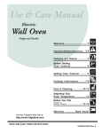
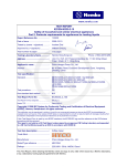
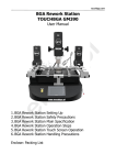
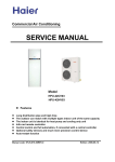
INSTALLATION AND MAINTENANCE MANUAL
GROUND SOURCE HEAT PUMP
WITH DC INVERTER (SIMPLE TYPE)
MODEL:
BWB-SS-7 DC
BWB-SS-9 DC
BWB-SS-12 DC BWB-SS-15 DC
- Please Read This Manual Before Using The Heat Pump -
Contents
General information for the installer
Transport and storage ............................................................................................................ 2
Installation .............................................................................................................................. 2
Overview of external structure ................................................................................................ 2
Inspection of the installation ....................................................................................................2
Copper tube size .....................................................................................................................2
Pump Data
Pump capacity diagrams ........................................................................................................ 3
How to adjust the rate of flow ................................................................................................. 4
Electrical connections
Wiring diagram ( 220v / 1 / 50 Hz ) ......................................................................................... 5
Wiring diagram ( 220v / 3 / 50 Hz ) ......................................................................................... 6
Wiring diagram ( 380v / 3 / 50 Hz ) ......................................................................................... 7
Control panel
Layout ....................................................................................................................................8
Explanation ............................................................................................................................8
Functions ...............................................................................................................................9
Symbols .................................................................................................................................9
Control
Menus ...................................................................................................................................... 10
Function detail .......................................................................................................................... 11
Alarm Messages ...................................................................................................................... 13
Circuit Board Picture For DC BWB-SS- 7 and DC BWB-SS-9................................................ 18
Circuit Board Picture For DC BWB-SS- 12 and DC BWB-SS-15 ........................................... 18
Water Sensor Resistance ......................................................................................................... 19
Component placement
Component positions 1 ............................................................................................................ 20
Component positions 2............................................................................................................. 21
Accessories and List of components
List of components .................................................................................................................... 22
Enclosed kit .............................................................................................................................. 22
Dimensions
Dimensions .............................................................................................................................. 23
Technical specifications
Technical specifications ........................................................................................................... 24
-1-
General information for the installer
Transport and storage
Inspection of the installation
The BWB-SS DC must be transported and stored
upright and dry. The BWB-SS DC may however be
carefully laid on its back when being moved into
a building.
Current regulations require the heating installation to
be inspected before it is commissioned. The inspection must be carried out by a suitably qualified person
and should be documented. The above applies to
closed heating systems. If the heat pump is replaced,
the installation must be inspected again.
H M flo w
4 9 (5 °C
0)
H o t w a te r5 1°C
0
-2
+2
1
0
R
0
0
+2
R
BWB-SS DC is placed on a firm base, preferably a
concrete floor or foundation. Install AWA-SS series
with its back to an outside wall, ideally in a room where
noise does not matter. If this is not possible, avoid
placing it against a wall behind a bedroom or other
room where noise may be a problem. Any wall that
backs on to a bedroom should be fitted with sound
insulation. Route pipes so they are not fixed to an internal wall that backs on to a bedroom or living room.
-2
H M flo 4
w 9 (5 °C
0)
H o t w a te r5 1°C
1
Installation
Overview of external structure
Copper tube size
Modle
Size
Gas
tube
Liquid
tube
+
+
+
+
+
+
+
+
-2-
BWBSS-7
BWBSS-9
BWBSS-12
BWBSS-15
5/ 8"
5/ 8"
3/ 4"
3/ 4"
3/ 8"
3/ 8"
1/ 2"
1/ 2"
Pump Data
Pump capacity diagrams
Wilo-Star-RS 25/6
(BWB-SS-7 DC)
6
[ Kpa
80
70
60
50
40
30
20
10
0
WILO RL-25/7.5
(BWB-SS-15 DC)
1
2
3
0.22
0
0.44
0.66
0.88
Flow
1.10
1.32
1.54
1.76
[L /s]
Available
pressure
[ Kpa
80
70
60
50
40
30
20
10
0
[
(BWB-SS-9 DC / BWB-SS-12 DC)
[
Wilo-Star-RS 25/8
Available
pressure
2
Tillgängligt tryck
1
3
0
0.28
0.56
-3-
0.84
1.12
1.4
1.68
Flow
1.96
2.24
[L /s]
Pump Data
How to adjust the rate of flow
The
pump
is
adjustable to adjust
the flow: 1, 2, or 3.
WILO RS-25/6
WILO RS-25/8
The
pump
is
adjustable to adjust
the flow: 1, 2, or 3.
WILO RL-25/7.5
Connecting The Water Tank Temperature Sensor
WTT
+
+
+
+
WTT
WTT=Water tank temperature sensor
-4-
Electrical connection
Wiring Diagram ( 220V / 1 / 50 HZ )
BWB-SS-7/9 DC ( 220V / 1 / 50 HZ )
EXHAUST TEMPERATURE
SENSOR
CN27
5
YELLOW
BLUE
OUTDOOR
MAIN PCB
CN8
CN6
CN1
CN10
CN2
CN4
RED
RED
BLACK
L
L
OFAN-L
OFAN-H
CN16-L
CN21-L
CN16-N
CN11
CN17
CN9
WHITE
P6
WHITE
P3
P1
P1
BLUE / WHITE
CN614
CN11-N
CN22
Compressor Frequency
Decrease For Protection
CN11-L
CN23
CFDT
CM
CN5
CN15
CN24
CN21-N
5
LP CSP
Compressor
Stop For Protection
WIRING DIAGRAM
EXPANSION
VALVE
BLACK
WHITE
4
CN2
CN7
CN8
L-IN CN1
N-IN CN4
CN11
CN13
CN17
PUMP
-5-
CN10
GROUND WATER OUTLET
TEMPERATURE
CN12
WATER TANK
TEMPERATURE
CN16
GROUND WATER INLET
TEMPERATURE
Electrical connection
Wiring Diagram ( 220V / 3 / 50 HZ )
BWB-SS-12/15 DC ( 220V / 3 / 50 HZ )
EXHAUST TEMPERATURE
SENSOR
CN14-L
CN14-N
CN16-N
CN16-L
CN22
CN21-L
CFDT
CN24
CN21-N
CN23
CN19-L
LP CSP
CN15
CN19-N
Compressor
Stop For Protection
5
CN5
CM
WIRING DIAGRAM
EXPANSION
VALVE
OUTDOOR
MAIN PCB
Compressor Frequency
Decrease For Protection
CN27
5
S
K1
COM
CN17
CN614
N-IN
REACTOR1
RED
YELLOW
L-IN
BLUE / WHITE
BLUE / WHITE
BLUE
NO
RED
60uf
CAP
Y/G
CN11 CN10
CN13 CN12
A
B
CN120
CN4
CN2
C
CN6
N
CN16
WHITE
PTC
BLACK
RED
BLUE
WHITE
BROWN
RED
L1
L3
L2
L1
CN15
4
CN2
CN7
CN8
L-IN CN1
CN10
GROUND WATER OUTLET
TEMPERATURE
CN12
WATER TANK
TEMPERATURE
CN16
GROUND WATER INLET
TEMPERATURE
BLUE / WHITE
N-IN CN4
CN11
CN13
CN17
PUMP
-6-
3 X 220V~230V
50Hz
Electrical connection
Wiring Diagram ( 380V / 3 / 50 HZ )
BWB-SS-12/15 DC ( 380V / 3 / 50 HZ )
EXHAUST TEMPERATURE
SENSOR
CN14-L
CN14-N
CN16-N
CN16-L
CN21-L
CN22
CN24
CN21-N
CN23
CFDT
CN19-L
LP CSP
CN15
CN19-N
Compressor
Stop For Protection
5
CN5
CM
WIRING DIAGRAM
EXPANSION
VALVE
OUTDOOR
MAIN PCB
Compressor Frequency
Decrease For Protection
CN27
5
S
K1
COM
CN17
CN614
N-IN
REACTOR1
RED
YELLOW
L-IN
BLUE / WHITE
BLUE / WHITE
RED
60uf
Y/G
CAP
CN11 CN10
CN13 CN12
A
B
CN120
CN4
CN2
C
CN6
N
CN16
BLUE / WHITE
BLUE
WHITE
PTC
BLACK
RED
WHITE
BROWN
RED
L1
N
L3
L2
L1
CN15
4
CN2
CN7
CN8
L-IN CN1
CN10
GROUND WATER OUTLET
TEMPERATURE
CN12
WATER TANK
TEMPERATURE
CN16
GROUND WATER INLET
TEMPERATURE
BLUE / WHITE
N-IN CN4
CN11
CN13
CN17
PUMP
-7-
3 X 380V~415V
50Hz
BLUE
NO
Control panel
Layout
Left
button
Up
button
Display
MONDAY 11:30
W. T. HEATING 37
Right
button
115%
Down
button
Power On/Off
•
One button pointing upwards marked with a up arrow
•
One button pointing downwards marked with a down arrow
•
One button pointing to the right marked with a right arrow
•
One button pointing to the left marked with a left arrow
•
One button pointing to the ON/OFF
Explanation
The control panel of BWB-SS DC series features a graphic display, five control buttons.
Beside the control panel you will find the User’s Manual, a short description of how to increase and reduce room
temperature, and a label with name and phone number of dealer.
MONDAY 11:30
W. T. HEATING 37
115%
Graphic display
-8-
Control panel
Functions
The control computer is operated with the help of a user friendly menu system that is displayed on the control
panel. There is a main menu and several sub-menus accessible from the main menu. The menus are
described in detail further down.
To be able to select the desired menu and increase or reduce preset values, you will use the five buttons.
The right-hand button on the control panel is used to open the desired menu.
The left-hand button is used to return to the previous menu.
The up and down buttons are used to navigate between the parameters of a menu.
A cursor (arrow) on the left-hand side of the display indicates which menu can be opened.
The up and down buttons are also used if you wish to increase or reduce a preset value.
When display at the interface, press button Right and Left at the same time for 5 seconds to lock the display.
All buttons are not available after lock is active, until press button Right and Left at the same time for 5
seconds to open the lock
Symbols
For you to know at a glance the actual operating mode of the heat pump,
one of the following symbols will be shown in the lower part of the display
depending on which part of the unit is working:
Indicates the status of warm water
production. If the symbol is empty,
warm water temperature is under
the setting temperature.
The heat pump is running.
(115) %
The running speed
percentage of compressor.
If the symbol is full, warm water
temperature reached to the setting
temperature
NOTICE
During heat pump running, if the water tank symbol twinkles once in every second, it means water tank
temperature is too low and it is in antifreezing protection. At the time warm water heating will forcibly start until
water temperature get to 20 ć, then go back to previous running mode.
-9-
Control
Menus
MENU
WORK WAY
STERILIZE
ADD. START
ADD DELAY
RESET
LANGUAGE
36(53)
WARM WT
12 (-9)
BR. IN
13
BR. OUT
11
CMP DIF
CONSTANT
0
HEATING GEAR
1
TIME SETTING
OFF
55
60 M
Parameter display or setting
Setting
Setting
range
Default
Warm WT
10-60ć
45ć
BRINE IN
-15-15ć
0ć
Explanation
Water tank setting temperature
Brine water inlet temperature
BRINE OUT
Brine water outlet temperature
WORK
WAY
ON/OFF
To let the heat pump runs ON/OFF or Constant way
ON/OFF˖heat pump will stop as soon as reach setting
water temperature
CONST.˖compressor will slow down when getting close
to setting water temperature
3-15ć
5ć
Compressor restart according to water temperature
degeneration
Factory setting is 5 degree, when water reach setting
temperature 45 degree, the compressor will stop, then
when the water temperature decrease 5 degree, the
compressor will restart.
ON/OFF
OFF
The function to kill the bacteria
ON˖function is available
OFF˖function is not available
55ć
Additional electrical heater start temperature
Only if the water temperature reaches 55 degree, the
additional electrical heater is allowed to start.
2-90
60min
Additional electrical heater delay time
After running of compressor 60 minutes, if the water
temperature still can not increase, the additional electrical
heater will start as supplementary
1-3
1
CMPDIF
STERILIZE
ADD
START
ADD
DELAY
HEATING
GEAR
CONSTANT
1. ON/OFF
2. Const.
10-60ć
0-8ć
3ć
Different gear has different compressor frequency range
Constant temperature setting
If the heat pump runs Const. way, when the water
temperature is 3 degree far from setting temperature, the
compressor will slow down. For example, the setting
water temperature is 55 degree, when water reaches 52
degree, the compressor start to slow down its speed.
- 10 -
Control
Function detail
Warm WT(10-60ć): water tank setting temperature
When water get to setting temperature heat pump will stop automatically if the work way is ON/OFF
When water is getting close to setting temperature heat pump will slow down if the work way is Const.
BRINE IN(10--15ć) Brine water inlet temperature
This parameter setting is adjustable from 10 degree to -15 degree, factory setting is 0 degree; when actual
water temperature less than setting temperature , heat pump will stop running; water pump runs 3 minutes
after it has been stop running 10 minutes each time. Heat pump will restart when actual water temperature
higher than setting temperature 2 degree.
BRINE OUT: Brine water outlet temperature
Only display real water temperature for reference.
CMPDIF: compressor restart according to temperature degeneration.
The parameter is adjustable from 3 to 15 degree; Factory setting is 5 degree, when water reach setting
temperature 45 degree, the compressor will stop, then when the water temperature decrease 5 degree, the
compressor will restart.
HEATING GEAR: compressor frequency range
It is adjustable from gear 1 to 3, factory setting is gear 1; the higher gear setting, the high compressor
frequency will be ;
CONSTANT(0-8ć): Constant temperature setting
Factory setting is 3 degree.
If the heat pump runs Const. way, when the water temperature is 3 degree far from setting temperature, the
compressor will slow down. For example, the setting water temperature is 55 degree, when water reaches 52
degree, the compressor start to slow down its speed.
TIME SETTING
TIME SETTING
TIMER 2 ON
10:00
DATE
DAY
TIME
TIMER 1 ON
2011-12-19
MONDAY
15:32
TIMER 2 OFF
18:30
8:00
TIMER 1 OFF
11:00
DATE
To display year, month, date.
DAY
TO display day of week.
TIME
To display time, or adjust time.
Double timers for heat pump
When you choose the symbol ‘¥’, the Auto start function of water tank heating is active. Select ‘͖’to cancel this
function. If this function is active the heat pump will start heating water tank at the time of your choosing.
When you choose the symbol ‘¥’, the Auto stop function of water tank heating is active. Select ‘͖’to cancel this
function. If this function is active the heat pump will stop heating water tank at the time.
Please do not set TIME ON and TIME OFF to be same data.
- 11 -
Control
Function detail
WORK WAY: ON/OFF mode or Const. mode (inverter)
WORK WAY
ON / OFF
CONSTANT
ON/OFF mode ˖compressor stop running as soon as reach setting water temperature
Const. mode: constant water temperature mode, factory setting is 3 degree; if the heat pump runs Const. way,
when the water temperature is 3 degree far from setting temperature, the compressor will slow down. For
example, the setting water temperature is 55 degree, when water reaches 52 degree, the compressor start to
slow down its speed.
STERILIZE: function to kill the bacteria in period
ON: function is available; each 15 days the heat pump will execute sterilize once and the water temperature
will up to 60 degree; during the 15 days, if any day of the period the water has reach the 60 degree, then the
calculation for the period will be restart; during the time of bacteria killing, if 3 hours later the water still can not
up to 60 degree, sterilize action will quit automatically.
OFF: function is closed.
ADD START(10-60ć): additional electrical heater start temperature
Factory setting is 55degree, only if the water temperature reaches 55 degree; the additional electrical heater is
allowed to start.
ADD DELAY (2-90 minute): Additional electrical heater delay time
Factory setting is 60 minutes.
After running of compressor 60 minutes, if the water temperature still can not increase, the additional electrical
heater will start as supplementary
RESET:
Press button right for 5 seconds, all the settings will go back to factory setting (default)
Language:
English, Norwegian and Swedish.
LANGUAGE
ENGLISH
NORSK
SVENSKA
- 12 -
Control
Alarm Messages
In the event of an alarm message, try to re-start the unit with the safety switch.
If this does not work, try to solve the problem with the help of the table below. Call your installation contractor if
you need help.
Table : Alarm Messages
Alarm
DISPLAY EEPROM
DISPLAY-TRANSITION COMMUNICATE
TRANSITION EEPROM
TRANSITION-MAIN COMMUNICATE
MAIN-MODULE COMMUNICATE
Explanation
EEPROM reading failure from display
The communications failure between display board and
transition circuit board
EEPROM reading error from transition circuit board
The communications error between transition circuit
board and main circuit board
The communications error between main circuit board
and module
MODULE VOLTAGE OVER
Outdoor module voltage over-low error
IPM MODULE
IPM module error
CMP TOP OVER
Compressor top temperature over
CMP TEMP.
Compressor exhausts temperature sensor error
WARM WATER TEMP.
Water tank temperature sensor error
HIGH PRESS
Pressure over high
LOW PRESS
Pressure over low
WARM WATER TEMP. TOO LOW
The water tank temperature is too low
BRING IN TEMP.
The brine water inlet temperature sensor error
BRING OUT TEMP.
The brine water outlet temperature sensor error
- 13 -
Control
Alarm Messages
The cause of alarm ‘IPM MODULE’ could be:
1ǃThe communications between Module and outdoor main circuit board is jamming;
2ǃModule is jamming and can not detect current or compressor;
3ǃModule can not start compressor;
4ǃModule’s rated 15VDC voltage is not steady
5ǃModule’s current overload˗
How to do:
1. Please check if all terminals connections among circuit boards were good, whether some of the wire
damaged;
2. Please check if the compressor wire connection loose (on the top of compressor);
3. Please measure each two of the connections (on the top of compressor)’s resistance, if the resistance are
always the same, means the compressor is fine. there 3 connections on the top of compressor , you need
to measure each two 's resistance, for example , let 's say the connections are A, B, C, then you need to
measure the resistance of AB, AC, BC;
4. please check wire connection between the outdoor circuit board and module; see the follow picture
5. Check the DC voltage between terminal P and N if normal, the DC voltage should be:
BWB-SS-7 / 9 DC: 380VDC
BWB-SS-12 / 15 DC (single phase): 280VDC
BWB -SS-12 / 15 DC (trinal phase): 540VDC
N
P
- 14 -
Control
Alarm Messages
6. check the if DC voltage between A(first wire) and B(third wire) is normal, it should be 13.5V ~16.5V
A
B
The cause of alarm ‘TRANSITION-MAIN COMMUNICATE’ could be:
1. The connection between transition circuit board and main circuit board is wrong;
2. The connection between transition circuit board and main circuit board is not good, such as had creepage;
3. The transition circuit board or main circuit board was damaged.
How to do˖
1. Check the connection wire between transition circuit board and main circuit board, their live wires, zero
curves was connected correctly;
2. Check the connection wire between transition circuit board and main circuit board, the wire must be less
than 20 meters, the terminals must be water- proof;
3. If the connection is fine, then the cause could be the transition circuit board or main circuit board, please
check their lights.
The cause of alarm ‘MODULE VOLTAGE OVER’ could be:
1. Water flow was not enough;
2. One of the sensors got problem;
3. Ambient temperature was too high
How to do:
1. Check if the water flow was not enough;
2. Check all the sensors if they are normal.
- 15 -
Control
Alarm Messages
The cause of alarm ‘CMP TOP OVER’ could be:
1. Water flow was not enough;
2. Refrigerant was not enough
3. Ambient temperature was too high;
How to do:
1. Check if the water flow was not enough, so that the heat exchange efficiency was not good;
2. Check the refrigerant quantity, and make sure the system has not any leak. ;
The cause of ‘LOW PRESS’ could be ˖
1. The refrigerant was not enough
2. The connection of low pressure switch was loose, or the switch was broken;
3. The outdoor fan can not run
How to do:
1. Check if there any place leak refrigerant, especially on the connections valves;
2. Check if the wire connection of low pressure switch was ok, or replace a new low pressure
switch;
3. Check if the outdoor unit’s fan was running, if not, please check if the fan was normal
The cause of ‘HIGH PRESS’ could be ˖
1. The water flow was not enough;
2. The high pressure switch’s connection was not good; or the switch was broken;
3. The ambient temperature was too high.
How to do:
1. Always ensure enough water flow; otherwise the flow switch can not open;
2. Check if the wire connection of high pressure switch was ok, or replace a new one;
The cause of alarm ‘WARM WATER TEMP.’ could be:
1. The connection of water tank temperature sensor was loose;
2. The water tank temperature sensor was broken;
How to do:
1. Find the connection and make sure it is fine;
2. As per resistance table of the sensor, please measure the sensor’s resistance, to judge the
sensor was good or bad; replace a new one if the sensor get problem.
- 16 -
Control
Alarm Messages
The cause of alarm ‘CMP TEMP.’ could be:
1. The connection of compressor exhaust air temperature sensor was loose;
2. The compressor exhaust air temperature sensor was broken;
How to do:
1. Find the connection and make sure it is fine;
2. As per resistance table of the sensor, please measure the sensor’s resistance, to judge the
sensor was good or bad; replace a new one if the sensor get problem.
The cause of alarm ‘BRING IN TEMP.’ could be:
1. The connection of brine water inlet temperature sensor was loose;
2. The brine water inlet temperature sensor was broken;
How to do:
1. Find the connection and make sure it is fine;
2. As per resistance table of the sensor, please measure the sensor’s resistance, to judge the
sensor was good or bad; replace a new one if the sensor get problem.
The cause of alarm ‘BRING OUT TEMP.’ could be:
1. The connection of brine water outlet temperature sensor was loose;
2. The brine water outlet temperature sensor was broken;
How to do:
1. Find the connection and make sure it is fine;
2. As per resistance table of the sensor, please measure the sensor’s resistance, to judge the
sensor was good or bad; replace a new one if the sensor get problem.
- 17 -
Control
Circuit Board Picture For DC BWB-SS- 7 and DC BWB-SS-9
Display
Transition circuit board
Module
Main circuit board
Circuit Board Picture For DC BWB-SS- 12 and DC BWB-SS-15
Display
Transition circuit board
Module
Main circuit board
- 18 -
Power board
Control
Water Sensor Resistance
water sensor resistance
T
-20
-19
-18
-17
-16
-15
-14
-13
-12
-11
-10
-9
-8
-7
-6
-5
-4
-3
-2
-1
0
1
2
3
4
5
6
7
8
9
10
11
12
13
14
15
16
17
18
19
R
115.266
108.146
101.517
96.3423
89.5865
84.219
79.311
74.536
70.1698
66.0898
62.2756
58.7079
56.3694
52.2438
49.3161
46.5725
44
41.5878
39.8239
37.1988
35.2024
33.3269
31.5635
29.9058
28.3459
26.8778
25.4954
24.1932
22.5662
21.8094
20.7184
19.6891
18.7177
17.8005
16.9341
16.1156
15.3418
14.6181
13.918
13.2631
AD
16
17
18
19
21
22
23
24
26
27
29
30
31
34
35
37
39
41
42
45
47
49
51
54
56
58
61
63
67
68
71
74
76
79
82
85
87
90
93
96
Unitġ §--Kȍ ˄water/ambient/pipe sensor)
T
R
AD
T
R
AD
20
60
12.6431
99
2.35774 197
21
61
12.0561
102
2.27249 198
22
62
11.5
105
2.19073 200
23
63
10.9731
107
2.11241 202
24
64
10.4736
110
2.03732 203
25
65
10
113
1.96532 205
26
66
9.55074
116
1.89627 206
27
67
9.12445
119
1.83003 207
28
68
8.71983
122
1.76647 209
29
69
8.33566
125
1.70547 210
30
70
7.97078
128
1.64691 211
31
71
7.62411
131
1.59068 212
32
72
7.29464
133
1.53668 214
33
73
6.98142
136
1.48481 215
34
74
6.68355
139
1.43498 216
35
75
6.40021
142
1.38703 217
36
76
6.13059
144
1.34105 218
37
77
5.87359
147
1.29078 219
38
78
5.62961
150
1.25423 220
39
79
5.39689
152
1.2133
221
40
80
5.17519
155
1.17393 222
41
81
4.96392
157
1.13604 223
42
82
4.76253
160
1.09958 224
43
83
4.5705
162
1.06448 225
44
84
4.38736
165
1.03069 226
45
85
4.21263
167
0.99815 226
46
86
4.04589
169
0.96681 227
47
87
3.88673
172
0.93662 228
48
88
3.73476
174
0.90753 229
49
89
3.58962
176
0.8795
229
50
90
3.45097
178
0.85248 230
51
91
3.31847
180
0.82643 231
52
92
3.19183
182
0.80132 231
53
93
3.07075
184
0.77709 232
2.95896
186
0.75373 233
54
94
55
95
2.84421
188
0.73119 233
56
96
2.73823
190
0.70944 234
2.63682
192
0.68844 234
57
97
58
98
2.53973
193
0.66818 235
59
99
2.44677
195
0.64862 236
- 19 -
T
100
101
102
103
104
105
106
107
108
109
110
111
112
113
114
115
116
117
118
119
120
121
122
123
124
125
126
127
128
129
130
131
132
133
134
135
136
137
138
139
R
0.62973
0.61148
0.59386
0.57683
0.56038
0.54448
0.52912
0.51426
0.49989
0.486
0.47256
0.45957
0.44699
0.43482
0.42304
0.41164
0.4006
0.38991
0.37956
0.36954
0.35982
0.35042
0.3413
0.33246
0.3239
0.31559
0.30754
0.29974
0.29216
0.28482
0.2777
0.27078
0.26408
0.25757
0.25125
0.24512
0.23916
0.23338
0.22776
0.22231
AD
236
237
237
237
238
238
239
239
240
240
240
241
241
241
242
242
242
243
243
243
244
244
244
244
245
245
245
245
246
246
246
246
246
247
247
247
247
247
247
248
Component placement
Component Positions 1
Please Note : The picture for reference only !
1
2
3
4
6
5
7
10
9
20
19
8
18
16
15
17
11
21
12
13
14
- 20 -
Component placement
Component Positions 2
Please Note : The picture for reference only !
BWB-SS-7 / 9 DC
24 28 29 25
23
22
27
+
+
+
+
26
+
+
36
35
+
37
+ +
+
+
32A
+
33
+
+
+
+
+
+
30
+
+
E28077
ROHS
34
31
BWB-SS-12 / 15 DC
24 28 29 25
23
22
+
+
+
+
26
27
37
36
+
+
+
+
32B
+
+
+
+
+ + +
+
+
+
31
+
+
+
+
+
3
4
+
0057W
34
+
+
+ + +
38
104
A
104
+
E28077
ROHS
104
A
104
+
+
+
+
A
+
+
+
+
10 4
104
+
+
+
+
+
+
+
+
+
+
+
+
30
35
39
- 21 -
40
33
Accessories and List of components
Enclosed kit
41
44
43
42
46
45
List of components
Please Note : The List for reference only !
1
2
3
4
Plastic top board
Control panel
Left side board
Right side board
24
25
26
27
28
29
30
31
32A
32B
High pressure needle valve
Low pressure needle valve
Brine Out Pipe Connection Ø 28 mm
Brine In Pipe Connection Ø 28 mm
Temperature sensor connection hole
Power cord connection hole
Transition Circuit board
Main circuit board
PFC
Capacitor
33
34
Module
Electrical Bridge
35
36
Transformer
Reactance
Terminal Connector
Power Board
AC contactor
5
6
7
8
9
10
11
12
Front board
Handles
Stainless steel adjustable feet
Pillars
Structural framing
Electrical Box
Compressor
Fixing Board For Compressor
13
14
15
16
Oil tank
Evaporator
Water pump ( Brine pump )
Expansion valve
17
Drying filter
37
38
39
18
High pressure pressostat 1
40
PTC (Thermister)
19
20
High pressure pressostat 2
Low pressure pressostat
41
42
Allen key
Copper connectors
21
22
23
Draining connector
High pressure valve
Low pressure valve
43
44
45
46
Drainpipe
Draining connector
10K Copper Temperature Sensor ( for Water Tank )
Temperature Sensor Connections
- 22 -
Dimensions
Dimensions
970mm
80mm
m
600m
60mm
685
mm
- 23 -
Technical specifications
Technical specifications
IP 21
Refrigerant : R410A
Ground Source Heat
Pump With DC inverter
Ground Source Heat
Pump With DC inverter
Ground Source Heat
Pump With DC inverter
Model:
Indoor unit
Model:
Indoor unit
Model:
Indoor unit
Heating Capacity
Heating Power Input
Power Supply
Rated Current
Max.Input Power
Max.Discharge Pressure
Max.SuctionPressure
Refrigerant
Brine Pump Flux
Noise
Net Weight
BWB-SS-7(DC)
7050W
1753W
220V/50Hz/1Ph
8.0A
2850W
4.0MPa
0.95MPa
R410A /1.6kg
1.8m/h
<48dB(A)
80kg
3
BWB-SS-9(DC)
Heating Capacity
Heating Power Input
Power Supply
Rated Current
Max.Input Power
Max.Discharge Pressure
Max.SuctionPressure
Refrigerant
Brine Pump Flux
Noise
Net Weight
9080W
2253W
220V/50Hz/1Ph
10.3A
3050W
4.0MPa
0.95MPa
R410A /1.75kg
1.8m/h
<49dB(A)
84kg
3
RoHS
Ground Source Heat
Pump With DC inverter
Ground Source Heat
Pump With DC inverter
Model:
Indoor unit
Model:
Indoor unit
Heating Capacity
Heating Power Input
Power Supply
Rated Current
Max.Input Power
Max.Discharge Pressure
Max.SuctionPressure
Refrigerant
Brine Pump Flux
Noise
Net Weight
14800W
3718W
220V/50Hz/3Ph
9.7A
5450W
4.0MPa
0.95MPa
R410A /2.9kg
2.3m/h
<51dB(A)
110kg
3
BWB-SS-15(DC)
Heating Capacity
Heating Power Input
Power Supply
Rated Current
Max.Input Power
Max.Discharge Pressure
Max.SuctionPressure
Refrigerant
Brine Pump Flux
Noise
Net Weight
RoHS
14750W
3706W
380V/50Hz/3Ph
6.5A
5450W
4.0MPa
0.95MPa
R410A /2.75kg
2.3m/h
<51dB(A)
110kg
3
RoHS
- 24 -
11980W
2987W
220V/50Hz/3Ph
8.2A
5300W
4.0MPa
0.95MPa
R410A /2.5kg
2.05m/h
<50dB(A)
105kg
3
RoHS
RoHS
BWB-SS-15(DC)
Heating Capacity
Heating Power Input
Power Supply
Rated Current
Max.Input Power
Max.Discharge Pressure
Max.SuctionPressure
Refrigerant
Brine Pump Flux
Noise
Net Weight
BWB-SS-12(DC)