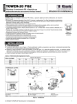
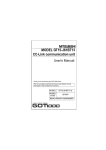
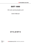
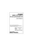
1
TOWER-20 PG2 PowerG, Wireless High‐security PIR Motion Outdoor Mirror Detector with Anti‐masking Installation Instructions 1. INTRODUCTION The TOWER-20 PG2 is a 2-way, wireless outdoor digital mirror PIR detector which includes the following features: Patented 8 independent quad PIR detectors (Octa-QUAD) operating in true Quad configuration (patented) with true motion recognition (TMR) processing for each of the 8 PIR detectors, as well as central motion processing that distinguishes between moving intruders and trees and bushes in motion. Advanced Obsidian Black MirrorTM optics (patent pending). Optimum performance even in poor weather conditions such as snow, rain, dust, wind and direct sunlight Tamper protection prevents opening and removal from wall PowerG two-way Frequency Hopping Spread Spectrum FHSS-TDMA technology - provides robustness and reliability that is closer than ever to wired systems Built-in link quality indicators enable installer to check signal quality without physically approaching the control panel, thus making installation faster and easier. Robust housing with recessed window. Smart anti masking distinguishes between masking spray and rain. Alarm LED is visible in sunlight. Automatic termination of walk-test after 15 minutes. Microprocessor-controlled temperature compensation. Immunity to pets weighing up to 18 Kg (40ib), not pet alley Built-in swivel bracket Figure 1. General View 2. INSTALLATION 2.1 Installation A. Bracket installation (see Figure 2). Fix the bracket firmly on a stable wall or pillar. The orientation of the fixed bracket must be as parallel as possible to the surveyed ground surface. B. Adjust the detector's horizontal and vertical angles (see Figure 3), according to the surveyed ground surface. The vertical angle indicator position for various installation height and coverage distance combinations is detailed in Table 1 (the information refers to a relatively flat surveyed area. Verify the vertical adjustment by walk-test). C. Fasten the detector to the bracket (see Figure 2 step 4). Table 1 - Vertical Adjustment Reference Coverage Distance Mounting Height 2m / 6.7ft 4m / 13ft 6m / 20ft 8m / 26ft 10m / 33 ft 12m / 39 ft 3.0m / 10 ft 1 2 2 3 3 2.5m / 8 ft 1 1 2 3 4 4 2.0m / 7 ft 1 2 3 4 5 5 1.5m / 5 ft 2 3 4 5 - Correct Installation Incorrect Installation A. Mark drilling point B. For wall tamper C. Drill D. Fasten Note: The 2 screw holes enable adjustment of the bracket on the wall, if needed, following the walk test. E. Three long screws F. Two short screws Figure 2 - Installation D-304046 TOWER-20 PG2 Installation Instructions 1 HORIZONTAL ADJUSTMENT (-45 to +45) VERTICAL ADJUSTMENT (0 to -10 in 2.5 clicks / steps) COVER CLOSURE 1. Release locking 6. Lock 2. Adjust 7. Turn cover and push slider 3. Lock 8 & 9. Put back cover 4. Release locking 10. Secure with screw 5. Adjust A. Vertical angle steps Figure 3 - Adjustment and Cover Closure 2 D-304046 TOWER-20 PG2 Installation Instructions 2.2 Battery Insertion It is recommended to perform the first batteries insertion on a flat surface (see Figure 4). After battery insertion, the LED will flash for 60 seconds and then the detector will enter a 15 minutes' local diagnostic mode. A. Tamper switch B. Press firmly to release the bracket C. 3 screws Figure 4 – Battery Insertion 2.3. Enrollment Refer to the PowerMaster control panel's Installer Guide and follow the procedure under the "02:ZONES/DEVICES" option of the Installer Menu. A general description of the procedure is provided in the following flow chart. Step 1 Step 2 Enter the Installer menu and select “02:ZONES/DEVICES” Select "ADD NEW DEVICE" See Note 1 02:ZONES/DEVICES Step 3 ADD NEW DEVICES Step 4 Enroll the device (see Figure 5) or Select a detector number for enter the device ID the new flood detector ENROLL NOW or Z14:Motion Sens ID No. 130-XXXX ENTR ID:XXX-XXXX MODIFY DEVICES Step 5 Step 6 Configure Location, Zone Type & Chime parameters Z14.LOCATION Z14.ZONE TYPE Step 7 Enter PARTITIONS. See Note 2 Z14.PARTITIONS Assign partitions to the detector by , pressing the buttons on the and/or panel Z14:P1 P2 P3 Z14.SET CHIME means scroll and select Notes: [1] If the detector is already enrolled you can configure the detector parameters and assign partitions via the “Modify Devices” option – see Step 2. [2] PARTITIONS will appear only if PARTITIONING was previously enabled in a panel that supports the Partitioning feature (for further details, see "Partitioning" in the PowerMaster Installer Guide). D-304046 TOWER-20 PG2 Installation Instructions 3 2.4. Configuring the Detector Parameters Enter the DEVICE SETTINGS menu and follow the configuration instructions for the TOWER-20 PG2 PIR detector as described below. Option Configuration Instructions Define whether or not to activate the alarm LED indication. ALARM LED Optional settings: ON (default) and OFF. PIR SENSITIIVITY Define if the detector operates at regular or high PIR sensitivity, or that at least one detection zone must be crossed before an alarm is triggered (One Region). Optional settings: LOW (default), HIGH and One Region. Note: For EN compliance, the detector should be set to "One Region". DISARM ACTIVITY Define whether or not to set the activity time during Disarm mode. Optional settings: NOT Active (default), YES – no delay, YES + 5s delay, YES + 15s delay, YES + 30s delay, YES + 1m delay, YES + 2m delay, YES + 5m delay, YES + 10m delay, YES + 20m delay and YES + 60m delay. OUTDOOR ANTI-M Enable or disable the outdoor anti-masking feature. Optional settings: Disabled (default) and Enabled. Define whether motion alarms are always enabled or only when dark (at night). ALARM Hours Optional settings: Day and Night (default) and Night only. 2.5 Local Diagnostic Test A. Set the detector in local diagnostic mode, as follows: Open the detector’s bottom cover (see Figure 4, steps 1 - 3) and then press and release the tamper switch (see Figure 5). The LED will flash for 60 seconds and then the detector will enter into 15 minutes' local diagnostic mode. Note: The detector automatically enters into 15 minutes' local diagnostic mode after battery installation or Tamper switch recovery. B. Adjust the detector in the horizontal plane to cover the required protected area. C. Walk into the detectors’ field of view. Adjust the vertical plane to receive the maximum number of detections when crossing the entire 90 pattern. Verify that the LED blinks each time your motion is detected, as you cross one Quad PIR. Then verify that the LED lights steadily for 2 seconds as you cross the next adjacent Quad PIR. After alarm indication, the LED blinks three times and provides the received signal strength indication (see Table 2). Table 2 – Received Signal Strength Indication LED response Reception Green LED blinks Strong Orange LED blinks Good Red LED blinks Poor No blinks No communication IMPORTANT! Reliable reception must be assured. Therefore, "poor" signal strength is not acceptable. If you receive a "poor" signal from the detector, re-locate it and re-test until a "Good" or "Strong" signal strength is received. Note: For detailed Diagnostics Test instructions refer to the control panel Installer's Guide The LED blinking, described above, is operative only in Local diagnostic mode. Upon each full detection (LED lights steadily for 2 seconds), the control panel receives the alarm. If required, perform the detector's horizontal / vertical adjustments (see section 2.1 and Figure 3). Important! Instruct the user to perform a walk test at least once a week, to verify proper operation of the detector. D. Place a piece of cardboard on the detector’s front side to deliberately mask the optical window. Verify that after 2 minutes, the yellow LED lights continuously (see Table 3 below) and the alarm control panel receives the masking alarm. E. Remove the masking from the detector’s front side. Verify that the LED turns off. Table 3 - LED operation LED Indications Red LED blinks Event Stabilization (warm-up 60 sec) Red LED ON 0.2 sec. Tamper open / close Red LED blinks twice One quad PIR detection in diagnostic mode Red LED on 2 sec. Intruder alarm Yellow LED on AM detection – diagnostic mode Yellow LED blinks slowly (0.2 sec. ON, 30 sec. OFF) AM detection – Normal mode Note: After detection, the detector disables itself to save battery power. It reverts to the ready state if there is no subsequent detection throughout the following 2-minute period. 4 D-304046 TOWER-20 PG2 Installation Instructions A. LED B. Enroll button C. Tamper switch Figure 5. Tower-20 PG2 3. COMPLIANCE WITH STANDARDS Compliance with Standards The TOWER-20 PG2 is designed to comply with the following standards: Europe (CE): EN 300220, EN 301489, EN 60950, EN 50130-4, EN 50130-5, EN 50131-2-2, EN 50131-6, EN 50131-1 Grade 3 Class IV The TOWER-20 PG2 is compatible with the RTTE requirements - Directive 1999/5/EC of the European Parliament and of the Council of 9 March 1999 and EN50131-1 Grade 2 Class IV. UK: This product is suitable for use in systems installed to conform to PD6662:2010 at Grade 2 and environmental class 4. DD243 and BS8243 USA: CFR 47 Part 15 (FCC) Canada: RSS 210 The Power G peripheral devices have two- way communication functionality, providing additional benefits as described in the technical brochure. This functionality has not been tested to comply with the respective technical requirements and should therefore be considered outside the scope of the product’s certification. EN 50131-1 Security Grade EN 50131-1 Environmental Class Grade 3 Class IV FCC Compliance Statement This device has been tested and found to comply with the limits for a Class B digital device, pursuant to Part 15 of the FCC Rules. These limits are designed to provide reasonable protection against harmful interference in residential installations. This equipment generates uses and can radiate radio frequency energy and, if not installed and used in accordance with the instructions, may cause harmful interference to radio and television reception. However, there is no guarantee that interference will not occur in a particular installation. If this device does cause such interference, which can be verified by turning the device off and on, the user is encouraged to eliminate the interference by one or more of the following measures: – Re-orient or re-locate the receiving antenna. – Increase the distance between the device and the receiver. – Connect the device to an outlet on a circuit different from the one that supplies power to the receiver. – Consult the dealer or an experienced radio/TV technician. WARNING! Changes or modifications to this unit not expressly approved by the party responsible for compliance could void the user’s authority to operate the equipment. This device complies with FCC Rules Part 15 and with Industry Canada licence-exempt RSS standard(s). Operation is subject to two conditions: (1) This device may not cause harmful interference, and (2) this device must accept any interference that may be received or that may cause undesired operation. Le present appareil est conforme aux CNR d'Industrie Canada applicables aux appareils radio exempts de licence. L'exploitation est autorisee aux deux conditions suivantes :(1) l'appareil ne doit pas produire de brouillage, et (2) l'utilisateur de l'appareil doit accepter tout brouillage radioelectrique subi, meme si le brouillage est susceptible d'en compromettre le fonctionnement. The technical documentation as required by the European Conformity Assessment procedure is kept at: UNIT 6 MADINGLEY COURT CHIPPENHAM DRIVE KINGSTON MILTON KEYNES MK10 0BZ. Telephone number: 0870 7300800, Fax number: 0870 7300801 W.E.E.E. Product Recycling Declaration For information regarding the recycling of this product you must contact the company from which you orignially purchased it. If you are discarding this product and not returning it for repair then you must ensure that it is returned as identified by your supplier. This product is not to be thrown away with everyday waste. Directive 2002/96/EC Waste Electrical and Electronic Equipment. D-304046 TOWER-20 PG2 Installation Instructions 5 APPENDIX: SPECIFICATIONS OPTICAL Black Mirror Max. Coverage Detector Technology At least 12 m (40 ft) / 90° 8 independent quad PIR detectors operating in true Quad configuration A. Top view B. Side view of each detector Pet Immunity ELECTRICAL Input Power Battery Life (for typical use) Low Battery Threshold WIRELESS Frequency Band (MHz) Communication Protocol Tamper Alert MOUNTING Mounting Type Mounting Height Horizontal Adjustment Vertical Adjustment ENVIRONMENTAL Operating Temperatures Storage Temperatures Humidity White Light Immunity PHYSICAL Size (H x L x W) Weight (with battery) Color PATENTS WARRANTY Figure 6. Coverage Pattern Up to 18 Kg (40 lb) Two 3V CR123A Lithium batteries Caution! Risk of explosion if battery is replaced by an incorrect type. Dispose of used battery according to the manufacturer's instructions. 3 years 4.0 V Europe and rest of world: 433-434, 868-869 USA: 912-919 PowerG Reported when a tamper event occurs and in any subsequent message, until the tamper switch is restored Wall mounting 1.5 – 3.0 m (5 – 10 ft). -45° to +45°, in 5° steps 0° to -10°, in 2.5° steps -35°C to 60°C (-31°F to 140°F) -35°C to 60°C (-31°F to 140°F) 95% max. Above 25000 lux 157 x 147 x 124 mm (6-3/16 x 5-13/16 x 4-7/8”) 600 g (21 oz). White or gray U.S. Patents 7250605 6818881 5693943 (other patents pending) Visonic Limited (the “Manufacturer") warrants this product only (the "Product") to the original purchaser only (the “Purchaser”) against defective workmanship and materials under normal use of the Product for a period of twelve (12) months from the date of shipment by the Manufacturer. This Warranty is absolutely conditional upon the Product having been properly installed, maintained and operated under conditions of normal use in accordance with the Manufacturers recommended installation and operation instructions. Products which have become defective for any other reason, according to the Manufacturers discretion, such as improper installation, failure to follow recommended installation and operational instructions, neglect, willful damage, misuse or vandalism, accidental damage, alteration or tampering, or repair by anyone other than the manufacturer, are not covered by this Warranty. The Manufacturer does not represent that this Product may not be compromised and/or circumvented or that the Product will prevent any death and/or personal injury and/or damage to property resulting from burglary, robbery, fire or otherwise, or that the Product will in all cases provide adequate warning or protection. The Product, properly installed and maintained, only reduces the risk of such events without warning and it is not a guarantee or insurance that such events will not occur. THIS WARRANTY IS EXCLUSIVE AND EXPRESSLY IN LIEU OF ALL OTHER WARRANTIES, OBLIGATIONS OR LIABILITIES, WHETHER WRITTEN, ORAL, EXPRESS OR IMPLIED, INCLUDING ANY WARRANTY OF MERCHANTABILITY OR FITNESS FOR A PARTICULAR PURPOSE, OR OTHERWISE. IN NO CASE SHALL THE MANUFACTURER BE LIABLE TO ANYONE FOR ANY CONSEQUENTIAL OR INCIDENTAL DAMAGES FOR BREACH OF THIS WARRANTY OR ANY OTHER WARRANTIES WHATSOEVER, AS AFORESAID. THE MANUFACTURER SHALL IN NO EVENT BE LIABLE FOR ANY SPECIAL, INDIRECT, INCIDENTAL, CONSEQUENTIAL OR PUNITIVE DAMAGES OR FOR LOSS, DAMAGE, OR EXPENSE, INCLUDING LOSS OF USE, PROFITS, REVENUE, OR GOODWILL, DIRECTLY OR INDIRECTLY ARISING FROM PURCHASER’S USE OR INABILITY TO USE THE PRODUCT, OR FOR LOSS OR DESTRUCTION OF OTHER PROPERTY OR FROM ANY OTHER CAUSE, EVEN IF MANUFACTURER HAS BEEN ADVISED OF THE POSSIBILITY OF SUCH DAMAGE. THE MANUFACTURER SHALL HAVE NO LIABILITY FOR ANY DEATH, PERSONAL AND/OR BODILY INJURY AND/OR DAMAGE TO PROPERTY OR OTHER LOSS WHETHER DIRECT, INDIRECT, INCIDENTAL, CONSEQUENTIAL OR OTHERWISE, BASED ON A CLAIM THAT THE PRODUCT FAILED TO FUNCTION. However, if the Manufacturer is held liable, whether directly or indirectly, for any loss or damage arising under this limited warranty, THE MANUFACTURER'S MAXIMUM LIABILITY (IF ANY) SHALL NOT IN ANY CASE EXCEED THE PURCHASE PRICE OF THE PRODUCT, which shall be fixed as liquidated damages and not as a penalty, and shall be the complete and exclusive remedy against the Manufacturer. When accepting the delivery of the Product, the Purchaser agrees to the said conditions of sale and warranty and he recognizes having been informed of. Some jurisdictions do not allow the exclusion or limitation of incidental or consequential damages, so these limitations may not apply under certain circumstances. The Manufacturer shall be under no liability whatsoever arising out of the corruption and/or malfunctioning of any telecommunication or electronic equipment or any programs. The Manufacturers obligations under this Warranty are limited solely to repair and/or replace at the Manufacturer’s discretion any Product or part thereof that may prove defective. Any repair and/or replacement shall not extend the original Warranty period. The Manufacturer shall not be responsible for dismantling and/or reinstallation costs. To exercise this Warranty the Product must be returned to the Manufacturer freight pre-paid and insured. All freight and insurance costs are the responsibility of the Purchaser and are not included in this Warranty. This warranty shall not be modified, varied or extended, and the Manufacturer does not authorize any person to act on its behalf in the modification, variation or extension of this warranty. This warranty shall apply to the Product only. All products, accessories or attachments of others used in conjunction with the Product, including batteries, shall be covered solely by their own warranty, if any. The Manufacturer shall not be liable for any damage or loss whatsoever, whether directly, indirectly, incidentally, consequentially or otherwise, caused by the malfunction of the Product due to products, accessories, or attachments of others, including batteries, used in conjunction with the Products. This Warranty is exclusive to the original Purchaser and is not assignable. This Warranty is in addition to and does not affect your legal rights. Any provision in this warranty which is contrary to the Law in the state or country were the Product is supplied shall not apply. Warning: The user must follow the Manufacturer’s installation and operational instructions including testing the Product and its whole system at least once a week and to take all necessary precautions for his/her safety and the protection of his/her property. 1/08 VISONIC LTD. (ISRAEL): P.O.B 22020 TEL-AVIV 61220 ISRAEL. PHONE: (972-3) 645-6789, FAX: (972-3) 645-6788 VISONIC INC. (U.S.A.): 65 WEST DUDLEY TOWN ROAD, BLOOMFIELD CT. 06002-1376. PHONE: (860) 243-0833, (800) 223-0020. FAX: (860) 242-8094 VISONIC LTD. (UK): UNIT 6 MADINGLEY COURT CHIPPENHAM DRIVE KINGSTON MILTON KEYNES MK10 0BZ. TEL.: +44(0)845 0755800 FAX: +44(0)845 0755801 PRODUCT SUPPORT: +44(0)845 755802 VISONIC IBERICA: ISLA DE PALMA, 32 NAVE 7, POLÍGONO INDUSTRIAL NORTE, 28700 SAN SEBASTIÁN DE LOS REYES, (MADRID), ESPAÑA. TEL (34) 91659-3120, FAX (34) 91663-8468. www.visonic-iberica.es INTERNET: www.visonic.com VISONIC LTD. 2012 TOWER-20 PG2 D-304046 (REV. 1, 11/12) 6 D-304046 TOWER-20 PG2 Installation Instructions