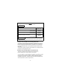
1
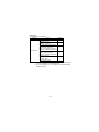
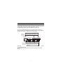
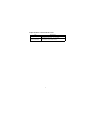
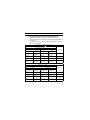
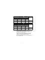
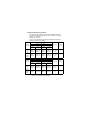
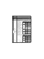
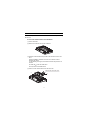
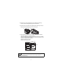
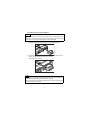
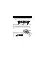
MODEL GT15-J61BT13 CC-Link communication unit User's Manual Thank you for purchasing the GOT1000 Series. Prior to use, please read both this manual and detailed manual thoroughly to fully understand the product. MODEL GT15-J61BT13-U MODEL CODE 1D7M57 IB(NA)-0800351-G(1410)MEE SAFETY PRECAUTIONS (Always read these instructions before using this equipment.) Before using this product, please read this manual and the relevant manuals introduced in this manual carefully and pay full attention to safety to handle the product correctly. The instructions given in this manual are concerned with this product. In this manual, the safety instructions are ranked as "WARNING" and "CAUTION". WARNING Indicates that incorrect handling may cause hazardous conditions, resulting in death or severe injury. CAUTION Indicates that incorrect handling may cause hazardous conditions, resulting in medium or slight personal injury or physical damage. Note that the CAUTION level may lead to a serious accident according to the circumstances. Always follow the precautions of both levels because they are important to personal safety. Please save this manual to make it accessible when required and always forward it to the end user. A-1 [DESIGN PRECAUTIONS] WARNING Some faults of this unit may keep the outputs on or off. An external monitoring circuit should therefore be provided to check for output signals which may lead to a serious accident. Not doing so can cause an accident due to mis-output or misoperation. If a communication error (including cable disconnection) occurs during monitoring with the GOT, communication between the GOT and master station is interrupted, disabling operation. When using the GOT to configure a system, assume that a GOT communication error will occur and configure a system in which switches used to perform significant operation for the system are provided on any device other than the GOT. Not doing so can cause an accident due to mis-output or misoperation. CAUTION Do not bunch the control wires or communication cables with the main circuit or power wires, or lay them close to each other. As a guide, separate the lines by a distance of at least 100mm (3.94 inches) otherwise malfunctions may occur due to noise. [INSTALLATION PRECAUTIONS] WARNING Be sure to shut off all phases of the external power supply used by the system before mounting or removing this unit to/from the GOT. Not doing so can cause a unit failure or misoperation. A-2 [INSTALLATION PRECAUTIONS] CAUTION Use this unit in the environment that satisfies the general specifications described in the User's Manual for the GOT used. Not doing so can cause an electric shock, fire, malfunction or product damage or deterioration. When installing this unit to the GOT, fit it to the connection interface of the GOT and tighten the mounting screws in the specified torque range (0.36 N•m to 0.48 N•m) with a Phillips-head screwdriver No.2. Undertightening can cause a drop, failure or malfunction. Overtightening can cause a drop, failure or malfunction due to screw or unit damage. [WIRING PRECAUTIONS] WARNING Be sure to shut off all phases of the external power supply used by the system before wiring. Not doing so can cause an electric shock, product damage or misoperation. CAUTION Connect the connectors to the unit securely. Always ground the FG terminal of the GOT power supply and the FG termial of this unit to the protective ground conducter. Be sure to ground the GOT and this unit separately. Not doing so may cause an electric shock or misoperation. Before wiring the unit, confirm the rated voltage and terminal arrangement of the product. A fire or failure can occur if the power supply connected is different from the rating or wiring is incorrect. Use applicable solderless terminals and tighten them with the specified torque. If any solderless spade terminal is used, it may be disconnected when the terminal screw comes loose, resulting in failure. A-3 [WIRING PRECAUTIONS] CAUTION Tighten the terminal screws within the specified torque range. Undertightening can cause a short circuit or misoperation. Overtightening can cause a short circuit or misoperation due to damaged screws or unit. Ensure that foreign matters such as chips and wire off-cuts do not enter the unit. They can cause a fire, failure or misoperation. Be sure to fix the wires or cables by ducts or clamps when connecting them to the unit. Not doing so can damage the unit or cables due to dangling, moved or accidentally pulled cables or can cause misoperation due to cable contact fault. Do not install the control lines together with the communication cables, or bring them close to each other. Failure to do so may cause malfunctions due to noise. When disconnecting a communication or power supply cable from the unit, do not pull on the cable itself. Disconnect cables fitted with connectors by holding and pulling the cable connector. Disconnect cables not fitted with a connector by removing the screws from the part connected to the unit. Pulling on a cable that is connected to the unit can cause damage to the unit or cable, or malfunction due to cable connection faults. [TEST OPERATION PRECAUTIONS] WARNING Do not output (switch on) any reserved signal among the output signals provided from the master unit to the GOT. Doing so can cause the PLC system to misoperate. A-4 [STARTUP AND MAINTENANCE PRECAUTIONS] WARNING Do not touch the terminals while power is on. Doing so can cause an electric shock or misoperation. Before starting cleaning or terminal screw retightening, always switch power off externally in all phases. Not doing so can cause a unit failure or misoperation. Undertightening can cause a drop, short circuit or misoperation. Overtightening can cause a drop, short circuit or misoperation due to damaged screws or unit. CAUTION Do not disassemble or modify the unit. Doing so can cause a failure, misoperation, injury or fire. Do not touch the conductive areas and electronic parts of the unit. Doing so can cause the unit to misoperate or fail. Do not drop the unit or subject it to strong impact. Doing so can damage the unit. Always make sure to touch the grounded metal to discharge the electricity charged in the body, etc., before touching the unit. Failure to do so may cause a failure or malfunctions of the unit. [DISPOSAL PRECAUTIONS] CAUTION Dispose of this product as industrial waste. A-5 [TRANSPORTATION PRECAUTIONS] CAUTION Make sure to transport the GOT main unit and/or relevant unit(s) in the manner they will not be exposed to the impact exceeding the impact resistance described in the general specifications of Use this unit in the environment that satisfies the general specifications described in the User's Manual for the GOT used., as they are precision devices. Failure to do so may cause the unit to fail. Check if the unit operates correctly after transportation. When fumigants that contain halogen materials such as fluorine, chlorine, bromine, and iodine are used for disinfecting and protecting wooden packaging from insects, they cause malfunction when entering our products.Please take necessary precautions to ensure that remaining materials from fumigant do not enter our products, or treat packaging with methods other than fumigation (heat method).Additionally, disinfect and protect wood from insects before packing products. A-6 REVISIONS * The manual number is noted at the lower right of the top cover. Print Date *Manual Number Revision Mar., 2006 IB(NA)-0800351-A First edition Sep., 2006 IB(NA)-0800351-B Partial additon Chapter 1 Addition Compliance with the EMC and Low Voltage Directives Jul., 2007 IB(NA)-080351-C Jan., 2009 IB(NA)-0800351-D Partial addition Chapter 1, 2, 4, 5 Jun., 2009 IB(NA)-0800351-E Partial corrections Compliance with the EMC and Low Voltage Directives Jun., 2011 IB(NA)-0800351-F Partial corrections Chapter 4 Partial addition Compliance with the Radio Waves Act (South Korea) Oct., 2014 IB(NA)-080351-G Partial corrections Compliance with the EMC and Low Voltage Directive,Chapter 2, 4, 5 Partial corrections SAFETY PRECAUTIONS Chapter 4, 5 This manual confers no industrial property rights or any rights of any other kind, nor does it confer any patent licenses. Mitsubishi Electric Corporation cannot be held responsible for any problems involving industrial property rights which may occur as a result of using the contents noted in this manual. © 2006 MITSUBISHI ELECTRIC CORPORATION A-7 CONTENTS 1. OVERVIEW .................................................................................................... 1 2. SPECIFICATIONS ......................................................................................... 2 2.1 Performance Specifications ..................................................................... 2 2.2 Specifications of terminal block socket .................................................... 4 3. I/O SIGNALS AND REMOTE REGISTER ASSIGNMENT ............................ 5 3.1 I/O Signals Transferred to/from the Master Module ................................ 5 3.2 Remote Register Assignment .................................................................. 7 4. PART NAMES AND EXTERNAL DIMENSIONS ........................................... 8 5. INSTALLATION PROCEDURE ................................................................... 11 5.1 CC-Link communication unit installation ................................................ 11 5.2 Terminal block socket installation .......................................................... 13 6. WIRING METHOD ....................................................................................... 14 A-8 Manuals The following shows manuals relevant to this product. Detailed Manual Manual number (Model code) Manual name GT16 User's Manual (Hardware) (Sold separately) SH-080928ENG (1D7MD3) (Sold separately) SH-080528ENG (1D7M23) GT15 User's Manual GOT1000 Series Connection Manual (Mitsubishi Products) for GT Works3 (Sold separately) SH-080868ENG (1D7MC2) Relevant Manuals For relevant manuals, refer to the PDF manuals stored in the DVD-ROM for the drawing software used. Compliance with the EMC and Low Voltage Directives To configure a system meeting the requirements of the EMC and Low Voltage Directives when incorporating the Mitsubishi GOT (EMC and Low Voltage Directives compliant) into other machinery or equipment, refer to "EMC AND LOW VOLTAGE DIRECTIVES" of the General Description included with the GOT used. The CE mark, indicating compliance with the EMC and Low Voltage Directives, is printed on the rating plate of the GOT. Compliance with the Radio Waves Act (South Korea) This product complies with the Radio Waves Act (South Korea). Note the following when using the product in South Korea. 이 기기는 업무용 (A 급 ) 전자파적합기기로서 판매자 또는 사용자는 이 점을 주의하시기 바라며 , 가정외의 지역에서 사용하는 것을 목적으 로 합니다 . (The product is for business use (Class A) and meets the electromagnetic compatibility requirements. The seller and the user must note the above point, and use the product in a place except for home.) A-9 Packing List The following items are included. Model Product GT15-J61BT13 Quantity CC-Link communication unit 1 Mounting screw set (2 screws, 2 stickers) 2 Extension interface relay board 1 Terminating resistor 110 1/2W (brown, brown, brown)*1 Plate type solderless terminal set 1 Terminating resistor 130 1/2W (brown, orange, brown)*2 Plate type solderless terminal set 1 Solderless terrninal (For connecting the braid shield wire, Plate type) 2 Terminal block socket 1 *1 Use it when using the Ver.1.10 compatible CC-Link dedicated cable/ Ver.1.00 compatible CC-Link dedicated cable. *2 Use it when using the Ver.1.00 compatible CC-Link dedicated highperformance cable. A-10 1. OVERVIEW This user’s manual introduces the model GT15-J61BT13 CC-Link communication unit (hereinafter referred to as CC-Link communication unit) used in the Control & Communication Link system (hereinafter referred to as CC-Link). For attachable GOTs, refer to the User's Manual for the GOT used. The CC-Link communication unit can be connected to the GOT, which can perform monitoring as an intelligent device station (number of occupied stations selectable from 1 station / 4 stations) in the CC-Link system. The PLC CPU on the Master/local station of Monitoring by the CC-Link system can be monitored. Transient Transmission Intelligent device station Remote device Local station Master station station CC-Link dedicated cable Monitoring by Cyclic Transmission All remote inputs/outputs and remote registers assigned to the Master station by CC-Link parameter setting can be monitored. When using the CC-Link connection, make the communication setting to perform communication with PLCs. For the details of CC-Link connection, refer to GOT1000 Series Connection Manual. 1 2. SPECIFICATIONS 2.1 Performance Specifications The following is the performance specification of CC-Link communication unit. The general specification of the CC-Link communication unit are the same as those of the GOT. For the general specifications of the GOT refer to the User's Manual for the GOT used. *1 Item Specifications CC-Link station type Intelligent device station Number of occupied stations Ver.2 mode Maximum number of link points per system Ver.1 mode May be selected between 1 and 4. Remote I/O(RX, RY)*2 8192 points Remote register(RWw) 2048 points Remote register(RWr) 2048 points Remote I/O(RX, RY)*2 2048 points Remote register(RWw) 256 points Remote register(RWr) 256 points Number of link points per station Refer to *3 Number of link points per number of occupied stations Refer to *4 Transmission speed Max. transmission distance 156kbps/625kbps/2.5Mbps/5Mbps/10Mbps Depends on the transmission speed. 26 The max. number of modules connected depends on the configuration of the CC-Link system to be used. Max. number of modules connected For more details on the max. number of modules connected, refer to the CC-Link System Master-Local Module User’s Manual. Connection cable CC-Link dedicated cable Internal current consumption (5VDC) 0.56A Weight 0.18kg (0.40Ib) *1 When installing an extension unit on the CC-Link communication unit, limit the maximum operating ambient temperature by subtracting 5 degrees from operating ambient temperature of the general specifications. *2 Each of the I/O signals (RX, RY) occupies 16 points of a system area within device points. For more details on the I/O signals, refer to Section 3.1. 2 *3 The number of link points per station depends on the mode setting of CC-Link as shown below. For CC-Link Ver.2 Number of link points per station Link device Extension cyclic setting Single Double Quadruple Octuple Remote I/O(RX, RY) 32 points 32 points 64 points 128 points Remote register(RWw) 4 points 8 points 16 points 32 points Remote register(RWr) 4 points 8 points 16 points 32 points For CC-Link Ver.1 Link device Number of link points per station Remote I/O(RX, RY) 32 points Remote register(RWw) 4 points Remote register(RWr) 4 points *4 The number of link points per number of occupied stations depends on the mode setting of CC-Link as shown below. For CC-Link Ver.2 Number of link points per station Extension cyclic setting Link device Single Double Quadruple Octuple 1 4 1 4 1 4 1 4 station station station station station station station station occup- occup- occup- occup- occup- occup- occup- occupied ied ied ied ied ied ied ied Remote I/O(RX, RY) 32 points 128 points 32 points 224 points 64 points 448 points 128 points 896 points Remote register(RWw) 4 points 16 points 8 points 32 points 16 points 64 points 32 points 128 points Remote register(RWr) 4 points 16 points 8 points 32 points 16 points 64 points 32 points 128 points For CC-Link Ver.1 Link device Number of link points per station 1 station occupied 4 station occupied Remote I/O(RX, RY) 32 points 128 points Remote register(RWw) 4 points 16 points Remote register(RWr) 4 points 16 points 3 2.2 Specifications of terminal block socket Item Specifications Screw tightening torgue Wiring screw Terminal block fixing screw Recommended driver Flat-blade screwdriver (Blade thickness 0.6mm, Width 3.5mm) 4 : 0.5 to 0.6 N•m : 0.7 to 0.8 N•m 3. I/O SIGNALS AND REMOTE REGISTER ASSIGNMENT 3.1 I/O Signals Transferred to/from the Master Module The following table lists the I/O signals assigned to the GOT. The I/O signals differ according to the set number of occupied stations (1 or 4 stations). n in the table indicates the address assigned to the Master module by station number setting. Signal Direction : GOT Master module Device No. Extension cyclic setting*1 Single 1 station occupied Signal name Double 4 station occupied 1 station occupied 4 station occupied RXn0 to RXnF RXn0 to RX(n+6)F RXn0 to RXnF RXn0 to RX(n+C)F RX(n+1)0 to RX(n+1)A RX(n+7)0 to RX(n+7)A RX(n+1)0 to RX(n+1)A RX(n+D)0 to RX(n+D)A RX(n+1)B RX(n+7)B RX(n+1)B RX(n+D)B RX(n+1)C to RX(n+1)F RX(n+7)C to RX(n+7)F RX(n+1)C to RX(n+1)F RX(n+D)C to RX(n+D)F Signal Direction : GOT User area Reserved Remote READY flag*2 Reserved Master module Device No. Extension cyclic setting*1 Quadruple 1 station occupied 4 station occupied Signal name Octuple 1 station occupied 4 station occupied RXn0 to RX(n+2)F RXn0 to RX(n+1A)F RXn0 to RX(n+6)F RXn0 to RX(n+36)F RX(n+3)0 to RX(n+3)A RX(n+1B)0 to RX(n+1B)A RX(n+7)0 to RX(n+7)A RX(n+37)0 to RX(n+37)A RX(n+3)B RX(n+1B)B RX(n+7)B RX(n+37)B RX(n+3)C to RX(n+3)F RX(n+1B)C to RX(n+1B)F RX(n+7)C to RX(n+7)F RX(n+37)C to RX(n+37)F 5 User area Reserved Remote READY flag*2 Reserved Signal Direction : GOT Master module Device No. Extension cyclic setting*1 Single 1 station occupied Signal name Double 4 station occupied 1 station occupied 4 station occupied RYn0 to RYnF RYn0 to RY(n+6)F RYn0 to RYnF RYn0 to RY(n+C)F User area RY(n+1)0 to RY(n+1)F RY(n+7)0 to RY(n+7)F RY(n+1)0 to RY(n+1)F RY(n+D)0 to RY(n+D)F Reserved Signal Direction : GOT Master module Device No. Extension cyclic setting*1 Quadruple 1 station occupied 4 station occupied Signal name Octuple 1 station occupied 4 station occupied RYn0 to RY(n+2)F RYn0 to RY(n+1A)F RYn0 to RY(n+6)F RYn0 to RY(n+36)F User area RY(n+3)0 to RY(n+3)F RY(n+1B)0 to RY(n+1B)F RY(n+7)0 to RY(n+7)F RY(n+37)0 to RY(n+37)F Reserved *1 When the mode setting of CC-Link is Ver.1, the extension cyclic setting is not available. (Fixed to Single) *2 The remote READY flag is on during startup of the GOT. It switches on when GOT power is switched on, hardware reset is made, or the GOT is ready to operate. If GOT power is on, the remote READY flag is off when offline operation is performed (during OS installation or screen data downloading) or while initial processing is executed. Use it for the interlock ladder when writing or reading data to or from the CC-Link Master station. 6 3.2 Remote Register Assignment The following is the assignment of the remote registers of the GOT. The remote registers differ according to the set number of occupied stations (1 or 4 stations). All areas are use areas. m and n in the table indicate the addresses assigned to the Master module by station number setting. Address Transfer Direction Master station Extension cyclic setting*3 Single Double Description Default Value 1 station occupied 4 station occupied 1 station occupied 4 station occupied RWwm to RWwm+3 RWwm to RWwm+F RWwm to RWwm+7 RWwm to RWwm+1F User wirte area 0 RWrn to RWrn+3 RWrn to RWrn+F RWrn to RWrn+7 RWrn to RWrn+1F User read area 0 Description Default Value GOT GOT Master station Address Transfer Direction Master station Extension cyclic setting*3 Quadruple Octuple 1 station occupied 4 station occupied 1 station occupied 4 station occupied RWwm to RWwm+F RWwm to RWwm+3F RWwm to RWwm+1F RWwm to RWwm+7F User wirte area 0 RWrn to RWrn+F RWrn to RWrn+3F RWrn to RWrn+1F RWrn to RWrn+7F User read area 0 GOT GOT Master station *3 When the mode setting of CC-Link is Ver.1, the extension cyclic setting is not available. (Fixed to Single) 7 4. PART NAMES AND EXTERNAL DIMENSIONS GT15-J61BT13 133(5.24) 3 (0.12) 4) GOT 3) 2) 108(4.25) 98(3.86) 5) 4) 20 (0.79) 2.5 (0.10) 1) X 7) 8) 11 (0.43) 30.5(1.20) 21.5(0.85) 3(0.12) 6) 31.5(1.24) Dimensions of X when the CC-Link communication unit is mounted to the GOT. GOT GT16 GT15 GT27 19.5(0.77) 21(0.83) 23(0.91) - 12.1” 18(0.71) 18(0.71) 23(0.91) 23(0.91) 10.4” 21(0.83) 21(0.83) 23(0.91) 23(0.91) 8.4” 23(0.91) 23(0.91) 23(0.91) 23(0.91) 5.7” 23(0.91) 23(0.91) - 15” GT25 Unit:mm(inch) No. 1) 2) 3) 4) Name CC-Link communication connector Interface connector Extension connector Mounting screw Description Connector for connecting the CC-Link dedicated cable Extension connector installed to a front extension unit or the GOT Extension connector to which a back extension unit is installed Mounting screws fixed with a front extension unit or the GOT 8 No. 5) 6) 7) 8) Name Board fixing screw Rating plate Terminal block socket Description Screw for fixing the extension interface relay board Socket for connecting the CC-Link dedicated cable to the CC-Link communication connector This indicates the status of the CC-Link communication unit and the communication status. The LED lighting status includes the normal mode and error mode. (1) Normal mode LED name Status Details If any communication error occurs in the The GOT is being OFF reset. normal mode, specify the RUN error cause by the The unit is in a ON [NETWK unit status normal status. display] screen. The unit is in a OFF Refer to the User's normal status. Manual for the GOT used The communication for details on the ON statues of all stations [NETWK unit status are abnormal. ERR. display] screen. A communication (2) Error mode error has occurred at When the RUN LED is Flicker a station or a station flickering, the LED number is duplicated. indication will change to the error mode. Operation Data have not been If an error occurs in the OFF transmitted or the indicator LED GOT is being reset. error mode, restart the SD GOT. Data are being ON SD RUN If the error mode is not transmitted. released after restarting Data have not been RD ERR. the GOT, the system OFF received or the GOT alarm "460 is being reset. RD Communication unit Data are being ON error" may have received. occurred. For system alarms, refer to the User's Manual for LED name Status Details the GOT used. Flicker RUN No errors OFF A starting error has not occurred. ON A starting error has occurred. OFF A hardware failure has not occurred. ON A hardware failure has occurred. ERR. RD 9 The error mode has been entered. ON OFF 24(0.94) Extension interface relay board 27.5(1.08) 64(2.52) Unit:mm(inch) 10 5. INSTALLATION PROCEDURE The installation procedure for the CC-Link communication unit is explained using the GT1575. 5.1 CC-Link communication unit installation (1) Power off the GOT. (2) Remove two extension unit covers of the GOT. (3) Attach the extend interface relay board to the extend I/F-2 side on the GOT. After the installation, detach the connector cover from the extend interface relay board. For the following GOT types, the extension interface relay board is not needed. •GT1655,155 of the GOT1000 series •GT27,GT25 of the GOT2000 series (4) Fit the CC-Link communication unit in the GOT case. Remove the connector cover 4) 3) 11 (5) Fasten the CC-Link communication unit by tightening its mounting screws (4 places) with tightening torgue 0.36 to 0.48 N•m. (6) Fasten the bus connection unit by tightening the board fixing screws (2 places) with the tightening torque of 0.36 to 0.48 N•m. 5) 6) (7) When installing an extension unit on the unit that has been installed, remove the connector cover and the sticker. When not installing an extension unit on the unit that has been installed, in order to avoid receiving electrostatic, stick accessory stickers to cover the top of mounting screws (4 places). Keep the connector cover fixed. Keep the sticker stuck as it is. Connector cover Accessory sticker Sticker Accessory sticker POINT Remove the screws that fixes the extension interface relay board before removing the unit.(Above 6)) 12 5.2 Terminal block socket installation CAUTION Be sure to fix the wires or cables by ducts or clamps when connecting them to the unit. Not doing so can damage the unit or cables due to dangling, moved or accidentally pulled cables or can cause misoperation due to cable contact fault. (1) Insert the terminal block socket in the CC-Link communication unit. A (2) Fasten the terminal block by tightening the terminal block fixing screws (2 places) with the tightening torque of 0.7 to 0.8 N•m. (Expanded figure of part A) A terminal block fixing screw POINT When attaching or removing a communication cable to/from the terminal block socket, detach the terminal block socket from the connector. (When extension units are installed in multiple layers, the units do not have to be removed from the GOT main unit.) 13 6. WIRING METHOD The following diagram shows how to wire the GOT and CC-Link system modules. (1) Wiring the GOT and CC-Link system modules by CC-Link dedicated cable Master module GOT (Blue) DA (Yellow) DB (White) Terminal DG resistor SLD FG CC-Link dedicated cable DA DB DG SLD FG I/O module, etc. CC-Link dedicated cable DA DB Terminal DG resistor SLD FG When connecting the CC-Link dedicated cables of the previous station and next station, strip the wire sheaths off for 10mm (0.39 inch) and insert the cables into the terminal block socket with every two wires in the same color together. When connecting the braid shields of the CC-Link dedicated cables of the previous station and the next station, caulk each braid shield to the supplied solderless terminal (Plate type), then insert the shields into the terminal block socket. DG DB FG SLD Braid shield Ne xt n tio ta ss iou n 14 sta tio ev Braid shield 10mm (0.39inch) Pr Solderless terminal (Plate type) DA (2) When connecting the terminating resistor and FG cable When connecting the terminating resistors to the GOT, be sure to connect the terminating resistors (with the supplied plate type solderless terminal) at the position as shown below. When connecting the FG cable, strip the wire sheath of the FG cable (2mm2) off for 10mm (0.39 inch) and insert it into the terminal block socket. DG DB FG SLD Terminating resistor (with plate type solderless terminal) DA Power supply cable Conductor plate 10mm (0.39inch) Braid shield POINT • Tighten the terminal block wiring screws with the tightening torque of 0.5 to 0.6 N•m. • Tighten terminal block mounting screws with the tightening torque of 0.7 to 0.8 N•m. • The terminating resistors supplied with the master module or the CC-Link communication unit must be connected to the PLC module or GOT at both ends of the data link. (Connect them across DA-DB.) • Connect the shield wire of the CC-Link dedicated cable to SLD of each module. Since SLD is connected to FG internally, always ground the FG terminal and FG1 terminal to the protective ground conductor. • The FG terminal of the GOT power supply and the FG terminal of the CC-Link Communication unit must be connected separately. • When using the plate type solderless terminal, be sure to insert the terminal in the horizontal direction toward the terminal block. The solderless terminal may come off when it is inserted in the vertical direction. 15 MEMO 16 Warranty Mitsubishi will not be held liable for damage caused by factors found not to be the cause of Mitsubishi; machine damage or lost profits caused by faults in the Mitsubishi products; damage, secondary damage, accident compensation caused by special factors unpredictable by Mitsubishi; damages to products other than Mitsubishi products; and to other duties. For safe use • This product has been manufactured as a general-purpose part for general industries, and has not been designed or manufactured to be incorporated in a device or system used in purposes related to human life. • Before using the product for special purposes such as nuclear power, electric power, aerospace, medicine or passenger movement vehicles, consult with Mitsubishi. • This product has been manufactured under strict quality control. However, when installing the product where major accidents or losses could occur if the product fails, install appropriate backup or failsafe functions in the system. Country/Region Sales office/Tel U.S.A Mitsubishi Electric Automation Inc. 500 Corporate Woods Parkway Vernon Hills, IL 60061, U.S.A. Tel : +1-847-478-2100 Brazil MELCO-TEC Rep. Com.e Assessoria Tecnica Ltda. Rua Correia Dias, 184, Edificio Paraiso Trade Center-8 andar Paraiso, Sao Paulo, SP Brazil Tel : +55-11-5908-8331 Germany Mitsubishi Electric Europe B.V. German Branch Gothaer Strasse 8 D-40880 Ratingen, GERMANY Tel : +49-2102-486-0 U.K Mitsubishi Electric Europe B.V. UK Branch Travellers Lane, Hatfield, Hertfordshire., AL10 8XB, U.K. Tel : +44-1707-276100 Italy Mitsubishi Electric Europe B.V. Italian Branch Centro Dir. Colleoni, Pal. Perseo-Ingr.2 Via Paracelso 12, I-20041 Agrate Brianza., Milano, Italy Tel : +39-039-60531 Spain Mitsubishi Electric Europe B.V. Spanish Branch Carretera de Rubi 76-80, E-08190 Sant Cugat del Valles, Barcelona, Spain Tel : +34-93-565-3131 France Mitsubishi Electric Europe B.V. French Branch 25, Boulevard des Bouvets, F-92741 Nanterre Cedex, France Tel : +33-1-5568-5568 South Africa Circuit Breaker Industries Ltd. Private Bag 2016, ZA-1600 Isando, South Africa Tel : +27-11-928-2000 Country/Region Sales office/Tel Hong Kong Mitsubishi Electric Automation (Hong Kong) Ltd. 10th Floor, Manulife Tower, 169 Electric Road, North Point, Hong Kong Tel : +852-2887-8870 China Mitsubishi Electric Automation (China) Ltd. 4/F Zhi Fu Plazz, No.80 Xin Chang Road, Shanghai 200003, China Tel : +86-21-6120-0808 Taiwan Setsuyo Enterprise Co., Ltd. 6F No.105 Wu-Kung 3rd.Rd, Wu-Ku Hsiang, Taipei Hsine, Taiwan Tel : +886-2-2299-2499 Mitsubishi Electric Automation Korea Co., Ltd. Korea 1480-6, Gayang-dong, Gangseo-ku Seoul 157-200, Korea Tel : +82-2-3660-9552 Singapore Mitsubishi Electric Asia Pte, Ltd. 307 Alexandra Road #05-01/02, Mitsubishi Electric Building, Singapore 159943 Tel : +65-6470-2460 Thailand Mitsubishi Electric Automation (Thailand) Co., Ltd. Bang-Chan Industrial Estate No.111 Moo 4, Serithai Rd, T.Kannayao, A.Kannayao, Bangkok 10230 Thailand Tel : +66-2-517-1326 Indonesia P.T. Autoteknindo Sumber Makmur Muara Karang Selatan, Block A/Utara No.1 Kav. No.11 Kawasan Industri Pergudangan Jakarta - Utara 14440, P.O.Box 5045 Jakarta, 11050 Indonesia Tel : +62-21-6630833 India Messung Systems Pvt, Ltd. Electronic Sadan NO:III Unit No15, M.I.D.C Bhosari, Pune-411026, India Tel : +91-20-2712-3130 Australia Mitsubishi Electric Australia Pty. Ltd. 348 Victoria Road, Rydalmere, N.S.W 2116, Australia Tel : +61-2-9684-7777 HEAD OFFICE : TOKYO BUILDING, 2-7-3 MARUNOUCHI, CHIYODA-KU, TOKYO 100-8310, JAPAN NAGOYA WORKS : 1-14, YADA-MINAMI 5-CHOME, HIGASHI-KU, NAGOYA, JAPAN When exported from Japan, this manual does not require application to the Ministry of Economy, Trade and Industry for service transaction permission. Specifications subject to change without notice. Printed in Japan, October 2014.