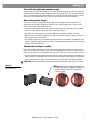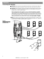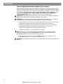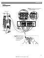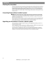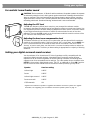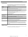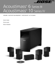
1
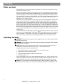
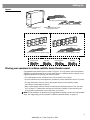
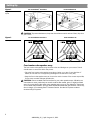
The Bose® Acoustimass® 15 Series II and Acoustimass 16
Home Entertainment Speaker Systems
August 13 , 2002
AM264924_00_V.pdf
Bose Corporation
Safety Information
WARNING: To reduce the risk of fire or electric shock, do not expose the powered
Acoustimass® module to rain or moisture.
CAUTION: To prevent electric shock, match wide blade of plug to wide slot, insert fully.
CA UTION
AVIS
RISK OF ELECTRICAL SHOCK
DO NOT OPEN
RISQUE DE CHOC ÉLECTRIQUE
NE PAS OUVRIR
CAUTION: TO REDUCE THE RISK OF ELECTRIC SHOCK,
DO NOT REMOVE COVER (OR BACK).
NO USER-SERVICABLE PARTS INSIDE.
REFER SERVICING TO QUALIFIED PERSONNEL.
ATTENTION : AFIN DE RÉDUIRE LE RISQUE DE CHOC ÉLECTRIQUE,
NE PAS RETIRER LE CAPOT DE L’APPAREIL (ou son panneau arrière).
IL N’EXISTE À L’INTERIEUR DE CET ÉQUIPEMENT AUCUN ÉLÉMENT
OU SOUS-ENSEMBLE POUVANT ÊTRE DEPANNÉ PAR L’UTILISATEUR.
LA MAINTENANCE DOIT ÊTRE RÉALISÉE PAR UN PERSONNEL QUALIFIÉ.
These CAUTION marks may be located on the Acoustimass module:
The lightning flash with arrowhead symbol, within an equilateral triangle, is intended
to alert the user to the presence of uninsulated dangerous voltage within the system
enclosure that may be of sufficient magnitude to constitute a risk of electric shock.
The exclamation point within an equilateral triangle, as marked on the system, is
intended to alert the user to the presence of important operating and maintenance
instructions in this owner’s guide.
Additional safety information
See the additional safety information on the Important Safety Instructions page enclosed with
your speaker system.
Please read this owner’s guide
Please take the time to follow this owner’s guide carefully. It will help you set up and operate
your system properly, and enjoy all of its advanced features. Please save your owner’s guide
for future reference.
CAUTION: No naked flame sources, such as lighted candles, should be placed on the
apparatus.
For your records
The system serial number is located on the bottom of the Acoustimass module.
Serial number: ________________________________________________________
Dealer name: _________________________________________________________
Dealer phone: ____________________ Purchase date ____________________
Please keep your sales receipt and warranty card together with this owner’s guide.
©2002 Bose Corporation. No part of this work may be reproduced, modified, distributed or otherwise used without
prior written permission.
Manufactured under license from Dolby Laboratories. “Dolby” and the double-D symbol are trademarks of Dolby
Laboratories. Confidential Unpublished Works. ©1992-1997 Dolby Laboratories. All rights reserved.
2
AM264924_00 _V.pdf • August 13, 2002
Contents
Where to find…
Setting Up . . . . . . . . . . . . . . . . . . . . . . . . . . . . . . . . . . . . . . . . . . . . . . . . . . . . . . . . . . . . . . . . . . . . .
Before you begin . . . . . . . . . . . . . . . . . . . . . . . . . . . . . . . . . . . . . . . . . . . . . . . . . . . . . . . . . . . .
Unpacking the carton . . . . . . . . . . . . . . . . . . . . . . . . . . . . . . . . . . . . . . . . . . . . . . . . . . . . . . . . .
Placing your speakers to achieve realistic home theater sound . . . . . . . . . . . . . . . . . . . . . . . .
Front center cube speaker array . . . . . . . . . . . . . . . . . . . . . . . . . . . . . . . . . . . . . . . . . . . . .
Front left and right cube speaker arrays . . . . . . . . . . . . . . . . . . . . . . . . . . . . . . . . . . . . . . .
Rear cube speaker arrays . . . . . . . . . . . . . . . . . . . . . . . . . . . . . . . . . . . . . . . . . . . . . . . . . .
Powered Acoustimass® module . . . . . . . . . . . . . . . . . . . . . . . . . . . . . . . . . . . . . . . . . . . . . .
Connecting the speakers . . . . . . . . . . . . . . . . . . . . . . . . . . . . . . . . . . . . . . . . . . . . . . . . . . . . . .
Connecting front cube speaker arrays to the Acoustimass module . . . . . . . . . . . . . . . . . .
Connecting rear cube speaker arrays to the Acoustimass module . . . . . . . . . . . . . . . . . . .
Connecting the Acoustimass module to the receiver . . . . . . . . . . . . . . . . . . . . . . . . . . . . .
Checking the connections . . . . . . . . . . . . . . . . . . . . . . . . . . . . . . . . . . . . . . . . . . . . . . . . . . . . .
Connecting the Acoustimass module to power . . . . . . . . . . . . . . . . . . . . . . . . . . . . . . . . . . . . .
Upgrading your Acoustimass 15 Series II speaker system . . . . . . . . . . . . . . . . . . . . . . . . . . . .
4
4
4
5
6
7
7
7
8
8
9
10
12
12
12
Using your system . . . . . . . . . . . . . . . . . . . . . . . . . . . . . . . . . . . . . . . . . . . . . . . . . . . . . . . . . . . . . .
For realistic home theater sound . . . . . . . . . . . . . . . . . . . . . . . . . . . . . . . . . . . . . . . . . . . . . . . .
Adjusting the LFE level . . . . . . . . . . . . . . . . . . . . . . . . . . . . . . . . . . . . . . . . . . . . . . . . . . . .
Adjusting the bass/room compensation level . . . . . . . . . . . . . . . . . . . . . . . . . . . . . . . . . . .
Setting your digital surround sound receiver . . . . . . . . . . . . . . . . . . . . . . . . . . . . . . . . . . . . . . .
Be sure to get the digital audio signal . . . . . . . . . . . . . . . . . . . . . . . . . . . . . . . . . . . . . . . . . . . .
Setting your analog surround sound receiver . . . . . . . . . . . . . . . . . . . . . . . . . . . . . . . . . . . . . .
13
13
13
13
13
14
14
Reference . . . . . . . . . . . . . . . . . . . . . . . . . . . . . . . . . . . . . . . . . . . . . . . . . . . . . . . . . . . . . . . . . . . . .
Troubleshooting . . . . . . . . . . . . . . . . . . . . . . . . . . . . . . . . . . . . . . . . . . . . . . . . . . . . . . . . . . . . .
Customer service . . . . . . . . . . . . . . . . . . . . . . . . . . . . . . . . . . . . . . . . . . . . . . . . . . . . . . . . . . . .
Cleaning the speakers . . . . . . . . . . . . . . . . . . . . . . . . . . . . . . . . . . . . . . . . . . . . . . . . . . . . . . . .
Technical information . . . . . . . . . . . . . . . . . . . . . . . . . . . . . . . . . . . . . . . . . . . . . . . . . . . . . . . . .
Warranty period . . . . . . . . . . . . . . . . . . . . . . . . . . . . . . . . . . . . . . . . . . . . . . . . . . . . . . . . . . . . .
Accessories . . . . . . . . . . . . . . . . . . . . . . . . . . . . . . . . . . . . . . . . . . . . . . . . . . . . . . . . . . . . . . . .
15
15
15
16
16
17
17
3
AM264924_00 _V.pdf • August 13, 2002
Setting Up
Before you begin
We appreciate your choice of the Bose® Acoustimass® 15 series II or Acoustimass 16 home
entertainment speaker system.
Bose Virtually Invisible® speaker technology allows you to enjoy lifelike home performances
from the very latest surround-sound encoded movies, CDs, and television shows, without a
room full of speakers. The cube speaker arrays, along with the powered Acoustimass module, reproduce the full-spectrum of sound from multi-channel digital programming. Integrated
Signal Processing assures full bass performance from all channels at all listening levels,
regardless of your receiver settings.
Your stereo VCR, stereo television, or DVD player sends the encoded program material to the
surround-sound receiver, which interprets and distributes the information to the powered
Acoustimass module. The module delivers the bass for all channels and sends appropriate
sounds to each cube speaker array. The sound mix varies with different program types: dialogue is usually sent to the center cube speaker array, a visual soundstage is created by the
left and right front cube speaker arrays, and you feel as if you are in the center of the action
because sounds and special effects are directed to the rear cube speaker arrays. At any point
in a surround-sound performance, you may hear sound from one, a few, or all of the cube
speaker arrays.
To select surround-encoded program material, look for the terms Surround, Dolby Surround,
the double-D symbol 3, Dolby Digital 1, other digital formats, or the word “surround” preceding a TV broadcast. Your system is compatible with home theater receivers.
You can also enjoy a wide variety of stereo programming that is not surround-encoded.
Unpacking the carton
WARNING: The powered Acoustimass module weighs 33 pounds (15 kg). Use good lifting
practice to avoid injury.
WARNING: To avoid danger of suffocation, keep the plastic bags that wrap these speakers
out of the reach of children.
Note: This product is not to be powered by any DC-to-AC inverters that may be found in
automobiles, recreational vehicles, boats, ships, or other similar situations.
Carefully unpack the carton contents (Figure 1):
1.
Remove the brown inner carton containing the cube speaker arrays.
2.
Gently roll the carton over onto its side.
3.
Slowly pull the Acoustimass module from the carton.
4.
Stand the module up.
If the cube speaker arrays or the module appear damaged, do not use them. Repack everything in the original carton and contact your authorized Bose dealer immediately. Or, to contact Bose directly, see the list of offices and phone numbers enclosed with your system.
Note: Now is a good time to record the serial number of these speakers on page 2 of this
guide and on your warranty card. Please save all packing materials for possible future use.
4
AM264924_00 _V.pdf • August 13, 2002
Setting Up
Figure 1
Carton contents
20-ft (6.1m) system input cable
Three 20-ft (6.1m) front speaker cables
®
Powered Acoustimass
module
Rubber feet for front center
cube speaker array
With Acoustimass 15 Series II system
With Acoustimass 16 system
Six cube speaker arrays
Five cube speaker arrays
Two 50-ft (15.2m) rear speaker cables
Three 50-ft (15.2m) rear speaker cables
Power cord (1)
USA/Canada
Europe
UK/Singapore
Australia
Placing your speakers to achieve realistic home theater sound
A suggested home theater layout is shown in Figure 2. You may want to place the speakers
differently to take advantage of the sound characteristics of different rooms. Here are some
suggested guidelines for placing your speaker system:
• The cube speaker arrays are identical and can be used for any channel.
• All cube speaker arrays are magnetically shielded to prevent interference with a TV picture.
• The top and bottom sections of the cube speaker arrays can be rotated to create
room-filling sound patterns (Figure 3).
• Bose® wall brackets and floor stands can extend your placement options. See “Accessories” on page 17. Please follow wall bracket instructions carefully. Proper mounting will
ensure optimum performance and safety from your system.
Note: The Acoustimass 15 Series II may be upgraded by adding a center rear cube speaker
array. See “Upgrading your Acoustimass 15 Series II speaker system” on page 12.
5
AM264924_00 _V.pdf • August 13, 2002
Setting Up
Figure 2
For Acoustimass® 15 Series II
Suggested home theater
layouts
For Acoustimass 16
5'
6' - 1 )
m
5
(2
5'
6' - 1 )
m
5
(2
C
L
RR
R
LR
2'+ )
+
(0.6m
C
RR
R
CR
L
LR
2'+ )
+
(0.6m
CAUTION: To prevent interference, keep the Acoustimass module at least 2 feet (.6m) from
your TV set.
Figure 3
For Acoustimass 15 Series II
For Acoustimass 16
Sound patterns
Front center cube speaker array
The front center cube speaker array localizes action and dialogue on your screen. Sound
should seem to come from within the picture.
• Place the front center cube speaker array above, below, or on top of your television. If
below, be sure that it is not supporting the weight of the television in any way.
• Keep the front cube speaker array as close to the vertical center of the screen as possible,
for the most accurate dialogue reproduction.
CAUTION: Choose a stable and level surface for your cube speaker arrays. Vibration can
cause them to move, particularly on smooth surfaces like marble, glass, or highly polished
wood. If you are placing the center cube speaker array on top of your television, use the set
of four rubber feet provided. You may obtain additional rubber feet (part number 178321-04),
free of charge, by contacting Bose® Customer Service. See the list of phone numbers
included with your system.
6
AM264924_00 _V.pdf • August 13, 2002
Setting Up
Front left and right cube speaker arrays
The front left and right cube speaker arrays create a sound image wider than the screen that
seems natural to viewers sitting anywhere in the room. You can place the cube speaker arrays
near a TV screen with no picture interference. Place the front cube speaker arrays on either
side of your TV, at least 6 feet (2m), or as much as 15 feet (5m) apart (see Figure 2).
Rear cube speaker arrays
The rear, or surround cube speaker arrays add discrete sounds and special effects that
expand the visual image, bringing the viewer into the center of the action. The rear cube
speaker arrays may carry dialogue as well.
• Position the left and right rear cube speaker arrays to allow the sound to reach the viewer
from both sides, rather than from directly behind (see Figure 2).
• Place the rear cube speaker arrays at ear height (when seated) or higher, if possible.
• Rotate the top and bottom sections of the rear cube speaker arrays to direct the sound to
the front and back of the listener.
• If you have a center rear cube speaker array (Acoustimass 16 system or upgraded Acoustimass 15 Series II system), place it so that it is centered between the rear left and right cube
speaker arrays (see Figure 2).
Powered Acoustimass® module
Bose® Acoustimass speaker technology takes advantage of the fact that the source of pure
bass sound is difficult to locate, so you can hide the powered Acoustimass module conveniently out of sight. Place the module at the same end of the room as the television monitor.
• You may hide the module behind furniture, but do not block the opening. Be sure there is at
least 2 inches (5 cm) between any surface and the front opening or the grille on the bottom.
• If the opening faces the wall it increases the bass; if it faces away it decreases the bass.
CAUTION: To prevent interference, keep the module at least 2 feet (.6m) from your TV set.
Figure 4
Powered Acoustimass
module placement
Note: Placing the module horizontally, or on
its side, may reduce ventilation, inhibiting its
ability to play at full output for extended
periods of time.
7
AM264924_00 _V.pdf • August 13, 2002
Setting Up
Connecting the speakers
CAUTION: Never connect the cube speaker arrays directly to a receiver output. Always connect them to the powered Acoustimass® module, then connect the module to the receiver.
CAUTION: Never use broken or frayed wiring, which can result in electrical shock or damage
to your system. The supplied cables are not intended for in-wall installation. Check local
building codes or enlist a qualified installer.
Connecting front cube speaker arrays to the Acoustimass module
Three individual 20-foot (6.1m) speaker cables connect the center, right, and left front cube
speaker arrays to the Acoustimass module (Figure 5). Be sure to match the correct cable with
the corresponding speaker location. Front speaker cables have blue RCA connectors at one
end with L (left), R (right), or C (center) molded into the connectors. The other ends of the
cables have two wires. The red collars on the + wire are labeled LEFT, RIGHT, or CENTER.
Note: The center rear cube speaker array is included with the Acoustimass 16 system or may
be added to an Acoustimass 15 Series II system. For upgrading information, see “Upgrading
your Acoustimass 15 Series II speaker system” on page 12.
Figure 5
Left Center Right
Front Front Front
Audio Output
Left Center
Rear Rear
Right
Rear
Audio Input
Cube speaker array
connections to the
Acoustimass module
8
AM264924_00 _V.pdf • August 13, 2002
Setting Up
1.
Connect the wire pair marked CENTER to the center cube speaker array. Press the terminal tab on the back of the cube speaker array. Insert the marked (+) wire into the red terminal and the plain (–) wire into the black terminal. Release the tab to secure the wires.
2.
Connect the wire pair marked RIGHT to the right front cube speaker array (to the right of
the TV as you face it).
3.
Connect the wire pair marked LEFT to the left front cube speaker array.
4.
Plug the other end of each cable into the CENTER FRONT, RIGHT FRONT, and LEFT
FRONT blue RCA jacks, respectively, on the Acoustimass® module.
Connecting rear cube speaker arrays to the Acoustimass module
Each rear cube speaker array is connected to the Acoustimass module with a 50-foot (15m)
speaker cable (Figure 5). Be sure to match the correct cable with the corresponding speaker
location. Rear speaker cables have orange RCA connectors at one end with LR (left rear), RR
(right rear), or CR (center rear) molded into the connectors. The other ends of the cables have
two wires. The red collars on the + wires are labeled LEFT REAR, RIGHT REAR, or CENTER
REAR.
1.
Connect the wire pair marked RIGHT REAR to the right rear cube speaker array (on your
right as you face the TV). Press the terminal tab on the back of the cube speaker array.
Insert the marked wire into the red terminal and the plain wire into the black terminal.
Release the tab to secure the wires.
2.
Connect the wire pair marked LEFT REAR to the left rear cube speaker array.
3.
If you have a center rear cube speaker array (Acoustimass 16 system or upgraded Acoustimass 15 Series II system), connect the wire pair marked CENTER REAR to the center
rear cube speaker array.
Note: The Acoustimass 15 Series II system may be upgraded by adding a center rear cube
speaker array. See “Upgrading your Acoustimass 15 Series II speaker system” on page 12.
4.
Plug the other end of each cable into the RIGHT REAR, LEFT REAR, and CENTER
REAR orange RCA jacks, respectively, on the Acoustimass module.
9
AM264924_00 _V.pdf • August 13, 2002
Setting Up
Connecting the Acoustimass® module to the receiver
The 20-foot (6.1m) system input cable connects the module to your surround receiver (see
Figure 6). The system input cable has a multi-pin connector on one end and several wire pairs
on the other. The wire pairs of the cable may be separated or “unzipped” as much as needed
to comfortably reach the surround receiver connections. Each wire pair is marked on the
cable jacket with RIGHT, LEFT, CENTER, RIGHT SURROUND, LEFT SURROUND, or
CENTER SURROUND to indicate where each wire connects to the receiver.
CAUTION: Before making any connections turn off your receiver and unplug it from the AC
(mains) outlet. Not doing so may result in damage to your system.
CAUTION: Do not connect the powered Acoustimass module directly to your TV unless it
provides surround decoding circuitry and amplified outputs for all channels.
1.
Insert the multi-pin connector on the system input cable into the input jack on the Acoustimass module. Tighten the two thumbscrews to assure a secure connection.
2.
Connect each wire pair on the other end of the system input cable to your surround
receiver. Carefully match the polarity of the connections (+ to + and – to –).
• Attach each marked wire (+) to the appropriate + terminal.
• Attach each plain wire (–) to the appropriate – terminal.
Note: The RCA plug of the system input cable comes with a cover installed. Remove
this cover for connection to the LFE/SUBWOOFER OUT jack. If your receiver has no
LFE/SUBWOOFER OUT jack, leave the plug cover in place.
3.
If applicable, connect the RCA plug marked LFE on the system input cable to the
LFE/SUBWOOFER OUT jack on your surround receiver.
CAUTION: Do not allow exposed wires to brush against each other; this could damage your
receiver.
10
AM264924_00 _V.pdf • August 13, 2002
Setting Up
Figure 6
Acoustimass® module to
receiver connections
Note: The center surround connection
is used only when a center rear
speaker is installed.
FRONT SPEAKERS A
Thumbscrews
L
CENTER
R
L
CENTER
Left Center Right
Front Front Front
Center
Rear
Left
Rear
Audio Output
Right
Rear
Audio Input
R
FRONT SPEAKERS A
R
L
CENTER
SURROUND SPEAKERS
R
L
CENTER
LFE/SUBWOOFER
OUT
Note: Cables may be
separated or “unzipped”
as much as needed to
comfortably reach the
surround receiver
connections.
11
AM264924_00 _V.pdf • August 13, 2002
Setting Up
Checking the connections
Check all connections from the receiver to the Acoustimass® module and from the module to
the cube speaker arrays (Figure 5 and Figure 6). Make sure all cube speaker arrays are connected to the proper terminals according to their position in your room. Check that all wires
are connected to your surround receiver in phase (+ to + and – to –). Incorrect wiring can
result in a total loss of module output. Correct wiring problems before you plug your receiver
in and turn it on.
Connecting the Acoustimass module to power
Note: Bose® recommends using a quality surge suppressor on all electronics equipment.
Voltage variations and spikes can damage electronic components in any system. A quality
suppressor can eliminate the vast majority of failures attributed to surges and may be purchased at an electronics store.
After you have checked all system connections, plug the power cord of the powered Acoustimass module into an AC (mains) receptacle. Your Acoustimass speaker system will turn on
and off automatically as it receives a signal from your surround receiver.
Upgrading your Acoustimass 15 Series II speaker system
Your Acoustimass 15 Series II speaker system can be upgraded to provide you with 6.1 or
6 channel surround sound.
The 6.1 upgrade kit contains one black (PC 029661) or white (PC 029662) cube speaker array,
a 50-foot connecting cable, and complete connection instructions.
To purchase the 6.1 upgrade kit, contact your local authorized Bose retailer or call Bose
directly. See the list of Bose offices and phone numbers enclosed with your system. When
ordering, you will need to know the serial number of your Acoustimass module.
12
AM264924_00 _V.pdf • August 13, 2002
Using your system
For realistic home theater sound
CAUTION: The Acoustimass® 15 Series II and Acoustimass 16 speaker systems incorporate
an automatic protection circuit, which guards against most kinds of damage from electrical
stress or overload. This circuit activates at high volume levels to reduce output, causing a
slight decrease in volume. This is normal operation and indicates that power input may be
exceeding safe levels. Sustained listening at these levels is not recommended.
Adjusting the LFE level
The LFE (low-frequency effects) level control on your powered Acoustimass module
increases or decreases the relative level of low-frequency effects on movie sound tracks. Use
it to regulate the presence of these underlying deep bass sounds. Use the “test tones” feature
in your digital surround sound receiver to match the volume levels for each of the cube
speakers. Then use the LFE control on the Acoustimass module to match the volume of the
LFE channel to the cube speaker channels.
Adjusting the bass/room compensation level
This feature will allow you to fine-tune your system after you have placed the Acoustimass
module in your selected location. If the room sounds “thin” or lacks bass, turn the BASS control in a clockwise direction to increase the bass level of the module. If the room sounds
“boomy” or has too much bass, turn the knob in a counter-clockwise rotation to reduce the
bass level of the module. The factory or detent setting is appropriate for a majority of listening
situations.
Setting your digital surround sound receiver
Your Acoustimass 16 or Acoustimass 15 Series II speakers are fully compatible with the
output from digital surround receivers. Integrated Signal Processing assures full bass
reproduction for all channels regardless of receiver settings. However, the following table
suggests a set of recommended receiver settings. The cube speaker arrays should be set to
LARGE in the receiver’s digital display menu. The LFE, or subwoofer, is set to ON. If applicable, the crossover value should be set to the lowest number possible, typically 80 Hz.
Speaker
Receiver setting
Left and right
LARGE
Center
LARGE
Left and right surround
LARGE
Center surround*
LARGE
LFE/Subwoofer
ON
* Applies to Acoustimass 16 systems or upgraded Acoustimass 15 Series II systems. For upgrade
information, see “Upgrading your Acoustimass 15 Series II speaker system” on page 12.
13
AM264924_00 _V.pdf • August 13, 2002
Using your system
Be sure to get the digital audio signal
To be sure that the digital audio signal from your DVD player reaches your surround receiver,
connect the digital audio output from your DVD player to the digital audio input on your
receiver (Figure 7).
Before you play a DVD disc, be sure to select the digital output in the setup menu of your
DVD player. For additional setup and operating information, please refer to the owner’s guide
that came with your surround receiver.
Figure 7
Digital signal connections
on a surround receiver
Note: Use the optical or coaxial digital
input connections, but not both.
OR
DIGITAL PLAY IN
(OPTICAL)
IN
DIGITAL PLAY IN
IN
(OPTICAL)
PLAY IN
(COAXIAL)
PLAY IN
(COAXIAL)
FRONT SPEAKERS
R
L
SURROUND SPEAKERS
R REAR L CENTER
Setting your analog surround sound receiver
For analog surround sound (non-digital) applications, we recommend that you set the
surround-sound center mode of your receiver to WIDE. Instructions for this process vary,
depending on the brand and model of your surround receiver. Follow your receiver owner’s
guide for testing and adjusting the balance of each speaker.
14
AM264924_00 _V.pdf • August 13, 2002
Reference
Troubleshooting
If you have a problem with your Acoustimass® speaker system, turn off your sound source
and try the following solutions. If you still have a problem, contact your Bose® dealer to
arrange for service. To contact Bose directly, refer to the list of service offices and phone
numbers enclosed in the shipping carton.
Problem
What to do
System does not function
at all
• Make sure the receiver and powered Acoustimass module are plugged into an operating
AC wall outlet and that the receiver is turned on.
• Be sure to select a source at the receiver (video, CD, DVD, tuner).
No sound
• Check the speaker connections.
• Make sure that the powered Acoustimass module is plugged in.
• For digital sound, be sure a coaxial or optical cable connects the digital output of the
DVD player with the digital input on your receiver.
• Be sure the audio source selected is correct. For example, select DVD audio on your
receiver and player for DVD sound.
• Disconnect any headphones.
• Increase the volume.
No sound from cube
speaker arrays
• Be sure the powered Acoustimass module is plugged in and the receiver is turned on.
Sound is distorted
• Make sure speaker wire is not damaged.
• Reduce the volume of external components connected to the receiver.
No bass
• Be sure the speaker connections at the receiver/amplifier are correct (+ to + and – to –).
Not enough or too much
bass
• Move the powered Acoustimass module closer to a wall or corner to increase bass.
Move it farther away from a wall or corner to decrease bass.
• Adjust the LFE Level or Room Compensation control.
No surround sound
• Be sure your receiver is processing a signal from a Hi-Fi VCR, stereo TV, laserdisc, or
DVD player, or other surround-sound source.
• If you are using the Dolby Pro-Logic mode, check that surround-sound is turned on.
• If you are using digital programming, verify that the settings are correct at the receiver.
• Be sure the source material (DVD, laser disc, or broadcast programming) is Dolby Digital
encoded.
Customer service
For additional help in solving problems, contact Bose customer service. See the list of service
offices and phone numbers enclosed in the shipping carton.
15
AM264924_00 _V.pdf • August 13, 2002
Reference
Cleaning the speakers
The cabinets of your Acoustimass® speaker system may be cleaned only with a soft dry cloth.
Do not use any sprays near the system or allow liquids to spill into any openings. Also, do not
use any solvents, chemicals, or cleaning solutions containing alcohol, ammonia, or abrasives.
The grille assemblies on the cube arrays may be carefully vacuumed, if necessary. Please
note that the drivers are located directly behind the grille cloth, and are easily damaged if
reasonable care is not taken.
Technical information
Features
Direct/Reflecting® speaker technology
Virtually Invisible® speaker design
Acoustimass speaker technology combined with Integrated Signal Processing
Magnetically shielded cube speaker arrays
Automatic system protection circuitry
Syncom® computer quality control
Finish
Cube arrays: Black or Arctic White finish
Powered Acoustimass module: Scratch-resistant Black or Arctic White textured finish
Speaker driver complement
Cube speaker arrays: two 2.50-inch (6.35 cm) TwiddlerTM speakers
Powered Acoustimass module: Three 5.25-inch (13 cm) woofers
Speaker size/weight
Cube speaker arrays: 6.2"H x 3.1"W x 4.0"D (15.7 cm x 7.8 cm x 10.2 cm) / 2.4 lb (1.1 kg)
Acoustimass module: 16.3"H x 8.1"W x 29.1"D (41.4 cm x 20.6 cm x 73.9 cm) / 45 lb (20.3 kg)
Acoustimass 15 Series II
Acoustimass 16
Acoustimass
module power
rating
USA/Canada:
100-127V
50/60 Hz 400 W
USA/Canada:
100-127V
50/60 Hz 400 W
Europe/Australia:
220-240V
50/60 Hz 400 W
Europe/Australia:
220-240V
50/60 Hz 400 W
Connectivity
Compatible with A/V receivers and amplifiers rated from
10 to 200 watts per channel,
rated from 4 to 8 ohms
Compatible with A/V receivers and amplifiers rated from
10 to 200 watts per channel,
rated from 4 to 8 ohms
Packed system
weight
72.5 lb (32.6 kg)
75 lb (33.8 kg)
16
AM264924_00 _V.pdf • August 13, 2002
Reference
Warranty period
Your Bose® Acoustimass® speaker system is covered by a limited transferable warranty.
Details of the warranty are provided on the warranty card that came with your system. Please
fill out the information section on the card and mail it to Bose.
Accessories
• Table stands: UTS-20B (black), UTS-20W (white)
• Floor stands: UFS-20B (black), UFS-20W (white)
• Wall brackets: UB-20B (black), UB-20W (white)
• Module input cable adapter for use with existing wiring:
PN267138-001 (black)
PN267138-002 (white)
• Module-to-cube speaker array cable adapter for use with existing wiring:
PN267139-001 (black)
PN267139-002 (white)
• Module 20 ft (6.1m) input extension cable:
PN267140-001 (black)
PN267140-002 (white)
17
AM264924_00 _V.pdf • August 13, 2002
©2002 Bose Corporation, The Mountain,
Framingham, MA 01701-9168 USA
264924 AM Rev.00 JN20951
AM264924_00 _V.pdf • August 13, 2002