1
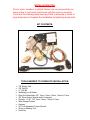
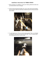
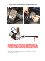
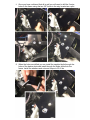
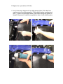
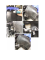
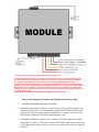
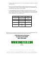
KIT NUMBER 8051510
YAMAHA RHINO Electric Steering Installation Manual
Thank you for purchasing our ELECTRA-STEER 12v electric assist
power steering system. Please carefully read this instruction sheet
entirely before you begin to install the system.
Remember before beginning installation, to insure that you are in a
well lit, organized work area. Engage the parking brake, disconnect
the battery until power is needed and chock or block the rear wheels
to insure the vehicle is stable.
Full refund will NOT be granted to any kits that are
damaged, scratched, or altered in any fashion.
INSTALLATION TIPS:
Due to minor variations in vehicle frames, we recommend that you
leave all the U-Joint pinch bolts loose until the motor is mounted.
Then rock the steering wheel back and forth to allow the U-Joints to
align themselves. Complete the installation by tightening these bolts.
KIT CONTENTS:
TOOLS NEEDED TO COMPLETE INSTALLATION:
•
•
•
•
•
•
•
•
•
•
•
•
3/8” Electric Drill
3/8” Drill Bit
½ “ Drill Bit
Soldering Iron & Solder
Open End Wrenches: 3/8”, 8mm, 10mm, 12mm, 13mm & 17mm
3/8” Drive Socket Wrench and 6” extension
Sockets: 15/16”, 3/8”, 8mm, 10mm, 13mm & 17mm
Wire Stripper/Cutters
Hammer
50 Ft Lb Adjustable Torque Wrench
Scribe or Marking Tool
Heat Gun
Installation Instructions for YAMAHA RHINO
1. Before starting your installation, center your steering wheel and make sure
your wheels are in line and straight.
2. Remove the pinch bolt that retains the u-joint to the steering shaft and the
rack and pinion. Slide the shaft down towards the pinion and remove shaft
from vehicle.
3. You will need to trim 1/8” of your stock steering shaft. Take a cut off wheel
or similar tool and trim off the very tip of the shaft. This is to ensure there
is no interference with the u-joint to shaft.
4. Remove the control module bolts from the frame and remove the module.
Note: The upper joint and lower shaft have been shipped attached and
are in phase. The shaft, u-joint, and motor are marked where the proper
location is. You do not need to remove the upper joint, but you will need
to remove the lower shaft for installation. Pay attention to the alignment
marks and make sure you install them back into the same place.
NOTE: PINK COLOR BANDS FACE VEHICLE SPLINES AND WHITE
FACE MOTOR SPLINES.
5. Your electric motor & module has come to you assembled. Install the
bracket, module, & motor assembly over the stock bolt holes in the frame
where the module was located. The upper joint needs to spline onto the
stock steering shaft as you align mount bracket. Once you have the joint in
place install the supplied pinch bolt through the joint and finger tighten.
6. Install the stock bolts from the module to hold the bracket in place. You
may have to leave out the bolt closest to the air box to allow pivot room to
spline lower shaft to the motor. After shaft is installed center and tighten
6mm bracket bolts.
7. Once bracket and motor is mounted, install the lower shaft and install the
pinch bolts in the u-joints and finger tighten. Verify that the assembly is not
binding. If it seems tight or binds you may need to loosen the 4 bolts on
the column tube and adjust the angle slightly. This is usually not
necessary.
8. Once you have confirmed that all is well you will need to drill the 2 extra
holes in the frame using the two 3/8” holes in the mtg. bracket as a pilot.
9. When the holes are drilled you can install the supplied bolts through the
holes of the backer plate and install through the holes drilled into the
frame. Install the washers and nuts and torque to 20 ft. lbs.
10. Remove the stock 6mm bolts installed in the mounting bracket. Install the
module back into its stock location and install the supplied 6mm longer
bolts through the module and bracket into frame & tighten to 15 ft. lbs.
11. Locate a spot on your dash and drill a ½ “ hole where you would like your
LED to be. Be sure to leave enough wire to get to the LED light.
12. Tighten the u-joint bolts to 20 ft.lbs.
13. Your kit has been shipped with a rubber splash shield. This shield sits
over the motor & module assembly. Fit the shield in place as shown and
drill ¼ “ holes in the perforated areas of the shield through the plastic on
firewall & framework. Install the supplied trim tabs to hold shield in place.
WIRING YOUR ELECTRA-STEER KIT:
1. The heavy red wire needs to go to a constant positive 12 volts. We
normally go to the battery but any constant source will work.
Note: The 30 amp slow blow fuse needs to be installed in line with this wire to
prevent damage or fire. *Failure to do so may result in a short circuit or
malfunction.
2. The heavy black wire needs to go to a constant ground. Again we prefer
the battery but a good and clean ground is fine.
*It is strongly suggested that all connections made be soldered & taped to
insure integrity. Shrink tube is also supplied to seal your connections.
3. The white wire gets a single spade connector put on it and is used for
diagnostic purposes, so it need to stay in an accessible spot.
4. The purple or brown wire gets a single spade connector put on it and is
used for diagnostic purposes and also needs to stay in an accessible spot.
Note: the White & Purple or Brown wires are used for trouble code reading and
clearing. They need to be located in an accessible place. They do not get
connected to anything.
5. The orange wire goes to one of the sides of the LED light.
6. The yellow and blue wire is not used for this application. It may be
trimmed back and taped into the harness.
7. The green wire is connected to a key on power source usually we use the
ignition switch lead. The other side of the LED also goes to this wire and
may be spliced in anywhere in this wire.
8. Be sure to leave the orange wire and the green wire long enough to go
through a hole in the dash where you want the light located.
9. Make sure your connections are good and your hardware is tightened to
spec and there is no binding in your steering linkage.
10. Install your steering wheel and torque to 35 ft. lbs. Make sure your wheels
are straight and that you install your steering wheel straight.
Yahama Rhino Supplement For Early Model Year
1. Remove original steering shaft after positioning front wheels straight forward. Cut
off the 1/8” bit from steering shaft assembly and proceed as follows
2. Place power steering unit on steering spline so four parallel holes in steering
bracket line up horizontally on frame cross member, temporarily securing it with
C clamps.
3. Install the new steering shaft to unit and to the Rhinos rack and pinion system.
Leave the pinch bolts finger tight.
4. Rotate steering wheel and watch rotation of steering shaft u-joints. Raise or lower
the mounting bracket until u-joints clear the brake light sensor and turns free of
any other obstacles.
5. Double check your shaft clearance and tighten C clamps in place in your final
position. Take a measurement from the square frame end where the round tube is
joined to it and measure to the center of the first 3/8” bolt it should be about 91/16 “.
6. Use a center punch and mark and drill the 2 3/8” holes through the frame
crossmember using the bracket holes as a guide.
7. You will need to grind off the lower inside corner of the backing plate until it
lines up with the holes you have drilled.
8. Install the 3/8” bolts through the crossmember and backing plate, with the
backing plate on the rear side of the crossmember. The inside bolt will protrude
through back side of backing plate near a flat section of cross frame brace. Using
a dremel or other precision grinding tool, notch the flat metal cross frame support
to allow the 3/8” nut to attach to inside bolt.
9. With unit installed and steering shaft in place, torque all pinch bolts to 20ft.lbs.
Turn wheel both ways and double check for clearance and no binding. Proceed to
wiring procedure.
The ELECTRA-STEER unit is designed to “shut down” if it becomes overheated
reverting the vehicles manual steering capabilities.
If the unit ceases operation after extensive use or in an extreme environment it will automatically
resume it’s normal function once it has cooled.
In some cases the purple wire maybe substituted for a brown wire!!
In some cases the purple wire maybe substituted for a brown wire!!
The Electra-Steer Power Steering Assist Unit is intended to be used in accordance with all safety
recommendations of the original manufacturer of the vehicle as specified in the Owners Manual.
This product is intended for normal operation of the vehicle as specified by the original
manufacturer. Maval Manufacturing Inc. and Unisteer Performance Products recommend that this
product should not be used in extreme environmental conditions or in competitive activities. Maval
Manufacturing Inc. and Unisteer Performance Products do not accept liability for any malfunction,
damage, or injury incurred as a result of use of this product in extreme environmental conditions or
in competitive activities.
USE DI-ELECTRIC GREASE ON ELECTRICAL CONNECTIONS TO MODULE.
Electra Steer Diagnosis Trouble Code Reading and Code Clearing
1. Verify that your trouble code light is on steady.
2. Next, take your purple or brown wire and connect it to a good clean ground. You
will have to make sure it is a solid ground to get the LED to blink or flicker and
you may have to use a jumper wire to extend the wire’s length. Once you see the
LED flicker or blink wait for LED to start blinking a code.
3.
The light will flash in a sequence like 1 and then 123. This code flash would be
interpreted as a code 13. The code will repeat itself 3 times and then go to the next
code if there is one in the system. You need to wait until all the codes are read and
recorded.
4. Once you know what the codes are you can use this chart to tell where or what the
problem may be.
5. Once you have determined what the problem is and make the necessary repairs,
you can proceed to clear the codes by running a jumper wire from the white wire
with the single spade connector on it to ground.
6. Verify the ignition is off. Place the white wire to ground. Turn key on, wait 5
seconds and the light should go out. When the light goes out turn off ignition and
remove jumper wire. Once all repairs are made turn ignition on and see that light
proves out normally. This is all there is to it.
Trouble Code
41-42-43-4445-51
11-13-14-15
52-54-55
22
21-23-24
Problem
Electric motor
Malfunction
Torque Sensor
ECU
Malfunction
No Engine
Input
No Speed
Signal
Diagnosis
Change Electric
Motor
Change Sensor
Change
Computer
Computer Error
Computer Error
We welcome your suggestions & comments to make this or any of our installations better! If you
have any questions or problems regarding this product please contact us at:
1555 Enterprise Parkway
Twinsburg OH 44087
800-338-9080
WWW.UNISTEER.COM
655750
(01/18/08)
Copyright © 2009 by Maval Manufacturing Corporation All rights reserved.
No part of these materials can be reproduced or utilized in any form or by any means,
electronic or mechanical, including photocopying, recording or by any information storage
and retrieval system, without permission in writing from Maval Manufacturing Corporation.