1
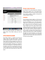
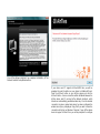
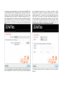
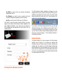
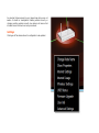
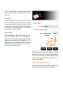
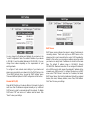
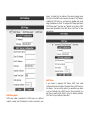
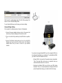
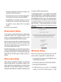
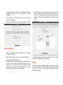
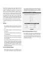
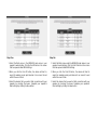
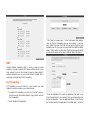
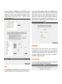
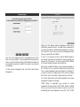
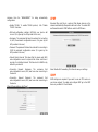
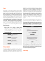
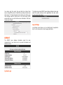
Contents
AirTies Documentation
1
Manual Overview
1
Safety and Maintenance
1
Installation for Apple Users
1
AirTies Access Points
1
AirTies Network Assistant
3
Minimum System Requirements
3
Installation
3
Running AirTies Network Assistant
6
Network Display
6
Settings
8
Change Node Name
9
Show Properties
9
Internet Settings
9
Internet Usage
10
Wireless Settings
10
USB Status (If your device has USB Host)
10
Firmware Upgrade
11
Software Upgrade
12
User Info
12
Advanced Settings
12
Adding AirTies Devices
12
Advanced Settings
12
Homepage
13
INTERNET SETTINGS
14
Access Control
NAT
29
33
Internet (WAN) Status
14
Port Forwarding
33
Internet Settings
14
DMZ
34
DNS Setting
14
MAC Cloning
15
Static Routing
34
15
WAN to VLAN Mapping
35
LAN SETTINGS
IP and DHCP Settings
ROUTING
34
15
MANAGEMENT
35
Disable DHCP (Off)
16
UPNP
37
DHCP Server
16
IGMP
37
DHCP Relay Agent
17
AirTies Media Server
38
DHCP Client
17
For Samsung DLNA compatible TVs
38
LAN Clients
18
For Sony PlayStation 3
39
VLAN Configuration
19
For Sony Bravia DLNA compatible televisions
40
Port Configuration
20
DDNS
41
Wireless Network Settings
20
QoS
42
Access Point
20
Tools
44
Universal Bridge
21
Firmware Update
44
Wireless Security Settings
24
Time Setting
44
WPA2 Security Settings
24
WEP Security Settings
24
System Logs
45
MAC Filtering
25
Log Settings
45
MESH
25
FIREWALL Settings
29
REPORT
45
AirTies Documentation
This manual has been prepared by AirTies Wireless Networks
Corporation. All rights reserved.
Manual Overview
This manual guides you through the steps necessary for setting up
and configuring your AirTies device. Please read this manual
carefully before beginning the installation process.
The Warranty does not cover failure or damage as a result of not
following the instructions in the manual. AirTies will not be held
responsible in such circumstances.
The User Manual is an important resource you can refer to for safe
and proper use of your device. Please retain it for future reference.
Safety and Maintenance
• To clean the exterior of the device use a dry cloth. Do not
attempt to clean the interior. There are no user serviceable
components inside.
• For information regarding the installation and configuration of
the device consult the remainder of this manual.
Installation for Apple Users
AirTies Access Points
Unpack your device and plug in the cables according to the Quick
Start Installation Guide.
Use either a network ( Cat5 ) cable connected directly to your Apple
Mac computer.
Open up the 'Network' panel in the Apple Mac's System Preferences
and enter the following:
Configure IPv4: Manually
• In order to prevent damage to your device, be sure to keep it in
its original box during transportation.
IP Address: 192.168.2.2
• The device must be used solely with its original power adapter.
Please note that the adapter is 220V only. Do not use with
110V AC.
Router: 192.168.2.1
• Do not insert a PSTN (phone) plug into the LAN port.
• If you encounter any problems, do not open or disassemble the
device. Call AirTies Technical Support.
• In order to prevent electric shock, do not operate the device in
wet or damp areas.
• In the event of a gas leak, do not use the device. Do not turn
the device on or off. Do not plug or unplug the power cord.
• Avoid using the device in dusty environments. If dust buildup
should occur, use a dry cloth to remove the dust.
Subnet Mask: 255.255.255.0
Click Apply.
From the Web UI you can access all of the devices configuration
options including wireless settings. For more detailed information
about the Web UI please see the User Manual for the individual
products.
After applying the settings, open up the Apple Safari Web Browser
and enter the following address in the address bar:
http://192.168.2.254
The AirTies Web User Interface (UI) will be displayed. You can log
into the Web UI using a blank password. If you cannot connect to
the device then reset the device by holding down the reset button
on the back of the device for several seconds, until all the LEDs
flash. Attempt to login again once the Access Point has restarted
(due to the reset).
Minimum System Requirements
Any of Windows XP SP2 or greater, Windows Vista and Windows 7
operating systems installed on the PC. AirTies Network Assistant
runs when Windows starts up and continues to monitor the network
for any changes or problems. If problems are discovered then
troubleshooting will fix the problems.
Installation
Note: You are strongly recommended to add a password to the
wireless network to stop intruders accessing your Local Area
Network.
AirTies Network Assistant
AirTies Network Assistant is an application that will setup and
configure, monitor and manage home networks. It has been
specifically designed to enable non technical users to perform tasks
that are important to effectively managing the home network. Your
AirTies product will be provided with a CD that contains the AirTies
Network Assistant application. Alternatively you can download the
latest version from www.airties.com. AirTies Network Assistant can
be installed on as many PCs as you would like and can also be used
to monitor networks that do not contain AirTies devices, although
many key features will be missing because they require AirTies
devices.
During AirTies Network Assistant installation your AirTies device will
be setup and configured. Insert the CD that came with your AirTies
device into the CD ROM drive of your PC, after a few seconds the
animation will run. Select the product category and product that you
want to configure from the menu. After selecting your product's
name an animation shows your box contents. Ensure that the box
contains everything shown in the animation and then click the
"Next" button. Follow the animation showing how to configure the
cabling of the product. Ensure that you follow the cabling for your
product according to the animation. After the cabling animation has
completed AirTies Network Assistant is installed. Setup application
will display terms of End User Agreement. If you have a printer
connected to your computer, you can print terms of use agreement
clicking "Print" button. Click "Yes" button to pass next step or click
"No" button to end your installation.
Once AirTies Network Assistant has completed installation, AirTies
Network Assistant Setup Wizard will run.
If your device and PC supports AirTouch/WPS then you will be
prompted to press the button on your device to initialise AirTouch.
Press the AirTouch button on your AirTies device and click the
AirTouch button. A secure connection will be initialised between the
AirTies device and PC running AirTies Network Assistant, which
includes an automatically generated wireless key. Once the wireless
connection has been created and device has been configured the
wireless security key is displayed. Copy this if you want to share the
connection with other non Windows 7 devices. If your AirTies device
does not support AirTouch then you will be prompted to configure
the wireless security manually for your device. Select WPA/WPA2 as
the Security Mode. This is the highest level of security that you can
configure. Enter a Wireless Network Name (SSID). This is the name
that appears when you search for wireless networks from a PC.
Enter a password for the wireless network. This should be at least
eight characters long. You can see the characters by unchecking
Hide characters. Click "Next" for saving your sets and passing next
step.
with configuration options for your Internet connection. These
settings will be based on settings received from your Internet
Service Provider (ISP). If you want to connect with ADSL connection,
click "ADSL", if you want to connect using WAN Ethernet, click
"Ethernet" option or if you want to 3G connection, click "3G" option
as your Internet connection type that your device supports. If you
experience any problems connecting to the Internet then it is
recommended to contact you Internet Service Provider.
A screen will appear to say that the wireless network settings have
been configured. Click "Next" button. Now you will be presented
The following settings should be configured if your device supports
features.
• For ADSL you need to enter your username and password
supplied from your ISP.
• For Ethernet you need to choose a protocol and enter
username and password supplied by your ISP if needed.
• For 3G you need to enter the PIN from your 3G SIM card.
Click "Next" to save the Internet connection settings. The screen
appears that indicates AirTies Network Assistant application has
been installed successfully. If you want to save your device to
AirTies database and take advantages of AirTies services, fill in the
relevant sections.
The AirTies Network Assistant application will always run in the
background and can be accessed by clicking the AirTies logo in the
notification area (bottom right corner, next to the clock). AirTies
Network Assistant starts every time the PC starts, allowing for the
network to be continually monitored.
If you want to exit AirTies Network Assistant then you must right
click the AirTies logo in the notification area and select "exit". If
AirTies Network Assistant is not running and you want to run it then
you must select the AirTies Network Assistant application from the
start menu under All Programs > AirTies Wireless Networks >
AirTies Network Assistant.
Network Display
The network display is the central component of AirTies Network
Assistant. Here all devices on the network are displayed with
information about each device, status of network connection and
problems with the network. Once AirTies Network Assistant has
been installed and the connection between your PC and your AirTies
device has been configured then the network display will be shown
to the user. For normal usage when AirTies Network Assistant starts
the network display will be shown.
Running AirTies Network Assistant
You can change application language by clicking "Language" icon
on the top right corner of AirTies Network Assistant application and
you can be informed by clicking "About" icon. Your router is the
device that has a connection to the Internet. It is the device that
connects the home network to the Internet and is usually a gateway
device such as an ADSL modem. There should only be one routing
device on your network and this device is placed in the middle of
the AirTies Network Assistant network display. From the router the
Internet and local network device are connected. A green line
indicates that a device is connected. A red line indicates that a
device is not connected. As new devices are added to the network
they will appear on AirTies Network Assistant. If a device is removed
from the network then it will disappear from the network GUI after it
has been disconnected for four hours. Dotted lines indicate a
wireless connection and non dotted lines indicate a cable
connection. A red cross on the line indicates that there is a problem.
Clicking this will launch the trouble shooter application, which will
identify the problem and attempt to solve it.
The network map should be updated automatically as new devices
are added to the network. However, if the network map is not
accurate then a manual refresh can run by clicking the refresh
button on the top right of the screen. Each AirTies product will be
displayed with their image on the network map. Non AirTies devices
will be displayed with a generic image. It is not possible to manage
non AirTies devices but the device can still be displayed on AirTies
Network Assistant. If you see the following icon on the network map
next to an AirTies product then the software on the device can be
updated by clicking the icon.
Any devices that are present on your network map but you are not
aware of should be investigated. Enabling wireless security or
changing existing wireless security (see below) will ensure that
intruders cannot continue to access your network.
Settings
Clicking an AirTies device allows for configuration to be updated.
Change Node Name
Internet Settings
Each device has a name, which is either the host name or the IP
address. The node name can be updated to make it easier to keep
track of devices on the network. For example, a games console may
show on the network map as an IP address like 192.168.2.55 but
can be renamed to be "games console 1".
The Internet settings for the AirTies device can be configured. The
connection type can be selected from either ADSL or Ethernet. For
ADSL connections the username and password that is supplied from
your Internet Service Provider (ISP) is entered with VPI/VCI settings
if they are not the default for your country. For Ethernet
connections the protocol is defined and username and password are
configured if PPPoE is defined.
Show Properties
The properties can be displayed for each device. Properties for
AirTies devices are displayed: Properties for local computer running
AirTies Network Assistant are displayed:
Click OK to save your settings. Click Advanced to show all Internet
settings. Click Cancel to cancel any changes made and return to the
network map.
Internet Usage
The amount of data that is sent and received from and to the
Internet is counted and stored on the gateway device. This allows
for users to monitor how much data they are using, which is useful
when they have an account with their ISP which limits the amount
of data that they can download and upload. To see the download
and upload data in real time click Real-Time.
Wireless Settings
The wireless settings of the device can be changed: The security
mode can be changed to either "None" or "WPA/WPA2". The
Wireless Network Name (SSID) can be changed. This is the name
that appears when you search for wireless networks from a PC. The
password used to connect to the wireless network can be changed.
This should be at least eight characters long. You can see the
characters by unchecking Hide characters.
Click "OK" to save your settings. Click "Advanced" to show all
Internet settings. Click "Cancel" to cancel any changes made and
return to the network map. Note that for devices that are connected
via MESH changes made to the gateway will be propagated to all
devices connected via MESH.
USB Status (If your device has USB Host)
USB status shows whether a printer or USB disk is inserted into the
device. For disks the amount of free disk space is displayed:
For printers the printer model is displayed:
Firmware Upgrade
AirTies Network Assistant will automatically check for new firmware
updates for devices. If new firmware is available then an icon will be
displayed on the device to let the user know that there is new
firmware available. Clicking on the icon will perform a firmware
upgrade on the device.
Adding AirTies Devices
When another device is added to the network then it will be
displayed in the network map. If the new device is an AirTies device
then the user s prompted to register the device.
A manual update can also be made by selecting "Firmware
Upgrade". A check will be made for new firmware: If no firmware
was found then the user will be informed: If new firmware is
discovered then the firmware on the device will be updated.
Software Upgrade
For the local PC there is a software upgrade option instead of
firmware upgrade. This will check for any newer versions of AirTies
Network Assistant and update if the user requests.
User Info
Registering a device provides AirTies with useful information that
we use to help the customer with if they have a problem and also
use to help us improve our products and customer experience. Each
AirTies device on the home network can be registered with AirTies.
If a user does not want to register then they can select 'Do not
register' from the drop down box. Click "OK" to save your settings.
Click "Cancel" to cancel any changes made and return to the
network map.
Advanced Settings
Advanced settings open the devices' Web configuration page and
allow for all other settings to be updated by the user (see settings
below).
The user can choose not to register the device, register as a new
user or use an existing user's details that already have devices
registered to them on the network. Clicking "OK" registers the new
device. Clicking "Cancel" closes the prompt.
Advanced Settings
You can set the basic settings of the device, which are ADSL and
wireless settings, with the Easy Installation CD. The easy installation
CD allows for quick and easy installation when you first setup your
device. There is also a web interface to the device that allows for
basic and advanced settings to be configured. You do not need to
be connected to the Internet to access the device's Web UI. To
connect to the device follow these steps:
For Gateway Devices the IP address will be 192.168.2.1
1- Run a Web browser program on your computer (Internet
Explorer, Mozilla Firefox etc. ).
2- In the Web Browser's "Address" field, write the address
192.168.2.1 which is the default web interface address of device
and press "Enter"
3- The "Welcome" screen of the Web Interface will appear. On the
screen you will see a dialog box asking for the password to be
entered. By default there is no login password for your device.
Leave the password fiend empty and click OK.
For Access Points the default IP address is 192.168.2.254 if no
DHCP server is discovered on the network.
If a DHCP Server is discovered on the network then you need to
discover the address of the device. This can be done as follows • Windows users should use AirTies Network Assistant
• Windows users can locate the device under Network and select
properties
• Non windows users should log into their existing gateway and
view the LAN / DHCP settings to see what IP address has been
giving to the AirTies device. The device name will appear in the
list of clients.
Note: To set a password on the login screen, read "MANAGEMENT"
under the "Password Settings" section
Homepage
After the splash screen is the "Homepage" screen. You can see the
information about the current working status and the general
settings at your homepage screen.
1. When you click "Internet Settings", you will see a table which
shows your device's default PVC connection.
2. NAT and Firewall can be enabled or disabled from the "Internet
Settings" page, by default these are enabled and should be
enabled under normal operation. To configure your internet
connection settings click the "Edit" button.
INTERNET SETTINGS
Internet (WAN) Status
When you click the "INTERNET" menu item the Internet WAN page
Status will be displayed.
Here you can see detailed information about the Internet
connection and upstream / downstream data transfer rates.
Internet Settings
When you click "Internet Settings" from the "INTERNET" a menu
showing your default WAN settings will be displayed. Please, follow
these steps for making your device's internet settings:
3. First of all, you should know to support which from PPPoE,
DHCP, Bridge or Static protocols. According to the protocol,
Internet Service Provider should give you to the information
that you need. After you fill the informations in the interested
area, click "Save".
DNS Setting
For advanced users there is the option to adjust your DNS settings.
When you click "DNS Setup" from the "INTERNET" a page giving you
the option to specify two DNS servers is displayed.
By default the checkbox "Use ISP assigned DNS Servers" should
always be selected. If you want to specify your own DNS servers
then you can uncheck this checkbox and specify your own primary
and secondary DNS servers by entering the IP address of each
server.
Click "Save" to complete the DNS setup.
MAC Cloning
You will see that "Mac Cloning" submenu, under the "INTERNET"
menu on your device's web interface.
In this page, MAC address and Hostname can be set manually and
MAC address can be also cloned automatically.
LAN SETTINGS
Any device that you connect to your router, such as PCs, network
printers, IP cameras, etc., are clients. Any operation related to
clients that will have a local network connection to your router can
be done through the "LAN" menu of the Web interface and its
submenus.
When you click on the "LAN" menu, the "LAN Client List" screen will
come up. All clients that are connected to your router and their
connection details are shown on this screen.
IP and DHCP Settings
Each client that is connected to your device takes a local IP address
(Internet Protocol Address). The device's module which distributes
IP address informations is called DHCP (Dynamic Host Configuration
Protocol). You can configure the IP and DHCP Settings of your
device, from the IP and DHCP Settings submenu under the LAN
menu.
DHCP Server
You can change the IP address and Netmask of your device in the
"Local IP Configuration" table. The default IP Address of your device
is 192.168.2.1, and the default Netmask is 255.255.255.0. You can
change these values depending on the requirements of your
existing network.
To configure IP and network mask settings of your device and
devices are connected to your network, click the "Edit" button in the
"IP and DHCP Settings" menu. You see the "DHCP Settings" menu.
There are 4 different options for DHCP configuration in this section.
Disable DHCP (Off)
Stops all DHCP activity on the device. When in this mode, the clients
must have their IP addresses assigned manually or by a different
DHCP server in order to communicate with the network. To disable
DHCP select "Off" and enter an IP address and Net mask. Click
"Save" to save your settings.
DHCP Server mode configures the device to assign IP addresses to
connecting devices. There must only be one DHCP Server on the
network, which in most cases will be the router. DHCP is enabled by
default. In this section you can assign an address range from which
your device can assign local IP addresses to clients and the lease
time. The default IP address range is 192.168.2.2 through
192.168.2.254. Maximum lease time for an assigned IP address is
set as 3600 seconds, which means the assigned IP address will be
renewed every 3600 seconds. To configure the device as a DHCP
server select "DHCP Server" and enter an IP address, Net mask,
DHCP Server Name, Start and End addresses that will be assigned
devices, Net mask, Gateway Address, Lease Time, DNS Address.
Click "Save" to save your settings.
device. To enable this, the address of the device (modem, server
etc) that runs the DHCP service needs to be known. If DHCP Relay is
enabled the DHCP server on your device is disabled and cannot
assign IP addresses to clients. To configure DHCP Relay Agent select
"DHCP Relay Agent" and enter an IP address for the device, DHCP
Server name and address of the DHCP Server. Click "Save" to save
your settings.
DHCP Client
DHCP Relay Agent
DHCP relay makes it possible for a DHCP server on a different
network to assign local IP addresses to clients connected to your
If your device is supported this feature, DHCP client mode
configures the device to obtain an IP address from a DHCP server on
the network . You can use this option if you would like your device
to get an IP address from a DHCP server on the local network. You
also have to specify which VLAN is to be the listening interface.
Click "Save" for your settings to take effect.
LAN Clients
If the device is configured as a DHCP server then you can see a list
of all the clients connected to the device. Select LAN Client under
the LAN menu of the Web Interface. Through this menu, you can
also reserve an IP address for a client. When an IP address is
reserved for a client, it cannot be assigned to any other client.
Whenever the client connects to the router, it gets the IP address
reserved for it. Click the reserve button next to a dynamic address
to reserve this as a static address.
You can see the IP addresses that are reserved in the "Static
Addresses" table. "Dynamic Addresses" table shows the IP
addresses assigned but not reserved. To new static address click
"New". Enter the Name, MAC Address, IP Address and select the
LAN. Click "Save" to create the new static address.
A list of VLANs will be shown. By default there will be a single VLAN
named VLAN 1. This is the entire network.
To create a new VLAN click New VLAN.
VLAN Configuration
If your device is supported this feature, you will see the VLAN Status
and you can configure VLANs.
Virtual Local Area Networks (VLANs) separate a single physical
network into multiple logical networks. A reason why you may
create a VLAN is if you want to separate your network for security
reasons, your guests can use one VLAN and you can use another.
By default the device is configured to operate over a single VLAN.
To configure VLANs select VLAN Configuration under the LAN menu.
Enter a VLAN Name and VLAN Id for the new VLAN. Select the ports
that you want to add to the VLAN (Ethernet ports, wireless ports).
Click "Save" to save your changes.
To add or remove ports from the VLANs select Edit from the main
VLAN menu for the VLAN that you want to update.
Wireless Network Settings
From Advanced Settings in AirTies Network Assistant, when you
click the WIRELESS menu, you will be in the Wireless Connections
screen that lists all the wireless clients connected to the AirTies
device, grouped by wireless SSID.
The Wireless Network Active box lets you enable or disable the
wireless feature of your device. By default this is enabled.
From the list of selectable ports select the port that you want to add
and click ">>". Select "Save" to save your changes.
Note that a port can only be a member of one VLAN at any time so
if you want to add a port to a VLAN you must first remove it from
any VLAN that it is currently configured to use.
Port Configuration
If your device is supported this feature, you can configure to tags on
each port to allow data to be separated to different VLANs.
Select Port Configuration from the LAN menu.
Go to Wireless Settings under the WIRELESS menu to configure your
wireless network.
Access Point
To enable the Access Point feature you must select Access Point
from the Operating Mode drop down box.
For each port the tagging can be configured to add or remove a
VLAN tag. Data can also be filtered based on untagged and
unregistered frames. Click "Save" to save your changes.
automatic adjustment of data transfer rate based on distance
and signal quality.
Universal Bridge
The Universal Bridge feature allows for any device with an Ethernet
port to be wirelessly connected to an existing Access Point. This
allows for devices such as Set Top Boxes, Connected TVs and
printers to be connected to an existing Wi-Fi Access Point.
To enable the Universal Bridge feature you must select Universal
Bridge from the Operating Mode drop down box.
Note that the device can be in either Access Point mode or Bridge
mode. When Bridge mode is enabled the Access Point feature on
the device is disabled.
• In the Frequency field you can choose whether to use 2.4Ghz or
5Ghz (if your device is supported).
• In the Mode field, you can choose the wireless mode the device
will operate in.
• In the Channel field, you can specify the frequency the device
will broadcast in. If you are using 2.4Ghz then it is
recommended that you choose one of 1, 6, or 11 as the
channel number.
• Power displays the total transmitted power from your device.
• Bandwidth field allows you to specify whether to use 20MHz or
40MHz. When in 802.11n mode. 40MHz should be selected to
achieve 300Mbps wireless data rates
• You can assign a name to your wireless network by entering
the name in the Primary SSID field. This name is broadcast by
your device.
• Rate shows the highest wireless data transfer rate supported
by your device. It is set to Auto by default. This allows for
A search will be made for existing Access Points. After
approximately 30 seconds a list of Access Points that have been
found are displayed with the signal strength and security of each
one.
From the list select your Access Point that you want to bridge with.
When you select the Access Point you will be prompted for your
password if a secure connection has been configured on the Access
Point. Enter the password and click Connect.
The device is now configured as a bridge device. Connecting a
device using a network cable will bridge the device to the wireless
Access Point that you configured. The device should not be
connected by cable to the Access Point that it has been bridged
with otherwise your network will not function correctly.
Note that the IP address of the device may change. AirTies Network
Assistant can be used to find your device and reconfigure if
necessary. Alternatively you can connect a computer directly to the
device to connect and configure the device.
If you want to turn your device back into Access Point mode then
you need to do this from the Wireless Settings menu.
Manual Mode
A warning will be displayed, informing the user that wireless Access
Point will be disabled and that they will only be able to connect to
the device with an Ethernet cable. Click OK to save the changes and
enable Universal Bridge mode.
If your SSID is hidden then you need to configure the Access Point
using manual mode. Underneath the list of SSIDs you can manually
enter the SSID, security mode and password of your existing Access
Point.
Click Connect to enable bridge mode. Click OK at the warning. The
device is now in Universal Bridge mode.
To use Universal Bride you must change your device cabling:
Universal Bridge Cabling
First complete the cabling process as shown in the diagrams.
1. Connect the power adapter inside your box to the power inlet
socket of your device and plug into the electric socket.
2. Turn on the Air 4410 by switching the On/Off button to position
"1".
3. Connect the Ethernet cable inside your box to the Air 4410's
Ethernet port and connect the other end to the Ethernet
enables device that you want to connect to your wireless
network.
If your device is supported multiSSID, up to four separate SSIDs can
be configured. By default one is configured. To add additional SSIDs
you need to check the Enabled check box.
• Primary SSID is the name that the wireless device broadcasts.
This is the name that can be seen on computers when you
select what wireless device to connect to.
• Checking the Hidden SSID box will hide your SSID during
broadcast. This is not recommended since hiding the SSID will
prevent laptops from seeing your network within their range.
• Checking User Isolation will prevent clients connecting to your
network from connecting to each other.
• The security level can be set in the Security drop down box.
This should be set to the highest security level WPA/WPA2.
• The passphrase for the wireless connection is set in the
"Passphrase" section. This should contain at least 8 characters.
• It is possible to set up 4 wireless SSIDs to have multiple
networks.
Click "Save" to store your settings.
to be able to use WPA2 ( www.microsoft.com ).
To enable WPA2 encryption: 1. Go to Wireless Security Settings
under the WIRELESS menu of the Web interface of your device. 2.
From the Security drop down box of the first SSID select WPA2. 3.
Select WPA/WPA2 from Security Type. 4. Enter a Passphrase that is
8 to 63 characters long (use a combination of letters and digits) in
the Passphrase field. Make sure you choose a key that is not easy to
guess. Click Save. 5. You must activate WPA2 and set the same
network key in all the devices that will communicate with your
AirTies device.
Wireless Security Settings
It is not necessary to configure wireless security to enable wireless
communication. However, due to growing importance of data
security, it is strongly recommended that you choose one of the
security protocols described below that best fits your needs.
Wi-Fi Protected Access (WPA), WPA2, and Wired Equivalent Privacy
(WEP) are wireless encryption protocols used to encrypt the data
traffic within the wireless network. It is recommended that you use
the most secure standard, which is WPA2.
MAC Address Filtering allows you to control which network cards can
connect to the AirTies device and share your Internet access. For
your wireless network security, it is recommended that both MAC
Address filtering and WPA2 wireless encryption protocols be
activated.
WEP Security Settings
WEP is less secure then WPA and should only be used if your PC's
wireless card does not support WPA. To configure WEP secutiry:
WPA2 Security Settings
1. Go to Wireless Security Settings under the WIRELESS menu of
the Web interface of your device.
WPA2, defined by the IEEE 802.11i standard, is one of the latest
wireless encryption methods. If you would like to use WPA2 in your
wireless network, all the wireless adapters in your network should
support WPA2. For Centrino platform computers, it is necessary to
download the WPA2 updates for the Windows XP operating system
2. From the Security drop down box of the first SSID select WEP.
3. Select Open for Authentication Mode.
4. For WEP Security Type you can select: a. 10 Hexadecimal
characters (A-F and 0-9) for 64-bit encryption. b. 5 ASCII
characters for 64-bit encryption. c. 26 Hexadecimal characters
for 128-bit encryption. d. 13 ASCII characters for 123-bit
encryption.
5. You can enter up to 4 network keys and choose the one you
want to use. Click Save.
6. You must activate WEP and set the same network key in all the
devices that will communicate with your AirTies device.
5. To add devices that will be blocked from accessing the wireless
network: * Select Just Deny MAC Addresses in MAC List. * For
each device to be blocked, enter the wireless MAC address of
the device in the New MAC Address field and then click the ADD
button.
6. Click Save.
MAC Filtering
1. Click on MAC Filtering under the WIRELESS menu of the Web
interface of your device.
2. Select the SSID that you want to configure MAC Filtering for.
3. Check the Enable MAC Filtering box.
4. To add the devices that will be permitted to access the wireless
network: * Select Just Allow MAC Addresses in MAC List. * For
each device to be allowed access, enter the wireless MAC
address of the device (e.g."00-14-38-15-60-DD") in the New
MAC Address field and then click the ADD button.
Your AirTies device supports 802.1x Authentication protocol as well.
For detailed information about how to setup 802.1x security, please
check the AirTies Website at www.airties.com .
MESH
AirTouch technology automatically configures two devices to create
a MESH. Simply push the AirTouch button on the two devices that
you want to configure a MESH between. MESH can also be
configured manually.
AirTies Mesh Technology resolves weak wireless signal and
coverage area problems often encountered in multi-story concrete
buildings. To extend wireless coverage area, it is necessary to use
AirTies access point devices functioning in repeater mode. The
access points function as repeaters and communicate with each
other via a special protocol that maintains the signal strength over
long distances and through barriers such as concrete walls.
Computers connect to all devices through the Mesh Network. This
way, the wireless coverage area can be extended to the maximum
while any signal strength problems through barriers are resolved.
Floor_1. Enter the channel that the mesh network will use in the
Channel field. We recommended you use 1, 6 or 11. While the
Mesh Network is set up manually, the AirTouch box must not be
checked. Save your settings by clicking Save.
The following steps will help you set up a Mesh Network with your
modem:
Important:
a. Your modem and repeaters must all operate on the same
channel. Therefore, it is recommended you to use channels 1, 6
or 11.
b. Your modem and repeaters must also all operate at the same
security level.
c. The signal level received at the location of the repeaters must
not be below medium.
d. Repeaters must be in DHCP client mode and your modem must
be in DHCP server mode. You can check this in the LAN menu
of the web interface.
e. In the following example, the SSIDs are called Floor_1, Floor_2
and Floor_3. This type of naming system has been used to help
your understand the procedure. But in practice we recommend
you use the same name for all SSIDs. For example, if they are
all called AirTies, users can automatically connect to the device
with the best signal strength.
Step One (Configuring the Modem):
1. Enter the Wireless Settings section of the WIRELESS main menu
in the device's web interface. Change the SSID name to
Step Two (Configuring the Repeater on Floor_2):
1. Enter the Wireless Settings section of the WIRELESS main menu
in the device's web interface. Change the SSID name to
Floor_2. Enter the channel that the mesh network will use in the
Channel field. The AirTouch box must not be checked. Save
your settings by clicking Save.
Step Three (Configuring the Repeater in Floor_3):
1. Enter the Wireless Settings section of the WIRELESS main menu
in the device's web interface. Change the SSID name to Floor 3.
Enter the channel that the "mesh network" will use in the
Channel field. The AirTouch box must not be checked. Save
your settings by clicking Save.
Step Four:
1. Select the Mesh menu in the WIRELESS main menu in your
modem's web interface. Click on the Find AP button in the
screen that has opened called MESH Settings.
2. When you click the Find AP button, the device will begin
searching for wireless access point devices it can connect to
and will list the ones it finds.
3. Select the access point or points that you want a Mesh
connection with your modem by checking the boxes. In the
access points you selected, the signal level must be at least
medium or higher. Complete the Mesh settings of your modem
by clicking the Save button.
Step Five:
Step Six:
1. Select the Mesh menu in the WIRELESS main menu in your
repeater's web interface. Click the Find AP button in the screen
that has opened called MESH Settings.
1. Select the Mesh menu under the WIRELESS main menu in your
repeater's web interface. Click the Find AP button in the screen
that has opened called MESH Settings.
2. When you click the Find AP button, the device will start to
search for wireless access point devices it can connect to and
will list the ones it finds.
2. When you click the Find AP button, the device will start to
search for wireless access point devices it can connect to and
will list the ones it finds.
3. Select the devices that you want a Mesh connection with your
repeater by checking the boxes. Complete your repeater's
Mesh settings by clicking the Save button.
3. Select the devices that you want a Mesh connection with your
repeater by checking the boxes. Complete your repeater's
Mesh settings by clicking the Save button.
You can allow or block Internet access for any computer on your
local network using the Access Control feature. These access
restrictions can be based on IP address as well as MAC address.
Access Control is enabled by default.
To define a new access rule, click "New".
FIREWALL Settings
A firewall prevents unauthorised Internet users from accessing your
local network and your computer.
AirTies Firewall has a SPI, Stateful Packet Inspection, feature. SPI
monitors the protocol and packet addresses being received to
determine if the information should be passed through the firewall
to the connected computers on your network. The Internet
addresses that are a source of malicious attacks are permanently
blocked from accessing your network.
You can also limit or block the Internet access of any local user by
defining advanced rules for Internet access.
Firewall is activated by default.
The following sections describe the submenus under the FIREWALL
menu of the web interface.
Access Control
On the page that appears:
1. Enter a name for the access rule you would like to define in the
"Rule Name" field. Choose a name that is easy to remember.
2. If VLAN is implemented then select the LAN or WAN interface,
otherwise take the defaults.
3. In the "SELECT CLIENT" section you can enter the IP or MAC
addresses of the clients whose access you would like to restrict
with this rule.
4. Access control can be defined based on local IP or MAC address
(uniquely identifies the network adapter of the device). If an
access rule is defined by MAC address, the rule defined for the
device will be valid even if the local IP address changes.
5. It is possible to enter the MAC or IP addresses individually or
choose them from the list of client devices in the local network.
6. Enter the MAC address of the device you would like to restrict
traffic from in "New MAC Address" or IP address of the device
in the "New IP address range" field. For a single IP address,
enter the same value in the two boxes that define the range.
(e.g. 192.168.2.2 and 192.168.2.2). To restrict access for all
devices in an IP address range, enter the beginning and ending
IP addresses (e.g. 192.168.2.2 and 192.168.2.50). Click the
"Add >" button to add the device to the restricted list.
9. To define a new application, click the "New" button.
10. Enter a name for the application you are defining in the
"Application Name" field.
11. Enter the WAN port for the application in the WAN TCP and UDP
fields.
7. Select "Block all traffic" to block all traffic to and from the
Internet interface.
8. To block an application select an application from the list and
click "Add>" to add the application to the restricted application
list.
12. Enter the internal port number that the application will use in
the local network in the LAN TCP and UDP fields.
13. Click "Save".
2. Enter a new MAC address or choose one from the list of existing
clients and click "Add >".
3. Click "Save".
14. The new application definition will be added to the existing
applications list.
15. A schedule for your rule can be specified. By default the rule
will be always enforced. Enabling "Scheduling", entering a start
time and end time and selecting days of the week will only
enforce the rule during the specified time.
16. Click "Save" to create the rule.
MAC Filtering
MAC Address Filtering allows you to block Internet access based on
MAC addresses. When this feature is activated, you can specify the
MAC addresses of the computers that will have Internet access
blocked.
1. Check the "Enable MAC Filtering" box.
URL Filters
You can block access from any computer on your local network to
the websites you specify by entering the URL or any keyword that is
part of the URL that you would like to block.
1. Check "Enable URL Filter".
2. Enter the IP address or MAC address of the computer that you
want to provide URL filters for.
Anti-DoS
The Anti-DOS feature prevents "Denial of Service" attacks that aim
to disable your router by flooding it with connection requests. On
this page, you can set the maximum number of connections that
will be allowed from the Internet for a specified time interval for
each protocol.
Anti-DOS is enabled by default.
3. In each of the boxes enter the keywords that you want to block
or enter the compleye URL.
4. Click "Save" to save.
" Click "New" to forward a port. " In the "Rule Name" field, assign a
name for the Port Forwarding rule you are creating. " If use are
using VLANs then select the VLAN that you want to apply the port
forwarding rule for. If you are not using VLANs then take the default
values. " Either select the client from the list of existing LAN clients
or enter the IP address in the "New IP Address" field. Click "Add >"
NAT
Network Address Translation (NAT) is a way to map an entire
network to a single IP address. NAT allows multiple clients in your
local network to access the Internet through a single global IP
address assigned to you by your Internet Service Provider. NAT is
commonly used together with Port Forwarding.
Port Forwarding
Port Forwarding is used in order for a host outside your local
network to access a machine on your local network.
1. To enable Port Forwarding on a port, go to the "NAT" menu on
the left menu bar of the Web interface of your device and click
"Port Forwarding".
2. Check "Enable Port Forwarding".
" From the Application List, select the application that want to use
for port forwarding. If it is not present then you will manually enter
the port configuration. " Enter an Application Name. " Enter the real
port number used by the application in the WAN fields. " Enter the
local port number for the application in the LAN fields, this can be
the same as the Real Port. " To forward a range of ports instead of a
single port, use a dash (-) sign in between. For example to forward
all ports between 23 and 80, enter "23-80". " Click "Save" to save
the port forwarding rule.
On your router DMZ is disabled by default. To enable DMZ go to the
DMZ sub-menu under NAT menu of the Web UI. Check the Enable
DMZ checkbox. Select the LAN and WAN interfaces. Select an IP
address from the drop down menu where data will be forwarded to.
Click Save to save your changes. From now all data sent to your
WAN IP address (no matter what port) will be forwarded to the IP
address that you have just specified.
ROUTING
Routing defines the rules which determine how IP packets reach
their destination on the Internet. Rules can either by automatically
created by using the Routing Informaton Protocol (RIP) or rules can
be manualy created. By default your device is configured to
automatically create routing rules.
Static Routing
If you want to manually create routing rules then go to the ROUTING
menu. A list of static routing rules will be displayed.
DMZ
The DeMilitarized Zone (DMZ) feature opens up all of the ports of a
single local network host for unrestricted access from the Internet.
To create a static rule select Static Routing option from the
ROUTING menu.
Click NEW MAPPING.
You need to enter a destination IP address and the route that will be
taken to get there: Desitnation: Enter the IP address of the
destinaton Netmark: Enter the netmask for the destination IP
address. Connection: Select the network interface where the data
will be sent. Gateway: Enter the IP address of the host that can
transfer the data for the destination IP address. Metric: Specifiy the
number of hops (how many gateways) the data needs to travel
through. Click Save to save the static route. The static route will be
displayed in the list. The static can be deleted by checking the
delete checbox.
Mapping Name: Give the mapping a name. Mapping Type: Select
either Routed or Bridged. WAN: Select a WAN interface from the list.
LAN: Select one or more LAN interfaces. Click Save to save your
settings.
If your device supported WAN to VLAN Mapping, follow next steps
below.
MANAGEMENT
WAN to VLAN Mapping
From the MANAGEMENT menu you can configure how the device is
managed.
It is possible to creating mappings to allow data from the different
WANs to be sent to differernt VLANs on your LAN. To create a new
WAN to VLAN mappig go to the WAN and VLAN Mappings menu
under ROUTING menu.
To change the password used to protect the Web UI. Select
Password Settings.
Please note that allowing remote management should only be
performed by experienced users. To enable remote management of
your device, first click the "Enable Remote Management" check box.
If you check the "Any IP" box, your router can be managed remotely
from any computer that has a WAN IP.
Enter the current password and the new password twice. Select
Save to save your settings. The new password will be required next
time you access the device settings. AirTies Network Assistant will
also request this password to allow for the device to be monitored
and managed.
To allow remote management from the Internet select Remote
Management.
If "Any IP" is not checked, you have to add the WAN IP address of
the computer from which you would like to remotely manage your
device to the "IP Access List". To do this, enter the WAN IP address
in the "New IP Address" field and click the "Add" box.
After saving, the WAN IP address you have entered will appear in
the "IP Access List". If you select this address from the list and click
"Save", remote management will be activated for this address. If
you want to remove an IP address from the list, select the address
from the list, click on the "Delete" checkbox and then click "Save".
You can also specify which services will be available to the remote
management computers on this page.
TR-069 defines an application layer protocol for remote
management of end-user devices. With TR-069, all kind of settings
that you can do with local area network connection, can be set
automatically with auto-configuration server (ACS). Click "TR-069"
submenu from
configuration.
the
"MANAGEMENT"
for
doing
automatically
• Enable TR-069: To enable TR-069 protocol, click "Enable
TR-069" check box.
UPNP
Universal Plug and Play is a protocol that allows devices on the
network automatically interoperate with each other. To enable UPnP
port forwarding select UPNP Settings under the UPNP menu.
• URL:Auto-configuration address (ACS)that your device will
connect. (It is given by the ACS provider to the user.)
• Username: The username that must be entered for connecting
to (ACS) the automatic configuration server. (It is given by the
ACS provider to the user.)
• Password: The password that must be entered for connecting to
(ACS) the automatic configuration server. (It is given by the
ACS provider to the user.)
• Periodic Inform Interval: This shows that the device and (ACS)
auto-configuration server's reciprocal link status and time in
seconds of controlling intervals. This time is set to 86400 sn by
default in your device.
• Connection
Request
Username:
The
username
that
auto-configuration server (ACS) must use when connecting to
the device.
• Connection
Request
Password:
The
password
that
auto-configuration server (ACS) must use when connecting to
the device.
After all these settings, click "Save".
Select Enable Port Forwarding. Click Save to save your settings.
IGMP
IGMP settings are required if you want to use an IPTV service on
your home network. To enable and configure IGMP go to the IGMP
menu on your Web UI. Check Enable.
The Media Server will share videos, music and photos from a USB
disk attached to the Air device's USB port. Media can be viewed on
a DLNA / UPnP AV compatible Media Player, which is connected to
the same network as the AirTies device, by locating the AirTies
media server named Airxxxx, where xxxx is the product number,
and browsing and playing the contents. Media Server can be
configured from the Web interface of your device:
1. Go to the "MEDIA SERVER" menu of your device. From here you
can enable or disable the Media Server. By default the Media
Server is enabled.
Check Quick Leave if you want to enable immediate termination of
IGMP multicast group. This will improve the quality of your IGMP
broadcast. Select the upstream network interface. This is the WAN
interface that that your router will receive IGMP packets with. There
must be at least one interface defined as upstream. The Rate Limit
sets a limit on the rate of data on the network interface. This must
be a value between 0 and 32727. The TTL value is the number of
hops on the network between the network device and the client that
will receive the IGMP packets. This must be a value between 1 and
255. The downstream network interface is the LAN interface that
the client receiving IGMP data is connected to. At least one
downstream network interface must be selected and Rate Limit and
TTL set.
AirTies Media Server
2. Click "Save" to complete the Media Server settings for your
device.
Note that the Media Server requires a USB disk to be inserted into
the USB port of your device otherwise the service will not be
enabled.
The contents of the drive can be managed using AirTies Network
Assistant or via a network path (see USB Host instructions). Any
new media placed on the drive will be shared by the Media Server.
Media Servers include DLNA / UPnP AV compatible TVs, Set Top
Boxes, Blue-ray player and PlayStation 3s. Connect your DLNA /
UPnP AV player to the same network as your AirTies device.
For Samsung DLNA compatible TVs
Turn on the TV and press the MEDIA.P or W.LINK button on your
remote control.
You can stop the media by pressing the 'stop' button on your
remote control.
On the Media Player menu on your TV you will see Photo, Video and
Music icons. Under each of these you will see the AirTies device.
Select the AirTies device to list the media that is contained on the
attached USB disk. Selecting a Photo, Video or Music file will play or
display the media on the television.
For Sony PlayStation 3
Turn on the PlayStation 3, Media Servers on the same network are
automatically detected and icons for the detected servers are
displayed under Photo, Music and Video icons.
Select the AirTies device to list the media that is contained on the
attached USB disk.
Selecting a Photo, Video or Music file will play or display the media
on the television. You can stop the media by pressing the circle
button on your controller. For movies you can see thumbnails of the
movie by pressing the square button on your controller. You can
skip to the movie by selecting the thumbnail and pressing the X
button on your controller.
If you cannot see any devices or files you may need to scan for the
DLNA devices which are on the network. To do this select 'search for
Media Servers' under either the Photo, Music or Video icons.
For Sony Bravia DLNA compatible televisions
Turn on your TV and press the 'home' button on your remote control
to open the media menu.
Scroll across the media menu and you will see Photo, Video and
Music icons. Under each of these you will see the AirTies device.
Select the AirTies device to list the media that is contained on the
attached USB disk. Selecting a Photo, Video or Music file will play or
display the media on the television.
You can stop the media by pressing the 'stop' button on your
remote control.
If you cannot see any devices or files you may need to scan for the
DLNA devices which are on the network. To do this, go to 'Settings'
menu then scroll to 'Network Settings' > 'Server Display Settings'
and then press 'Options' on your remote and select 'Update list'.
The television will scan the network and find your AirTies Media
Server.
The files that can be played on your Media Player depends upon the
codec and file container support offered by your Media Player.
Please consult your Media Player's documentation for a list of
codecs and file containers that it supports.
To use the Dynamic DNS feature you need to setup an account with
a DDNS service provider. To create a new DDNS account click New.
AirTies Media Server has been tested for interoperability on a
number of Media Players. Please visit www.airties.com for a current
list of tested devices.
DDNS
Dynamic DNS (DDNS) ensures that your hostname and IP address in
the Internet name servers are always current. It's primarily used to
associate a domain name with a dynamic IP address, making it
possible to access a computer with a dynamic IP address over the
Internet. This also allows you to run a server on a computer that has
a dynamic IP address. DDNS Settings To configure the DDNS
settings on your device go to DNS Settings under the DDNS menu of
the Web User Interface. You will see the current DDNS account
information if one is present.
Enter the following information DDNS Service Name: Select the
DDNS service provider. Hostname: Your hostname you want to
associate with your dynamic IP address. User name: The username
provider from your DDNS service provider. Password: The password
provider from your DDNS service provider. Click Save to create the
DDNS account. You will return to the DDNS Settings page again will
see your DDNS account and status. You can add additional DDNS
accounts or can edit and remote DDNS accounts.
Rules can be created to classify data. To create, edit or delete rules
to to Traffic Classification under QoS option on the menu. To create
a new rule add some of the following information in the fields.
To enable DDNS check the Enable DDNS check box and click Save.
QoS
Quality Of Service (QoS) allows you to pioritise data for certain
applications to get the best possible service for these applications.
Applications that are time senstive to the data the receive, such as
IPTV or VOIP, require QoS to be configured. To enable QoS go to the
QoS page on the Web UI.
Rule Name Source: Enter a rule name for the rule
IP Address: Enter the source address that the data will come from.
IP Address Range: Enter a range of addresses that the data will
come from.
Port: Enter the source port that the data will come from.
Port Range: Enter a range of ports that the data will come from.
MAC Address Destination: Enter the source MAC address that the
data will come from.
Select QoS Enabled to enable QoS and click Save.
Traffic Classification
IP Address: Enter the destination address that the data will be sent
to.
IP Address Range: Enter a range of addresses that the data will be
sent to.
Port: Enter the destination port that the data will be sent to.
Port Range: Enter a range of ports that the data will be sent to.
Traffic Mapping is where rules are matched to Class of Services.
Select Traffic Mapping from the QoS menu.
MAC Address: Enter the destination MAC address that the data will
be sent to.
Protocol: Enter the protocol of the data
DSCP/TOS: Enter the QoS values that the data will have.
Click Save to create a new rule. The rule will appear in the table.
Traffic Shaping
Click Add to create a new Traffic Mapping.
In the traffic shaping page you can limit the bandwidth of each
Class of Service. Go to the Traffic Shaping menu under the QoS
menu.
Enter the following information:
Source Interface: The interface on the device where the data is
coming from. For incoming traffic this will be a WAN interface and
for outgoing traffic this be a LAN interface.
There are already four Class of Services defined. The bandwidth for
each Class of Service is limited so that CoS4 is guaranteed the
highest amount of bandwidth. The minimum and maximum amount
of bandwidth of each CoS can be changed. Please note that
changing these is only recommended for advanced users. Additional
Class of Service can be created by clicking Add. The minimum and
maximum guaranteed bandwidth should be entered. Click Save to
save your settings.
Traffic Mapping
Destination Interface: The interface on the device where the data is
going to. For incoming traffic this will be a LAN interface and for
outgoing traffic this be a WAN interface.
Rule: Select a rule that you previously configured on the Traffic
Classification page.
Cos: Select a Class of Service.
Click Save to save your settings.
Traffic to and from the specified interfaes that match the rule will be
prioritieed bandwidth according to the Class of Service.
Tools
On this page, you can restart your device, reset it to factory
defaults, backup its current configuration or restore from a previous
backup. To get to the Tools screen, select TOOLS from the main
menu of the Web interface. * The Restart button restarts your router
remotely. During this operation, your connection to the router will
be lost. You can reconnect after the router comes back up. * The
Restore Factory Defaults button allows you to reset your router back
to factory defaults remotely. This will clear all the current settings
on your router. * Backup Config lets you save the current settings of
your router onto your computer. When you click the Backup Config
button, your router will create a file called config.bin to be saved on
your computer. You can restore this configuration later using the
Restore Config button.
disable this by unchecking the Enable auto firmware update and
clicking Save. You can check for updates by clicking Check For
Updates Now. The device will contact AirTies to see if there are
updates. If there are updates then they will be downloaded and the
device will upgrade. After the firmware is successfully installed, the
system will restart automatically. Therefore, connection to the
device will be lost. You will need to reconnect if you would like to
reconfigure any settings. Your router must stay ON during the
upgrade.
If you want to manually update the firmware running on the device,
go to Firmware Upgrade under the TOOLS menu. Click Browse and
locate the most recent router firmware file on your computer in the
pop-up window that appears. (You can download the most recent
firmware file from the AirTies website www.airties.com). Then click
Upgrade.
• Restore Config lets you restore a previously saved
configuration onto your router. Click the Browse button to
locate the config.bin file that was previously saved, and then
press the Restore Config button to restore your settings from
this file onto your router.
Firmware Update
Your device is configured to automatically check for updates and
update itself if it finds an update. The process to check for updates
approximately every 30 days. By default this is enabled. You can
After the firmware is successfully installed, the system will restart
automatically. Therefore, connection to the device will be lost. You
will need to reconnect if you would like to reconfigure any settings.
Your router must stay ON during the upgrade.
Time Setting
Your device gets the current time and date from Internet time
servers using SNTP protocol. Default factory settings include some
time servers. To change the time servers used by your device go to
Time Settings under the TOOLS menu. In the Time Server (SNTP)
window that come up, enter the time server information. Click Save
to save your changes.
The System Logs under REPORT menu displays detailed system logs
about the system activity and the applications that were active
since the device last started.
Log Settings
Log Settings screen allows you to set detail levels for application
logs. You can also specify a remote logging destination.
REPORT
The REPORT menu displays information about the main
characteristics of your device such as product information and
software versions.
System Logs