1
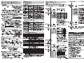
1
Adjust for Moving Workpiece without Stopping Line
Settings
Full Auto Tuning
Smart Fiber Sensor
1-1 Dimensions
E3X-HD0
If you want to set with the Communication Unit, refer to the User’s Manual provided with
the Communication Unit. See below to set with Amplifier Unit.
(Keep holding the
PRECAUTIONS ON SAFETY
4.2
10
5.1
90.8
Turns ON when Dynamic Power Control is
effective.
[OUT Indicator]
[ST Indicator]
Turns ON when Output is
ON.
Turns ON when Smart Tuning is in progress.
37
] is displayed in red digital. After the workpiece passes
through, release your finger from the
Power Tuning
When Light
Level is
Saturated
button.)
MODE
Setting Reset
→
L/D
Key Lock
UP/DOWN
MODE
31
33.4
9
Sensitivity Setting
[ ] Button
A single press each for setting
with/without a workpiece.
[ST Indicator] turns ON.
20.5
37.9
With an thin-diameter fiber
attachment (E39-F9)
Incident Light
UP
Green Digital Display Level
Red Digital Display
2-2.4 dia.
39.5
Minute Threshold
Adjustment
[UP/DOWN] Button
The green digital value changes.
90.8
Dimensions in parentheses () indicates the ones with related components.
Unit: mm
1-2 Mounting the Amplifier Unit
Warning Indications
Displays
Light ON/Dark O setting.
button while the workpiece passes through, and hold 7
seconds or longer until [
Zero Reset
5.7
Indicates a potentially hazardous situation which, if not avoided,
CAUTION
may result in minor or moderate injury or in property damage.
[DPC Indicator]
Threshold Level
20.5
Meanings of Signal Words
[L/D Indicator]
°
100 ax.)
(M
5.7
3.4
* 5 " *
button without the presence of a workpiece, and pass the workpiece
through while [
] -> [
] -> [
] is displayed in red digital.
+ : Press both
: Press both in sequence
13.8
10
4.5
2011 All Rights Reserved.
104.75 (Max. with the protective cover open)
Thank you for selecting an OMRON product. This sheet
primarily describes precautions
required in installing and operating the product.
r"TQFDJBMJTUXIPIBTUIFLOPXMFEHFPGFMFDUSJDJUZNVTUUSFBU
the product.
r1MFBTFSFBEUIJTNBOVBMDBSFGVMMZBOEVTFJUDPSSFDUMZBGUFS
thoroughly understanding the product.
r1MFBTFLFFQUIJTNBOVBMQSPQFSMZGPSGVUVSFSFGFSFODF
whenever it is necessary.
1. Hold the
2-1 Setting and Display Overview
27.1
5.2
21.7
INSTRUCTION SHEET
© OMRON Corporation
2
Installation
Mode Change
[MODE]Button
Output Switch
[L/D] Button
Switches between SET
mode and RUN mode by
a long press (3 seconds
or longer) of the key.
A single press switches between
Light ON/Dark ON. [L/D] Indicator
changes.
Setting is Completed
2-2 Switching Control Output
1. Press
Hold for 7 seconds or longer
Workpiece
Refer to " Convenient
Setting Features".
Incident light level setting: Adjust the max. incident light level on Step 1 as the power tuning level.
Threshold setting: Set to the middle between max. and min. incident light levels on Step 1.
Determine Workpiece Position
button.
L/D
PRECAUTIONS
N Mounting on DIN Track
Through-beam: Set to "Dark ON" to turn the
output ON with a workpiece in the detection area.
1. Let the hook on the Amplifier Unit's Fiber Unit
Do not use the product with voltage in excess of the rated voltage.
Excess voltage may result in malfunction or fire.
connection side catch the track and push the
unit until it clicks.
Never use the product with an AC power supply. Otherwise,
explosion may result.
1. Press
[L/D Indicator] turns ON.
NRemoving from DIN Track
Fiber Unit Connection Side Hook
2
1. Push the unit in the direction 1.
2. Lift it up in the direction 2.
PRECAUTIONS FOR SAFE USE
Position Tuning
button without a workpiece in the area.
1pnt
Workpiece
Reflective: Set to "Light ON" to turn the
output ON with a workpiece in the detection area.
1
[L/D Indicator] turns
ON.
Workpiece
2. Place the workpiece at the desired position and hold
button.
5IFGPMMPXJOHQSFDBVUJPOTNVTUCFPCTFSWFEUPFOTVSFTBGFPQFSBUJPOPGUIF4FOTPS
r%POPUVTFUIF4FOTPSJOFOWJSPONFOUTTVCKFDUUPáBNNBCMFPSFYQMPTJWFHBTFT
N Connectng Amplifier Units with
Communication Units
r%POPUVTFUIF4FOTPSJOFOWJSPONFOUTTVCKFDUUPFYQPTVSFUPXBUFSPJMDIFNJDBMTFUD
r%POPUJOTUBMMUIF4FOTPSJOFOWJSPONFOUTTVCKFDUUPJOUFOTFFMFDUSJDàFMEPSGFSSPNBHOFUJDàFME
2-3 Smart Tuning [Easy Sensitivity Setting]
1. Mount the Communication Unit and Amplifier Unit
r%POPUBUUFNQUUPEJTBTTFNCMFSFQBJSPSNPEJGZUIF4FOTPS6OJUJOBOZXBZ
r%POPUVTFUIF4FOTPSJOBOZBUNPTQIFSFPSFOWJSPONFOUUIBUFYDFFETUIFSBUJOHT
r8IFOEJTQPTJOHPGUIF4FOTPSUSFBUJUBTJOEVTUSJBMXBTUF
1. Press
Incident light level setting: The Step 2 incident level is adjusted to half the power tuning level.
Threshold setting: Set to the same value as the Step 2 incident level.
button with a workpiece in the detection area.
Detect Transparent or Small Workpiece (Set Threshold by incident light level percentage)
1pnt
3. Tighten the screw on the End Plates using a driver.
r#VSOJOKVSZNBZPDDVS5IF4FOTPSTVSGBDFUFNQFSBUVSFSJTFTEFQFOEJOHPOBQQMJDBUJPODPOEJUJPOTTVDIBTUIF
BNCJFOUUFNQFSBUVSFBOEUIFQPXFSTVQQMZWPMUBHF6TFDBVUJPOXIFOPQFSBUJOHPSDMFBOJOHUIF4FOTPS
2
r)JHI7PMUBHFMJOFTBOEQPXFSMJOFTNVTUCFXJSFETFQBSBUFMZGSPNUIJTQSPEVDU8JSJOHUIFNUPHFUIFSPSQMBDJOH
r8IFOTFUUJOHUIF4FOTPSCFTVSFUPDIFDLTBGFUZTVDIBTCZTUPQQJOHUIFFRVJQNFOU
PRECAUTIONS FOR CORRECT USE
r%POPUJOTUBMMUIF4FOTPSJOUIFGPMMPXJOHMPDBUJPOT
-PDBUJPOTTVCKFDUUPEJSFDUTVOMJHIU
-PDBUJPOTTVCKFDUUPDPOEFOTBUJPOEVFUPIJHIIVNJEJUZ
-PDBUJPOTTVCKFDUUPDPSSPTJWFHBT
-PDBUJPOTTVCKFDUUPWJCSBUJPOPSNFDIBOJDBMTIPDLTFYDFFEJOHUIFSBUFEWBMVFT
r5IF4FOTPSJTSFBEZUPPQFSBUFNTBGUFSUIFQPXFSTVQQMZJTUVSOFE0/*GUIF4FOTPSBOEMPBEBSF
DPOOFDUFEUPQPXFSTVQQMJFTTFQBSBUFMZUVSO0/UIFQPXFSTVQQMZUPUIF4FOTPSGJSTU
r0VUQVUQVMTFTNBZPDDVSXIFOUIFQPXFSTVQQMZJTUVSOFE0''5VSO0''UIFQPXFSTVQQMZUPUIFMPBE
PSMPBEMJOFGJSTU
r&YDFTTJWFJODJEFOUMJHIUDBOOPUCFTVGGJDJFOUMZIBOEMFECZUIFNVUVBMJOUFSGFSFODFQSFWFOUJPOGVODUJPO
BOENBZDBVTFNBMGVODUJPO5PQSFWFOUUIJTTFUBIJHIFSUISFTIPMEMFWFM
r"UUBDIBQSPUFDUJWFDBQPOUIFQPXFSTVQQMZDPOOFDUJOHUFSNJOBMTUIBUBSFOPUVTFEUPQSFWFOUFMFDUSJD
TIPDLPSTIPSUDJSDVJU
Percentage Tuning
1. Turn ON Percentage Tuning in SET mode.
2. Press button without a workpiece in the area.
E3X-CRT
Up to 30 Amplifier Units can be connected to
E3X-ECT Communication Unit .
Up to 16 Amplifier Units can be connected to
E3X-CRT Communication Unit.
Under environments such as vibration, use an End Plate
even with a single amplifier unit.
UIFNJOUIFTBNFEVDUNBZDBVTFJOEVDUJPOSFTVMUJOHJONBMGVODUJPOPSEBNBHF
2. Press
2pnt
Setting is Completed
Incident light level setting: The Step 2 incident light level is adjusted to the
power tuning level.
Threshold setting: Set to the value obtained by [Incident Level at Step 2 x
Percentage Tuning Level + Incident Level at Step 2].
Setting is Completed
1. Insert a Fiber Unit into a fiber cutter hole.
Fiber Cutter E39-F4
(Provided with
the Fiber Unit)
Insert a standard Fiber Unit fiber up to the
position in which it is cut; and
a thin-diameter Fiber Unit fiber to the
bottom of the hole.
Press down the blade at a single
stroke to cut the fiber.
2
] is displayed.
err
All
r Enhance the power tuning level.
r Use a thin-diameter fiber.
r Widen the emitter and receiver distance (Through-beam)
r Distance the sensor from the workpiece (Reflective)
Incident light level is too
high.
Low Error
err
1
Workpiece
The red digital display changes
Single Core
Multi Core
Tuning other than
Maximum Sensitivity
Tuning
r Decrease the power tuning level.
r Narrow the emitter and receiver distance (Through-beam)
r Locate the sensor closer to the workpiece (Reflective)
The adjustment range of smart tuning is approx. 20 to 1/100 times. When selecting giga mode as
detection function, the range will be approx. 2 to 1/100 times due to the large initial value.
Hold for 3 seconds or longer
.
Refer to "
Fiber Unit
When mounting a coaxial reflective
Fiber Unit, insert the single-core
Fiber unit to the upper hole (Emitter
side) and the multi-core Fiber Unit to
the lower hole (Receiver side).
-1-
button for 3 seconds or longer with/without workpiece as shown below.
Reflective: Workpiece is absent
position and fix the Fiber Unit.
Compatible Communication Unit (Sold Separately)
err
r Change the detection function mode to a slower
response time mode.
r Narrow the emitter and receiver distance (Through-beam)
r Mount the sensor closer to the workpiece (Reflective)
Incident light level is too low.
3
4. Return the lock lever to the original
r"NQMJGJFS6OJUr*OTUSVDUJPO4IFFUUIJTTIFFU
+BQBOFTF&OHMJTIBOE$IJOFTF
Hold
Remedy
Error Origin Tuning Type
2-point Tuning
Full Auto Tuning
Positioning Tuning
The light level difference
between Points 1 and 2 are
extremely small.
Over Error
Maximum Sensitivity Tuning
Protective Cover
4
unit hole to the bottom.
Checking the Package Content
Detect for Workpiece Presence/Absence
Thin-diameter Fiber
Attachment: E39-F9
Release the button when [
Through-beam: Workpiece is present
Lock Lever
Lock
Release
Error / Display / Cause
Near Error
1.
1. Open the protective cover.
2. Raise the lock lever.
3. Insert the Fiber Unit in the fiber
r.BLFTVSFUIBUUIFQPXFSTVQQMZJTUVSOFE0''CFGPSFDPOOFDUJOHTFQBSBUJOHPSBEEJOH"NQMJGJFS6OJUT
r%POPUQVMMPSBQQMZFYDFTTJWFQSFTTVSFPSGPSDFFYDFFEJOH/
POUIF'JCFS6OJUXIFOJUJTNPVOUFE
POUIF"NQMJGJFS6OJU
r5IF&9.$&9.$47BOE&9.$4.PCJMF$POTPMFTDBOOPUCFVTFE
r.VUVBMJOUFSGFSFODFQSFWFOUJPOEPFTOPUGVODUJPOBNPOHUIF&9%"/4%/"BNQMJGJFST*UGVODUJPOT
BNPOH&9%"4.%"NPEFMT
r5IF&9%354$PNNVOJDBUJPO6OJUDBOOPUCFVTFE
r"MXBZTLFFQUIFQSPUFDUJWFDPWFSJOQMBDFXIFOVTJOHUIF"NQMJGJFS6OJU
r%PSOPUVTFUIJOOFSCFO[JOFBDFUPOFBOEMBNQPJMGPSDMFBOJOH
1
No Smart Tuning other than Power Tuning can be used if Percentage Tuning is set.
Smart Tuning Error
Step 1 and Step 2 can be reversed.
Thin-diameter
Fiber Unit Hole x 2
N Mount Fiber Unit
Protective Cap
Incident light level setting: The larger incident level of the Step 1 and 2 values is
adjusted to the power tuning level.
Threshold setting: Set to the middle between the Step 1 and 2 incident light levels.
2
Standard Fiber Unit Hole
(dia. 2.2 mm) x 3
Detailed Settings".
per
button again without a workpiece in the detection area.
1-3 Mounting Fiber Unit
N Use Fiber Cutter
Refer to "
3
Tighten the screw while pressing the End Plate.
2.
&UIFS$"5DPNQBUJCMF&9&$5$PNQP/FUDPNQBUJCMF&9$35
2-point Tuning
1
ends of the grouped Amplifier Units to prevent them
from separating due to vibration or other cause.
r%POPUVTFUIF4FOTPSJGUIFDBTFJTEBNBHFE
.
Setting is Completed
2. Use End Plates (PFP-M: separately sold) at the both
r%POPUNJTXJSFTVDIBTUIFQPMBSJUZPGUIFQPXFSTVQQMZ
The red digital display changes
Detect for Workpiece Presence/Absence
DIN Track
on each DIN track and slide them in the direction of
arrow 1 and insert the connector until it clicks.
r%POPUBQQMZWPMUBHFTPSDVSSFOUTUIBUFYDFFEUIFSBUFESBOHFT
Hold for 3 seconds or longer
Detailed Settings" to change the powr tuning level.
2-4 Minute Adjustment of Threshold Level
1. Press
button to adjust the threshold level.
UP/DOWN
Setting is Completed
The threshold level becomes higher.
The threshold level becomes lower.
Incident light level setting: The incident level in Step 1 is adjusted to "0".
Threshold setting: The value is set to approx. 7% of the incident light level of 1.
If the incident light level of 1 is smaller during long distance etection, the
minimum value by which an output is correctly turned ON will be set.
Hold the key for high-speed level adjustment.
-2-
OCT,2009