1
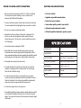
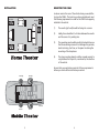
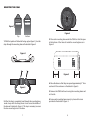
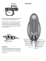
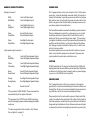
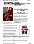
If you have any questions contact the SAS Technical Support Department at: Phone - (800) THE TUBE Fax - (225) 272-9844 In Canada: (604) 988 2966 Email - [email protected] Website - www.bazooka.com 15049 Florida Blvd., Baton Rouge, LA. 70819 CONTENTS Dear Friend, Thank you for selecting the Bazooka® Mobile Audio CS8A5 for your car stereo system. The Bazooka CS8A5 represents our continued commitment to efficiency and design. An innovative manufacturing process we developed for the Bazooka provides consumers with state-of-the-art speaker system design. At Bazooka Mobile Audio, we take pride manufacturing the most revolutionary bass speaker systems ever created, featuring our patented Bass Tubes® enclosure design, and we hope you will take pride in owning them. Several years ago, we realized that efficiency was the wave of the future in autosound, so we made a commitment to design, manufacture, and deliver the most efficient speaker systems possible. Today we market our patented speaker systems worldwide and the high quality of the Bazooka brand is well respected by consumers and dealers of all nationalities. When properly installed, Bazooka Mobile Audio systems will give you years of clean uninterrupted sound reproduction. Therefore, I urge you to take a few minutes of your time to review this instruction booklet. It was designed to give you a better understanding of our products and to explain how to apply them properly. Thank you again for choosing Bazooka. Our early commitment to quality has made them the product of choice, and I am sure you will agree that you have made the right one! Enjoy! Sincerely, BEFORE YOU BEGIN--SAFETY PRECAUTIONS FEATURES/SPECIFICATIONS INSTALLATION MOUNTING THE CS8A5 WIRING DIAGRAM HARNESS CONNECTOR DETAIL POWER WIRE GROUND WIRE REMOTE TURN ON OPTIONS L.E.D. POWER INDICATOR PHASE SWITCH SETTING THE LEVEL OPTIONAL REMOTE BASS CONTROL MODULE PG 3 PG 4 PG 5 PG 6, 7, 8, 9 PG 10 PG 11 PG 12 PG 12 PG 13 PG 13 PG 13 PG 14 PG 14 WARRANTY The CS8A5 is covered under warranty for one full year from the date of purchase. Terms and conditions of the warranty are as stated on the warranty card included in the box with the product. We recommend that you use only authorized BAZOOKA® dealers to install this product. Improper or incorrectly performed installation voids this warranty. PRACTICE SAFE LISTENING Continuous exposure to high volumes of sound may cause permanent hearing loss. High-powered auto sound systems are capable of producing sounds well over 130 dB. Even short periods of play at high volume levels can impair your ability to hear necessary traffic sounds and may constitute a hazard. Please use common sense and practice SAFE LISTENING! If you have any questions contact the SAS Technical Support Department at: Phone - (800) THE TUBE Fax - (225) 272-9844 In Canada: (604) 988 2966 Email - [email protected] Website - www.bazooka.com 15049 Florida Blvd., Baton Rouge, LA. 70819 JON C. JORDAN President SAS/BAZOOKA 1 2 BEFORE YOU BEGIN--SAFETY PRECAUTIONS FEATURES AND SPECIFICATIONS Be sure to fuse the power wire within 12 of the cars battery. This will protect the cars battery in case of a short circuit between the CS8A5 and the battery. Fits in all vehicles To ensure maximum power transfer and secure safe connections, it is recommended to use high-grade crimp connectors or solder. Do not run any wires underneath vehicle. Exposed wires have a chance of being cut or damaged. It is best to run all wires through the vehicle under the carpet and/or side panels. This lends to a cleaner installation and less risk of damage. Upgrades any mobile sound system Perfect for leased vehicles Home audio quality sound in your vehicle Optional remote subwoofer control 200 watt amplified subwoofer speaker system Use caution when mounting the CS8A5. WOOFER SIZE 8 MAGNET SIZE 28 oz. OUTPUT POWER Sub 100w X 1 / Hi-pass 25w X 4 Run signal wires away from power wires. FREQUENCY RESPONSE Sub 20-100hz / Hi-pass 100-20khz To avoid possibility of induced noise from the cars electrical system (i.e. popping noises or engine noise), run wires away from the cars electrical wiring. DIMENSIONS 18.325 x 8.5 x 10 MAX CURRENT 15 amps WEIGHT 20 lbs. Remember there are many electrical wires, gas lines, vacuum lines, brake lines as well as a gas tank in the automobile. Make sure you know where they are when mounting the amplifier to avoid puncturing lines, shorting wires or drilling holes in the gas tank. In order to reduce the chance of ground loops (i.e. engine noise), make the grounding wire as short as possible to reduce the wires resistance. Also, when using multiple components, make sure all units are grounded at the same point. Avoid sharp edges when running wires. To avoid the possibility of power, signal or speaker shorts, be careful not to allow the amplifiers wires to come in contact with sharp edges. Use a grommet to protect the wire when running through the firewall. 3 4 INSTALLATION MOUNTING THE CS8A5 Front Right Locate an area in the rear of the vehicle where you would like to place the CS8A5.. The location you have selected must meet the following requirements in order for the CS8A5 to be properly installed in the vehicle: Rear Right Subwoofer 1) The woofer (grill end) should be facing into a corner. 2) Ideally, there should be 2 to 4 inches between the woofer and the corner it is pointing into. 3) The mounting area should be carefully checked to be sure that the mounting screws will not damage the gas tank, electrical wiring, fuel lines, or the spare tire during the mounting of the strap bases. 4) The strap mounting bases should be screwed securely to a rigid surface that is part of, or anchored to, the structure of the vehicle. Rear left Front left Be sure that your application meets all of these requirements before you continue the installation procedure! Front Right Rear Right Subwoofer Front left Rear left 5 6 MOUNTING THE CS8A5 Figure 1 Figure 4 Bottom Top 1. With the topside of the buckle facing up (see figure 1), lace the strap through the mounting base as illustrated in figure2. 3. Place each mounting base under the CS8A5 so that the apex at the bottom of the tube sits inside the mounting base as in figure 4. Figure 2 ,, 3 Figure 3 Figure 5 ,, 3 4. Move the bases so that they are spaced approximately 3 from each end of the enclosure as illustrated in figure 5. 5. Remove the CS8A5 without moving the mounting bases and set it aside. 2. After the strap is completely laced through the mounting base, make a loop with the strap, where it runs across the middle of the base as illustrated in figure 3. This loop is necessary to access the two mounting holes in the base. 7 6. Screw each mounting base securely in place with screws provided as illustrated in figure 3. 8 See Model Size For Length WIRING DIAGRAM Figure 6 7. Remove any slack in the strap by feeding it out of the mounting base on the loose end of the strap opposite the buckle. 8. Place the CS8A5 on the mounting bases and fasten the buckles as illustrated in figure 7. The strap should loop through the buckle and be tightened securely by holding the strap in place with one hand and pulling the loose end away from the buckle, but against the cabinet. REMOTE POWER F/R GAIN INPUT SUB GAIN PHASE OUTPUT B- B+ White - front left pos. input White/Black - front left neg. input Figure 7 Blue - remote turn on Grey - front right pos. input Grey/Black - front right neg. input Orange - rear right pos. speaker ouput Orange/Purple - rear right neg. speaker ouput Brown - rear left pos. speaker ouput Brown/Green - rear left neg. speaker ouput Green - rear left pos. input Green/Black - rear left neg. input Purple - rear right pos. input Purple/Black - rear right neg. input Technical Note: Due to the jarring and shifting that can occur in a vehicle, the mounting straps may stretch or loosen. We recommend that you check the straps regularly to assure that your CS8A5 is mounted securely in place. 9 Yellow - front right pos. speaker ouput Yellow/Grey - front right neg. speaker ouput Red - front left pos. speaker ouput Red/White - front left neg. speaker ouput Black - battery ground Red - battery positive 10 HARNESS CONNECTOR DETAIL POWER WIRE 8 pin input connector 1 The 12 gauge red wire on the 2-pin connector is the 12 Volt positive power wire. It must be fused and connected directly to the positive terminal of the battery to provide a power source with a low voltage drop and low noise. Do not make the power connection at the fuse block or any point other than the battery. Improper power sources can reduce output and cause distortion. White White/Black Front Left Positive Input Front Left Negative Input Grey Grey/Black Front Right Positive Input Front Right Negative Input Green Green/Black Rear Left Positive Input Rear Left Negative Input Purple Purple/Black Rear Right Positive Input Rear Right Negative Input 10-pin speaker output connector: 2 Red Red/White Front Left Positive Speaker Output Front Left Negative Speaker Output Yellow Yellow/Gray Front Right Positive Speaker Output Front Right Negative Speaker Output Brown Brown/Green Rear Left Positive Speaker Output Rear Left Negative Speaker Output Orange Orange/Purple Rear Right Positive Speaker Output Rear Right Negative Speaker Output Blue Remote Turn On 3 1This connector is for INPUTS ONLY! These wires need to be connected directly to the output of the radio. 2This connector is for OUTPUTS only! NEVER connect any wires from this plug to ground, as serious damage to amplifier could occur 3You have two options for this connection. Turn on Options on page 13. 11 See Remote The fuse holder should be connected to the battery's positive terminal. The fuse is designed to prevent fire or damage to your car, should the battery wire short to ground. Wait to insert the fuse into its holder until all wire connections have been made. If it is necessary to lengthen the battery wire, add the required length between the amplifier and the fuse holder, not the fuse holder and the battery. Use 16 gauge or larger to extend the battery wire. It is best to use as short a wire as possible. Avoid running the power wire near the radio's antenna or power leads, or near sensitive equipment or harnesses. The power wire carries substantial currents and could induce noise. CAUTION DO NOT substitute the 15-amp fuse included with the CS8A5 with anything other than the same fast blow current rated fuse. Substitution or deletion will void the product's warranty and may cause damage to your car or the CS8A5s internal amplifier. GROUND WIRE The 12 gauge black wire on the 2-pin connector is the negative ground wire. It must be connected directly to the vehicle chassis near the amplifier. We do not recommend extending the ground wire in any installation, as this can cause unwanted ground loops. The ground point in the car should be a piece of chassis metal that is part of or welded to the main body of the vehicle. Painted surfaces should be scraped or sanded clean to expose the bare metal before the ground lug is bolted down. (Cover the bare metal area with paint or grease after you finish mounting the ground wire to prevent rust.) 12 REMOTE TURN ON OPTIONS SETTING THE LEVEL The BLUE with WHITE wire on the CS8A5s 10-pin connector is the remote turn on wire. You have two options in connecting the remote turn on wire. Select the option best suited for your application. To set the level of the CS8A5, start with the F/R GAIN and the SUB GAIN control all the way down. (Fully counter-clockwise). Play a music track with high dynamic content and turn up the source unit to at least 3/4 volume. Slowly increase the F/R GAIN and set it just below audible distortion or until reaching a comfortable hearing threshold (whichever occurs first) Next, increase the SUB GAIN and set it to an appropriate level for your tastes or until you hear distortion (whichever occurs first) Option One: For the best functionality, the remote turn on wire should be connected to the source unit's "Accessory", "Auto-Antenna" or "Remote" lead -- any of which will supply 12 Volts positive when the cars radio is turned on. Option Two: If the source does not have an Auto-Antenna lead (or if the AutoAntenna goes down during tape or CD operation), you will need to connect the remote turn on wire to an accessory or ignition point at the vehicle fuse block. In this configuration, the CS8A5 will be on whenever the ignition is on. This method may allow noise or turn-on-and-off transients to become amplified when the source unit is not in use. L.E.D. POWER INDICATOR If power, ground and remote are connected properly, the green LED light will illuminate. PHASE SWITCH When one of the CS8A5 High-level Input channels is out of phase electrically with the other High-level Input channel, your CS8A5 will sound as if it has little or no output and any output that is produced may sound distorted. If you suspect that your CS8A5 is out of phase, use the AM I IN PHASE procedure to diagnose and correct the CS8A5 output, and proper bass response will be produced. OPTIONAL REMOTE BASS CONTROL MODULE If you find you like to change the level of bass depending on what you are listening to and want an easy way to make this possible, you can purchase an optional Remote Level Control for the CS8A5. The Remote Level Control is an accessory that is available from your dealer or directly from Bazooka Mobile Audio. Before connecting the remote, it will be necessary to find a mounting location that will be easy to access for adjustment. Once you select your mounting location, you will need to run the control wire from the remote to the amplifier. To avoid possibility of induced noise from the cars electrical system (i.e. popping noises or engine noise), run the cable from the remote to the amplifier away from the cars electrical wiring. To ensure full range of operation from the Remote Bass Control Module, it is necessary to turn the SUB GAIN on the CS8A5 fully clockwise before plugging the Module in. To correct this situation, simply flip the phase switch on the CS8A5. When the input signal is in correct electrical phase, the level of bass output will be greatest when the balance control of the radio is set to the center position. 13 14