1
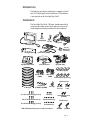
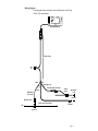
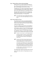
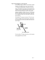
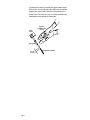
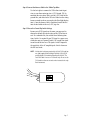
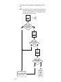
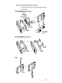
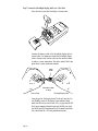
DriveRight
®
VSS Installation Guide
Product # 8155VSS, 8155VF,
8160VSS, 8160VF
Product Number: 8155VSS, 8155VF, 8160VSS, 8160VF
Davis Instruments Part Number: 7395-062
DriveRight VSS Installation Guide
®
Rev. D Manual (7/18/01)
© Davis Instruments Corp. 2001. All rights reserved.
This product complies with the essential protection requirements of
the EC EMC Directive 89/336/EC.
DriveRight is a registered trademark of Davis Instruments Corp.
Velcro is a trademark of Velcro Industries, Manchester NH.
INTRODUCTION
The following instructions explain how to complete a DriveRight VSS (Vehicle Speed Sensor) installation. VSS installation
is only possible on the DriveRight Trip 500AL.
COMPONENTS
The DriveRight Trip 500AL (VSS Input) should come with all
of the materials shown below. Please make sure you have all
listed components before proceeding with the installation.
Battery
(CR123 3V Lithium)
Visor Clip
Harness Cable
DriveRight Display
Mounting Bracket
Right Angle Adapter Bracket
Fuses (2)
(3AG 1-1/4 x 1/4",
.25A, Slo-Blo)
Red +12V Wire
with Fuseholder (22 AWG)
Coiled Cable Extension
Split Flexible Tubing
Velcro® Tape (4 pair)
Black Ground Wire
(22AWG)
White VSS Wire
(22AWG)
Double-Sided Foam Tape (4 strips)
Spade Terminal Sets:
Tie Wraps (12)
Butt Splices (5)
(26-22AWG or 24-20AWG)
In-Line Splice
#6 x 1/2" Pan Head Self-Tapping Screws (3)
6-32 Nuts (3)
6-32 x 1/2" Flat Head Machine Screws (3)
#6 Split Lock Washers (6)
#8-10 Studs
(3.5 - 5 mm)
1/4" Studs
(6 mm)
Insulated Male Disconnects
(18-22AWG)
T-Tap Disconnects:
#6 x 1/2" Flat Head Self-Tapping Screws (3)
#6 Flat Washers (6)
NOTE: Small hardware includes spares not required for installation.
Blue
(14-16AWG)
Red
(18-22AWG)
Page 1
Tools and Materials Needed
The installation requires some or all of the following tools and
materials. Please make sure you have all necessary items before
proceeding with the installation.
❏ Medium Phillips Screwdriver
❏ Crimping Tool
❏ Pliers
❏ Electric Drill with 2.5 mm (7/64") Drill Bit
❏ Fuse Tap
❏ Multimeter
INSTALLATION
The instructions contained in the following sections provide
guidelines for installation of the Trip 500AL.
Planning the Installation
The installation is similar to installing a vehicle stereo or vehicle alarm. The DriveRight requires three electrical inputs;
+12 V, vehicle ground, and your vehicle's VSS signal. The steps
required to install the DriveRight are:
1. Determine where to mount the DriveRight display.
2. Locate and tap your VSS wire.
3. Locate and tap power (+12V from battery) and ground.
4. Connect the harness cable to the 3 main tap wires.
5. Choose the correct switch settings.
6. Mount the DriveRight in the vehicle.
7. Connect the DriveRight and go for a test drive.
WARNING: Installing the DriveRight can be hazardous to both the
installer and your vehicle’s electrical system if not done by
an experienced professional. This manual assumes you are
aware of the inherent dangers of working in and around a
vehicle and have a working understanding of electricity.
Page 2
Wiring Diagram
The diagram below provides an overall picture of the Trip
500AL VSS installation.
DriveRight Display
Harness Cable
White
Red
Butt Splices (3)
Red Wire with Fuseholder
Black
White Wire
(if needed)
In-Line
Splice
Unswitched
+12V
Ground
Male Disconnect
Vehicle Speed Sensor Wire
VSS
Spade
Terminal
T-Tap
Connector
Page 3
Step 1 : Determine Where to Mount the Driveright Display
Knowing where you are going to mount the DriveRight display can help you make wiring decisions later on. For example, if your DriveRight is near the fuse box it will be
convenient to get +12V using a fuse tap connector. However, if
your DriveRight display is on the other side of the vehicle it
may be easier to find a lamp circuit. If the position of the display is not critical, you may wish to move to the next step,
and decide where to mount it after you've tapped the three
main electrical connections (+12V, Ground, VSS).
NOTE: If you need ideas about where the display might be mounted,
look at “Step 6: Mount the DriveRight Display in the Vehicle” on
page 9.
Step 2: Locate and tap your VSS wire
The location of the VSS wire for a given make and model of
vehicle can be found in the Vehicle Technical Information
Guide for Cruise Control book. This book is made available to
authorized DriveRight installers.
If you can not obtain a copy of this book, the information is
available on the World Wide Web at www.rostra.com. Go to
that Web address and click on “Rostra VSS & Tach Information
System". Enter the full year and manufacturer of the vehicle.
The information will specify a “location number” indicating
where the wire can be found, and it will specify the wire color.
NOTE: The web site “www.rostra.com’ is owned and operated by Rostra Precision Instruments. Rostra does not provide support for
the DriveRight product. If you have trouble finding the VSS
wire, please contact Davis Instruments Technical Support at
510-732-7814.
NOTE: Some base model vehicles with manual transmission and no
cruise control may not have the VSS module installed. Also,
vehicles manufactured before 1992 may not have the VSS signal. Consult the service department at your vehicle dealership if
you are having trouble. If your vehicle has a cable driven speedometer, it may be possible for you to purchase a VSS pulse converter that can be installed to provide the VSS pulse. Otherwise,
you will be required to install the Trip 500 AL which uses the
drive shaft-mounted reed switch sensor.
Use the inline splice to make the connection to the VSS wire as
shown below. Select red or blue T-Tap disconnect to fit your
VSS wire.
Page 4
Step 3: Locate and tap power (+12V) and ground
The DriveRight requires a constant +12 volts and has a negligible drain on the vehicle battery (8 ma). You can obtain the
+12V from several different places. Generally, you can easily
obtain +12V from the fuse box using a fuse tap connector (not
supplied) or using the supplied in-line splice connectors to tap
into a KNOWN circuit that does not involve safety related
equipment (headlights, tail lights, air bag, etc.). Possible candidate wires include those from the cigarette lighter, dome light,
glove compartment light, clock, tail gate light, or other convenience functions.
After locating +12V, connect it to the red +12V wire (the one
with the fuse holder) using the in-line splice as shown below.
Do not install the fuse into the fuse holder until instructed to
do so in step 4.
In-Line Splice
Unswitched
+12V
from Vehicle
Trim off flush
stripped wire
Red +12V Wire with Fuseholder
If you are getting +12V from your fuse box, use a fuse tap connector appropriate for your vehicle.
Page 5
A ground can be made by inserting the spade terminal under
the head of a screw threaded into the vehicle chassis and then
crimping the spade terminal onto the black ground wire, as
shown below. Check that the screw is actually grounded using
a multimeter before making the connection.
Vehicle
Ground
Crimp Tool,
22-18 AWG Position
(red dot)
Spade Terminal
3/16 - 1/4"
(5 - 6 mm)
Page 6
Black Ground Wire (22 AWG)
Step 4: Connect the Harness Cable to the 3 Main Tap Wires
Use the butt splice to connect the VSS in-line circuit input
wires to your three main tap wires (+12V, Ground, VSS) by
matching the wire colors. Red is used for +12V, black for the
ground wire, and white for the VSS wire. Make sure the wiring
harness extends to where you can plug the DriveRight display
into it. Once the harness cable is connected, install the fuse
into the fuse holder in the red (+12V) tap wire.
Step 5: Choose the Correct Dip Switch Settings
Because not all VSS signals are the same, you may need to
change the default dip switch setting on the VSS in-line circuit. As a technical note, the switches have following functions. Switch 1 is required if your VSS signal is a square wave
which does not go to ground. Switch 2 AC couples the signal
in and is used for sine wave VSS signals. Switch 3 improves
the sensitivity of the AC coupled signals. Switch 4 turns on
the LED test circuit.
NOTE: No dip switch settings are required for the Ford F-250 truck harness cable supplied with DriveRight Trip500AL VSS #8155VF
and DriveRight VSS Installation/Mounting Kit #8160VF. The
Ford F-250 cable is for use on F-250 trucks only. Do not use the
F-250 cable on other cars or trucks unless instructed to do so by
Davis Instruments.
Page 7
Use this flow chart to determine the optimum dip switch setting.
NOTE: You will need to test drive the vehicle and observe the green test
LED which is enabled using switch 4. 0 (zero) means the switch
is off and 1 means the switch is on. The DriveRIght unit must
be plugged in for the LED to indicate.
Set
1 2 3 4
0 1 0 1
Yes
0 = OFF
1 = ON
Drive 2 mph.
Green LED flashing
or dimmed?
No
Set
1 2 3 4
1 1 0 1
Drive 2 mph.
Green LED flashing
or dimmed?
Yes
No
Set
1 2 3 4
1 0 1 1
Drive 2 mph.
Green LED flashing
or dimmed?
Yes
Turn Test LED Off (SW4)
and you are done.
Page 8
No
VSS not
working.
See
Troubleshooting.
Step 6: Mount the DriveRight Display in the Vehicle
The following illustrations show possible mounting options
for the display.
TOP OF DASHBOARD (Horizontal Surfaces)
Pan Head
Self-Tapping
Screw (2x)
Split-Lock Washer
Flat Washer
OR
Hex Nut
Split-Lock Washer
Flat Washer
Right Angle
Adapter Bracket
Flat Head
Machine
Screw
(2x)
Mounting
Bracket
Loops
Hooks
Velcro on underside
of unit for dashtop
mounting.
FACE OF DASHBOARD (Vertical Surfaces)
OR
Double-Sided
Foam Tape
Flat Head
SelfTapping
Screw
(2x)
Mounting
Bracket
Mounting
Bracket
VISOR
OR
Bumps (3)
Page 9
Step 7: Connect the DriveRight Display and Go for a Test Drive
Insert the battery into the DriveRight as shown below.
Connect the harness cable to the DriveRight display cable as
shown below. It is important to hold the DriveRight display
cable as shown below (on the cable, not the sheath) in order
to achieve a secure connection. The cables should “click” into
place when a secure connection is made.
Plastic
Sheath
Hold cables as shown
to connect.
Harness Cable
DriveRight Display Cable
Once plugged in, the display should “wake-up” into the Current Readings screen. If the display screen remains blank,
make sure the battery is in the unit. If it is, try pressing MODE.
If the screen remains blank after pressing MODE, press both
the MODE and PLUS simultaneously. If it remains blank after
that, check both the +12V and ground connections.
Page 10
Go for a test drive and check that the DriveRight matches the
speedometer. If it is not close at all, do not be discouraged
since it may be uncalibrated. Consult the calibration section
of the Trip 500AL User’s Guide for the Trip 500AL for instructions on calibrating the unit. If after calibrating the unit it still
does not register speed correctly, move on to the troubleshooting section.
It is also possible that the unit may alarm unexpectedly during an initial test drive, which can be caused by incorrect calibration along with the alarm being set or just by the login
alarm being set. Enter a Driver ID code on the unit to silence
the second case. If this does not work, you need to turn the
alarm off. Consult the Trip 500AL’s User’s Guide for specific
instructions on entering a Driver ID code or turning an alarm
off.
NOTE: Remember to turn off the Test LED once the DriveRight is
installed.
APPENDIX 1: TROUBLESHOOTING
If your speed is not regsitering correctly, consult the following
check list to help you identify the cause of the problem.
❏ Make sure the display is reading in the units
(km/hr or mph) you expect.
Hold down the Set/Clr button in the Current
Screen to change the units.
❏ Make sure the unit has been calibrated correctly.
Check the calibration section of the DriveRight display manual.
❏ The switch settings on the VSS in-line circuit
are not correct.
Go back to step 5.
❏ Double check your power and ground connections using a multimeter.
Note that the BAT segment will not be visible
on the display if it is getting +12V.
❏ Make sure the VSS wire is correct.
If the green test LED of the VSS in-line circuit
does not flash at low speeds, you may not
have the correct wire (switch 4 must be on to
Page 11
enable the test circuit). The following other
methods can be used to see if you have the correct wire. In order of preference:
❏ Use a portable oscilloscope and verify the
square wave or sine wave VSS signal.
Watch the signal frequency change with
speed.
❏ Using a multimeter to measure the frequency of the VSS pulse. Usually, the PPM
(pulses per mile) of the VSS signal is
known. At 40 km/hr (25 mph) the following frequencies should be:
2000 PPM : 14 hz
4000 PPM : 28 hz
5000 PPM : 35 hz
8000 PPM : 56 hz
❏ A voltmeter can be used on square wave
signals to verify the 2 DC levels when the
vehicle is moved. Note, in most cases the
vehicle must be running and driven
slowly to detect this change.
❏ Check with your local vehicle dealership to
make sure the vehicle make and model is
equipped with a complete VSS signal.
APPENDIX 2: VSS COMPATIBILITY
The DriveRight can work with many different VSS signals provided the switch settings of the VSS in-line circuit are set correctly. However, if the signal does not meet the specifications
below it may not work.
❏ Maximum VSS frequency at 25 mph is 1 khz
(144,000 PPM).
❏ Minimum peak to peak amplitude at 5 mph is
1 volt.
❏ Maximum peak to peak amplitude is 25 volts.
❏ Input Impedance of VSS inline-circuit is 22k.
Page 12
Technical Support
If you are experiencing problems with your DriveRight VSS,
first be sure to check all cable connections. If you are unable
to solve the problem, please call Davis Technical Support.
We’ll be glad to help. Most questions can be answered while
you’re on the phone. You can also email us for support, or
visit our website. Sorry, we are unable to accept collect calls.
NOTE: Please do not return items to the factory for repair without prior
authorization.
(510) 732-7814 for Technical Support, Monday – Friday, 7:00
a.m. – 5:30 p.m. Pacific Time.
(510) 670-0589 Fax Customer Service or Tech Support.
www.davisnet.com Download copies of user manuals from
the “Support” page. Watch for FAQs and other updates. Subscribe to the e-newsletter.
[email protected] E-mail your technical support questions.
Page 13
3465 Diablo Avenue, Hayward, CA 94545-2778
510-732-9229 • Fax: 510-732-9188
E-mail: [email protected] • www.davisnet.com