1
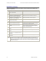
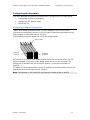
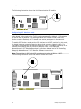
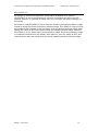
Dialogic® TX 4000 PCI SS7
Network Interface Board
Installation Manual
July 2009
64-0429-01
www.dialogic.com
Copyright and legal notices
Copyright © 2003-2009 Dialogic Corporation. All Rights Reserved. You may not reproduce this document in
whole or in part without permission in writing from Dialogic Corporation at the address provided below.
All contents of this document are furnished for informational use only and are subject to change without notice
and do not represent a commitment on the part of Dialogic Corporation or its subsidiaries (“Dialogic”).
Reasonable effort is made to ensure the accuracy of the information contained in the document. However,
Dialogic does not warrant the accuracy of this information and cannot accept responsibility for errors,
inaccuracies or omissions that may be contained in this document.
INFORMATION IN THIS DOCUMENT IS PROVIDED IN CONNECTION WITH DIALOGIC® PRODUCTS. NO LICENSE,
EXPRESS OR IMPLIED, BY ESTOPPEL OR OTHERWISE, TO ANY INTELLECTUAL PROPERTY RIGHTS IS GRANTED BY
THIS DOCUMENT. EXCEPT AS PROVIDED IN A SIGNED AGREEMENT BETWEEN YOU AND DIALOGIC, DIALOGIC
ASSUMES NO LIABILITY WHATSOEVER, AND DIALOGIC DISCLAIMS ANY EXPRESS OR IMPLIED WARRANTY,
RELATING TO SALE AND/OR USE OF DIALOGIC PRODUCTS INCLUDING LIABILITY OR WARRANTIES RELATING
TO FITNESS FOR A PARTICULAR PURPOSE, MERCHANTABILITY, OR INFRINGEMENT OF ANY INTELLECTUAL
PROPERTY RIGHT OF A THIRD PARTY.
Dialogic products are not intended for use in medical, life saving, life sustaining, critical control or safety systems,
or in nuclear facility applications.
Due to differing national regulations and approval requirements, certain Dialogic products may be suitable for use
only in specific countries, and thus may not function properly in other countries. You are responsible for ensuring
that your use of such products occurs only in the countries where such use is suitable. For information on specific
products, contact Dialogic Corporation at the address indicated below or on the web at www.dialogic.com.
It is possible that the use or implementation of any one of the concepts, applications, or ideas described in this
document, in marketing collateral produced by or on web pages maintained by Dialogic may infringe one or more
patents or other intellectual property rights owned by third parties. Dialogic does not provide any intellectual
property licenses with the sale of Dialogic products other than a license to use such product in accordance with
intellectual property owned or validly licensed by Dialogic and no such licenses are provided except pursuant to a
signed agreement with Dialogic. More detailed information about such intellectual property is available from
Dialogic’s legal department at 9800 Cavendish Blvd., 5th Floor, Montreal, Quebec, Canada H4M 2V9. Dialogic
encourages all users of its products to procure all necessary intellectual property licenses required to implement
any concepts or applications and does not condone or encourage any intellectual property infringement and
disclaims any responsibility related thereto. These intellectual property licenses may differ from country to
country and it is the responsibility of those who develop the concepts or applications to be aware of and comply
with different national license requirements.
Any use case(s) shown and/or described herein represent one or more examples of the various ways, scenarios
or environments in which Dialogic® products can be used. Such use case(s) are non-limiting and do not
represent recommendations of Dialogic as to whether or how to use Dialogic products.
Dialogic, Dialogic Pro, Brooktrout, Diva, Cantata, SnowShore, Eicon, Eicon Networks, NMS Communications, NMS
(stylized), Eiconcard, SIPcontrol, Diva ISDN, TruFax, Exnet, EXS, SwitchKit, N20, Making Innovation Thrive,
Connecting to Growth, Video is the New Voice, Fusion, Vision, PacketMedia, NaturalAccess, NaturalCallControl,
NaturalConference, NaturalFax and Shiva, among others as well as related logos, are either registered
trademarks or trademarks of Dialogic Corporation or its subsidiaries. Dialogic's trademarks may be used publicly
only with permission from Dialogic. Such permission may only be granted by Dialogic’s legal department at 9800
Cavendish Blvd., 5th Floor, Montreal, Quebec, Canada H4M 2V9. Any authorized use of Dialogic's trademarks will
be subject to full respect of the trademark guidelines published by Dialogic from time to time and any use of
Dialogic’s trademarks requires proper acknowledgement.
The names of actual companies and product mentioned herein are the trademarks of their respective owners.
This document discusses one or more open source products, systems and/or releases. Dialogic is not responsible
for your decision to use open source in connection with Dialogic products (including without limitation those
referred to herein), nor is Dialogic responsible for any present or future effects such usage might have, including
without limitation effects on your products, your business, or your intellectual property rights.
Revision history
Revision
Release date
62334-10
November 2003 SRR, SS7 4.0 Beta
Notes
62334-11
April 2004
SRR, SS7 4.0
62334-12
August 2004
SRR. SS7 4.1
62334-13
April 2005
LBG, SS7 4.2
62334-14
July 2008
LBG, SS7 5.0
64-0429-01 July 2009
LBG, SS7 5.1
Last modified: July 7, 2009
Refer to www.dialogic.com for product updates and for information about support policies, warranty
information, and service offerings.
Table Of Contents
Chapter 1: Introduction ..........................................Error! Bookmark not defined.
Chapter 2: Dialogic® TX 4000 PCI SS7 Network Interface Board Installation
Manual...................................................Error! Bookmark not defined.
Chapter 3: Overview of the TX 4000 board ....................................................9
TX 4000 board features................................................................................ 9
Software components .................................................................................11
Utilities and demonstration programs ............................................................12
Chapter 4: Installing the TX 4000 board ......................................................15
System requirements..................................................................................15
Installation summary ..................................................................................16
Configuring the hardware ............................................................................17
Configuring H.100 bus termination .............................................................17
Configuring SS7 Monitor mode ..................................................................18
DIP switch S1 .........................................................................................19
Installing the board ....................................................................................20
Chapter 5: Configuring the TX 4000 board ...................................................21
Using the configuration utility.......................................................................21
Assigning a CP number ...............................................................................22
Adding a board ..........................................................................................23
Changing a CP number................................................................................24
Moving a board ..........................................................................................25
Removing a board ......................................................................................26
Saving configuration changes.......................................................................27
Chapter 6: Establishing network connections ..............................................29
Connectors and cables ................................................................................29
Dialogic® MD1 RJ-45 interface ..................................................................29
Dual T1/E1 120 ohm adapter cable ............................................................30
Ethernet interfaces ..................................................................................30
Connecting to the network...........................................................................31
E1 network considerations ........................................................................32
T1 network considerations ........................................................................32
Testing in loopback mode ............................................................................33
Connecting TX boards for redundancy ...........................................................34
TDM configuration ...................................................................................34
IP network configuration...........................................................................35
Chapter 7: Verifying the installation ............................................................37
External connection status LEDs ...................................................................37
Ethernet LEDs............................................................................................38
Board status LEDs ......................................................................................39
Boot code LEDS.......................................................................................39
Status LEDs ............................................................................................40
Verifying the board installation .....................................................................41
Dialogic Corporation
5
Introduction
TX 4000 PCI SS7 Network Interface Board Installation Manual
Chapter 8: Hardware specifications .............................................................43
General hardware specifications ...................................................................43
Physical .................................................................................................43
Host interface .........................................................................................43
H.100 compliant interface .........................................................................44
Environment ...........................................................................................44
Software environment ..............................................................................44
Power requirements .................................................................................44
Connectivity ...........................................................................................44
CEPT E1 G.703 telephony interface ...............................................................45
DSX-1 telephony interface ...........................................................................45
6
Dialogic Corporation
1
Introduction
The Dialogic® TX 4000 PCI SS7 Network Interface Board Installation Manual explains
how to perform the following tasks:
•
Install the TX 4000 PCI SS7 Network Interface board
•
Configure the TX 4000 PCI SS7 Network Interface board
•
Establish network connections
•
Verify the installation
This manual targets developers of telephony and voice applications who use TX 4000
boards with Dialogic® NaturalAccess™ Signaling Software. This manual defines
telephony terms where applicable, but assumes that the reader is familiar with
telephony concepts, switching, and the C programming language.
Note: The product(s) to which this document pertains is/are among those sold by
NMS Communications Corporation (“NMS”) to Dialogic Corporation (“Dialogic”) in
December 2008. Certain terminology relating to the product(s) has been changed,
whereas other terminology has been retained for consistency and ease of reference.
For the changed terminology relating to the product(s), below is a table indicating
the “New Terminology” and the “Former Terminology”. The respective terminologies
can be equated to each other to the extent that either/both appear within this
document.
Former terminology
Current terminology
NMS SS7
Dialogic® NaturalAccess™ Signaling Software
Natural Access
Dialogic® NaturalAccess™ Software
Dialogic Corporation
7
2
Overview of the TX 4000
board
TX 4000 board features
The Dialogic® TX 4000 PCI SS7 Network Interface board is a PCI board that provides
four T1 or E1 digital trunk interfaces and two Ethernet 10/100Base-T interfaces. The
TX 4000 design is based on an intelligent communication processor (CP) that plugs
into a single PCI bus slot. The CP operates with the PCI bus host processor to form a
distributed communications application platform.
The CP features one high-performance Motorola MPC7457 RISC microprocessor and
one MPC8260 PowerQUICC II controller with a 32-bit PCI bus interface. Dialogic®
NaturalAccess™ Signaling Software packages provide programming capabilities for
the TX 4000 board CP.
Dialogic Corporation
9
Overview of the TX 4000 board
TX 4000 PCI SS7 Network Interface Board Installation Manual
The following illustration shows the TX 4000 board:
Ethernet T1/E1 trunk
connectors connectors
Ethernet
MAC/PHY
chips
T1/E1
status
LEDs
S3 DIP
switch
Framer
Host
bridge
PCI to 60x
bridge
8260
Power
QUICC II
controller
T8100A
H.100
interface
PCI to MPX
bridge
7457 RISC
microprocessor
with fan
H.100 bus
connector
S2 DIP
switch
The TX 4000 board provides:
•
PCI bus connectivity
Each board is designed to reside in a single PCI bus slot. Each board contains a
universal (5.0 V or 3.3 V signaling) PCI bus interface that is compliant with the
PCI Local Bus Specification, Revision 2.2. The PCI interface is a 33/66 MHz, 32bit master/target device.
•
H.100 bus connectivity
The TX 4000 board fully supports the H.100 bus specification. The H.100 bus
enables boards to share data and signaling information with other boards on the
H.100 bus. For example, you can connect two or more TX 4000 boards for
applications that perform trunk-to-trunk switching. In addition, you can use
H.100 compatible products from other manufacturers with the TX 4000 board.
The H.100 interface supports a full mode stream configuration on the H.100 bus
with 32 streams at 8 MHz each. Each stream provides 128 timeslots for a total
of 4096 timeslots.
10
Dialogic Corporation
TX 4000 PCI SS7 Network Interface Board Installation Manual
•
Overview of the TX 4000 board
Telephony bus switching
Switching for the TX 4000 board offers support for the H.100 bus within the
H.100 architecture. On the TX 4000 board, switch connections are allowed for a
total of 256 half duplex or 128 full duplex connections between local devices and
the H.100 bus. Switch connections between local devices are non-blocking.
•
Ethernet connectivity
The TX 4000 board supports two 10/100Base-T Ethernet connections. These
connections provide Fast Ethernet connectivity and IPv4 support. Ethernet
connectivity provides the TX 4000 board with a connection to a redundant mate
TX board or to a network of other SIGTRAN devices.
•
On-board memory
Each TX 4000 board includes 128 MB of SDRAM.
•
Trunk connectivity
The TX 4000 board supports up to four T1 or E1 connectors through two
Dialogic® MD1 RJ-45 interfaces. Dialogic® NaturalAccess™ Signaling Software
enables you to configure the board as either a T1 or an E1 board.
Refer to www.dialogic.com/declarations for a list of countries where Dialogic has
obtained approval for the TX 4000 board.
Software components
TX 4000 boards require the following software components:
•
NaturalAccess software development environment that provides services for
call control, system configuration, voice store and forward, and other
functions. Each service has a standard programming interface for developing
applications. For more information, refer to the Natural Access Developer's
Reference Manual.
•
Dialogic® NaturalAccess™ Signaling Software that provides SS7 protocol
layer executables and program interfaces for developing signaling and
management applications. It also provides utilities that download
configuration information to the TX boards and that control, monitor, and
collect statistics on the SS7 protocol layer. For more information, refer to the
Dialogic® NaturalAccess™ Signaling Software Configuration Manual.
Dialogic Corporation
11
Overview of the TX 4000 board
TX 4000 PCI SS7 Network Interface Board Installation Manual
Utilities and demonstration programs
NaturalAccess Signaling Software provides the following utilities and demonstration
programs for the TX 4000 board. Run these programs from the \Program
Files\Dialogic\tx\bin directory in Windows and from the /opt/dialogic/tx/bin directory
in UNIX. For more information about each utility, refer to the Dialogic® TX Series
SS7 Boards TX Utilities Manual.
Utility
Description
cpcon
Uses NaturalAccess to manage communication with the TX board. This utility is an operator
console run from the command line.
If you want to bypass the NaturalAccess layer, use the cpcon_ utility to monitor the TX
operating system.
cplot
Loads communications processor tasks to TX boards.
cpmodel
Displays the board type for each installed TX board.
pcigetcfg
Obtains bus and slot information during software installation (UNIX only).
txalarm
Uses NaturalAccess to display and optionally log alarm messages generated by NaturalAccess
Signaling Software tasks running on all TX boards.
If you want to bypass the NaturalAccess layer, use the txalarm_ utility to display and
optionally log alarm messages.
txccode
Displays a text description of a completion code (error code) reported by a TX board.
txconfig
Configures TDM and IP based interfaces on TX 4000 boards. ss7load calls txconfig at board
boot time. For more information, refer to the Dialogic® NaturalAccess™ Signaling Software
Configuration Manual.
txcpcfg
Assigns CP numbers to TX boards based on bus and slot.
txdiag
Provides diagnostic information about TX boards.
txdump
Dumps the contents of the shared memory used for communication between the TX board
and the host driver.
txeeprom Displays information stored in the EEPROM.
txflash
Updates the operating system stored in the TX board Flash memory.
txinfo
Obtains detailed TX 4000 board information.
txlocate
Blinks the end bracket LEDs of a TX 4000 board.
txreset
Resets a TX board and reboots the board from the operating system image stored in Flash
memory.
txsnap
Generates a core dump of a TX 4000 board, creating a snapshot file.
txstats
Displays statistics maintained by the TX device driver.
12
Dialogic Corporation
TX 4000 PCI SS7 Network Interface Board Installation Manual
Overview of the TX 4000 board
NaturalAccess™ Signaling Software provides the following programs in compiled and
uncompiled form to demonstrate the usage of the TDM libraries. For information
about these programs, refer to the Dialogic® TX Series SS7 Boards TDM for SS7
Developer's Reference Manual.
Program
Demonstrates how to...
t1demo
Test the T1/E1 and H.100 library functions with TX boards in a system.
t1stat
Receive unsolicited T1/E1 status messages and performance reports.
txdynamic
Dynamically switch SS7 links across TDM channels without rebooting the TX boards.
txsdemo
Use the TX SWI library. Use this program as a starting point to control switching on a TX
4000 board.
Dialogic Corporation
13
3
Installing the TX 4000 board
System requirements
To install and use the TX 4000 board, your system must have the following
components:
•
An available PCI bus slot.
•
At least 8 MB of memory (excluding operating system requirements).
•
NaturalAccess software development environment.
•
NaturalAccess Signaling Software.
•
A chassis with 3.3 V of supplied power to provide a minimum of 6.5 A per TX
4000 board.
•
An uninterruptible power supply (UPS). Although a UPS is not strictly
required, it is strongly recommended for increased system reliability.
•
An H.100 bus connector cable if you are connecting to other H.100 boards.
•
Cables to connect the board interfaces to T1 or E1 lines.
•
A crossover Ethernet cable if you are connecting two TX 4000 boards for
redundancy support.
•
Straight through Ethernet cables if you are connecting to an Ethernet hub or
switch in a SIGTRAN network.
Warning: Important safety notes for telephony connections:
•
Allow only qualified technical personnel to install this board and the associated
telephone wiring.
•
Make sure the PC chassis is grounded through the power cord or by other means before
connecting the telephone line.
•
If your system requires an external power supply, make sure it is grounded through the
power cord or by other means.
•
Never install telephone wiring during a lightning storm.
•
Never install telephone jacks in wet locations.
•
Telephone companies provide primary lightning protection for their telephone lines. If
your site connects to private lines that leave the building, make sure that external
protection is provided.
Dialogic Corporation
15
Installing the TX 4000 board
TX 4000 PCI SS7 Network Interface Board Installation Manual
Installation summary
The following table summarizes the steps for initially installing the hardware and
software components:
Step Description
For details, refer to...
1
Ensure that your system meets the
system requirements.
System requirements on page 15
2
Power down the system if it is running.
3
Configure the TX 4000 board to control
H.100 bus termination if applicable.
Configuring H.100 bus termination on page 17
4
Configure the TX 4000 board to enable
SS7 Monitor mode if applicable.
Configuring SS7 Monitor mode on page 18
5
Install the TX 4000 board into one of the
computer's PCI bus slots.
Installing the board on page 20
6
Power up the system.
7
Install the NaturalAccess software.
The Natural Access Installation booklet and Natural
Access Developer's Reference Manual
8
Install the NaturalAccess Signaling
Software.
Installing Dialogic® NaturalAccess™ Signaling
Software and Dialogic® NaturalAccess™ Signaling
Software Configuration Manual
9
Assign a CP number for each TX 4000
board.
Assigning a CP number on page 22
10
Connect the board interfaces to T1 or E1
trunks.
Connecting to the network on page 31
11
Connect the Ethernet interfaces for board Connecting TX boards for redundancy on page 34
redundancy or to a SIGTRAN network, if
applicable.
12
Verify that the TX 4000 board is
operational.
Verifying the board installation on page 41
Caution: The TX 4000 board is shipped in a protective anti-static container. Leave the board in its
container until you are ready to install it. Handle the board carefully and hold it only by its
edges. We recommend that you wear an anti-static wrist strap connected to a good earth
ground whenever you handle the board. Take care not to touch the gold fingers that plug into
the PCI bus connectors.
16
Dialogic Corporation
TX 4000 PCI SS7 Network Interface Board Installation Manual
Installing the TX 4000 board
Configuring the hardware
This topic describes the following procedures for configuring the TX 4000 board:
•
Configuring H.100 bus termination
•
Configuring SS7 Monitor mode
•
DIP switch S1
Configuring H.100 bus termination
The TX 4000 board connects to an H.100 bus. Boards on the H.100 bus are
connected to one another with an H.100 bus cable. Enable bus termination on the
board located on each end of the H.100 bus.
The following illustration shows the H.100 bus configuration:
H.100 bus cable
Enable bus
termination
Enable bus
termination
DIP switch S2 on the TX 4000 board controls the H.100 bus termination. The DIP
switch is located on the front of the board, below the H.100 bus connector. By
default, all S2 switches are set to the OFF position. H.100 bus termination is
disabled.
To enable H.100 bus termination, set all S2 switches to the ON position only for the
boards that are on the ends of the H.100 bus.
Note: The switches in DIP switch S2 must be set to either all ON or all OFF.
Dialogic Corporation
17
Installing the TX 4000 board
TX 4000 PCI SS7 Network Interface Board Installation Manual
ON
1 2 34 56 7 8
S2
The following illustration shows the H.100 termination DIP switch:
OFF
Configuring SS7 Monitor mode
DIP switch S3 controls the SS7 Monitor mode. The DIP switch is located on the front
of the board, to the right of the T1/E1 trunk connectors. By default, all S3 switches
are set to the ON position. This setting disables SS7 Monitor mode. When SS7
Monitor mode is disabled, the TX board is an active participant in the network.
To enable SS7 Monitor mode, set the S3 switches to the OFF position. In this mode,
the board becomes a passive listening device that monitors network traffic. For
information on connecting the monitoring server (with an installed TX board) to the
network and installing the SS7 Monitor software, refer to the Dialogic®
NaturalAccess™ SS7 Monitor Developer's Reference Manual and to the Installing
Dialogic® NaturalAccess™ SS7 Monitor Software instructions.
Note: The switches in DIP switch S3 must be set to either all ON or all OFF.
ON
18
1 2 3 4
S3
The following illustration shows the Monitor mode DIP switch:
OFF
Dialogic Corporation
TX 4000 PCI SS7 Network Interface Board Installation Manual
Installing the TX 4000 board
DIP switch S1
DIP switch S1 controls the operation of the board. By default, only switch 2
(AUTOSTART) is set to the ON position; all other S1 switches are set to the OFF
position. Switch 5 is reserved for future use. Do not modify the default settings for
this switch.
Set switch 8 (SW MIN BOOT) to ON to boot the board to the original software image
instead of using the current production software image. This allows for recovery from
any condition that resulted in the corruption of the production software image. After
setting this switch to ON, use txreset to boot the backup software image, and then
use txflash to burn a clean copy of the production image. Once the production image
is completely transferred to the board's flash memory, turn this switch to OFF, and
issue txreset to boot the board using the newly loaded production software image.
Dialogic Corporation
19
Installing the TX 4000 board
TX 4000 PCI SS7 Network Interface Board Installation Manual
Installing the board
Complete the following steps to install the TX 4000 board in your system:
Step
Action
1
If necessary, configure the board as described in Configuring the hardware on page 17.
2
Power down the computer and disconnect the power cord from the power source.
3
Remove the cover from the computer and set it aside.
4
If you are placing the board into a PCI chassis, remove the PCI retainer bracket by unscrewing it
from the board. The bracket is not needed for the board to properly fit into the chassis. Refer to
the following illustration of the PCI retainer bracket:
PCI retainer bracket
(2.2 compliant)
Retainer screws
If you are placing the board into an ISA chassis, leave the PCI retainer bracket attached to the
board. The bracket is needed for the board to fit properly into the chassis.
5
Remove the blank slot cover from an open PCI bus slot.
6
Arrange the TX 4000 board and other H.100 boards in adjacent PCI bus slots.
Insert the TX 4000 board firmly into the slot. Ensure that the gold-striped edge of the board is
seated properly in the expansion slot groove and the bracket of the board is seated in the
groove that previously held the slot cover.
7
Align the top of the board bracket with the hole on the top of the expansion slot, and replace
the screw that previously held the blank slot cover.
8
Connect the H.100 bus cable to the TX 4000 board.
If you have multiple H.100 boards, connect the H.100 bus cable to each H.100 board.
9
20
Replace the cover, and connect the computer to the power source.
Dialogic Corporation
4
Configuring the TX 4000 board
Using the configuration utility
After you install the TX 4000 board and the NaturalAccess Signaling Software, you
must assign a CP number to each TX 4000 board. Verify that you have completed
the steps described in the installation summary on page 16 before you proceed to
assigning a CP number on page 22.
To assign a CP number, you will use the txcpcfg utility. Depending on the operating
environment, the txcpcfg utility is located in one of the following directories:
Operating system
Directory
Windows
Program Files\Dialogic\tx\bin\
UNIX
/opt/dialogic/tx/bin/
txcpcfg enables you to perform the following types of changes to the configuration:
•
Assign a CP number
•
Add a board
•
Change a CP number
•
Move a board
•
Remove a board
•
Save configuration changes
For more information about txcpcfg, refer to the Dialogic® TX Series SS7 Boards TX
Utilities Manual.
Dialogic Corporation
21
Configuring the TX 4000 board
TX 4000 PCI SS7 Network Interface Board Installation Manual
Assigning a CP number
Complete the following steps to assign a CP number to an installed TX board:
Step
Action
1
Power up the system if it is not running.
In a Windows system, the Windows® New Hardware Wizard appears and prompts you for the
files required to activate the SS7 drivers. Refer to Installing Dialogic® NaturalAccess™ Signaling
Software for detailed information.
2
At the prompt, invoke txcpcfg by entering the following command:
txcpcfg
txcpcfg displays the bus number, slot number, CP number, and CP model of boards that are
present and configured. Only the bus number, slot number, and CP model type identify the
board that you are currently configuring. The CP number is undefined. For example:
Bus
2
2
2
Slot
2
4
6
CP Number
1
2
UNDEFINED
CP
TX
TX
TX
Model
4000
4000
4000
3
Record the bus and slot values for the undefined TX 4000 board.
4
Assign a unique CP number to each undefined board by entering the following command:
txcpcfg
bus
slot
unique_CP_number
where
•
bus is the bus number of the TX 4000 board that you are configuring.
•
slot is the slot number of the TX 4000 board that you are configuring.
•
unique_CP_number is a number you assign. Valid CP numbers within the system start at
1 and must be unique. They do not have to be consecutive.
For example, enter the following command to assign a CP number of 3 for the board with a bus
number of 2 and a slot number of 6:
txcpcfg
5
2
6
3
Verify the configuration of all of the TX boards by entering the following command:
txcpcfg
In this example if you assign the new board a unique CP number of 3, the following
configuration information is displayed:
Bus
2
2
2
Slot
2
4
6
CP Number
1
2
3
CP
TX
TX
TX
Model
4000
4000
xxxx
where xxxx is 4000 for a TX 4000/C, TX 4000/20, or TX 4000/20C board.
6
Save the configuration changes.
In a Windows system, configuration changes are saved automatically. In a UNIX system,
configuration changes are deleted when you restart the system. Save the changes by editing the
cpcfg file as described in Saving configuration changes on page 27.
22
Dialogic Corporation
TX 4000 PCI SS7 Network Interface Board Installation Manual
Configuring the TX 4000 board
Adding a board
Complete the following steps to add a new undefined TX 4000 board:
Step
Action
1
Power down the system if it is running.
2
Insert the TX 4000 board, seating it firmly in an available slot.
3
Power up the system.
If you are installing a TX 4000 board in a Windows system for the first time, the Windows® New
Hardware Wizard appears and prompts you for the files required to activate the SS7 drivers. For
more information, refer to Installing Dialogic® NaturalAccess™ Signaling Software.
If you are installing an additional TX 4000 board in a slot that has never held a TX 4000 board,
the Windows® New Hardware Wizard appears, finds the required files, and exits.
4
At the prompt, invoke txcpcfg by entering the following command:
txcpcfg
txcpcfg displays the bus number, slot number, CP number, and CP model of boards that are
present and configured. Only the bus number, slot number, and CP model type identify the
board that you are currently adding. The CP number is undefined. For example:
Bus
2
2
2
Slot
2
4
6
CP Number
1
2
UNDEFINED
CP
TX
TX
TX
Model
4000
4000
4000
5
Record the bus and slot values for the new undefined TX 4000 board.
6
Assign a unique CP number to each undefined board by entering the following command:
txcpcfg
bus
slot
unique_CP_number
where
•
bus is the bus number of the TX 4000 board that you are configuring.
•
slot is the slot number of the TX 4000 board that you are configuring.
•
unique_CP_number is a number you assign. Valid CP numbers within the system start at
1 and must be unique. They do not have to be consecutive.
For example, enter the following command to assign a CP number of 3 for the board with a bus
number of 2 and a slot number of 6:
txcpcfg
7
2
6
3
Verify the configuration of all of the TX boards by entering the following command:
txcpcfg
In this example, if you assign the new board a unique CP number of 3, the following
configuration information displays:
Bus
2
2
2
Slot
2
4
6
CP Number
1
2
3
CP
TX
TX
TX
Model
4000
4000
xxxx
where xxxx is 4000 for a TX 4000/C, TX 4000/20, or TX 4000/20C board.
8
Save the configuration changes.
In a Windows system, configuration changes are saved automatically. In a UNIX system,
configuration changes are deleted when you restart the system. Save the changes by editing the
cpcfg file as described in Saving configuration changes on page 27.
Dialogic Corporation
23
Configuring the TX 4000 board
TX 4000 PCI SS7 Network Interface Board Installation Manual
Changing a CP number
Complete the following steps to change the CP number of a TX board:
Step
Action
1
At the prompt, invoke txcpcfg by entering the following command:
txcpcfg
txcpcfg displays the bus number, slot number, CP number, and CP model of all the TX boards
that are present and configured.
Bus
2
2
2
Slot
2
4
6
CP Number
1
2
3
CP
TX
TX
TX
Model
4000
4000
xxxx
where xxxx is 4000 for a TX 4000 board.
2
Record the bus and slot values for the TX 4000 board that you are updating.
3
Change the CP number of a board by entering the following command with the updated CP
number:
txcpcfg
bus
slot
updated_CP_number
where
•
bus is the bus number of the TX 4000 board that you are configuring.
•
slot is the slot number of the TX 4000 board that you are configuring.
•
unique_CP_number is a number you assign. Valid CP numbers within the system start at
1 and must be unique. They do not have to be consecutive.
For example, enter the following command to change a CP number of 3 to a CP number of 4 for
the board with a bus number of 2 and a slot number of 6:
txcpcfg
4
2
6
4
Verify the configuration change by entering the following command:
txcpcfg
txcpcfg displays configuration information for the board. The following example indicates a CP
number of 4 for the TX board with a bus number of 2 and a slot number of 6:
Bus
2
2
2
Slot
2
4
6
CP Number
1
2
4
CP
TX
TX
TX
Model
4000
4000
xxxx
where xxxx is 4000 for a TX 4000/C, TX 4000/20, or TX 4000/20C board.
5
Save the configuration changes.
In a Windows system, configuration changes are saved automatically. In a UNIX system,
configuration changes are deleted when you restart the system. Save the changes by editing the
cpcfg file as described in Saving configuration changes on page 27.
24
Dialogic Corporation
TX 4000 PCI SS7 Network Interface Board Installation Manual
Configuring the TX 4000 board
Moving a board
Complete the following steps to move a TX board from one slot to another slot:
Step
Action
1
Power down the system if it is running.
2
Move the TX 4000 board from one slot to another slot, seating it firmly in the new slot.
3
Power up the system.
In a Windows system, if you are installing a TX 4000 board in a slot that has never held a TX
4000 board, the Windows® New Hardware Wizard appears, finds the required files, and exits.
4
At the prompt, invoke txcpcfg by entering the following command:
txcpcfg
txcpcfg displays the bus number, slot number, CP number, and CP model of boards that are
present and configured. Only the bus number, slot number, and CP model type identify the
board that you are currently configuring. The CP number is undefined. For example:
Bus
2
2
2
Slot
2
4
8
CP Number
1
2
UNDEFINED
CP
TX
TX
TX
Model
4000
4000
4000
5
Record the bus and slot values for the TX 4000 board that you moved.
6
Assign a unique CP number to the undefined board by entering the following command:
txcpcfg
bus
slot
unique_CP_number
where
•
bus is the bus number of the TX 4000 board that you are configuring.
•
slot is the slot number of the TX 4000 board that you are configuring.
•
unique_CP_number is a number you assign. Valid CP numbers within the system start at
1 and must be unique. They do not have to be consecutive.
For example, enter the following command to assign a CP number of 3 for the board with a bus
number of 2 and a slot number of 8:
txcpcfg
7
2
8
3
Verify the configuration change by entering the following command:
txcpcfg
txcpcfg displays configuration information. The following example indicates a CP number of 3 for
the TX board with a bus number of 2 and a slot number of 8:
Bus
2
2
2
Slot
2
4
8
CP Number
1
2
3
CP
TX
TX
TX
Model
4000
4000
xxxx
where xxxx is 4000 for a TX 4000, TX 4000/20, TX 4000C, or TX 4000/20C board.
8
Save the configuration changes.
In a Windows system, configuration changes are saved automatically. In a UNIX system,
configuration changes are deleted when you restart the system. Save the changes by editing the
cpcfg file as described in Saving configuration changes on page 27.
Dialogic Corporation
25
Configuring the TX 4000 board
TX 4000 PCI SS7 Network Interface Board Installation Manual
Removing a board
Complete the following steps to remove a TX board from the system:
Step
Action
1
Power down the system if it is running.
2
Remove the TX 4000 board from the slot.
3
Power up the system.
4
Verify the configuration change by entering the following command:
txcpcfg
For example, if you remove a TX board with a CP number of 2, no configuration information for
the removed board is displayed, as in the following example:
Bus
2
2
5
Slot
2
8
CP Number
1
3
CP Model
TX 4000
TX 4000
Save the configuration changes.
In a Windows system, configuration changes are saved automatically. In a UNIX system,
configuration changes are deleted when you restart the system. Save the changes by editing the
cpcfg file as described in Saving configuration changes on page 27.
26
Dialogic Corporation
TX 4000 PCI SS7 Network Interface Board Installation Manual
Configuring the TX 4000 board
Saving configuration changes
In a Windows system, any changes that you make to the configuration information
with the txcpcfg utility are saved automatically.
In a UNIX system, changes that you make to the configuration information with the
txcpcfg utility are deleted when you restart the system. Save the changes by editing
the cpcfg file as described in the following procedure:
Step
Action
1
At the prompt in the UNIX system, view the current configuration updates by entering the
following command:
txcpcfg
txcpcfg displays the bus number, slot number, CP number, and CP model type of each TX board
in the system. For example:
Bus
2
2
2
Slot
2
8
CP Number
1
3
CP Model
TX 4000
TX 4000
Using a text editor, open the cpcfg configuration file. The file contains the original configuration
information that existed before you ran the txcpcfg utility and made changes. For example:
# Command
txcpcfg
txcpcfg
Bus
2
2
Slot
2
8
CP Number
1
2
Note: The cpcfg file does not specify the CP model type. The model type is automatically
determined each time the host operating system is booted.
3
Following the cpcfg file format, edit the entry in the cpcfg file for the TX board CP number that
you are updating. If you are adding a new board, add a new txcpcfg entry to the cpcfg file.
Continuing with the example in step 1, the board with a CP number of 2 is updated to reflect the
new CP number of 3.
# Command
txcpcfg
txcpcfg
4
Bus
2
2
Slot
2
8
CP Number
1
3
Save and close the cpcfg file.
The cpcfg script executes as part of the boot process and applies the new configuration settings.
Dialogic Corporation
27
5
Establishing network
connections
Connectors and cables
The TX 4000 board has two Dialogic® MD1 RJ-45 T1/E1 trunk interfaces and two
Ethernet connectors. The following illustration shows these connectors on the TX
4000 end bracket:
Trunk 1
(and Trunk 3 if applicable)
Trunk 2
(and Trunk 4 if applicable)
Ethernet 1
Ethernet 2
Dialogic® MD1 RJ-45 interface
The TX 4000 provides an Dialogic® MD1 RJ-45 interface to connect to a T1 or E1
network. The following illustration shows the Dialogic® MD1 RJ-45 pinouts:
Pin 1
Pin 8
Pin
Pin
Pin
Pin
Pin
Pin
Pin
Pin
1:
2:
3:
4:
5:
6:
7:
8:
(Port
(Port
(Port
(Port
(Port
(Port
(Port
(Port
1)
1)
2)
1)
1)
2)
2)
2)
R - Receive from
T - Receive from
T1 - Transmit to
R1 - Transmit to
T1 - Transmit to
R1 - Transmit to
T - Receive from
R - Receive from
network
network
network
network
network
network
network
network
To access Trunk 1, Trunk 2, or both Trunks 1 and 2, connect a shielded T1 or E1 RJ45 cable to one or both 8-pin modular jacks on the board.
To access all four trunks, use two dual T1/E1 120 ohm trunk adapter cables. Each
trunk adapter cable separates the 8-pin modular jack on the board into two RJ-48C
interfaces.
Dialogic Corporation
29
Establishing network connections
TX 4000 PCI SS7 Network Interface Board Installation Manual
Dual T1/E1 120 ohm adapter cable
The following illustration shows a dual T1/E1 120 ohm trunk adapter cable:
B
Dialogic® MD1
RJ-45
A
RJ-48C
Length: 4 “
The following illustration shows the pinouts of the RJ-48C connectors on the trunk
adapter cable:
Pin 1
Pin 8
Pin
Pin
Pin
Pin
Pin
Pin
Pin
Pin
1:
2:
3:
4:
5:
6:
7:
8:
R - Receive from network
T - Receive from network
No connection
R1 - Transmit to network
T1 - Transmit to network
No connection
Optional shield, not used
Optional shield, not used
For more information about the trunk connections, refer to the Dialogic®
NaturalAccess™ Signaling Software Configuration Manual.
Note: The TX 4000 board is configured as a T1/E1 120 ohm board. To connect the
TX 4000 board to a 75-ohm E1 trunk, use a balun. A balun is a transformer that
converts the impedance from 120 ohm to 75 ohm. No other configuration changes
are required. For more information, contact a Dialogic Services and Support
representative.
Ethernet interfaces
The TX 4000 board has two 10/100Base-T Ethernet interfaces. These interfaces
provide Ethernet connections that support auto-negotiation for 100Base-T full
duplex/half duplex and 10Base-T full duplex/half duplex transmission. Each Ethernet
interface can be manually configured if you are not using auto-negotiation.
The Ethernet interfaces provide a high-speed interface for connecting a TX 4000
board to either its redundant mate board or to a network of other SIGTRAN devices.
Refer to Connecting TX boards for redundancy on page 34 for more information.
The following illustration shows the pinouts of the 10/100Base-T Ethernet RJ-45
interfaces:
LINK/ACT LED
Pin 1
Pin 8
Pin
Pin
Pin
Pin
Pin
Pin
Pin
Pin
1:
2:
3:
4:
5:
6:
7:
8:
T - Transmit
R - Transmit
T1 - Receive
Ground
Ground
R1 - Receive
Ground
Ground
to network
to network
from network
from network
100 LED
30
Dialogic Corporation
TX 4000 PCI SS7 Network Interface Board Installation Manual
Establishing network connections
Connecting to the network
Before connecting a TX 4000 board to the network, ensure that you have properly
configured the trunks as either T1 or E1. For configuration information, refer to the
Dialogic® NaturalAccess™ Signaling Software Configuration Manual.
Caution: Dialogic obtains board-level approval certificates for supported countries. Some countries
require that you obtain system-level approvals for boards connected to the public network.
To learn what approvals you require, contact the appropriate regulatory authority in the
target country.
Use a shielded RJ-45 cable to connect a TX 4000 board to a T1 network or to an E1120 ohm network. Complete the following steps to connect a TX 4000 board to the
network:
Step
Action
1
If connecting Trunk 1 or Trunk 2, connect a shielded RJ-45 cable directly to the board.
If connecting Trunk 3 or Trunk 4, use dual T1/E1 120 ohm trunk adapter cables to connect to
the board. Each trunk adapter cable divides the 8-pin modular jack on the end bracket into two
RJ-48C connectors. If you are connecting both jacks, use two cables, otherwise, just use one.
Note: TX 4000 boards are configured as T1/E1 120 ohm boards. To connect a TX 4000 board as
an E1 75 ohm board, use a balun transformer to convert the impedance from 120 ohm to 75
ohm. No other configuration changes are required. For more information, contact a Dialogic
Services and Support representative.
2
Connect shielded RJ-45 cables directly to the trunk connector on the board or to the dual T1/E1
trunk adapter cable.
Caution:
Failure to use a shielded cable may negate your approval.
The following illustration shows the cabling required to connect all four trunks on the
TX 4000 board:
Dual T1/E1 120 ohm
adapter cables
Trunks 1 and 3
Trunks 2 and 4
Ethernet 1
Shielded RJ-45 cables
Ethernet 2
TX 4000 board
For more information, refer to dual T1/E1 120 ohm adapter cable on page 30.
Dialogic Corporation
31
Establishing network connections
TX 4000 PCI SS7 Network Interface Board Installation Manual
E1 network considerations
TX 4000 boards can support up to four CEPT E1 trunk interfaces. For typical E1
communications, each E1 interface connects directly to an E1 trunk, as shown in the
following illustration:
TX 4000
Public service
telephone network
or proprietary
network
E1 trunk
Note: Trunks do not synchronize until the board is booted with a valid E1
configuration.
T1 network considerations
For typical T1 communications, each trunk interface connects to a channel service
unit (CSU), which is connected to a T1 trunk line. The CSU provides a DSX-1
interface to the T1 line, and also contains circuitry that enables the central office
(CO) to perform diagnostic tests remotely. The following illustration shows the TX
4000 trunk interface with CSU:
TX 4000
DSX-1
interface
T1
CSU
trunk
Public service
telephone network
Note: Trunks do not synchronize until the board is booted with a valid T1
configuration.
You can purchase or lease the CSU from the telephone company or other vendor.
Warning: Important safety notes for telephony connections:
Use a channel service unit (CSU) to isolate the cables that are attached to this product
before the cables leave the building.
To avoid causing T1 service provider alarms, make sure that the board always sends
a valid signal, either by looping back at the CSU or by connecting the CSU to a
functioning TX 4000 board. The best way to provide a loopback is to unplug the cable
from the TX board to the CSU. The modular connector on most CSUs loops back the
transmit signal to the receive signal when nothing is plugged in.
32
Dialogic Corporation
TX 4000 PCI SS7 Network Interface Board Installation Manual
Establishing network connections
Testing in loopback mode
You can connect the board in loopback mode to test the digital trunk application
without connecting to the telephone network. The following illustration shows the
loopback configuration that connects trunk 1 and trunk 2 with crossover cable on a
TX 4000 board:
Trunks 1 and 3
Crossover cable
Trunks 2 and 4
1
2
4
5
1
2
4
5
Wiring diagram of crossover cable
The crossover cable connects the transmit signals from one trunk to the receive
signals on another trunk by connecting the pins as shown.
If your board configuration uses two optional trunk adapter cables to access trunks 3
and 4, you can connect the adapter cables in loopback mode. Use the crossover
cable to connect the transmit signals on one of the adapter cables to the receive
signals on the second adapter cable as shown in the following illustration:
Dual T1/E1 120 ohm
adapter cables
Trunks 1 and 3
Trunks 2 and 4
Shielded RJ-45 cables
Ethernet 1
Ethernet 2
TX 4000 board
Dialogic Corporation
33
Establishing network connections
TX 4000 PCI SS7 Network Interface Board Installation Manual
Connecting TX boards for redundancy
Use the redundancy feature to enable the system to detect and recover from the
failure of signaling links on a TX 4000 board, the failure of a signaling node, or the
failure of the TX 4000 board itself.
In a redundant configuration, each pair of TX boards is connected through a private
Ethernet connection. If other devices are connected to the private Ethernet link,
avoid overloading the link. Packets can be lost between the redundant TX boards if
the connection is overloaded.
This topic describes dual-node redundant signaling and single-node redundant
signaling for the following types of configurations:
•
TDM configuration
•
IP network configuration
TDM configuration
To connect a TX 4000 board to its redundant mate in a TDM configuration, use a
Category 5 shielded twisted pair (STP) crossover cable. With the crossover cable,
connect Ethernet 1 on the primary board to Ethernet 1 on the backup board.
You must specify the IP address of the TX board’s redundant mate using the mate
command in the txconfig utility. You must also define the IP interface address using
the ifcreate command (for interface 1) in the txconfig utility. For more information,
refer to the Dialogic® NaturalAccess™ Signaling Software Configuration Manual.
Dual-node redundant signaling server
The following illustration shows how to set up two TX 4000 boards based on a dualnode redundant signaling server in a TDM configuration. The boards are located in
two separate chassis to ensure board-level and system-level redundancy.
SS7 links
Chassis 1
with TX 4000
(primary)
Ethernet 1
Chassis 2
with TX 4000
(backup)
Ethernet 1
Private Ethernet connection
34
Dialogic Corporation
TX 4000 PCI SS7 Network Interface Board Installation Manual
Establishing network connections
Single-node redundant signaling server
The following illustration shows how to set up two TX 4000 boards based on the
single-node signaling server in a TDM configuration. The boards are located in the
same chassis to ensure board-level redundancy.
SS7 links
TX 4000
(primary)
Chassis 1
Ethernet 1
TX 4000
(backup)
Ethernet 1
Private Ethernet connection
IP network configuration
To connect a TX 4000 board to its redundant mate in an IP network configuration,
use a Category 5 shielded twisted pair (STP) crossover cable. Using the crossover
cable, connect Ethernet 1 on the primary board to Ethernet 1 on the backup board.
Using standard Ethernet cables, connect the Ethernet 2 connectors on both boards to
the IP network connectors.
Note: Dialogic recommends using a private Ethernet link to connect the redundant
boards to avoid loss or delay of vital checkpoint messages. However, if each board in
the redundant pair requires multi-homing, you can use Ethernet 1 for both the
redundant pathway and for SIGTRAN network access. In this configuration, the
Ethernet 1 on each board is connected to what is shown as an IP network cloud in
the illustrations that follow (just as the Ethernet 2 connectors are). Be aware that
this greatly increases the chance of lost or delayed checkpoint messages which can
result in the backup having outdated information.
You must specify the IP address of the TX board’s redundant mate using the mate
command in the txconfig utility. You must also define the IP interface address using
the ifcreate command (for interface 1) in the txconfig utility. For more information,
refer to the Dialogic® NaturalAccess™ Signaling Software Configuration Manual.
Dialogic Corporation
35
Establishing network connections
TX 4000 PCI SS7 Network Interface Board Installation Manual
Dual-node redundant signaling server
The following illustration shows how to set up two TX 4000 boards based on a dualnode redundant signaling server in an IP network configuration. The boards are
located in two separate chassis to ensure board-level and system-level redundancy.
Single-node redundant signaling server
The following illustration shows how to set up two TX 4000 boards based on a singlenode signaling server in an IP network configuration. The boards are located in the
same chassis to ensure board-level redundancy.
For more information on SS7 redundancy, refer to the Dialogic® TX Series SS7
Boards Health Management Developer's Reference Manual.
36
Dialogic Corporation
6
Verifying the installation
External connection status LEDs
The TX 4000 board provides LEDs to indicate the status of the trunk interfaces. The
location of the LEDs is shown in the following illustration:
Green status LEDs
Trunks
1 2
3
4
Trunk 1
(and Trunk 3 if applicable)
Trunk 2
(and Trunk 4 if applicable)
The TX 4000 board end bracket has one green LED for each trunk. The trunk LEDs
provide the following indications:
LED
Description
Off
Trunk has not been configured.
Slow blinking
green
Indicates loss of signal.
Fast blinking
green
Indicates loss of frame or loss of signaling multiframe.
Steady green
Indicates that proper frame synchronization between the trunk and network has been
established. All required framing alignment has been found.
Dialogic Corporation
37
Verifying the installation
TX 4000 PCI SS7 Network Interface Board Installation Manual
Ethernet LEDs
The TX 4000 board provides two LEDs to indicate the status of each Ethernet
interface. The LEDs are located in the RJ-45 connectors as shown in the following
illustration:
Ethernet 1 LINK/ACT LED (green)
Ethernet 1 100 LED (green)
Ethernet 2 LINK/ACT LED (green)
Ethernet 2 100 LED (green)
The following table describes the functionality of each LED:
LED
Description
LINK/ACT Indicates the status of the Ethernet link. When the Ethernet link has established link
integrity, the LED is on and steady. It also indicates the transmitting and receiving activity
on the link. When activity is present on the Ethernet link, the LED flickers.
100
38
Indicates the data rate of the Ethernet link. When the LED is on, the data rate is 100 Mb.
When the LED is off, the data rate is 10 Mb. The LED is used only when a reliable Ethernet
connection has been established. (The LINK/ACT LED is on.)
Dialogic Corporation
TX 4000 PCI SS7 Network Interface Board Installation Manual
Verifying the installation
Board status LEDs
In addition to external connection status LEDs and Ethernet LEDs, the following
banks of LEDs (D6-D21) located on the back of the TX 4000 board indicate the
current status of the board:
•
Boot code LEDs
•
Status LEDs
The following illustration shows the TX 4000 board status LEDs:
Status LEDs
Boot code LEDs
D9
D8
D13
D12
D19
D18
D21
D20
D7
D11
D15
D17
D6
D10
D14
D16
Boot code LEDS
The boot code LEDs are active when the TX 4000 board is powered up. These LEDs
progress through a series of red codes. If the power up is successful, these LEDs
turn green.
If no LEDs illuminate, the voltage levels may be too low, or the power supply may
not be providing enough 3.3 V or 5 V of current to power up the TX 4000 board.
Dialogic Corporation
39
Verifying the installation
TX 4000 PCI SS7 Network Interface Board Installation Manual
Status LEDs
After the boot code LEDs become green, the status LEDs are active and indicate the
current board status as described in the following table:
LED
number
Color
D8
Green Timer interrupt controlled heartbeat. The LED flickers to show that the timer
interrupts are operating properly.
D9
Green Idle task controlled heartbeat. The LED flickers to show that the on-board operating
system is operational.
D12
Red
The board is executing in snapshot mode: the board is resetting or txsnap is
running.
D13
------
Reserved for internal use.
D18
Red
The kernel detected a host communication error.
D19
Red
A memory full condition occurred on the board.
D20
Red
An unexpected exception occurred on the board.
D21
Red
The kernel detected a problem. Use the cpcon utility's log command to view logged
error information. For information about using cpcon, refer to the Dialogic® TX
Series SS7 Boards TX Utilities Manual.
40
Status when illuminated
Dialogic Corporation
TX 4000 PCI SS7 Network Interface Board Installation Manual
Verifying the installation
Verifying the board installation
Complete the following steps to verify that each board is successfully installed:
Step
Action
1
Display a list of all of the TX boards detected in the system by entering the following command:
txcpcfg
txcpcfg displays the bus number, slot number, CP number, and CP model type of each detected
TX board. For example:
Bus
5
5
Slot
7
8
CP Number
1
2
CP Model
TX 4000
TX 4000
If the CP number is listed as undefined, assign a CP number. For more information, refer to
Assigning a CP number on page 22.
2
Ensure that each installed and configured board in the system appears in the list of boards.
3
Display a list by CP number and board type of all the TX boards in the system by entering the
following command at the prompt:
cpmodel
cpmodel displays each TX board by model type and assigned CP number. For example:
Board #1 is a TX 4000
Board #2 is a TX 4000
4
Ensure that the boards listed by the txcpcfg utility in Step 1 are the same boards listed by the
cpmodel utility in step 3.
5
Perform board-level diagnostic tests on each new board to verify the installation by entering the
following command at the prompt:
txdiag
-b
boardnum
where boardnum is the CP number of the board.
txdiag indicates the successful installation of the CP 1 board.
TXDIAG V2.0: (c)Copyright 1998-2009 Dialogic Corporation.
CP 1: NMI - Resetting...
CP 1: NMI - ...Reset Complete
CP 1: NMI - Starting test...
CP 1: NMI - SUCCESS CP 1: MEMSWEEP - Resetting...
CP 1: MEMSWEEP - ...Reset Complete
CP 1: MEMSWEEP - Starting test...
CP 1: MEMSWEEP - SUCCESSCP 1: INTR - Resetting...
CP 1: INTR - ...Reset Complete
CP 1: INTR - Starting test...
CP 1: TXDIAG - Resetting...
CP 1: TXDIAG - ...Reset Complete
All Rights Reserved.
Refer to the Dialogic® TX Series SS7 Boards TX Utilities Manual for detailed
information about txcpcfg, cpmodel, and txdiag.
Dialogic Corporation
41
7
Hardware specifications
General hardware specifications
This topic describes the following types of hardware specifications:
•
Physical
•
Host interface
•
H.100 compliant interface
•
Environment
•
Software environment
•
Power requirements
•
Connectivity
Physical
Feature
Specification
Form factor
Standard length PCI board
PCI bus
33/66 MHz, 32-bit master/target or slave 5.0 V or 3.3 V signaling compatible slot
Input/output
PCI end bracket
Board weight 0.40 lb (0.20 kg)
Host interface
Feature
Specification
Electrical
PCI bus designed to PCI Local Bus Specification Revision 2.2
Mechanical
Designed to PCI Local Bus Specification Revision 2.2
Bus speed
DC to 66 MHz
Maximum number of boards per chassis
16
Maximum number of SS7 links per board 32 per TX 4000 board
16 per TX 4000/20 board
I/O mapped memory
Memory mapped interface for efficient block data transfers
Plug and play
Compatible (Windows only)
Dialogic Corporation
43
Hardware specifications
TX 4000 PCI SS7 Network Interface Board Installation Manual
H.100 compliant interface
H.100 compliant interface has the following features:
•
Flexible connectivity between T1 and E1 trunks and the H.100 bus
•
Access to any of 4096 H.100 timeslots
•
Compatible with any H.100 compliant telephony interface
•
H.100 clock master or clock slave
•
H.100 bus termination capability
Environment
Feature
Description
Operating temperature 0 to 50 °C
Storage temperature
-20 to 70 °C
Humidity
5% to 80%, non-condensing
Software environment
Feature
Description
Development environment NaturalAccess Software
Operating system
Windows
UNIX
Power requirements
State
Requirements
TX 4000 0.1 A maximum @ 12.0 V
0.5 A maximum @ 5.0 V
6.5 A maximum @ 3.3 V
Connectivity
Feature
Description
Ethernet
connectivity
Two 10/100Base-T Ethernet interface with RJ-45 connectors for connecting to either
a network of other SIGTRAN devices or for connecting to a redundant mate board.
PSTN network
connectivity
Two T1/E1 Dialogic® MD1 RJ-45 interfaces
Intra-chassis
connectivity
H.100 bus. Lucent Ambassador T8100A with 256 half duplex or 128 full duplex
timeslots
44
Dialogic Corporation
TX 4000 PCI SS7 Network Interface Board Installation Manual
Hardware specifications
CEPT E1 G.703 telephony interface
Feature
Specification
Interface
G.703 2048 kbit/s trunk interface
Line code
HDB3 (in zero code suppression) or AMI
Alarm signal
capabilities
Loss of frame alignment, out of frame conditions, loss of signaling multiframe
alignment and loss of CRC multiframe alignment (red), remote alarm and remote
multiframe alarm (yellow), alarm indication signal (AIS)
Counts
Bit error rate, CRC errors, slips, line code violations, far-end block errors
Loopback
Per channel and across channels under software control
Connectors
Two Dialogic® MD1 RJ-45 interfaces that can support up to four 120 ohm RJ-48C trunk
connectors (using two dual T1/E1 trunk adapter cables).
DSX-1 telephony interface
Feature
Specification
Interface
ANSI T1.102, T1.403
Framing
D4, ESF
Line code
AMI
Zero bits
Selectable B8ZS, jammed bit (ZCS) or no zero code suppression
Alarm signal
capabilities
Yellow and red
Counts
Bipolar violation, F(t) error, and CRC error
Loopback
Per channel and overall under software control. Automatic remote loopback with
CSU option.
Connectors
Two Dialogic® MD1 RJ-45 interfaces that can support up to four 120 ohm RJ-48C
trunk connectors (using two dual T1/E1 trunk adapter cables).
Maximum cable
length
655 feet of 22 AWG twisted pair
Dialogic Corporation
45
Index
A
saving changes 27
adding a board 23
cpcfg script 27
assigning a CP number 22
cpmodel utility 41
B
D
boot code LEDs 39
demonstration programs 12
bracket 20
DIP switches 17
C
DSX-1 telephony interface 45
cables 15
E
crossover 33
E1 9
dual T1/E1 trunk adapter 29
network connections 31
for redundancy 34
status LEDs 37
network 31
testing in loopback mode 33
CEPT E1 G.703 telephony interface 45
environment 44, 44
changing a CP number 24
Ethernet 9
communication processor (CP) 9
for redundancy 34
configuration utility 21
interfaces 30
configuring the board 21
LEDs 38
adding a board 23
F
assigning a CP number 22
features 9, 43
changing a CP number 24
H
configuration utility 21
H.100 bus 9, 44
moving a board 25
H.100 bus termination 17
removing a board 26
H.100 compliant interface 44
saving configuration changes 27
host interface 43
txcpcfg utility 21
I
configuring the hardware 17
installing the board 16, 20
DIP switches 17
interfaces 29
H.100 bus termination 17
L
SS7 Monitor mode 18
LEDs 37
connectivity 9, 44
board status 39
connectors 29
boot code 39
CP number 21
Ethernet 38
assigning 22
external status 37
changing 24
status 40
Dialogic Corporation
47
Index Dialogic® TX 4000 PCI SS7 Network Interface Board Installation Manual
loopback mode 33
SS7 Monitor mode 18
M
status LEDs 40
MD1 RJ-45 interface 29
system requirements 15
N
T
NaturalAccess 11, 15
T1 9
network connections 31
network connections 31
connectors and cables 29
status LEDs 37
for redundancy 34
testing in loopback mode 33
testing in loopback mode 33
NMS SS7 11, 15
telephony interfaces 45, 45
txcpcfg utility 21
P
adding a board 23
pinouts 29
assigning a CP number 22
power requirements 44
changing a CP number 24
R
cpmodel utility 41
redundancy 34
moving a board 25
IP network configuration 35
removing a board 26
TDM configuration 34
saving configuration changes 27
requirements 11, 15
UNIX system 21
S
verifying the installation 41
SIGTRAN 35
Windows system 21
software components 11, 44
txdiag utility 41
specifications 43
U
CEPT E1 G.703 telephony interface
45
utilities 12
using the configuration utility 21
connectivity 44
verifying the installation 41
DSX-1 telephony interface 45
V
environment 44
verifying the installation 41
H.100 compliant interface 44
board status LEDs 39
host interface 43
Ethernet LEDs 38
power requirements 44
software environment 44
48
external connection LEDs 37
Dialogic Corporation