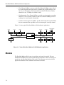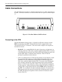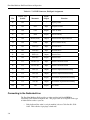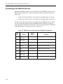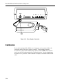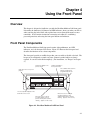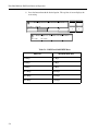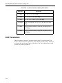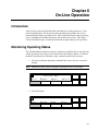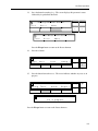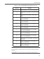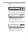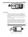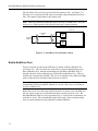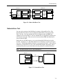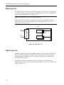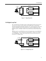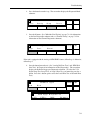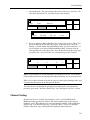
1
Excalibur Multirate DAP Installation and Operation 15D09B-1/D Milgo Solutions, Inc. 1619 N. Harrison Parkway P.O. Box 407044 Fort Lauderdale, FL 33340-7044 Internet: http://www.milgo.com 6/95 Warranty The period of warranty for the Excalibur Multirate DAP starts on the date of sale to the original end user and extends one year. Refer to Milgo Solutions, Inc. Limited Warranty for details. Milgo Solutions requires a Return Material Authorization (RMA) prior to the return of any equipment under the provisions of the warranty. Please contact your authorized reseller or the nearest Milgo support center for details. Fourth Edition, June, 1995 Excalibur and CMS are trademarks of Milgo Solutions, Inc. All other logos and product names are trademarks or registered trademarks of their respective companies. ©1999 Milgo Solutions, Inc. All rights reserved. No part of this work covered by the copyright hereon may be reproduced or copied in any form or by any means — graphic, electronic, or mechanical, including photocopying, recording, taping, or information and retrieval systems — without written permission of the publisher. Any software furnished under a license may be used or copied only in accordance with the terms of such license. Milgo Solutions, Inc. reserves the right to modify or revise all or part of this document without notice and shall not be responsible for any loss, cost, or damage, including consequential damage, caused by reliance on these materials. Printed in U.S.A. ii Milgo Solutions Customer Information Contacts CORPORATE HEADQUARTERS Milgo Solutions, Inc. 1619 North Harrison Parkway Sunrise, Florida 33323-2802, U.S.A. Tel: (954)-846-1601/(800)-333-4143 Fax: (954)-846-3935 Internet: http://www.milgo.com Call Milgo's Corporate Headquarters if you need the following information: Press 1 2 3 4 5 6 7 8 For: Billing or invoice information Orders, product delivery or availability, and repairs Sales Field service Training Employee benefits and information Corporate quality Mailing or street addresses For technical support, please contact your supplier/distributor with details of the issue. MILGO SERVICE CONTRACT CUSTOMERS: For customers with Milgo Service Contracts or service requirements, contact the following offices: AMERICAS U.S. and U.S. Multinational Milgo Solutions, Inc. 1619 North Harrison Parkway Sunrise, Florida 33323-2802 Tel: (954)-846-4569/(800)-366-0126 Fax: (954)-846-1137 EUROPE/MIDDLE EAST/AFRICA Milgo Solutions, Ltd Landata House, Station Road Hook, Hampshire, RG279JF, England Tel: +44 (0) 1256 763911 Fax: +44 (0) 1256 764717 Milgo Solutions SA Parc du Colombier 18 Rue Jules Saulnier 93206 Saint-Denis Cedex, France Tel: +331 (0) 49 33 5800 Fax: +331 (0) 49 33 5851 Milgo Solutions BV Poortweg 14 2612 PA Delft The Netherlands Tel: +31 15 269 82 82 Fax: +31 15 262 18 08 ASIA/PACIFIC Contact your Milgo affiliate support center. (See next page for addresses and phone/fax numbers.) MILGO AFFILIATE SUPPORT CENTERS: AMERICAS Region Milgo Solutions, Inc. 1619 North Harrison Parkway Sunrise, Florida 33323-2802, U.S.A. Tel: (954)-846-6116/(888)-722-2548 Fax: (954)-846-3692 email: [email protected] EUROPE/MIDDLE EAST/AFRICA Region Milgo Solutions, Ltd. Landata House, Station Road Hook, Hampshire, RG279JF, England Tel: +44 (0) 1256 761240 Fax: +44 (0) 1256 382112 email: [email protected] Internet: www.milgo.com/emea Bulletin Board Service: +44 1256 766608 (PSTN) +44 1256 744832/3/4 (ISDN) iii MILGO AFFILIATE SUPPORT CENTERS: ASIA/PACIFIC Region Milgo Solutions (Hong Kong), Ltd. Sun House 6th Floor 181 Des Voeux Road, Central Hong Kong Tel: 852-2815-1886 Fax: 852-2815-2895 Milgo Solutions (Hong Kong) supports: • China (southern provinces) • Japan • Korea • Hong Kong • Macau • Taiwan Milgo Solutions (Singapore) Pte Ltd. 26 Ayer Rajah Crescent, #04-06 Ayer Rajah Industrial Estate Singapore 139944 Tel: +65 779 2200 Fax: +65 778 5400 Milgo Solutions (Singapore) supports: • Brunei • Indonesia • Malaysia • Philippines • Singapore • Thailand • Australia • New Zealand • Rest of Indochina Cambodia Laos Myanmar Vietnam Milgo Solutions (Beijing), Inc. Room 20659 Beijing Friendship Hotel Beiing 100873 Tel: 86-10-6849-8731 Fax: 86-10-6849-8732 Milgo Solutions (Beijing) supports: • China (northern provinces) iv About This Manual Manual Description This Excalibur Multirate DAP (Digital Access Product) Installation and Operation manual provides the information you need to properly install, operate, and troubleshoot this DAP. It has been written with the assumption that you are familiar with basic data communications principles and terminology. The manual is composed of the following chapters: • Chapter 1, "Introduction" contains an overview of the DAP's capabilities and descriptions of all standard features and options. • Chapter 2, "Operating Modes" provides information about each operating mode and how it functions. It includes a detailed description of secondary channel operation, Analog, Switched 56, and ISDN integral dial backup operation, and asynchronous/synchronous conversion. • Chapter 3, "Installing the DAP" shows you how to place the unit, make the necessary cable connections, set the jumpers, and provide AC power. • Chapter 4, "Using the Front Panel" describes how to use the front panel buttons and LCD screen to move through the menus and enter commands. It also explains how to establish password protection and how to control remotely located DAPs from the local front panel. • Chapter 5, "Defining Operating Parameters" explains how to configure the DAP so that it will perform properly in your particular network environment. This chapter includes descriptions of each operating parameter and recommended setttings for typical applications. • Chapter 6, "On-Line Operation" describes the procedures you can perform while the DAP is transmitting and receiving data. These procedures include monitoring current operating status, establishing dial backup connections, and sending call messages. • Chapter 7, "Troubleshooting" explains how to use the DAP's built-in diagnostic tests to isolate the source of malfunctions in your network. • Appendix A, "Technical Specifications" • Appendix B, "ISDN Service Ordering Checklist" • Appendix C, “Quick Reference Menu Flowchart v About This Manual Terminology and Conventions The following typographical conventions are used in this manual: • References to labeled parts of a device, such as buttons and connectors, are shown in boldface. For example: The DL connector is located on the DAP’s rear panel. • References to text that appears on the control panel LCD screen are shown in this font. For example: Press the button beneath Serve to enter the Service menu. • In the front panel illustrations that accompany step-by-step instructions, the gray shading indicates which button to press. For example: 1. Press the button beneath Serve. T vi Excalibur DAP Local R em ot Addrs Serve > 1 2 3 4 E scape Top < > Table of Contents Chapter 1 - Introduction Introducing the Excalibur Multirate DAP ........................................................................................................ 1-1 Operating Modes .............................................................................................................................................. 1-1 Models.............................................................................................................................................................. 1-2 Standalone Model ...................................................................................................................................... 1-4 Central Site Model..................................................................................................................................... 1-5 Standard Features ............................................................................................................................................. 1-6 Menu-Driven Front Panel Display............................................................................................................. 1-6 Remote Control Panel................................................................................................................................ 1-6 Password Protection................................................................................................................................... 1-7 RTS-DCD Simulation................................................................................................................................ 1-7 Extended Range Operation ........................................................................................................................ 1-7 Rate Adaption ............................................................................................................................................ 1-7 Built-In Diagnostic Tests ........................................................................................................................... 1-7 Alarm Reporting ........................................................................................................................................ 1-8 Line Parameter Monitoring........................................................................................................................ 1-8 Call Messages ............................................................................................................................................ 1-8 Asynchronous/Synchronous Conversion................................................................................................... 1-9 CMS DSU Compatibility........................................................................................................................... 1-9 Multiport Frame Compatibility.................................................................................................................. 1-9 CMS Compatibility.................................................................................................................................... 1-9 Backward Compatibility.......................................................................................................................... 1-10 Options ........................................................................................................................................................... 1-11 Dual Interface .......................................................................................................................................... 1-11 Integral Dial Backup................................................................................................................................ 1-11 Model for EDRS............................................................................................................................................. 1-13 Chapter 2 - Operating Modes Overview .......................................................................................................................................................... 2-1 Interruptive Secondary Channel (Basic DDS) ................................................................................................. 2-1 Primary Channel Interface ......................................................................................................................... 2-2 Network Management Controller .............................................................................................................. 2-2 Main Channel Interruption ........................................................................................................................ 2-3 Non-Interruptive Secondary Channel (DDS-SC)............................................................................................. 2-3 Non-Interruptive Secondary Channel (Basic DDS and Clear Channel 64 Kbps) ............................................ 2-4 Clear Channel 64 Kbps .................................................................................................................................... 2-5 Customer Owned Copper Wire (LDM)............................................................................................................ 2-5 Clear Secondary Channel ................................................................................................................................. 2-5 Antistreaming................................................................................................................................................... 2-6 Analog Integral Dial Operation........................................................................................................................ 2-6 Front Panel Status Information .................................................................................................................. 2-8 Call Establishment ..................................................................................................................................... 2-8 vii Table of Contents Call Answering.......................................................................................................................................... 2-8 Call Disconnection .................................................................................................................................... 2-9 Switched 56 Integral Dial Operation ............................................................................................................... 2-9 Front Panel Status Information ............................................................................................................... 2-10 Call Establishment................................................................................................................................... 2-11 Call Answering........................................................................................................................................ 2-11 Call Disconnection .................................................................................................................................. 2-11 ISDN Integral Dial Operation........................................................................................................................ 2-12 Call Initiation .......................................................................................................................................... 2-12 Front Panel Status Information ............................................................................................................... 2-13 Call Establishment................................................................................................................................... 2-13 Call Answering........................................................................................................................................ 2-13 Call Disconnection .................................................................................................................................. 2-14 Asynchronous/ Synchronous Conversion ...................................................................................................... 2-14 Chapter 3 - Installing the DAP Overview.......................................................................................................................................................... 3-1 Unit Placement................................................................................................................................................. 3-1 Cable Connections ........................................................................................................................................... 3-2 Connecting to the DTE.............................................................................................................................. 3-2 Connecting to the Dedicated Line ............................................................................................................. 3-6 Connecting to the Analog Dial-Up Line ................................................................................................... 3-8 Connecting to the ISDN Dial-UP Line.................................................................................................... 3-10 Connecting to the Switched 56 Dial-Up Line ......................................................................................... 3-11 Connecting to the CMS Network Management System ......................................................................... 3-12 Connecting to the Clear Secondary Channel........................................................................................... 3-13 Connecting to an External Alarm............................................................................................................ 3-14 DMM Connector ..................................................................................................................................... 3-15 Setting the Jumpers........................................................................................................................................ 3-16 Setting the Pin Assignment Switches ............................................................................................................ 3-19 Aggregate Transition Board Headers ............................................................................................................ 3-22 Digital Bridge Board...................................................................................................................................... 3-22 Switch and Header Settings..................................................................................................................... 3-22 Connectors............................................................................................................................................... 3-24 User Indicator.......................................................................................................................................... 3-25 AC Power Connection ................................................................................................................................... 3-25 Calibration ..................................................................................................................................................... 3-26 Chapter 4 - Using the Front Panel Overview.......................................................................................................................................................... 4-1 Front Panel Components.................................................................................................................................. 4-1 What You Will See First.................................................................................................................................. 4-2 Moving Through the Menus ............................................................................................................................ 4-2 Status Display .................................................................................................................................................. 4-4 Entering Unit Addresses .................................................................................................................................. 4-5 Assigning NCP Channel .................................................................................................................................. 4-7 viii Table of Contents Establishing Password Protection .................................................................................................................... 4-8 Entering the Password ............................................................................................................................... 4-8 Changing the Password.............................................................................................................................. 4-9 Locking Front Panel Functions................................................................................................................ 4-10 Unlocking Front Panel Functions ............................................................................................................ 4-11 Establishing a Security Code ................................................................................................................... 4-11 Front Panel Test ............................................................................................................................................. 4-13 Auto-Learn Network ...................................................................................................................................... 4-14 Event Displays ............................................................................................................................................... 4-15 Chapter 5 - Defining Operating Parameters Overview .......................................................................................................................................................... 5-1 Entering the Service Menu............................................................................................................................... 5-1 Entering the Configuration Menu .................................................................................................................... 5-5 Defining Individual Parameters ....................................................................................................................... 5-7 DAP Parameters ............................................................................................................................................... 5-8 Location ................................................................................................................................................... 5-11 Network ................................................................................................................................................... 5-11 RTS .......................................................................................................................................................... 5-11 DCD......................................................................................................................................................... 5-11 Transmit Clock ........................................................................................................................................ 5-12 Port Receive Clock .................................................................................................................................. 5-12 CTS Delay ............................................................................................................................................... 5-13 Squelch Primary Transmitter ................................................................................................................... 5-13 DSR Off ................................................................................................................................................... 5-13 DSR On.................................................................................................................................................... 5-13 EIA Pin 21 ............................................................................................................................................... 5-14 Beeper ...................................................................................................................................................... 5-14 EIA Pin 18 ............................................................................................................................................... 5-14 Remote Digital Loop ............................................................................................................................... 5-14 DTR Control ............................................................................................................................................ 5-15 CTS Control............................................................................................................................................. 5-15 RTS Simulation ....................................................................................................................................... 5-15 DCD Simulation ...................................................................................................................................... 5-15 Protocol.................................................................................................................................................... 5-18 Interface ................................................................................................................................................... 5-18 Range ....................................................................................................................................................... 5-19 Latching Loopback .................................................................................................................................. 5-19 Transmit Calibrate ................................................................................................................................... 5-19 Pattern...................................................................................................................................................... 5-19 Secondary Channel .................................................................................................................................. 5-19 Network Delay......................................................................................................................................... 5-20 Automatic Poll ......................................................................................................................................... 5-21 Modify Drop Table .................................................................................................................................. 5-22 One's Density........................................................................................................................................... 5-22 Channel Parameters........................................................................................................................................ 5-22 Selecting the DTE Data Rate................................................................................................................... 5-22 Channel Assignment ................................................................................................................................ 5-26 ix Table of Contents Naming Channels .................................................................................................................................... 5-27 Port Rate Configuration ................................................................................................................................. 5-30 RCP Parameters ............................................................................................................................................. 5-32 Controller ................................................................................................................................................ 5-34 RTS Mode ............................................................................................................................................... 5-34 DCD Mode .............................................................................................................................................. 5-34 Secondary Channel Format ..................................................................................................................... 5-34 Local Diagnostics.................................................................................................................................... 5-35 Remote Diagnostics................................................................................................................................. 5-35 Alarm Detection ...................................................................................................................................... 5-35 Local Alarm Display ............................................................................................................................... 5-36 Analog Regeneration............................................................................................................................... 5-36 Digital Regeneration ............................................................................................................................... 5-36 Diagnostic Compatibility ........................................................................................................................ 5-36 Route Secondary Channel ....................................................................................................................... 5-36 Analog Dial Parameters ................................................................................................................................. 5-38 Dial Mode................................................................................................................................................ 5-39 Speed ....................................................................................................................................................... 5-40 Transmit Clock........................................................................................................................................ 5-40 Dialer....................................................................................................................................................... 5-40 Wait to Dial ............................................................................................................................................. 5-41 Call Progress ........................................................................................................................................... 5-41 Automatic Dial ........................................................................................................................................ 5-41 Automatic Dial Timer ............................................................................................................................. 5-41 Switch to Dial.......................................................................................................................................... 5-42 Automatic Disconnect ............................................................................................................................. 5-42 Retry Attempts ........................................................................................................................................ 5-42 Dedicated Line Test ................................................................................................................................ 5-42 Line Test Interval .................................................................................................................................... 5-42 DCD Threshold ....................................................................................................................................... 5-43 Answer .................................................................................................................................................... 5-43 Answerback............................................................................................................................................. 5-44 Transmit Equalizer .................................................................................................................................. 5-44 Program Resistor ..................................................................................................................................... 5-44 Port RTS-DCD Simulation...................................................................................................................... 5-44 Switched 56 Dial Parameters......................................................................................................................... 5-44 Call Progress ........................................................................................................................................... 5-46 Automatic Dial ........................................................................................................................................ 5-46 Automatic Dial Timer ............................................................................................................................. 5-46 Switch to Dial.......................................................................................................................................... 5-46 Automatic Disconnect ............................................................................................................................. 5-47 Retry Attempts ........................................................................................................................................ 5-47 Dedicated Line Test ................................................................................................................................ 5-47 Line Test Interval .................................................................................................................................... 5-48 Answer .................................................................................................................................................... 5-48 Port RTS-DCD Simulation...................................................................................................................... 5-49 Ring Detect.............................................................................................................................................. 5-49 ISDN Dial Parameters ................................................................................................................................... 5-50 Switch Type ............................................................................................................................................ 5-51 x Table of Contents Dial Mode ................................................................................................................................................ 5-51 Transmit Clock ........................................................................................................................................ 5-51 Call Progress............................................................................................................................................ 5-51 Automatic Dial......................................................................................................................................... 5-52 Automatic Dial Timer.............................................................................................................................. 5-52 Switch to Dial .......................................................................................................................................... 5-52 Automatic Disconnect ............................................................................................................................. 5-52 Retry Attempts......................................................................................................................................... 5-53 Dedicated Line Test ................................................................................................................................. 5-53 Line Test Interval..................................................................................................................................... 5-53 Answer..................................................................................................................................................... 5-53 Port RTS-DCD Simulation ...................................................................................................................... 5-54 Parameter Thresholds..................................................................................................................................... 5-54 User LED ....................................................................................................................................................... 5-56 Turning off the User LED........................................................................................................................ 5-57 Alias Parameter .............................................................................................................................................. 5-57 System Submenu ............................................................................................................................................ 5-59 Chapter 6 - On-Line Operation Introduction ...................................................................................................................................................... 6-1 Monitoring Operating Status............................................................................................................................ 6-1 Line Quality Statistics .................................................................................................................................... 6-11 Alarms ............................................................................................................................................................ 6-19 ISDN Dial Backup Alarms ...................................................................................................................... 6-22 Viewing Stored Alarms ........................................................................................................................... 6-23 Dial Backup Procedures ................................................................................................................................. 6-25 Entering Telephone Numbers .................................................................................................................. 6-26 Entering Service Profile Identification Number ...................................................................................... 6-30 Originating Dial Backup Calls................................................................................................................. 6-31 Disconnecting Dial Backup Calls ............................................................................................................ 6-31 Analog Dial Line Tests .................................................................................................................................. 6-32 Switched 56 Dial Line Tests .......................................................................................................................... 6-36 ISDN Dial Line Tests..................................................................................................................................... 6-37 Activating the Tests ................................................................................................................................. 6-38 Activating Timed Tests............................................................................................................................ 6-39 Activating Loop Tests.............................................................................................................................. 6-40 Sending Call Messages................................................................................................................................... 6-41 Chapter 7 - Troubleshooting Overview .......................................................................................................................................................... 7-1 Initial Checks ................................................................................................................................................... 7-1 Fault Isolation Strategy .................................................................................................................................... 7-1 Self-Error Test ........................................................................................................................................... 7-2 Local-Error Test......................................................................................................................................... 7-3 End-to-End Error Test ............................................................................................................................... 7-4 Network-Error Test.................................................................................................................................... 7-5 xi Table of Contents DDS Loop Test ......................................................................................................................................... 7-6 Digital Loop Test ...................................................................................................................................... 7-6 V.54 Digital Loop Test.............................................................................................................................. 7-7 Loop 2 and Loop 2 Error Tests ................................................................................................................. 7-8 Service Loops .................................................................................................................................................. 7-9 CSU Loopback Test .................................................................................................................................. 7-9 Non-Latching Loopback Test.................................................................................................................... 7-9 Latching Loopback Test.......................................................................................................................... 7-10 Activating the Tests ....................................................................................................................................... 7-10 Activating Timed Tests ........................................................................................................................... 7-12 Activating Loop Tests ............................................................................................................................. 7-13 Individual Port Testing............................................................................................................................ 7-14 Channel Testing....................................................................................................................................... 7-15 RTN Function ................................................................................................................................................ 7-16 Isolating Network Problems .......................................................................................................................... 7-17 Appendix A - Technical Specifications Appendix B - ISDN Service Ordering Checklist Appendix C - Quick Reference Flowchart Appendix D - Regulatory Information xii Table of Contents Figures 1-1 1-2 1-3 1-4 3-1 3-2 3-3 3-4 3-5 3-6 3-7 3-8 3-9 3-10 3-11 4-1 4-2 4-3 4-4 5-1 7-1 7-2 7-3 7-4 7-5 7-6 7-7 7-8 7-9 7-10 7-11 7-12 Typical Excalibur Multirate DAP Multimode Applications ............................................................... 1-2 Excalibur Card Carrier ........................................................................................................................ 1-5 Typical Menu Display......................................................................................................................... 1-6 Dial Backup Connection ................................................................................................................... 1-12 Excalibur Multirate DAP Rear Panel .................................................................................................. 3-2 RS-232 DTE Connection .................................................................................................................... 3-3 V.35 DTE Connection......................................................................................................................... 3-3 Dedicated Line Connection................................................................................................................. 3-7 Analog or ISDN Dial Line Cable Connections ................................................................................... 3-9 Switched 56 Dial Line Cable Connections ....................................................................................... 3-11 Removing Top Cover ........................................................................................................................ 3-16 Jumper Locations .............................................................................................................................. 3-17 DBB Switchbank and Header Locations........................................................................................... 3-23 DBB Connectors ............................................................................................................................... 3-24 Power Supply Connection................................................................................................................. 3-26 Excalibur Multirate DAP Front Panel ................................................................................................. 4-1 Top Level Menu.................................................................................................................................. 4-2 Status Display...................................................................................................................................... 4-4 Event Displays .................................................................................................................................. 4-16 Secondary Channel Data Routed to Dial-Up Line ............................................................................ 5-37 Self-Error Test..................................................................................................................................... 7-3 Local-Error Test (Interface Circuitry)................................................................................................. 7-3 Local-Error Test (Customer's Lines)................................................................................................... 7-4 End-to-End Error Test......................................................................................................................... 7-5 Network-Error Test ............................................................................................................................. 7-5 DDS Loop Test ................................................................................................................................... 7-6 Digital Loop Test ................................................................................................................................ 7-7 V.54 Digital Loop Test ....................................................................................................................... 7-7 Loop 2 Test ........................................................................................................................................ 7-8 Loop 2 Error Test ................................................................................................................................ 7-8 CSU Loopback Test ............................................................................................................................ 7-9 Non-Latching and Latching Loopback Tests .................................................................................... 7-10 Tables 1-1 2-1 2-2 3-1 3-2 3-3 3-4 3-5 3-6 3-7 3-8 Excalibur Multirate DAP Part Numbers ............................................................................................. 1-3 DDSNI and C64NI DTE Rates ........................................................................................................... 2-4 Clear Secondary Channel Rates .......................................................................................................... 2-6 RS-232 DTE Connector, Pin/Signal Assignments .............................................................................. 3-4 V.35 DTE Connector, Pin/Signal Assignments .................................................................................. 3-6 Dedicated Line Connector, Pin/Signal Assignments .......................................................................... 3-8 Analog Dial Line Cable Connector, Pin/Signal Assignments............................................................. 3-9 ISDN Dial Line Cable Connector, Pin/Signal Assignments ............................................................. 3-10 Switched 56 Dial Line Cable Connector, Pin/Signal Assignments................................................... 3-12 Network Management System Connector, Pin/Signal Assignments ................................................ 3-13 Clear Secondary Channel (NMI) Connector, Pin/Signal Assignments............................................. 3-14 xiii Table of Contents 3-9 3-10 3-11 3-12 5-1 5-2 5-3 5-4 5-5 5-6 5-7 5-8 5-9 5-10 5-11 5-12 5-13 5-14 5-15 5-16 6-1 6-2 7-1 xiv External Alarm Connector, Pin/Signal Assignments........................................................................ 3-15 Jumper Settings................................................................................................................................. 3-18 Switchbank and Switch Settings....................................................................................................... 3-20 Switch Settings, Older Standalone and Central Site DAPs .............................................................. 3-21 DDSNI and C64NI DTE Rates........................................................................................................... 5-4 DAP Parameters.................................................................................................................................. 5-9 RTS-CTS Delay Related to V.13 RTS-DCD Simulation ................................................................. 5-17 Worst Case RTS-CTS Delay Related to Out of Band RTS-DCD Simulation................................. 5-18 Clear Secondary Channel Rates........................................................................................................ 5-20 Remote Unit Response Time ............................................................................................................ 5-21 Synchronous Rate Adaption ............................................................................................................. 5-30 Asynchronous Rate Adaption ........................................................................................................... 5-31 Synchronous Rate Adaption (Older DAPs) ...................................................................................... 5-31 Asynchronous Rate Adaption (Older DAPs).................................................................................... 5-32 RCP Parameters ................................................................................................................................ 5-33 Secondary Channel Format............................................................................................................... 5-35 Analog Dial Parameters .................................................................................................................... 5-38 Switched 56 Dial Parameters............................................................................................................ 5-45 ISDN Dial Parameters ...................................................................................................................... 5-50 Parameter Thresholds ....................................................................................................................... 5-54 Receive Level Insertion Loss Ranges................................................................................................. 6-3 Analog and ISDN IDBU Telephone Number Characters................................................................. 6-29 LQS Troubleshooting Reference Chart ............................................................................................ 7-17 Important Safety Instructions 1. Never install telephone wiring during a lightning storm. 2. Never install telephone jacks in wet locations unless the jack is specifically designed for wet locations. 3. Never touch uninsulated telephone wires or terminals unless the telephone line has been disconnected at the network interface. 4. Use caution when installing or modifying telephone lines. 5. Avoid using a telephone (other than a cordless type) during an electrical storm. There may be a remote risk of electrical shock from lightning. 6. Do not use the telephone to report a gas leak in the vicinity of the leak. Caution: To ensure compliance with government regulations, do not install or operate this product until you have read the information contained in Appendix D. xv Test scape Top User 1 2 3 4 xcalib ur DA P Excalibur Multirate DAP Chapter 1 Introduction Introducing the Excalibur Multirate DAP The Excalibur Multirate DAP (Digital Access Product) provides a versatile interface between your data terminal equipment (DTE) and all the digital data services. Efficient and economical performance is provided in both point-to-point and multipoint network configurations. The DAP operates at digital line speeds of 2.4, 4.8, 9.6, 19.2, 56, and 64 Kbps. DAP control is quick and easy with the Excalibur Multirate DAP's menu-driven front panel display. Clear English prompts displayed on a 48-character LCD screen guide you through each operating procedure. To enter a command, simply press the button beneath the desired menu option. With the Excalibur Multirate DAP, you can control any remote Excalibur DAP in the network from the local DAP's front panel. By entering the remote unit's address into the local DAP, you can perform operating procedures as if you were at that site. This feature eliminates the need to have trained operators at remote sites. For even more comprehensive network control, the Excalibur Multirate DAP can operate with one of Milgo's Communications Management Series (CMS) network management systems. A CMS system provides sophisticated data base management, performance analysis, fault isolation, and network restoral capabilities. Operating Modes There are six operating modes for the Excalibur Multirate DAP: • Interruptive Secondary Channel (Basic DDS®) - provides an interruptive secondary channel for diagnostic testing. Data transfer between the DTE and the Digital Data Service (DDS) network is interrupted when the secondary channel is in use. • Non-Interruptive Secondary Channel (DDS-SC) - provides an out-of-band secondary channel supplied by the DDS-SC service which can be used as a noninterruptive secondary channel or as a clear secondary channel for user applications. The DDS network allows additional bandwidth for the secondary channel and does not interrupt primary channel data. • Non-Interruptive Secondary Channel (Basic DDS) - provides a non-interruptive secondary channel or a clear secondary channel over basic DDS lines in exchange for a small amount of bandwidth. 1-1 Excalibur Multirate DAP Installation and Operation • Clear Channel 64 Kbps - operates on the Clear Channel 64 Kbps service offered by Accunet Spectrum of Digital Services (ASDS®) and provides 64 Kbps to use for data. An interruptive secondary channel is provided. When the secondary channel is in use, 57.6 Kbps is available for data. • Non-Interruptive Clear Channel 64 Kbps - provides a non-interruptive secondary channel or a clear secondary channel over the Clear Channel 64 Kbps service in exchange for a small amount of bandwidth. • Customer owned copper wire (LDM) - provides short-haul point-to-point limited distance communications capabilities and a non-interruptive secondary channel. Figure 1-1 shows typical Excalibur Multirate DAP multimode applications. 56 Kbps EXCALIBUR MR DAP 56 Kbps EXCALIBUR MR DAP 56 Kbps EXCALIBUR MR DAP EXCALIBUR C.S. DAPS 19.2 Kbps 19.2 Kbps EXCALIBUR MR DAP EXCALIBUR MR DAP PORT SHARING 19.2 Kbps EXCALIBUR MP DAP 56 Kbps DDS DDS-SC MULTIDROP 56 Kbps DDS CIRCUIT LDM CIRCUIT 2.4 TO 64 Kbps EXCALIBUR MR DAP EXCALIBUR MR DAP 9.6 Kbps EXCALIBUR MR DAP 9.6 Kbps EXCALIBUR MP DAP 9.6 Kbps Figure 1-1. Typical Excalibur Multirate DAP Multimode Applications Models The Excalibur Multirate DAP comes in standalone and central site models. The part number/serial number label is located on the bottom of the DAP. Table 1-1 lists the part number for each Excalibur Multirate DAP model. The following sections describe the physical characteristics of the standalone and central site models. 1-2 Introduction Table 1-1. Excalibur Multirate DAP Part Numbers Part Number Description 15-09B112001xx RS-232-E DAP, Standalone, Aggregate Card Part No. 15P09AA-6 15-05B213000xx RS-232-E DAP, Central Site (CS-1), Aggregate Card Part No. 15P0501D-3 15-05B313000xx RS-232-E DAP, Central Site (CS-2), Aggregate Card Part No. 15P0501D-3 15-09B512001xx RS-232-E/CCITT V.35 DAP, Standalone, Aggregate Card Part No. 15P09AA-6 15-05B613000xx CCITT V.35 DAP, Central Site (CS-1), Aggregate Card Part No. 15P0501D-3 15-05B713000xx CCITT V.35 DAP, Central Site (CS-2), Aggregate Card Part No. 15P0501D-3 15-09B112A01xx RS-232-E with Analog IDBU2 DAP, Standalone, Aggregate Card Part No. 15P09AA-6 15-05B213A00xx RS-232-E with Analog IDBU2 DAP, Central Site (CS-1), Aggregate Card Part No. 15P0501D-3 15-05B313A00xx RS-232-E with Analog IDBU2 DAP, Central Site (CS-2), Aggregate Card Part No. 15P0501D-3 15-09B512A01xx RS-232-E/CCITT V.35 with Analog IDBU2 DAP, Standalone, Aggregate Card Part No. 15P09AA-6 15-05B613A00xx CCITT V.35 with Analog IDBU2 DAP, Central Site (CS-1), Aggregate Card Part No. 15P0501D-3 15-05B713A00xx CCITT V.35 with Analog IDBU2 DAP, Central Site (CS-2), Aggregate Card Part No. 15P0501D-3 15-09B112B01xx RS-232-E with Switched 56 IDBU DAP, Standalone, Aggregate Card Part No. 15P09AA-6 15-05B213B00xx RS-232-E with Switched 56 IDBU DAP, Central Site (CS-1), Aggregate Card Part No. 15P0501D-3 15-05B313B00xx RS-232-E with Switched 56 IDBU DAP, Central Site (CS-2), Aggregate Card Part No. 15P0501D-3 15-09B512B01xx RS-232-E/CCITT V.35 with Switched 56 IDBU DAP, Standalone, Aggregate Card Part No. 15P09AA-6 1-3 Excalibur Multirate DAP Installation and Operation Table 1-1. Excalibur Multirate DAP Part Numbers (Continued) Part Number Description 15-05B613B00xx CCITT V.35 with Switched 56 IDBU DAP, Central Site (CS-1), Aggregate Card Part No. 15P0501D-3 15-05B713B00xx CCITT V.35 with Switched 56 IDBU DAP, Central Site (CS-2), Aggregate Card Part No. 15P0501D-3 15-09B112C01xx RS-232-E with ISDN U IDBU DAP, Standalone, Aggregate Card Part No. 15P09AA-6 15-05B213C00xx RS-232-E with ISDN U IDBU DAP, Central Site (CS-1), Aggregate Card Part No. 15P0501D-3 15-05B313C00xx RS-232-E with ISDN U IDBU DAP, Central Site (CS-2), Aggregate Card Part No. 15P0501D-3 15-09B512C01xx RS-232-E/CCITT V.35 with ISDN U IDBU DAP, Standalone, Aggregate Card Part No. 15P09AA-6 15-05B613C00xx CCITT V.35 with ISDN U IDBU DAP, Central Site (CS-1), Aggregate Card Part No. 15P0501D-3 15-05B713C00xx CCITT V.35 with ISDN U IDBU DAP, Central Site (CS-2), Aggregate Card Part No. 15P0501D-3 15-05B313600xx RS-232-E EDRS DAD, Central Site (CS-2), Aggregate Card Part No. 15P0501D-3 15-05B713600xx CCITT V.35 EDRS DAD, Central Site (CS-2), Aggregate Card Part No. 15P0501D-3 * xx denotes the software revision level. Standalone Model The standalone Excalibur Multirate DAP is housed in a 3"x8"x12" (7.6 cm x 20.3 cm x 30.5 cm) plastic housing. The housing consists of a top and bottom half, fastened together with two screws. The front and rear panels slide vertically into the bottom half of the housing and are held in place by the top half. The DAP can be placed on any flat surface or it can be mounted in a standard 19-inch wide rack (using an optional kit). The DAP's front panel contains an LCD information screen, two LED indicators, and eight pushbuttons. The rear panel contains the interface connectors used to attach to the DTE, telephone lines, and other network components. The unit is powered by an external power supply operating at 92 to 127 VAC. 1-4 Introduction Central Site Model The central site Excalibur Multirate DAP consists of a printed circuit (p.c.) card and a transition board (vertical rear panel) that are designed to be housed in the high-density Excalibur Card Carrier (Figure 1-2). Each card carrier can house up to 16 p.c. cards. Six card carriers, holding up to 96 single port Excalibur Multirate central site DAPs, can be installed in a single 6-foot rack. The card carrier contains a Master Control Panel that can control any of the 96 DAPs in the rack. For more information on the Excalibur Card Carrier, refer to that product's instruction manual. Note: The Aggregate card requires a single slot if the DAP has no IDBU or if it is equipped with Switched 56 or ISDN IDBU. If the DAP is equipped with Analog IDBU, the Aggregate card requires two card slots since the front portion of the card slot immediately to the left of this card as viewed from the front of the card carrier must be vacant. POE POE Excalibur SE ES Figure 1-2. Excalibur Card Carrier 1-5 Excalibur Multirate DAP Installation and Operation Standard Features The Excalibur Multirate DAP comes with a full complement of standard features, as described in the following sections. Menu-Driven Front Panel Display The Excalibur Multirate DAP has a menu-driven front panel display that makes monitoring, configuring, and testing the DAP quick and easy. The two-line LCD screen guides you through the various operating procedures by displaying menu prompts on the top line and selectable options on the bottom line. To select an option, simply press the button beneath it. Figure 1-3 shows a typical menu display in which you are prompted to select the DTE data rate. The LCD screen is backlit for ease of viewing. If two minutes elapse without a front panel button being pressed, the screen dims to reduce power consumption. Data Rate = 56000 56000 19200 9600 Escape Top 4800 > 1 Figure 1-3. Typical Menu Display Remote Control Panel The Remote Control Panel (RCP) feature allows you to control remotely located Excalibur DAPs from the front panel of the local DAP. The RCP feature may be activated by both central and remote DAPs. The only exception is when operating in Interruptive Secondary Channel (Basic DDS) mode in a multipoint configuration, the RCP function can only be started from the central unit. By entering the remote unit's address into the local DAP's front panel, you can perform any operating procedure as if you were at that site, with the following exceptions: 1-6 • The T7 address cannot be changed. • The Digital Data Service mode and line speed cannot be changed. • The End-to-End Error, V.54 Loop 2 and L2 Error, and the Local-Error and Network-Error tests should not be performed. Introduction Password Protection The Excalibur Multirate DAP provides a password protection feature to prevent users from accessing certain front panel functions. This feature enables you to lock out any or all of the following functions to users who do not enter the proper password: configuration (including secondary channel configuration), remote unit control, dial backup operation, diagnostic testing, the Digital Data Service mode, and the T7 address. The password can be any three-character alphanumeric code. RTS-DCD Simulation Two user-selectable methods of RTS-DCD simulation are provided as a means of transmitting control signaling information: • V.13 - is only supported on synchronous ports. • Out of Band - can be enabled on synchronous and asynchronous ports. This method does not add bits to the user data stream and allows the use of RTS-DCD Simulation with equipment that is sensitive to in-band signaling. Extended Range Operation The DAP receiver accommodates a nominal loop loss of 0 to -34 dB which complies with the requirements of AT&T Publication 62310. The extended range feature automatically allows operation on loops that have an attenuation rate of -40 dB for line rates lower than 56 Kbps, and -45 dB for line rates of 56 and 72 Kbps. The performance in this range is dependent on the telephone company equipment. Rate Adaption Rate adaption allows the DTE interface to operate at a lower data rate than the DDS line rate. This feature is available when the DAP is operating with the non-interruptive secondary channel technology on Basic DDS service or Clear Channel 64 Kbps service. Built-In Diagnostic Tests The Excalibur Multirate DAP contains an extensive array of diagnostic tests that help you quickly isolate the source of network malfunctions. From the local site, you can initiate Aggregate, Channel (available for Basic DDS with non-interruptive secondary channel mode), and port level tests on both the local and remote site DAPs. The following tests are included: • Self-Error 1-7 Excalibur Multirate DAP Installation and Operation • End-to-End Error • DDS Loop • Digital Loop, standard and V.54 • V.54 Loop 2 and L2 Error (V.54 Loop 2 not available for DDS with interruptive secondary channel mode) • Local-Error • Network-Error In addition to these operator-initiated tests, the Excalibur Multirate DAP automatically runs an internal self-test each time it is powered up. This test verifies the functionality of the DAP's internal circuitry. Any failures are immediately displayed on the front panel. Alarm Reporting To alert you to potential problems in the network, the DAP reports a wide variety of alarm conditions. You can set the DAP to sound a beeper, light a LED indicator, and/or display an alarm message when it detects an alarm condition. Alarm conditions are also reported to the CMS network management system (if the network is so equipped). The DAP stores the reported alarms in memory. Line Parameter Monitoring The Excalibur Multirate DAP continuously monitors and computes the values of a number of key DDS line parameters. Monitored parameters include line availability statistics, receive level, and signal quality. Call Messages The Excalibur Multirate DAP allows you to exchange messages with a remote DAP operator without making costly telephone calls. With this feature, you can enter up to 10 different numerical codes (0 - 9 ), each signifying a previously agreed upon message. The DAP then sends the code through the secondary channel to the remote unit. This feature is not available for DDS with interruptive secondary channel mode or Clear Channel 64 Kbps with interruptive secondary channel mode. 1-8 Introduction Asynchronous/Synchronous Conversion The Excalibur Multirate DAP can be set to operate with asynchronous or synchronous DTEs. When operating with asynchronous DTEs, the DAP converts the data into a synchronous format using the method specified in CCITT Recommendation V.14. The converter protects against data loss by compensating for small data rate differences between the DTE and the DAP. CMS DSU Compatibility The Excalibur Multirate DAP can operate with Milgo's CMS DSU products. Compatibility is provided for primary data transfers between units, T7 transfers between units, and for Loops and Self-Test. Multiport Frame Compatibility The Excalibur Multirate DAP can be connected to a multidrop network made up of Excalibur Multiport DAPs, and can interface to any one channel in the aggregate data stream. The unit can operate as a multidrop central or remote. It operates with the same DDS line rates and supports the same DTE data rates as the Excalibur Multiport DAP. This feature is available when the DAP is operating with the non-interruptive secondary channel technology on Basic DDS service. CMS Compatibility For those networks that require comprehensive management, testing, and control features, the Excalibur Multirate DAP can operate with Milgo's CMS network management systems. A CMS system provides the following capabilities: • Line Quality Statistics (LQS) - allows you to measure and graphically display the quality of a transmission line from your central site console. LQS measures the following line availability statistics: percentage of time transmit levels, receive levels, and signal quality are within predefined thresholds; percentage of time the DDS circuit is available for use; percentage of time the DAP is receiving a valid signal from the network; number of Out of Service codes, Abnormal Station codes, network framing errors, and unknown control codes received; number of multiport/multidrop resynchronizations for each drop and total number of multiport/multidrop resynchronizations; number of times the central DAP has resynchronized the entire network (global resync count); number of seconds receive line fault conditions and active network service loops occur. • Database management - provides you with a complete record of your network's structure, including all sites, components, and channels. A network map display is available as a visual aid when troubleshooting large networks. 1-9 Excalibur Multirate DAP Installation and Operation • Event files - keep a record of all significant network events (alarms, tests, etc.). • Network management reports - consolidate network status information so that you can analyze your network's overall performance. Reports can be generated on every major database item. • Network diagnostics - scan all CMS-compatible components in the network, reporting any irregular conditions. Tests can be run on any network component from the central site console. Can receive alarms from anywhere in the network. • Serial number reporting - assists in inventory and identification of network DAPs. Each DAP is assigned a serial number, which is reported to the system upon request. Backward Compatibility The Excalibur Multirate DAP is able to communicate over the main channel and dial backup lines with older Excalibur Multirate and Excalibur Multiport DAPs. For customers who have installed current software revisions only, the following conditions apply: • The following synchronous port data rates are only available for standalone units equipped with Part No. 15-09Bxx2x0xxx and central site units equipped with Part No. 15-05Bxx3x0xxx: 8.4, 10.8, 13.2, 15.6, 18, 20.4, 21.6, 22.8, 24, 25.2, 26.4, 27.6, 28.8, 30, 31.2, 32.4, 33.6, 34.8, 36, 37.2, 39.6, 40.8, 42, 43.2, 44.4, 45.6, 46.8, 48, 49.2, 50.4, and 51.6 Kbps. The 56 Kbps rate when the DAP is operating with the non-interruptive secondary channel technology on Clear Channel 64 Kbps service. • The following asynchronous port data rates are only available for standalone units equipped with Part No. 15-09Bxx2x0xxx and central site units equipped with Part No. 15-05Bxx3x0xxx: 24, 28.8, 48, and 57.6 Kbps. Standalone Excalibur Multirate DAPs (Models 15-09B) are equipped with Aggregate card Part No. 15P09AA. Older standalone DAPs (Models 15-05A and 15-05B) are equipped with a Model A (Part No. 15P0501A) or Model C (Part No. 15P0501C) Aggregate card. Central site Excalibur Multirate DAPs are equipped with a Model D Aggregate card (Part No. 15P0501D). Older central site DAPs are equipped with a Model A (Part No. 15P0501A) or Model C (Part No. 15P0501C) Aggregate card. If you install the current software revision on a unit equipped with a Model A or C Aggregate card, the following conditions apply in addition to those previously listed: 1-10 • LADC operation is provided. • The transmitter must be calibrated whenever the power supply is changed as described in Chapter 3, "Calibration." Introduction • The extended range feature can be enabled from the front panel for all DTE rates when the service is set for LADC or LDM. For all other services, it can be enabled when the DTE rate is 19.2 Kbps or greater. Extended range operation is automatic for units equipped with the Model D or 15P09AA-1 Aggregate card. Options The Excalibur Multirate DAP provides several options to meet your specific network requirements. The options are described in the following sections. Dual Interface The dual interface option provides a V.35 interface connection in addition to the standard RS-232-E connection. Simply select the V.35 option from the front panel, change a jumper setting on the printed circuit card, and connect to the V.35 adapter instead of the RS-232-E connector. Integral Dial Backup You can select from the following Integral Dial Backup (IDBU) options: • 2-wire Analog IDBU • 4-wire Switched 56 Kbps IDBU • 2-wire Integrated Services Digital Network (ISDN) IDBU An IDBU option allows you to decrease your network's down time with dial backup in the event the network or digital lines go down. (See Figure 1-4.) The dial backup telephone line connection can be established automatically, manually, or in response to CMS network management system commands. When set for automatic operation, the DAP automatically initiates dial backup calls in response to user-selectable criteria (such as loss of signal on the digital line). With manual operation, dial backup calls can be initiated by pressing the proper buttons on the DAP's front panel. In networks equipped with a CMS network management system, dial backup calls can be initiated from the CMS console. Analog IDBU can operate in either Programmable or Permissive Mode. In Programmable Mode, a limiting resistor in the telephone company's data jack programs the DAP so that the signal level received at the central office does not exceed -12 dBm. In Permissive Mode, the DAP's transmit level is fixed internally at -9 dBm. Both modes support tone and pulse dialing. 1-11 Excalibur Multirate DAP Installation and Operation CPU EXCALIBUR DAP DIGITAL LINE FAILURE EXCALIBUR DAP DTE DIAL BACKUP LINE Figure 1-4. Dial Backup Connection Switched 56 IDBU operates at 56 Kbps over MCI's Switched 56 Service, AT&T's Accunet Switched 56 Service, or Sprint's Enhanced Switched 56 Service, which does not require suppression of echo cancelers. It complies with all requirements of AT&T's Accunet Switched 56 Service, with AT&T Publications 62310 and 41458, and with Sprint's Specification TS-0046. The IDBU accommodates a nominal loop loss of 0 to -31 dB which complies with the requirements of AT&T Publication 62310. It automatically operates in extended range to accommodate loop loss from -32 to -45 dB. The performance in this range is dependent on the telephone company equipment. The ISDN IDBU operates over the ISDN Basic Rate service. This service provides two full-duplex 64-Kbps channels (B-channels) for transporting data and one full-duplex 16Kbps access channel (D-channel) for carrying control or signaling information. The ISDN IDBU operates on one 64-Kbps B-channel and the 16-Kbps D-channel. The IDBU complies with the following documents: 1-12 • All requirements of ANSI North American Standard T1.601 - 1992, "Integrated Services Digital Network (ISDN) - Basic Access Interface for Use on Metallic Loops for Application on the Network Side of the NT (Layer 1 Specification)." • All network requirements of Bellcore Special Report SR-NWT-001937, Issue 1, Feb. 1991, "National ISDN-1." • Bellcore Technical Reference TR-TSY-000793, Issue 1, Oct. 1988, "ISDN DChannel Exchange Access Signaling and Switching Requirements (Layer 2)." • Bellcore Technical Reference TR-TSY-000268, Issue 3, May 1989 and Supplement 1, June 1990, "ISDN Access Call Control Switching and Signaling Requirements (Layer 3)." • Northern Telecom Document No. NIS-S208-4, October 1988, "ISDN Basic Rate Access User Network Interface Specification." • AT&T Document 5D5-900-311, Issue 1.01, March 1989, "5ESS Switch ISDN Basic Rate Interface Specification, 5E5 Generic Program." Introduction The ISDN IDBU supports AT&T 5ESS, NTI DMS-100, and National ISDN-1 switch types. Appendix B provides a checklist to use when ordering Basic ISDN Service from your local telephone company. Model for EDRS The Excalibur Multirate DAP is also available in a model designed to operate with the Excalibur Dial Restoral System (EDRS). This model is called an Excalibur Multirate Dedicated Access Device (DAD). The EDRS provides dial backup by routing data transmission to dial backup lines whenever a dedicated digital circuit fails. The EDRS provides dial backup for Excalibur Multirate and Excalibur Multiport DADs in both point-to-point and multidrop applications. The EDRS allows concurrent dial backup of up to four dedicated circuits (point-to-point and/or multidrop) per card carrier. For example, four 3-drop multidrop circuits can be in dial backup at the same time. In a 6-card carrier system (one full rack), the EDRS allows concurrent dial backup of up to 24 circuits. 1-13 Chapter 2 Operating Modes Overview This chapter provides information about each operating mode and how it functions. It includes a detailed description of secondary channel operation, integral dial operation, and asynchronous/synchronous conversion. Interruptive Secondary Channel (Basic DDS) The Interruptive Secondary Channel (Basic DDS) operating mode provides an interruptive secondary channel. This feature allows you to perform diagnostics and Remote Control Panel (RCP) functions on a unit that does not have a dedicated secondary channel. Data transfer between the DTE and the DDS network is interrupted when the secondary channel is in use. When operating in this mode, the Excalibur Multirate DAP can operate with Milgo's CMS DSU RD and CMS 6424 products. The level of compatibility provided with the current CMS DSU 500 RD, CMS DSU 556 RD, and CMS 6424 products is as follows: • Primary data transfers between units. • T7 data transfers between units (once a remote has been selected). • Loops and Self tests. • End-to-End test is compatible with the CMS DSU 500 RD when the test pattern is 511, and is compatible with the CMS 6424. It is not compatible with the CMS DSU 556 RD. • RCP feature is not compatible. The level of compatibility provided with the current DSU 500 RD, DSU 556 RD, and DSU 6424 products is as follows: • Primary data transfers between units only. • T7 data transfer between units is not compatible. The interruptive secondary channel function can be initiated from the front panel of your local unit or from a CMS network management system. The only exception is that in a multipoint configuration, the RCP feature can only be started from the central unit. 2-1 Excalibur Multirate DAP Installation and Operation Note: Either the RCP feature or the CMS network management system can use the secondary channel. Both should not be active simultaneously. The DAP with interruptive diagnostics has two basic modes of operation: • Normal - In the Normal mode, data transfer between the DTE and DDS (main channel data) is allowed to pass unrestricted through the DAP. When the DAP is configured to operate in Normal mode (local and remote diagnostics parameters disabled), it is compatible with other DSUs that comply with the requirements defined in AT&T Publication 62310. • Diagnostic - In the Diagnostic mode, main channel traffic is blocked by the DAP. Diagnostic testing of the units and the DDS service can be performed. Access to tail circuits is not supported in this mode. Primary Channel Interface Interruptive diagnostic operation affects the following DTE signals: • Request-to-Send (RTS) - When this circuit is Off, the unit normally transmits idle sequences to the network. If interruptive diagnostics are active, the unit may be transmitting diagnostic data to the network even when RTS is Off. • Clear-to-Send (CTS) - When interruptive diagnostics are active, CTS is Off. • Data Carrier Detect (DCD) - An Off condition normally indicates that idle sequences or a fault condition has been detected by the DAP. When interruptive diagnostics are active, an Off condition indicates that the network is in Diagnostic mode. Receive data is Marking during interruptive diagnostics. Network Management Controller The Network Management Controller (NMC) can be either a CMS network management system or the front panel depending on whether the Excalibur Multirate DAP is configured for external control (CMS) or RCP control. When configured for RCP control, the front panel assumes the role of controller and performs many of the network management functions. It monitors, executes, and replies to T7 commands received at the Network Management Interface (NMI) port. The NMC can communicate with a central unit without interrupting main channel data. Communication between the NMC and any remote unit requires switching the DAP into the Diagnostic mode, which interrupts main channel operation. 2-2 Operating Modes Main Channel Interruption Main channel interruption is the one significant effect interruptive diagnostics has on network operation. Because the unit blocks main channel traffic, you will have to take the necessary precautions to ensure the minimal impact on your network operations when interruptive diagnostics are being used. Non-Interruptive Secondary Channel (DDS-SC) The Non-Interruptive Secondary Channel (DDS-SC) mode provides an out-of-band secondary channel supplied by the DDS-SC service. The DDS network allows additional bandwidth for the secondary channel and does not interrupt primary channel data. When operating in this mode, the Excalibur Multirate DAP can operate with Milgo's CMS DSU 1500 and CMS DSU 1556 products. The secondary channel can also be used for a customer application. The level of compatibility provided with the current CMS DSU 1500 and CMS DSU 1556 products is as follows: • Primary data transfers between units. • T7 data transfers between units (once a remote has been selected). • Loops and Self tests. • End-to-End test is compatible with the CMS DSU 1556 when the test pattern is 2047. It is not compatible with the CMS DSU 1500. • RCP feature is not compatible. If you can not guarantee the required one's density (Bell Core TR-NLP 00157) in 56 Kbps multidrop operation, the network must be provisioned with Clear Channel 64 Kbps capability. The Non-Interruptive Secondary Channel function can be initiated from the front panel of your local unit or from a CMS network management system. Note: Either the RCP feature or the CMS network management system can use the secondary channel. Both should not be active simultaneously. 2-3 Excalibur Multirate DAP Installation and Operation Non-Interruptive Secondary Channel (Basic DDS and Clear Channel 64 Kbps) The Basic DDS Non-Interruptive Secondary Channel (DDSNI) and the Clear Channel 64 Kbps Non-Interruptive Secondary Channel (C64NI) modes provide a non-interruptive secondary channel over basic DDS or Clear Channel 64 lines in exchange for a small amount of bandwidth. The DDSNI mode can operate in both point-to-point and multipoint network configurations. The C64NI mode operates only in point-to-point network configurations. The maximum main channel (DTE) data rates are listed in Table 2-1. Table 2-1. DDSNI and C64NI DTE Rates DDS Line Maximum DTE Rate 2.4 Kbps 2.1 Kbps 4.8 Kbps 4.5 Kbps 9.6 Kbps 9.0 Kbps 19.2 Kbps 18.0 Kbps 56.0 Kbps 52.8 Kbps 64.0 Kbps 57.6 Kbps The remaining bandwidth is used for framing, out of band RTS-DCD simulation, and the non-interruptive secondary channel. The non-interruptive secondary channel can be used for a customer application. The Network Management Controller (NMC) can be either a CMS network management system or the front panel depending on whether the Excalibur Multirate DAP is configured for external control (CMS) or RCP control. When configured for RCP control, the front panel assumes the role of controller and performs many of the network management functions. The non-interruptive secondary channel function can be initiated from the front panel of your local unit or from a CMS network management system. Note: Either the RCP feature or the CMS network management system can use the secondary channel. Both should not be active simultaneously. Rate Adaption is available for the DDSNI and C64NI modes. This feature allows you to set the DTE interface to operate at a lower data rate than the DDS line rate. The available DTE data rates are listed in the “Port Rate Configuration” section in Chapter 5. 2-4 Operating Modes Clear Channel 64 Kbps The Clear Channel 64 Kbps (CC64) mode operates on the Clear Channel 64 Kbps service offered by ASDS. This service provides 64 Kbps to use for data. An interruptive secondary channel is provided. When the secondary channel is in use, 57.6 Kbps is available for data. Note: The CMS network management system can communicate with the central unit. Customer Owned Copper Wire (LDM) When operating over customer owned copper wire, two back-to-back Excalibur Multirate DAPs provide short-haul point-to-point limited distance communications capabilities. The secondary channel operation is identical to that for the Non-Interruptive Secondary Channel (DDS-SC) mode. The secondary channel is not available when the line rate is set to 64 Kbps. Clear Secondary Channel The Excalibur Multirate DAP provides the Clear Secondary Channel feature when the unit is operating in DDSNI, DDS-SC, LADC, LDM, or C64NI mode. When this feature is enabled, you can use the secondary channel bandwidth for your own application. All T7 diagnostic and RCP functions are disabled. Note: LADC is only available for units equipped with the Model A or C Aggregate card. You can use this channel only with asynchronous data protocols. The character format is one start bit, eight data bits, and two stop bits. The available DTE rates depend on the service and the DDS line rate as listed in Table 2-2. 2-5 Excalibur Multirate DAP Installation and Operation Table 2-2. Clear Secondary Channel Rates DDS Line DDS-SC, LDM, LADC1 DDSNI, C64NI 2.4 Kbps 75 bps 75 bps 4.8 Kbps 75, 150 bps 75 bps 9.6 Kbps 75, 150, 300 bps 75, 150 bps 19.2 Kbps 75, 150, 300, 6002 bps 75, 150, 300 bps 56 Kbps 75, 150, 300, 6002, 12002 bps 75, 150, 300 bps 64 Kbps Not Applicable 75, 150, 300 bps 1. LADC is only available for units equipped with the Model A or C Aggregate card. 2. The 600 and 1200 bps rates are not available for units equipped with the Switched 56 IDBU or the ISDN IDBU feature. Antistreaming The RTS Antistreaming feature prevents a DTE from holding the communication channel indefinitely. When a DTE keeps its RTS signal raised for longer than a user-selectable time period, the DAP disconnects it. The streaming DTE must lower its RTS signal before the DAP will scan it again. DCD Antistreaming is effective only when V.13 DCD Simulation is enabled. This function acts as a backup to prevent an application from becoming stalled as a result of a missed V.13 DCD drop code or other similar condition caused by a line hit or a power failure. Analog Integral Dial Operation The Excalibur DAP's Analog IDBU feature enables both the primary and secondary channels to transmit data across the dial-up telephone line when the dedicated line fails. It can also enable the secondary channel to transmit data across the dial-up line, while the primary channel transmits data over the digital lines. To establish the dial-up connection, the originating DAP must place a telephone call to the answering DAP. The call can be initiated in three ways: 1) automatically by the DAP, 2) manually through the DAP's front panel, or 3) manually through the CMS system console. 2-6 Operating Modes Two user-selectable modes of operation are available: • V.32bis - compliant with CCITT recommendations. This mode does not support a secondary channel. Therefore, if the unit is a remote and a CMS link exists during normal operation (all operating modes except CC64), the link is lost when the unit is in dial backup operation. • V.32bis+ - an enhanced Milgo mode which supports a secondary channel. Secondary channel data is transmitted using a constellation multiplexed scheme. This channel is compatible with the Milgo T7 channel. Therefore remote units that did not have a continuously available CMS link (DDS operating mode) during normal operation will have this link when the unit is in dial backup operation. For remote units, the DAP provides an NMI connector for Second Level T7 devices. This mode is not compliant with CCITT recommendations and should only be used when connecting to another Excalibur DAP with Analog IDBU. The following features are not available when the DAP is in dial backup operation: • Clear Secondary Channel • Rate Adaption When configured for automatic dialing, the DAP places the required telephone call in response to one of the following user-selectable conditions: • DDS Down - DDS goes down due to Out of Service codes, Abnormal Station codes, loss of multiport framing, or loss of network framing for a user-selectable time period. • No Signal - an invalid DDS signal is received from the network. • Network Down - the DAP dials after the DDS network goes down or an invalid signal is received from the network. • DTR - the DAP dials when the DTR signal is active. This setting allows external routers and FRADs to originate dial backup calls. Note: The DAP will not automatically dial when it is in a test state such as End-to-End Network Loops. You may select any DAP in the network (remote or central) for automatic dialing. Both DAPs can answer a call, but only one should be configured to automatically originate the call. When a dial backup connection is initiated (through any of the methods), the following events occur: 1. The originating DAP goes off-hook and dials the previously stored primary telephone number of the answering DAP. 2-7 Excalibur Multirate DAP Installation and Operation 2. When the answering DAP detects a ringing signal on the dial line, it answers the call. 3. A handshake takes place between the originating and answering units to verify the connection. 4. If the handshake is successful, the DAPs are connected to the dial line. Front Panel Status Information The following status information is displayed on the front panel while the dial-up connection is being established (through any of the methods): • A line is taken off-hook. • Call progress information such as no dial tone on the line, busy signal, etc. • Whether the dial line is connected or disconnected. Call Establishment When the dial backup connection is initiated and automatic dial is enabled on the originating DAP, the answering DAP's primary telephone number is dialed. When automatic dial is disabled, you may manually dial the answering DAP's primary or any of its four alternate telephone numbers. Call Answering When automatic call answering is enabled, the DAP answers incoming dial line calls in response to one of the following user-selectable conditions: 2-8 • Always - the DAP always answers calls. • DDS Line or Local Loop Down - the DAP only answers calls when the DDS line goes down (due to Out of Service codes, Abnormal Station codes, loss of multiport framing, or loss of network framing) or when an invalid DDS signal is received from the network. • No Signal - the DAP only answers calls when an invalid DDS signal is received from the network. Operating Modes The DAP constantly monitors the dial line for a ringing signal. When ringing is detected, the DAP automatically answers the call in response to the selected condition. When the dial backup connection is successfully established, the DAP displays the message Switched To Dial on the front panel followed by an audible beep. When automatic answering is disabled or when the selected condition is not present, the DAP informs the front panel that ringing is detected, but it will not answer the call. Call Disconnection Dial line calls can be disconnected automatically or manually. When automatic call disconnection is enabled, the DAP disconnects the dial line and switches data transmission back to the dedicated line when the Data Terminal Ready (DTR) signal from the dial backup port goes Off. Manual call disconnection requires that you enter commands through the DAP's front panel or the CMS system console. The DAP then switches transmission back to the dedicated line. Switched 56 Integral Dial Operation The Excalibur DAP's Switched 56 IDBU feature enables both the primary and secondary channels to transmit data across the dial-up telephone line when the dedicated line fails. To establish the dial-up connection, the originating DAP must place a telephone call to the answering DAP. The call can be initiated in three ways: 1) automatically by the DAP, 2) manually through the DAP's front panel, or 3) manually through the CMS system console. The DTE data rate can not be selected when the DAP is in dial backup operation. The rate selected for normal operation is maintained during dial backup operation with two exceptions: • 64 Kbps is automatically changed to 56 Kbps (CC64, LADC, and LDM operating modes). • 57.6 Kbps is automatically changed to 52.8 Kbps (C64NI operating mode with multiport framing disabled). Dial backup operation is not provided for C64NI operating mode when the data rate is 57.6 Kbps with multiport framing enabled. When the DAP is in dial backup operation and the DTE data rate is 56 Kbps, no secondary channel is provided. Therefore, if the unit is a remote, the CMS link that exists during normal operation is lost when the unit is in dial backup operation. When the DAP is in dial backup operation and the DTE data rate is 52.8 Kbps or below, a noninterruptive secondary channel is provided. This channel is compatible with the Milgo T7 channel. For remote units, the DAP provides an NMI connector for Second Level T7 devices except when the operating mode is DDS. 2-9 Excalibur Multirate DAP Installation and Operation The Clear Secondary Channel feature is provided during dial backup operation. The only restriction is that the 600 and 1200 bps channel rates are not available when the Switched 56 IDBU option is installed. When configured for automatic dialing, the DAP places the required telephone call in response to one of the following user-selectable conditions: • DDS Down - DDS goes down due to Out of Service codes, Abnormal Station codes, loss of multiport framing, or loss of network framing for a user-selectable time period. • No Signal - an invalid DDS signal is received from the network. • Network Down - the DAP dials after the DDS network goes down or an invalid signal is received from the network. • DTR - the DAP dials when the DTR signal is active. This setting allows external routers and FRADs to originate dial backup calls. Note: The DAP will not automatically dial when it is in a test state such as End-to-End Network Loops. You may select any DAP in the network (remote or central) for automatic dialing. Both DAPs can answer a call, but only one should be configured to automatically originate the call. When a dial backup connection is initiated (through any of the methods), the following events occur: 1. The originating DAP goes off-hook. When it detects a wink (dial tone) from the network, it dials the previously stored primary telephone number of the answering DAP. 2. The answering DAP detects the incoming call as a line seizure (off-hook state) from the network. After determining that the line seizure was not a line hit, the answering DAP goes off-hook to signal the network that it has answered the call. 3. The network presents a line seizure to the originating DAP to signal that the answering DAP has answered the call. 4. The data path is now complete and both DAPs switch over to the dial line. Front Panel Status Information The following status information is displayed on the front panel while the dial-up connection is being established (through any of the methods): • 2-10 A dial backup connection is being established. Operating Modes • When calls have been successfully connected. • Whether the dial line is connected or disconnected. • Call progress information (ringing, busy signal) when the DAP is connected to Sprint's Enhanced Switched 56 Service. Call Establishment When the dial backup connection is initiated and automatic dial is enabled on the originating DAP, the answering DAP's primary telephone number is dialed. When automatic dial is disabled, you may manually dial the DAP's primary or any of its four alternate telephone numbers. Call Answering When automatic call answering is enabled, the DAP answers incoming dial line calls in response to one of the following user-selectable conditions: • Always - the DAP always answers calls. • DDS Line or Local Loop Down - the DAP only answers calls when the DDS line goes down (due to Out of Service codes, Abnormal Station codes, loss of multiport framing, or loss of network framing) or when an invalid DDS signal is received from the network. • No Signal - the DAP only answers calls when an invalid DDS signal is received from the network. The DAP constantly monitors the dial line for a ringing signal. When ringing is detected, the DAP automatically answers the call in response to the selected condition. When the dial backup connection is successfully established, the DAP displays the message Switched To Dial on the front panel followed by an audible beep. When automatic answering is disabled or when the selected condition is not present, the DAP informs the front panel that ringing is detected, but it will not answer the call. Call Disconnection Dial line calls can be disconnected automatically or manually. When automatic call disconnection is enabled, the DAP disconnects the dial line and switches data transmission back to the dedicated line when the Data Terminal Ready (DTR) signal from the port's DTE goes Off. 2-11 Excalibur Multirate DAP Installation and Operation Manual call disconnection requires that you enter commands through the DAP's front panel or the CMS system console. The DAP then switches transmission back to the dedicated line. ISDN Integral Dial Operation The Excalibur DAP's ISDN IDBU feature enables both the primary and secondary channels to transmit data across the dial-up telephone line when the dedicated line fails. The DTE data rate can not be selected when the DAP is in dial backup operation. The rate selected for normal operation is maintained during dial backup operation. Synchronous DTEs support up to 64 Kbps without a secondary channel and up to 57.6 Kbps with a secondary channel. When the DAP is in dial backup operation with another DAP equipped with ISDN IDBU, a non-interruptive secondary channel is provided when the DTE rate is 57.6 Kbps or below (all DDS services except CC64). This channel is compatible with the Milgo T7 channel. For remote units, the DAP provides an NMI connector for Second Level T7 devices except when the operating mode is DDS or CC64. When the DAP is in dial backup operation with another DAP equipped with Switched 56 IDBU, a non-interruptive secondary channel is provided when the DTE rate is 52.8 Kbps or below. This channel is compatible with the Milgo T7 channel. For remote units, the DAP provides an NMI connector for Second Level T7 devices except when the operating mode is DDS. When the DTE data rate is 56 Kbps or above, no secondary channel is provided. Therefore, if the unit is a remote and a CMS link exists during normal operation (all operating modes except CC64), the link is lost when the unit is in dial backup operation. The Clear Secondary Channel feature is provided during dial backup operation with the following restrictions: • The 600 and 1200 bps channel rates are not available. • When the far-end unit is equipped with Switched 56 IDBU, this feature is not available if the DTE rate is 56 Kbps or above. • This feature is not available when the unit is configured to support T7 diagnostic traffic over the secondary channel. Call Initiation To establish the dial-up connection, the originating DAP must place a telephone call to the answering DAP. The call can be initiated in three ways: 1) automatically by the DAP, 2) manually through the DAP's front panel, or 3) manually through the CMS system console. When configured for automatic dialing, the DAP places the required telephone call in response to one of the following user-selectable conditions: 2-12 Operating Modes • DDS Down - DDS goes down due to Out of Service codes, Abnormal Station codes, loss of multiport framing, or loss of network framing for a user-selectable time period. • No Signal - an invalid DDS signal is received from the network. • Network Down - the DAP dials after the DDS network goes down or an invalid signal is received from the network. • DTR - the DAP dials when the DTR signal is active. This setting allows external routers and FRADs to originate dial backup calls. Note: The DAP will not automatically dial when it is in a test state such as Channel Network Loops. You may select any DAP in the network (remote or central) for automatic dialing. Both DAPs can answer a call, but only one should be configured to automatically originate the call. Front Panel Status Information When the ISDN IDBU and the network have synchronized and completed the activation process and the D-channel is ready to exchange control messages, the following status information is displayed on the front panel while the dial-up connection is being established (through any of the methods): • A dial backup connection is being established. • When calls have been successfully connected. • Whether the dial line is connected or disconnected. • Call progress information (ringing, busy). Call Establishment When the dial backup connection is initiated and automatic dial is enabled on the originating DAP, the answering DAP's primary telephone number is dialed. When automatic dial is disabled, you may manually dial the DAP's primary or any of its four alternate telephone numbers. Call Answering When automatic call answering is enabled, the DAP answers incoming dial line calls in response to one of the following user-selectable conditions: 2-13 Excalibur Multirate DAP Installation and Operation • Always - the DAP always answers calls. • DDS Line or Local Loop Down - the DAP only answers calls when the DDS line goes down (due to Out of Service codes, Abnormal Station codes, loss of multiport framing, or loss of network framing) or when an invalid DDS signal is received from the network. • No Signal - the DAP only answers calls when an invalid DDS signal is received from the network. The DAP constantly monitors the dial line for a ringing signal. When ringing is detected, the DAP automatically answers the call in response to the selected condition. When the dial backup connection is successfully established, the DAP displays the message Switched To Dial on the front panel followed by an optional audible beep. When automatic answering is disabled or when the selected condition is not present, the DAP informs the front panel that ringing is detected, but it will not answer the call. Call Disconnection Dial line calls can be disconnected automatically or manually. When automatic call disconnection is enabled, the DAP disconnects the dial line and switches data transmission back to the dedicated line when the Data Terminal Ready (DTR) signal from the port’s DTE goes Off. Manual call disconnection requires that you enter commands through the DAP's front panel or the CMS system console. The DAP then switches transmission back to the dedicated line. Asynchronous/ Synchronous Conversion The Excalibur Multirate DAP can be set to receive data from asynchronous DTEs. The DAP performs asynchronous to synchronous conversion using the method specified by CCITT Recommendation V.14. Note: Tandem operation between two Excalibur DAPs using the V.14 conversion method can only be established with cascaded synchronous devices. Therefore, V.14 conversion should only be enabled at both ends of a circuit and not at any intermediate points. When set for asynchronous operation, the DAP port places each character of data received from the transmitting DTE into a one-character buffer. It then sends the characters to the central DAP, using the port's transmit clock for timing. At the receiving end of the network, the central DAP passes each received character to the port's buffer, using its receive clock for timing. The port then passes the data through to the DTE. 2-14 Operating Modes If the transmitting DTE sends characters to the port at a slightly faster rate than the DAP removes them, the DAP deletes stop bits from the incoming characters. If the transmitting DTE sends characters to the port at a slower rate than they are removed, the DAP inserts extra stop bits between characters. At the receiving end, if the DAP receives characters at a faster rate than they are passed to the DTE, the DAP reduces the length of a stop bit. The maximum DTE/DAP rate differential for which the Excalibur Multirate DAP can compensate depends on the asynchronous mode you select. In Normal mode, the DAP can compensate for a rate differential of +1%, -2.5%. In Extended mode, the maximum rate differential allowed is +2.3%, -2.5%. The use of Normal mode is preferred because it results in lower distortion. The converter accepts either 8, 9, 10, or 11 bit characters with one unit start bit and one unit stop bit. Data units can be replaced by additional stop bits. Port speeds from 75 bps to 19.2 Kbps are supported. The minimum DAP channel rate is 2400 bps for DDS, DDS-SC, LADC, and LDM services. For DDSNI and C64NI services, the minimum DAP channel rate is 1200 bps. If asynchronous rates below these speeds are required, the DAP channel rate remains at 2400 bps or 1200 bps and the asynchronous/ synchronous converter handles the rate adaption. Note: LADC is only available for units equipped with the Model A or C Aggregate card. 2-15 Chapter 3 Installing the DAP Overview The following steps must be completed to install the Excalibur Multirate DAP: 1. Place the unit in a suitable location. 2. Connect the unit to the DTE, telephone lines, and accessory equipment. 3. Set the jumpers on the printed circuit (p.c.) card. 4. Connect the power supply to the DAP and the AC power outlet. This chapter explains how to perform each of these procedures. It also contains pin/signal assignments for each of the DAP's connectors and descriptions of the cables used with each connector. Note: This chapter explains how to install the standalone version of the Excalibur Multirate DAP. For instructions on installing the central site version, refer to the Excalibur Card Carrier Installation and Operation Manual. Unit Placement The first step in installing the Excalibur Multirate DAP is to place it in a suitable location. The DAP can be placed on any stable, flat surface or it can be mounted in a standard 19-inch (48 cm) equipment rack using the optional Rack Mount Kit (Part No. 900-1213A-2). An optional Wall Mount Kit (Part No. 900-1219A-2) is also available with the unit. Installation instructions are provided with both of these kits. Whether placed on a flat surface or in a rack, the installed DAP must meet the following requirements: • The physical location must permit cable connections at the rear panel. • The front panel must be accessible and visible. • The air intake and exhaust must not be obstructed. • The DAP must be physically stable and protected from corrosive spray or atmosphere. 3-1 Excalibur Multirate DAP Installation and Operation Cable Connections After the DAP has been placed in a suitable location, the necessary cable connections can be made. All interface connectors are located on the DAP's rear panel as shown in Figure 3-1. POWER NMI EXT ALM DED SW56 DL DTE Figure 3-1. Excalibur Multirate DAP Rear Panel Connecting to the DTE The Excalibur Multirate DAP provides a 25-pin RS-232-E female connector, labeled DTE, for connecting to the DTE. The dual interface DAP is equipped with a strapselectable RS-232-E or V.35 interface. The correct cable or adapter to use depends on the interface selected: 3-2 • RS-232-E - Use a standard EIA RS-232 cable (25-pin male to 25-pin female) to make this connection. This cable is typically supplied with the DTE. To connect to the DTE, plug the male end of the cable into the DAP and plug the female end into the DTE. Figure 3-2 illustrates this connection. Table 3-1 lists the pin/signal assignments for this connector. • V.35 - Use Adapter Part No. 27C522-02 (25-pin male to 34-pin female) to make this connection. This adapter is provided with the dual interface DAP. Use a standard V.35 cable (34-pin male to 34-pin female) to make this connection. This cable is typically supplied with the DTE. To connect to the DTE, plug the male end of the cable into the adapter and plug the female end into the DTE. Figure 3-3 illustrates this connection. Table 3-2 lists the pin/signal assignments for this connector. (Older dual interface DAPs, Models 15-05A and 15-05B, are equipped with a 34-pin female connector, labeled DTE V.35, for connecting to the DTE. Use a standard V.35 cable to make this connection. To connect to the DTE, plug the male end of the cable into the DAP and plug the female end into the DTE. The pin/signal assignments for this connector are identical to those listed in Table 3-2.) Installing the DAP POWER NMI EXT ALM DED SW56 DL DTE TO DTE Figure 3-2. RS-232 DTE Connection POWER NMI EXT ALM DED SW56 DL Figure 3-3. V.35 DTE Connection 3-3 Excalibur Multirate DAP Installation and Operation Table 3-1. RS-232 DTE Connector, Pin/Signal Assignments Pin No. CCITT V.24 Symbol RS-232 Symbol Input/ Output 1 101 – – 2 103 BA Input 3 104 BB Output 4 105 CA Input 5 106 CB Output Clear-to-Send (CTS). Indicates DAP is ready to transmit data. 6 107 CC Output Data Set Ready (DSR). Indicates DAP operating normally, ready to transmit and receive data. 7 102 AB – Signal ground. Common ground reference for all circuits. 8 109 CF Output Data Carrier Detect (DCD). Indicates DAP is receiving a carrier signal from the remote DAP. 9 – – Output Positive Test Voltage (+12 V). 10 – – Output Negative Test Voltage (-12 V). 11 – – – 12A* 122 SCF Output 12B* – – Input 13 121 SCB Output * 3-4 Function Not used. Transmit Data. Serial binary signals from DTE. Receive Data. Serial binary signals to DTE. Request-to-Send (RTS). Indicates DTE is ready to send data. Not used. Secondary Channel DCD. Indicates that secondary channel signals are being received. Used with central site units. Digital Power Failure input. Used with remote site units. Secondary Channel CTS. The signal assigned to this pin is selected through the DAP's configuration menu and/or its jumper settings. Installing the DAP Table 3-1. RS-232 DTE Connector, Pin/Signal Assignments (Continued) Pin No. * CCITT V.24 Symbol RS-232 Symbol Input/ Output 14 118 SBA Input 15 114 DB Output Transmit Clock. 16 119 SBB Output Secondary Channel Receive Data. 17 115 DD Output Receive Clock. 18 141 LL Input Local Digital Loopback. An On condition places the DAP into a Digital Loop test. 19A* 120 SCA Input Secondary Channel RTS. Used with remote site units. 19B* – – Output 20 108/1, 108/2 CD Input Data Terminal Ready (DTR). An On condition indicates DTE is requesting the port. When the signal is Off, the port is not in use. 21A* 110 CG Output Signal Quality. An On condition indicates that a signal quality of Good or Best is displayed on the front panel. An Off condition indicates that a signal quality of Fair or Poor is displayed. 21B* 140 RL Input 22 125 CE – 23A 111, 112 CH Output 24 113 DA Input 25 142 TM Output Function Secondary Channel Transmit Data. Digital Power Failure output. Used with central site units. Remote Digital Loop Command. An On condition sends the far-end DAP into a V.54 Loop test. Not supported. Signal Indicator. Active when the DDS line is available. Inactive when the DDS line is lost. External Transmit Clock. Test Mode. On when the DAP is in a test. The signal assigned to this pin is selected through the DAP's configuration menu and/or its jumper settings. 3-5 Excalibur Multirate DAP Installation and Operation Table 3-2. V.35 DTE Connector, Pin/Signal Assignments Pin CCITT V.35 Symbol Mnemonic Input/ Output B 102 – – C 105 RTS Input D 106 CTS Output Clear-to-Send E 107 DSR Output Data Set Ready F 109 RLSD (DCD) Output Received Line Signal Detector H 108 DTR Input Data Terminal Ready P 103 TXD (A) Input Transmit Data S 103 TXD (B) Input Transmit Data R 104 RXD (A) Output Receive Data T 104 RXD (B) Output Receive Data U 113 ExTxC (A) Input External Transmit Clock W 113 ExTxC (B) Input External Transmit Clock V 115 RxC (A) Output Receiver Signal Element Timing X 115 RxC (B) Output Receiver Signal Element Timing Y 114 TxC (A) Output Transmitter Signal Element Timing AA 114 TxC (B) Output Transmitter Signal Element Timing NN 142 TM Output Test Mode Function Signal ground Request-to-Send Connecting to the Dedicated Line The Excalibur Multirate DAP provides an 8-pin modular jack labeled DED for connecting to the dedicated telephone line. The proper cable to use depends on the type of dedicated line outlet at your site: • 3-6 If the dedicated line outlet is an 8-pin modular jack, use Cable Part No. 5956149G. This cable has 8-pin plugs at both ends. Installing the DAP • If the dedicated line outlet is a terminal block, use Cable Part No. 5956-158S. This cable has an 8-pin plug at one end and four spade lugs at the other end. Both of these cables are provided with your DAP. Figure 3-4 shows both types of dedicated line connections. Table 3-3 lists the pin/signal assignments for the DED connector. (The leftmost pin is designated pin 1.) SPECIAL NOTICE Important governmental requirements are listed in the front of this manual. In order to comply fully with the rules of the government, carefully read these instructions before connecting to the telephone line, and where applicable, follow them completely. POWER NMI EXT ALM DED SW56 DL DTE USE CABLE 5956-158S WHEN DEDICATED LINE TERMINATION IS TERMINAL BLOCK USE CABLE 5956-149G WHEN DEDICATED LINE TERMINATION IS 8-PIN JACK Figure 3-4. Dedicated Line Connection 3-7 Excalibur Multirate DAP Installation and Operation Table 3-3. Dedicated Line Connector, Pin/Signal Assignments Pin No. Signal Input/ Output Function 1 Transmit Ring (R) Output Connection to the telephone line, transmit side. 2 Transmit Tip (T) Output Connection to the telephone line, transmit side. 3 No Connection – – 4 No Connection – – 5 No Connection – – 6 No Connection – – 7 Receive Tip (T1) Input Connection to the telephone line, receive side. 8 Receive Ring (R1) Input Connection to the telephone line, receive side. Connecting to the Analog Dial-Up Line The Excalibur Multirate DAP has an 8-pin modular jack labeled DL for connecting to the analog dial-up telephone line. The correct cable to use depends on the mode of operation selected and the telephone tariff used: • For Programmable operation, use Cable Part No. 5956-149G-10. This cable has 8-pin modular plugs at both ends. • For Permissive operation, use Cable Part No. 5956-149A-10. This cable has 6pin modular plugs at both ends. To connect to the dial-up line, plug one end of the cable into the DL connector and plug the other end into the telephone company's data jack. For programmable operation, request Data Jack USOC RJ45S (CA45A in Canada) from the telephone company. For Permissive operation, request Data Jack USOC RJ11C (CA11A in Canada) Figure 3-5 shows the required dial line cable connections. Table 3-4 lists the pin/signal assignments for the DL connector. (The leftmost pin is designated pin 1.) 3-8 Installing the DAP POWER NMI EXT ALM DED SW56 DL DTE TO TELCO JACK FOR ANALOG IDBU OR TO ISDN BASIC RATE U-INTERFACE FOR ISDN IDBU Figure 3-5. Analog or ISDN Dial Line Cable Connections Table 3-4. Analog Dial Line Cable Connector, Pin/Signal Assignments Pin No. Signal Input/ Output Function 1 Not Used – – 2 Not Used – – 3 Not Used – – 4 Ring Bidirectional Connection to the dial line. 5 Tip Bidirectional Connection to the dial line. 6 Not Used 7* Programming Input Used in Programmable Mode. 8* Programming Common Input Used in Programmable Mode. * – – These pins are used only when Programmable Mode is selected (RJ45S or CA45A). 3-9 Excalibur Multirate DAP Installation and Operation Connecting to the ISDN Dial-UP Line The Excalibur Multirate DAP has an 8-pin modular jack labeled DL for connecting to the ISDN dial-up telephone line. Contact your telephone company to determine the correct cable to use: • Cable Part No. 5956-149G-10 - this cable has 8-pin modular plugs at both ends. • Cable Part No. 5956-149A-10 - this cable has 6-pin modular plugs at both ends. To connect to the dial-up line, plug one end of the cable into the DL connector and plug the other end into the telephone company's ISDN Basic Rate U-Interface. Figure 3-5 shows the required dial line cable connections. Table 3-5 lists the pin/signal assignments for the DL connector. (The leftmost pin is designated pin 1.) Table 3-5. ISDN Dial Line Cable Connector, Pin/Signal Assignments Pin No. 3-10 Signal Input/ Output Function 1 Not Used – – 2 Not Used – – 3 Not Used – – 4 Ring Bidirectional Connection to the dial line. 5 Tip Bidirectional Connection to the dial line. 6 Not Used – – 7 Not Used – – 8 Not Used – – Installing the DAP Connecting to the Switched 56 Dial-Up Line The Excalibur Multirate DAP has an 8-pin modular jack labeled SW56 for connecting to the Switched 56 dial-up telephone line. Contact your telephone company to determine the correct cable to use: • Cable Part No. 5956-149G-10 - this cable has 8-pin modular plugs at both ends. • Cable Part No 5956-158S-10 - this cable has an 8-pin modular jack at one end and four spade lugs at the other end. To connect to the dial-up line, plug one end of the cable into the SW56 connector and plug the other end into the telephone company's data jack. Figure 3-6 shows the required dial line cable connections. Table 3-6 lists the pin/signal assignments for the SW56 connector. (The leftmost pin is designated pin 1.) POWER NMI EXT ALM DED SW56 DL DTE TO TELCO JACK Figure 3-6. Switched 56 Dial Line Cable Connections 3-11 Excalibur Multirate DAP Installation and Operation Table 3-6. Switched 56 Dial Line Cable Connector, Pin/Signal Assignments Pin No. Signal Input/ Output 1 Transmit Ring Output Connection to the telephone line, transmit side. 2 Transmit Tip Output Connection to the telephone line, transmit side. 3 Not Used – – 4 Not Used – – 5 Not Used – – 6 Not Used – – 7 Receive Tip Input Connection to the telephone line, receive side. 8 Receive Ring Input Connection to the telephone line, receive side. Function Connecting to the CMS Network Management System The Excalibur Multirate DAP provides a 10-pin jack labeled NMI for connecting to the CMS network management system. Use Cable Part No. 5956-158V which has a 10-pin plug at one end and a 6-pin plug at the other end to make this connection. When connecting to tail circuit equipment, use the following cables: • When connecting a remote site Excalibur Multirate DAP to a tail circuit modem that has a SJ18 connector (such as an Omnimode), use Cable Part No. 5956158W which has a 10-pin plug at one end and a 6-pin plug at the other end. • When connecting a remote site Excalibur Multirate DAP to a tail circuit Excalibur Multirate DAP or an Excalibur 19.2 modem, use Cable Part No. 5956149U which has 10-pin plugs at both ends. These cables must be ordered from Milgo. Table 3-7 lists the pin signal assignments for the NMI connector. (The leftmost pin is designated pin 1.) 3-12 Installing the DAP Table 3-7. Network Management System Connector, Pin/Signal Assignments Pin No. Signal Input/ Output Function 1 Not Used – – 2 Signal Ground – Common ground. 3 Secondary Channel Receive Data Output Serial data to CMS system. 4 Secondary Channel Data Carrier Detect Output Indicates that secondary channel signals are being received. 5 Power Fail Indicator Output If DAP loses power, it drops the signal on this pin. This alerts the connected device to the power failure. 6 Power Fail Detector Input A low signal on this pin indicates that the connected device has suffered a power failure. 7 Secondary Channel Request-to-Send Input Indicates CMS system is ready to transmit data. 8 Secondary Channel Transmit Data Input Serial data from CMS system. 9 Signal Ground – Common ground. 10 Not Used – – Connecting to the Clear Secondary Channel The NMI or the DTE connector can be used to connect to the Clear Secondary Channel when the interface connection is RS-232. When the interface connection is V.35, the NMI connector must be used. To make this connection to the NMI connector, you must order Cable Part No. 5956173C from Milgo. This cable has a 10-pin plug at one end and a RS-232 25-pin connector at the other end. This cable does not provide secondary channel CTS. The pin/signal assignments for this connector are listed in Table 3-8. (The leftmost pin is designated pin 1.) 3-13 Excalibur Multirate DAP Installation and Operation To make this connection to the DTE connector, you must order Cable Part No. 5956-37C from Milgo. This cable has one RS-232 25-pin connector at one end that plugs into the DAP's RS-232 DTE connector and two (one for the primary channel, the other for the secondary channel) RS-232 25-pin connectors at the other end. This cable provides secondary channel CTS. The pin/signal assignments for this connector are identical to those listed in Table 3-1. Table 3-8. Clear Secondary Channel (NMI) Connector, Pin/Signal Assignments Pin No. Signal Input/ Output Function 1 Not Used – – 2 Signal Ground – Common ground. 3 Secondary Channel Receive Data Output Serial data to the DTE. 4 Secondary Channel Data Carrier Detect Output Indicates that secondary channel signals are being received. 5 Not Used – – 6 Not Used – – 7 Secondary Channel Request-to-Send Input Indicates the DTE is ready to transmit data. 8 Secondary Channel Transmit Data Input Serial data from the DTE. 9 Signal Ground – Common ground. 10 Not Used – – Connecting to an External Alarm The Excalibur Multirate DAP provides a 10-pin jack labeled EXT ALM for connecting to an external alarm device (such as a burglar alarm or smoke detector). This enables an alarm device at a remote site to transmit an alarm through the secondary channel back to the central site. 3-14 Installing the DAP To make this connection, you must order Cable Part No. 5956-178G from Milgo. One end of this cable has a 10-pin connector that plugs into the EXT ALM jack. The other end of this cable must be fitted with a connector appropriate to the alarm device at the time of installation. Table 3-9 lists the pin/signal assignments for this connector. (The leftmost pin is designated pin 1.) Table 3-9. External Alarm Connector, Pin/Signal Assignments Pin No. Signal Input/ Output Function 1 Not Used – – 2 Not Used – – 3 Not Used – – 4 Not Used – – 5 Ground – Signal and supply ground. 6 External Alarm Input Active high external alarm. 7 Not Used – – 8 Not Used – – 9 External Alarm 10 Not Used Input – Active low external alarm. – DMM Connector Central site versions of the Excalibur Multirate DAP have an additional connector, labeled DMM, that is not provided on standalone units. This connector is typically used in central site applications to daisy-chain the CMS system diagnostic channel. Use Cable Part No. 5956-849U to connect the DMM connector on the first unit to the NMI connector on the next unit. Continue to daisy-chain units in the same manner: DMM to NMI. 3-15 Excalibur Multirate DAP Installation and Operation Setting the Jumpers The Excalibur Multirate DAP has six jumpers, labeled JS1 to JS6, that define the functions of certain pins on the DTE connector for RS-232 operation. The dual interface DAP also has a 12-position shunt jumper that sets the interface to either RS-232 or V.35. The jumpers are located on the p.c. card. To access the jumpers, remove the DAP's top cover by following these steps: 1. Loosen the two screws located on the top of the unit. These screws should be loosened only to the point that they move freely up and down. Do not remove them completely from the unit. 2. Lift the front end of the unit with one hand and insert your thumbnail into the slot separating the front bezel and top half of the unit. (See Figure 3-7.) 3. Take a small flathead screwdriver in your free hand, and insert it behind one of the front edge corner tabs at a 45 degree angle (as shown in Figure 3-7). Press the tab outward, away from the unit, while pressing thumbnail upward until the top cover disengages from the interlocking tab. 4. Repeat Step 3 at the remaining three corners of the unit, and remove the top cover to expose the p.c. card. 45 o 1 45 o 2 Figure 3-7. Removing Top Cover 3-16 Installing the DAP The interface is factory set for V.35 with the 12-position shunt jumper installed on X4 V.35. To change the interface to RS-232, remove this jumper and install it on X5 RS232 as shown in Figure 3-8. Note: The Interface parameter in the DAP Configuration submenu must be set manually through the DAP's front panel to match the jumper setting. Figure 3-8 shows the JS1 to JS6 jumper locations on the p.c. card. Table 3-10 lists each jumper setting and its respective function. JS JS 3 3 35 JS3 JS 3 JS5 3 JS6 5 S3 Figure 3-8. Jumper Locations 3-17 Excalibur Multirate DAP Installation and Operation Table 3-10. Jumper Settings Jumper Setting JS1 3 to 1 Pin 19 = Secondary channel RTS (input). Use for Clear Secondary Channel. 3 to 2 Pin 19 = Digital Power Failure output. Use at central site unit. 3 to 1 Pin 23 = Signal Indicator (output). Active when the DDS line is available. Inactive when the DDS line is lost. 3 to 2 Pin 23 = No function (input). JS2 JS3 JS4 JS5 JS6 3-18 Function Selected In Pin 14 = Secondary channel transmit data is active (input). Typically used when the DAP is connected to a CMS system. Out Pin 14 = Secondary channel transmit data is isolated Typically used to isolate the secondary channel signals from the DTE. In Pin 16 = Secondary channel receive data is active (output). Typically used when the DAP is connected to a CMS system. Out Pin 16 = Secondary channel receive data is isolated. Typically used to isolate the secondary channel signals from the DTE. 3 to 1 Pin 21 = Signal Quality (output). 3 to 2 Pin 21 = Remote Digital Loop (input). 3 to 1 Pin 12 = Digital Power Failure input. 3 to 2 Pin 12 = Secondary Channel DCD (output). Installing the DAP Note: If no connection to the DTE interface is desired, remove the jumper controlling the respective pin. Setting the Pin Assignment Switches Central site versions of the Excalibur Multirate DAP have three switchbanks, labeled S1 to S3, that define the functions of certain pins on the DTE connector for RS-232 operation. The switchbanks are located on the Aggregate transition board. Table 3-11 lists the switch settings and respective functions for each switchbank. Older standalone (Models 15-05A, 15-05B) and central site Excalibur Multirate DAPs equipped with a Model A (Part No. 15P0501A) or Model C (Part No. 15P0501C) Aggregate card have five switches, labeled SW1 to SW5, that define the functions of certain pins on the DTE connector for RS-232 operation. On the standalone unit, these switches are located on the rear panel. On central site units, these switches are located on the Aggregate transition board. For the convenience of customers who have installed software upgrades only, Table 3-12 lists each switch setting and its respective function. 3-19 Excalibur Multirate DAP Installation and Operation Table 3-11. Switchbank and Switch Settings Switchbank and Switch Settings S1 1 S2 1 S3 2 1 Function Selected 2 Up Secondary channel control signals pass through the DTE connector. Typically used when the DAP is connected to a CMS system. Down Secondary channel control signals do not pass through the DTE connector. Typically used to isolate the secondary channel signals from the DTE. Up Up Pin 12 = Secondary Channel DCD; Pin 19 = Digital Power Failure output. Use at central site unit. Down Down Pin 12 = Digital Power Fail input; Pin 19 = Secondary Channel RTS. Use at remote site unit. Up Down Pin 12 = Secondary Channel DCD; Pin 19 = Secondary Channel RTS. Use for Clear Secondary Channel. Up Pin 23 = No function (input). Down Pin 23 = Signal Indicator (output). Active when the DDS line is available. Inactive when the DDS line is lost. Up Down 3-20 Pin 21 = Remote Digital Loop (input). Pin 21 = Signal Quality (output). Installing the DAP Table 3-12. Switch Settings, Older Standalone and Central Site DAPs Switch SW1 SW2 SW3 SW4 SW5 Up Function Selected Secondary channel control signals pass through the DTE connector. Typically used when the DAP is connected to a CMS system. Down Secondary channel control signals do not pass through the DTE connector. Typically used to isolate the secondary channel signals from the DTE. Up Up Pin 12 = Secondary Channel DCD; Pin 19 = Digital Power Failure output. Use at central site unit. Down Down Pin 12 = Digital Power Fail input; Pin 19 = Secondary Channel RTS. Use at remote site unit. Up Down Pin 12 = Secondary Channel DCD; Pin 19 = Secondary Channel RTS. Use for Clear Secondary Channel. Up Pin 23 = No function (input). Down Pin 23 = Signal Indicator (output). Active when the DDS line is available. Inactive when the DDS line is lost. Up Down Pin 21 = Remote Digital Loop (input). Pin 21 = Signal Quality (output). 3-21 Excalibur Multirate DAP Installation and Operation Aggregate Transition Board Headers The RS-232 Aggregate transition board has four headers, labeled X1 to X4, that come from the factory set as follows. Do NOT change these settings. Header X1 X2 X3 X4 Setting Out In Out In Selection Not Used Single Port Not Used Single Port The V.35 Aggregate transition board has six headers, labeled X1 to X6, that come from the factory set as follows. Do NOT change these settings. Header X1 X2 X3 X4 X5 X6 Setting Out In Out In Out In Selection Not Used Single Port Not Used Single Port Clear Secondary Channel CMS Digital Bridge Board Central site versions of the Excalibur Multirate DAD operate with a Digital Bridge Board (DBB). The DBB is a special transition board designed for the DAD and the EDRS Dial Backup Resource (DBR). Two types of DBB are available: RS-232 and V.35. The DBB plugs into the back of the Excalibur Card Carrier. Switch and Header Settings Each DBB has a 4-position switchbank, labeled S1, and four header sockets, labeled X3 to X6, that are preset to operate with the type of unit it is shipped with: singleport DAD, multiport DAD, or DBR. Before you install the DBBs for the singleport DADs, verify that these switches and headers are set as follows: • Switchbank S1, Switches 1 to 4 should all be set On. • Headers should be installed in the X3 and X5 sockets. Sockets X4 and X6 should be empty. Figure 3-9 shows the locations of the switchbank and headers. 3-22 Installing the DAP SWITCHBANK S1 SWITCHBANK S2 HEADER HEADER X3 X4 HEADER HEADER X5 X6 Figure 3-9. DBB Switchbank and Header Locations On RS-232 DBBs, an additional 2-position switchbank, labeled S2, allows you to define the functions of certain pins on the DTE connector. The settings and respective functions for the two switches are as follows: • Switch 1 - On: Pin 21 = Remote Digital Loop (input) • Switch 1 - Off: Pin 21 = Signal Quality (output) • Switch 2 - On: Pin 23 = Data Rate Select (input) • Switch 2 - Off: Pin 23 = Data Rate Indicator (output) 3-23 Excalibur Multirate DAP Installation and Operation Connectors The interface connectors for the DAD are arranged vertically on the DBB, as shown in Figure 3-10. DBB CUST ALM USER D T E V.35 CONNECTOR M P T 7 S P I N S P O U T DS EW D5 6 D L 1 D L 2 Figure 3-10. DBB Connectors These connectors are used as follows: • 3-24 CUST ALM - Allows you to connect to an external alarm source. This connector replaces the 10-pin jack labeled EX AL on the standard transition board. To make this connection, use Cable No. 5956-165M. (This cable must be ordered separately from Milgo.) On this connector, Pin 1 (top right) is the high true (+5V) alarm input and pin 4 (top left) is the low true (0V) alarm input. Pin 2 (middle right) is the ground. Installing the DAP • DTE - Allows you to connect to the DTE. See "Connecting to the DTE" section for instructions. • MPT7 - Not used. • SPIN - Not used. • SPOUT - Not used. • DED/SW56- Allows you to connect to the dedicated telephone lines. See "Connecting to the Dedicated Line" section for instructions. • DL1 - Not used. • DL2 - Not used. The NMI and DMM connectors on the standard transition board are not included on the DBB. Connection to the CMS 400 network management system is made through the Excalibur Card Carrier's Cage Input/Output (I/O) Card. The CMS control signals are routed to the DBBs through a bus on the chassis backplane. User Indicator Each DBB has a LED indicator, labeled USER, that lights continuously while its associated DAD is participating in a dial restoral activity. It flashes while the DAD is selected by the control panel. AC Power Connection The Excalibur Multirate DAP draws power from a 92-127 VAC external power supply that plugs directly into your AC power outlet. To make this connection, plug one end of the power supply cable into the DAP's POWER receptacle and plug the other end into the AC outlet. Figure 3-11 illustrates this connection. Note: If there is a snap-on ferrite in the package containing this manual and the cables, it must be attached to the DC power cable as close to the DAP as possible. See Figure 311. The ferrite must be installed to comply with FCC Part 15 Requirements. If the ferrite is not included in the package, it is not needed. Caution: For use with Power Supply Part No. 25C168-01. Pour utilizer avec alimentation. 3-25 Excalibur Multirate DAP Installation and Operation POWER NMI EXT ALM DED SW56 DL DTE TO AC OUTLET SNAP-ON FERRITE Figure 3-11. Power Supply Connection Calibration If your unit is equipped with a Model A or C Aggregate card, you must calibrate the transmitter whenever the power supply is changed. To perform this procedure, disconnect the cable from the dedicated line connector, labeled DED. From the front panel, enter the DAP submenu under the Configuration menu. Press the Accpt button under the TxCal parameter. When calibration is complete, reinstall the dedicated line cable. 3-26 Chapter 4 Using the Front Panel Overview This chapter is designed to familiarize you with the Excalibur Multirate DAP front panel. It describes the functions of all buttons and LED indicators, shows you what you will see when you first plug in the DAP, and explains how to move through the menus to enter commands. It also contains instructions on entering unit addresses, establishing password protection, and testing the front panel buttons and indicators. Front Panel Components The Excalibur Multirate DAP front panel contains eight pushbuttons, two LED indicators, and a 48-character LCD screen. Figure 4-1 illustrates the front panel and describes the functions of its various components. The front panel provides an audible beeper that you can enable or disable as desired. The beeper can be configured to sound every time a button is pushed and/or an alarm is reported. It can also be disabled completely. (For instructions, see "Beeper" in Chapter 5.) Returns the display to the previous menu. Returns the display to the top level menu. The conditions that cause this indicator to light can be programmed by the user. Lights when a test or loop is in progress. Test Escape 1 2 3 User Top 4 ali 1-4 select options displayed on the bottom line of the screen. Moves the cursor to the left. Scrolls the display to show previous menu options (when a flashing appears on the screen). r P Moves the cursor to the right. Scrolls the display to show additional menu options (when a flashing appears on the screen). Figure 4-1. Excalibur Multirate DAP Front Panel 4-1 Excalibur Multirate DAP Installation and Operation What You Will See First When you plug in the Excalibur Multirate DAP, it performs a power-up self-test. When this test is completed, the LCD screen displays the following message: Pwr-Up Initialization Completed, Press ESC. When you press the Escape button, the screen displays the Top Level menu. (See Figure 4-2.) A T (for top) appears in the upper left corner of the screen. Excalibur DAP Local Remot Addrs Serve > Figure 4-2. Top Level Menu Moving Through the Menus The Top Level menu is the starting point for entering all commands. You can access this menu from any other menu by pressing the Top button. As with all Excalibur Multirate DAP menus, the Top Level menu consists of two lines. The top line displays the name of the DAP, while the bottom line displays the possible options you can select. The top line displays Excalibur DAP for units without dial backup, DAP +4W 56K DBU for units equipped with the Switched 56 IDBU feature, DAP + 2 wire 14.4K DBU for units equipped with the Analog IDBU feature, or DAP + ISDN DBU for units equipped with the ISDN IDBU feature. (You can place any name in the top line by setting the Alias parameter.) The Top Level menu lets you select from the following options: 4-2 • Local - places the DAP into Local Mode. This is the normal mode of operation. An L (for local) is displayed in the upper left corner of all screens when in Local Mode. • Remot - places the DAP into Remote Mode. When using the interruptive secondary channel (Basic DDS), the Remote Mode will cause main channel data to be interrupted. In Remote Mode, you can control any remote Excalibur DAP in the circuit from the local unit's front panel. (See "Entering Unit Addresses" in this section for instructions on how to define which remote unit is controlled.) An R (for remote) appears in the upper left corner of all screens when in Remote Mode. Using the Front Panel The Remote option does not appear on the screen when any of the following parameters are set: 1. The Service parameter is set to CC64. 2. The Controller parameter is set to No in the RCP Configuration submenu. 3. The Secondary Channel Format parameter is set to anything other than Excal. 4. The Service parameter is set to DDS and the Local Diagnostics parameter is set to Disable. 5. The Service parameter is set to DDSNI, DDSSC, LADC, LDM, or C64NI and the Secondary Channel Mode parameter is set to ClrSC (Clear Secondary Channel). Note: LADC is only available for units equipped with the Model A or C Aggregate card. • Addrs - allows you to define the local DAP address and the addresses required for proper Remote Mode operation. • Serve - allows you to choose a digital data service or your own copper wire (LDM). • FPTst - allows you to verify the operation of the front panel buttons and indicators. (To access this option, you may need to press the > button.) • RTN - allows you to return the local or remote DAP to normal operating mode from a testing mode and allows you to clear alarms. If the unit is equipped with an IDBU option, it also allows you to reset the Automatic Dial Backup Retries function. • ALNet - stands for Auto-Learn Network. This feature allows you to make the central unit automatically learn the T7 address of all the remote units on the multidrop line. This option appears on the screen only when the Service parameter is set to DDSNI, the Location parameter is set to central, the Network parameter is set to multipoint, and the Automatic Poll parameter is set to enabled in the DAP Configuration submenu. To select an option, simply press the button (1 - 4) beneath it. The screen then displays a submenu with a new set of options. Whenever the screen cannot fit all options on a single display, it displays a flashing > arrow in the lower right corner. To display the additional options, press the > button. A flashing < arrow then appears in the lower left corner of the screen. This indicates that you can display the previous options again by pressing the < button. 4-3 Excalibur Multirate DAP Installation and Operation Each time you select an option, a new submenu appears, until the lowest level menu is reached, and the command is executed. To return from any menu to the previous menu, press the Escape button. Status Display Whenever two minutes elapse without a button being pressed, the LCD screen dims (to reduce power consumption). Whenever an additional 58 minutes elapse without a button being pressed, the Status Display appears. (See Figure 4-3.) This display remains on the screen until you press the Escape button or the Top button. 9.6 Q=Best TL 0dBm Dial=N RL -10dB Tst=N Figure 4-3. Status Display The Status Display gives you a "snapshot" of the DAP's current operating status. The following status conditions are shown: 4-4 • 9.6 - indicates the DAP's operating speed (9.6 Kbps). Possible displays range from 2.4 to 64 Kbps. Actual speeds displayed are dependent on the service used. • TL - shows the DAP's transmit level in dBm. The transmit level is fixed for units equipped with the 15P09AA-1 or Model D Aggregate card. • RL - shows the DAP's approximate receive level insertion loss range in -dB for units equipped with the 15P09AA or Model D Aggregate card. For example, -11 dB indicates the received signal is less than 11 dB. For units equipped with the Model A or C Aggregate card, it shows the DAP's receive level in -dB. • Q - shows the quality of the signal received from the telephone line. Receiving any network control code, a loss of multiport frame, and unknown network control codes will cause the signal quality to degrade. Possible displays are Best, Good, Fair, Poor, and Off. • Dial - indicates whether the DAP is in dial backup operation. If the unit is not equipped with the Analog, Switched 56, or ISDN IDBU option, Svc is displayed in place of Dial. Svc - shows the digital data service, LADC, or LDM line used. Possible displays are DDS, DDSNI, DDSSC, LADC, LDM, CC64, and C64NI. • Tst - indicates whether a test is in progress. Using the Front Panel Note: LADC only appears on the screen for units equipped with the Model A or C Aggregate card. Entering Unit Addresses For the Remote Control Panel (RCP) feature to operate properly, you must assign a unique address to each Excalibur Multirate DAP in the circuit. The address can be any 3digit number between 001 and 255. There are two different addresses that must be entered into each unit: • Local - the address of the local DAP. • Remote - the address of the DAP you wish to control when operating in Remote Mode. To enter these addresses, follow these steps, starting from the Top Level menu: Note: In the illustrations that follow, the shading indicates which button to press. 1. Press the button beneath Addrs. T Escape Excalibur DAP Local Remot Addrs Top Serve > 4 2. Press the button beneath the address you wish to set. The screen then displays the current address in the top line with a cursor under the rightmost digit. Escape Drop Address Local Top Remot 4 If you are setting a DAD address, follow Step 3. If you are setting a DAP address, skip to Step 4. 4-5 Excalibur Multirate DAP Installation and Operation 3. Press the button beneath Unit. L Local D rop A ddress Unit ESC Chanl TO P 4. To increase the digit, press the 1 button; to decrease it, press the 2 button. When you change a digit, a reverse video C appears in the lower right corner of the screen. L Local U nit Inc 1 5. D ec 2 N um ber=00 E scape Top < > Accpt 3 4 When the rightmost digit is set, press the < button to move the cursor to the center digit. Then repeat Step 3 to set the digit. Continue in this manner until the desired address is displayed. L Local Unit Num ber=00 Inc 1 Dec 2 Top < > E scape Top < > C A ccpt 3 E scape 4 6. Press the 3 button to enter the address into memory. L L o c a l U n i t N u m b e r = 0 2 Inc 1 4-6 Dec 2 C A ccpt 3 4 Using the Front Panel Assigning NCP Channel The central site Excalibur Multirate DAD contains an additional address you must set called the NCP (network control protocol) channel. This address assigns the DAD to one of seven network management channels on the Cage I/O Card's NMI connector. The NMI connector is a 20-pin interface that connects to up to eight network management channels on a CMS 400 EDM. Channels 2 to 8 are 75 bps channels that allow the CMS 400 to control the DADs in the system. Channel 1 is a 4800 bps channel that is used strictly for EDRS control. Do not assign a DAD to Channel 1. To enter this address, follow these steps, starting from the Top Level menu: 1. Press the button beneath Addrs. Excalibur D AD T ESC Local R em ot A ddrs Serve> TOP 2. Press the button beneath Local. L Drop Address Local ESC Remot TOP 3. Press the button beneath Chanl. L Local Drop Address Unit ESC Chanl TOP 4. You can now set this address the same way you would set the local and remote addresses. L ESC Local NC P Inc Dec C hannel=00 Accpt TO P 4-7 Excalibur Multirate DAP Installation and Operation Establishing Password Protection The Excalibur Multirate DAP allows you to establish password protection over any or all of the following front panel functions: configuration (including secondary channel configuration), diagnostic testing, remote control panel, dial backup, Digital Data Service Mode, and the T7 address. To establish password protection, you must enter the correct password and then lock the desired front panel functions. When a function is locked, the operator must enter the correct password to unlock it. If your DAP is equipped with the Analog or the ISDN IDBU feature, you can establish a security identification code for dial backup operation. The code can be any 4-digit number from 0001 through 9999. When the answering unit has this feature enabled during dial backup operation, the calling unit must have the same 4-digit code or the units will not switch to dial backup operation. Entering the Password When the Excalibur Multirate DAP is shipped from the factory, the predefined password is RMI. To enter this password, follow these steps, starting from the Top Level menu: 1. Press the 1 or 2 button depending on which DAP (local or remote) you wish to establish password protection for. T Excalibur DAP Local Remot Addrs Serve > 1 2 3 4 Escape Top < > Escape Top < > 2. Press the > button. L 4-8 Local M ode Stats C o n fg 1 2 Diag 3 Dial > 4 Using the Front Panel 3. Press the button beneath Secur. L Local M ode <D i a l 1 Call Escape Top < > Secur 2 3 4 4. Press the 1 and 2 buttons to enter the desired character in each space. Press the < and > buttons to move from space to space. Note: The predefined password must be entered in uppercase letters. L S e c u r i t y P a s s wo r d = *** Inc Dec Accpt 1 2 3 Escape Top < > Ot h e r 4 5. When the correct password is displayed, press the 3 button. The screen then displays the Security Mode menu. (DBSec and SecID appear on the screen only for units equipped with the Analog or the IDSN IDBU option. They are applicable only when the Dial Mode is set to BIS+ for Analog IDBU or to EISDN for ISDN IDBU.) L S e c u r i t y P a s s wo r d = R MI Inc Dec Accpt 1 2 3 L Escape Top < > Ot h e r 4 Security Mode C h gP w L o c k D BS e c SecID Changing the Password If you wish to change the predefined password, enter the Security Mode menu and press the button beneath ChgPw. You can then define a new password in the same manner described in Steps 4 and 5 above. 4-9 Excalibur Multirate DAP Installation and Operation Locking Front Panel Functions The Lock feature allows you to prevent unauthorized personnel inter-vention. When a function is locked, it can not be accessed from the front panel. To lock front panel functions, enter the Security Mode menu and follow these steps: 1. Press the button beneath Lock. L S e c u r i t y Mo d e C h gP w Lock 1 D BS e c 2 3 Escape Top < > SecID 4 2. Press the button beneath the function(s) you wish to lock: Confg (configuration), Diag (diagnostics), RCP (Remote Control Panel), Dial (dial backup), SecCh (secondary channel configuration), Serve (Digital Data Service Mode) or Addrs (T7 address). The function is then erased from the screen, indicating it is now locked. L L o c k- o u t C o n fg Diag 1 RCP 2 L C o n fg Mo d e 3 Escape Top < > Dial > 4 Lock-out Mode Diag Dial SecCh > When a function is locked, it is no longer displayed in the menu in which it normally appears, thus preventing unauthorized personnel intervention. For example, if you lock the Remote Control Panel function, Remot no longer appears in the Top Level menu. Note: It is recommended that you lock all front panel functions to prevent unauthorized access. 4-10 Using the Front Panel Unlocking Front Panel Functions To unlock a function so that it reappears in the menu, you must enter the Security Mode menu as previously described. Then follow these steps: 1. Press the button beneath Unloc. L S e c u r i t y Mo d e C h gP w 1 Lock 2 Unloc 3 Escape Top < > D BS e c > 4 2. Press the button beneath the function you wish to unlock. The screen then indicates that the function is unlocked. L U n l o c k Mo d e Escape Top < > Serve 1 2 L 3 4 All Menus are UNLOCKED Press ESC Establishing a Security Code To establish a dial backup security identification code for the Analog or the ISDN IDBU feature, enter the Security Mode menu and follow these steps: 1. Press the button beneath SecID. L C h gP w 1 S e c u r i t y Mo d e Lock 2 D BS e c 3 Escape Top < > SecID 4 4-11 Excalibur Multirate DAP Installation and Operation 2. Press the 1 and 2 buttons to enter the desired character in each space. Press the < and > buttons to move from space to space. L Security _ID=0000 Inc Dec 1 Escape Top < > Accpt 2 3 4 3. When the desired security identification code is entered, press the 3 button. The screen then displays the Security Mode menu. L S e c u r i t y _ I D = 6364 Inc Dec 1 Top < > Escape Top < > Accpt 2 3 L Escape 4 Security Mode C h gP w L o c k D BS e c SecID To enable this feature, follow these steps: 1. Press the button beneath DBSec. L C h gP w 1 4-12 S e c u r i t y Mo d e Lock 2 D BS e c 3 SecID 4 Using the Front Panel 2. Press the 1 button. The top line of the screen displays the new setting. L D ial Security=Disabled Enabl D isab 1 2 L 3 4 E scape Top < > D ia l S ecurity= E na ble d Enabl Disab Front Panel Test The Excalibur Multirate DAP allows you to verify that all front panel buttons and indicators are working properly. To do so, follow these steps, starting from the Top Level menu: 1. Press the > button. T Excalibur DAP Local Remot Addrs Serve > 1 2 3 4 Escape Top < > 2. Press the button beneath FPTst. The screen goes dark for 3 seconds (so you can check for character spaces that are always off) and then goes blank for 3 seconds (so you can check for character spaces always on). T Excalibur DAP <Serve FPTst RTN ALNet 1 2 3 4 Escape Top < > 4-13 Excalibur Multirate DAP Installation and Operation 3. Press any front panel button that you wish to verify. The screen displays the name of the button pressed on the bottom line. If you press buttons 1 - 4, the Test indicator lights. If you press any other button, the User indicator lights. L P res s <--and--> to end 1 2 3 P re s s L < --a n d --> 4 to E scape Top < > e n d E SC Key 4. To return to the Top Level menu, press the < and > buttons simultaneously. (The display automatically returns to the Top Level menu if no buttons are pressed for 5 seconds.) L Press <--and--> to end 1 2 3 4 E scape Top < > Auto-Learn Network This feature allows you to make the central unit automatically learn the T7 address of each remote unit on the multidrop circuit. This option appears on the screen only when the Service parameter is set to DDSNI, the Location parameter is set to central, the Network parameter is set to multipoint, and the Automatic Poll parameter is set to enabled in the DAP Configuration submenu. To activate this function, follow these steps, starting from the Top Level menu: 1. Press the > button. T 4-14 Excalibur DAP Local Remot Addrs Serve > 1 2 3 4 Escape Top < > Using the Front Panel 2. Press the button beneath ALNet. T Excalibur DAP <Serve FPTst RTN ALNet 1 2 3 4 Escape Top < > 3. Press the button beneath Ok. The DAP clears its internal list of remote drops and then adds them all again. The display returns to the Top Level menu. Note: This function is interruptive to customer data. L Network will be reset E scape Top < > Ok 1 2 3 4 Event Displays Whenever a significant event occurs (such as an alarm being activated), the DAP alerts you by displaying an event message on the screen. (See Figure 4-4.) The upper left corner of the screen toggles a reverse video E with the character normally displayed (T, L, or R). The upper right corner of the screen displays the event number, which indicates the order in which the event occurred. The first event to occur is designated E1, the second E2, and so on up to E5. If more than five events occur, E* appears and earlier messages are overwritten. To view earlier events, press the Escape button. When no more events are stored, the screen returns to the current menu selection. If you wish to return to the Top Level menu without viewing all the stored events, press the Top button. 4-15 Excalibur Multirate DAP Installation and Operation If an event occurs while you are in the Configuration menu, the screen displays the toggling E in the upper left corner, but does not display the event message. To display the message, press the Escape button until you exit the Configuration menu, and then proceed as previously described. E Local Alarm: D D S R C V L o o p Fa u l t Figure 4-4. Event Displays 4-16 E 1 Chapter 5 Defining Operating Parameters Overview This chapter explains how to configure the DAP's operating parameters to suit your particular network requirements. The beginning of the chapter contains step-by-step instructions that show you how to define operating parameters using the front panel buttons and display. The remainder of the chapter describes the parameters in detail. It contains tables that list each parameter and its possible settings, followed by descriptions of each parameter that help you decide which setting is correct for your application. Entering the Service Menu The first DAP operating parameters that must be defined are the service and the DTE speed. To define these parameters, you must enter the Service menu. To do so, follow these steps, starting from the Top Level menu: Note: In the illustrations that follow, the shading indicates which button to press. 1. To enter the Service menu, press the 4 button. Escape Excalibur DAP Local Remot Addrs Top Serve > 2. The screen displays the current service setting and possible options. (Press the > button to display additional options.) This parameter setting must correspond with your dedicated line connection. Press the button beneath the correct service. Escape Service = DDS DDS DDSNI DDSSC LDM Top > 5-1 Excalibur Multirate DAP Installation and Operation For all services except DDSNI and C64NI, the line rate will equal the DTE rate. The maximum main channel (DTE) data rates for DDSNI and C64NI services are listed in Table 5-1. For DDSNI and C64NI you can also set the DTE interface to operate at a lower data rate than the DDS line rate when Rate Adaption is enabled. See "Port Rate Configuration" in this chapter for a complete description of this feature. If you wish to set the service for DDSNI or C64NI, skip to Step 4. For all other services, follow Step 3. 3. The screen now displays the current line rate and possible options. Press the button beneath the desired setting. The top line of the screen displays the service and the bottom line of the screen displays the new line rate and maximum DTE rate. Escape Data Rate = 9600 56000 19200 9600 Top 4800 > Service = DDS Rate=56.0 Usable=56.0 Press the Escape button twice to return to the Service menu. 4. Press the button beneath DDSNI or C64NI. Escape Service = DDS DDS 5-2 DDSNI DDSSC LDM > Top Defining Operating Parameters 5. Press the button beneath Rate. DDSNI Configuration Rate Escape Top MPFrm 6. The screen now displays the current line rate and possible options. Press the button beneath the desired setting. The top line of the screen displays the service and the bottom line of the screen displays the new line rate and maximum DTE rate. Escape Data Rate = 9600 56000 19200 9600 Top 4800 > Service = DDSNI Rate=56.0 Usable=52.8 Press the Escape button twice to return to the DDSNI Configuration submenu. 7. Press the button beneath MPFrm. When this parameter is enabled your unit can be connected to a multidrop network made up of Excalibur Multiport DAPs, and can interface to any one channel in the aggregate data stream. The DAP can operate as a multidrop central or remote. DDSNI Configuration Rate Escape Top MPFrm 5-3 Excalibur Multirate DAP Installation and Operation 8. Press the button beneath the desired option. The top line of screen displays the new setting. L M ultiport Fra m e= D isabled Enabl 1 Top < > Disab 2 L E scape 3 M u lt ip o rt E nabl 4 F r a m e = E n a b le d Disab Table 5-1. DDSNI and C64NI DTE Rates DDS Line 5-4 Maximum DTE Rate 2.4 Kbps 2.1 Kbps 4.8 Kbps 4.5 Kbps 9.6 Kbps 9.0 Kbps 19.2 Kbps 18.0 Kbps 56.0 Kbps 52.8 Kbps 64.0 Kbps 57.6 Kbps Defining Operating Parameters Entering the Configuration Menu To define the rest of the DAP's operating parameters, you must enter the Configuration menu. To do so, follow these steps, starting from the Top Level menu: 1. To configure the local DAP, press the 1 button. To configure the remote DAP, press the 2 button. Excalibur DAP Local Remot Addrs Serve > 1 2 3 4 Escape Top < > Escape Top < > 2. Press the 2 button to enter the Configuration menu. L Lo c a l M o d e St a t s Co n f g 1 2 Diag 3 Dial > 4 3. The screen now displays the first four parameter submenus. Press the > button to scroll through the remaining submenus. Note: Several parameters in the Configuration menu are dependent upon the service used. A parameter that is not applicable to the service you are connected to will not be displayed. L Configuration Mode DAP Alias RCP PRate > 1 2 3 4 L Configuration Mode <PRa t e D i a l L <Chn n l T hr s h Escape Top < > Chn n l > Configuration Mode Us e r Sys t m 5-5 Excalibur Multirate DAP Installation and Operation The submenus are defined as follows: 5-6 • DAP - allows you to set basic DAP parameters and configure the DAP to the DTE's operating characteristics. • Alias - allows you to assign an alphanumeric name to the DAP. • RCP - allows you to set parameters related to the Remote Control Panel and Test Compatibility features. If the unit is equipped with the Analog or ISDN IDBU feature, it also allows you to set the unit to route secondary channel data over the dial backup lines while transmitting primary channel data over the dedicated lines. • PRate - allows you to set the DTE interface to operate at a lower data rate than the DDS line rate. • Dial - allows you to set the parameters related to the Analog, Switched 56, or ISDN Dial Backup feature. • Thrsh - allows you to define the thresholds for five line parameters and the Excessive Resynchronizations parameter. It allows you to set the timers for the Lost Communication and Regained Communication alarms. It also allows you to enable/disable the RTS/DCD antistreaming function and the DTE Power Fail alarm for each port or shared group. • Chnnl - allows you to set parameters related to the Multiport Framing feature. • User - allows you to define a set of conditions that will cause the front panel User LED to light and allows you to turn off the User LED when it is lit. • Systm - allows you to store a parameter configuration and swap it with the current configuration. It also allows you to replace the current parameter configuration with the factory default settings and allows you to reset the DAP. Defining Operating Parameters Defining Individual Parameters To define parameters individually, follow these steps: 1. Press the button beneath the desired parameter submenu. L Co n f i gu r a t i o n Mode DAP Alias RCP PRate > 1 2 3 4 Escape Top < > 2. To display a parameter's current setting and possible options, press the button beneath it. (In submenus that contain more than four parameters, you may need to press the > button to scroll to the desired parameter.) The screen then displays the current setting on the top line and the possible options on the bottom line. L D AP Config Locat Ntwrk RTS DC D > 1 2 3 4 E scape Top < > 3. To change the current setting, press the button beneath the desired setting. The top line of the screen then displays the revised setting. L Location=Remote Centr Remot 1 2 3 4 L Location=Central Ce n t r Remot Escape Top < > 4. Press the Escape button. You can then define another parameter within the same submenu. 5-7 Excalibur Multirate DAP Installation and Operation Several parameter screens display the words Inc, Dec, and Accpt on the bottom line. For example: L In c TxLvl Uppr Thrsh=+15db Dec Accpt This means that to change this parameter, you must increase or decrease its current value (rather than select from a list of possible options). When this type of screen is displayed, a cursor appears beneath the rightmost digit. To increase its value, press the button beneath Inc; to decrease the value, press the button beneath Dec. When you change the value of a digit, a C appears in the lower right corner of the screen. To move the cursor to the next digit, press the < button. When the desired value is displayed on the top line, press the button beneath Accpt to enter it. The remainder of this chapter discusses the parameters contained within each of the parameter submenus. DAP Parameters The DAP submenu contains the parameters which control basic DAP operation and allow you to configure the unit to the DTE's operating characteristics. Table 5-2 lists these parameters along with their possible settings. Parameters are listed in the order that they appear on the screen. The screen abbreviation for each parameter is shown in parenthesis. 5-8 Defining Operating Parameters Table 5-2. DAP Parameters Parameter Possible Settings Location (Locat) Central, Remote Network1 (Ntwrk) Multipoint, Point-to-Point RTS2 Constant, DTE DCD Constant, DCE Transmit Clock (TxClk) External, Slave, Internal3 Port Receive Clock (PRxCk) External, Internal CTS Delay (CTSDl) 0, 10, 20, 40 ms Squelch Primary TX (Sqlch) Disabled, Enabled DSR Off (DSROf) Tests, All DSR On (DSROn) Constant, DDS Up, DAP On EIA Pin 214 (EIA21) Signal Quality, Remote Digital Loop, Digital Loop Disabled Beeper (Beepr) None, Alarm, Keys, Both EIA Pin 185 = Local Digital Loopback (EIA18) Enabled, Disabled Remote Digital Loop (RemDl) V.54 Loop 2, Racal DL DTR Control (DTR) Constant, DTE CTS Control (CTS) RTS On, DDS Up RTS Simulation6 (RTSSm) Disabled, V.13, Out of Band DCD Simulation6 (DCDSm) Disabled, V.13, Out of Band Protocol (Proto) Synchronous, Asynchronous Interface (Intrf) V.35, RS232 Range7 Normal, Extended 5-9 Excalibur Multirate DAP Installation and Operation Table 5-2. DAP Parameters (Continued) Parameter Possible Settings Latching Loopback8 (Latch) Enabled, Disabled Transmit Calibrate9 (TxCal) Accept Pattern (Pttrn) 2047, 511 Secondary Channel10 (SecCh) Clear Secondary Channel, Remote Control Panel Network Delay11 (NetDl) Short, Medium, Long, Extra Long Automatic Poll11 (APoll) Enabled, Disabled Modify Drop Table11 (ModDT) Add, Delete One's Density12 (1Dens) Enabled, Disabled 1. This parameter appears on the screen when the service is set for DDS, DDS-SC, or DDSNI. This parameter does not appear on the screen when the service is set for LADC, LDM, CC64, or C64NI. For these services, the unit defaults to pointto-point. 2. This parameter appears on the screen only when the RTS Simulation parameter is disabled. 3. This selection appears on the screen only when the service is set for LADC or LDM. 4. This parameter does not appear on the screen when the interface is V.35 or when the service is set for DDS or CC64. (The unit defaults to Signal Quality.) 5. This parameter does not appear on the screen when the interface is V.35. 6. This parameter appears on the screen only when the service is set for DDSNI, CC64, or C64NI. 7. For units equipped with the 15P09AA or Model D Aggregate card, extended range operation is automatic and this parameter does not appear on the screen. For units equipped with older Aggregate cards (Model A or C), the following conditions apply: (1) When the service is set for LADC or LDM, this parameter appears for all DTE rates. (2) When the service is set for DDS, DDSNI or DDSSC, this parameter appears on the screen only when the DTE rate is 19.2 Kbps or greater. (3) This parameter does not appear on the screen when the service is set for CC64 or C64NI. 5-10 Defining Operating Parameters 8. This parameter appears on the screen only when the service is set for DDS-SC or CC64. 9. This parameter appears on the screen only for units equipped with the Model A or C Aggregate card. 10. This parameter does not appear on the screen when the service is set for DDS or CC64. 11. This parameter appears on the screen only when the service is set for DDSNI, the Location parameter is set to central, and the Network parameter is set to multipoint. 12. This parameter appears on the screen only when the service is set for DDS-SC and the DTE rate is set to 56 Kbps. The following sections explain the function of each DAP parameter. Location The Location parameter specifies whether your DAP is located at the central or remote site in the network. The proper setting is essential to the operation of the Multidrop and RCP features. Network The Network parameter specifies the network configuration for your unit. In a point-topoint network a single central site DAP exchanges data over the telephone line with a single remote site DAP. In a multipoint network a single central site DAP exchanges data over the telephone line with DAPs located at two or more remote sites. RTS This parameter specifies whether the RTS signal is controlled by the DTE or held in a constant On condition. When DTE is selected, the RTS signal is controlled by the DTE. DCD The DCD parameter specifies whether the DCD signal is always in a high condition or is controlled by the DAP. When Constant is selected, the DCD signal is always high except when in a test mode. When DCE is selected, the DCD signal is controlled by the DAP. 5-11 Excalibur Multirate DAP Installation and Operation Transmit Clock This parameter specifies the source of timing signals for the DAP's transmit clock. This clock determines the rate at which data is transmitted across the telephone lines. The options available for channel timing depend on the mode of operation. • Slave - When operating over the DDS, DDS-SC, or CC64 network, the timing is fixed. Receive (Rx) channel timing is slaved to the DDS Rx line and transmit (Tx) channel timing is slaved to the Rx channel timing. Data is transmitted synchronized to a clock derived from the receive line. This option is also available in LDM mode. • Internal - This option is available in the LADC and LDM modes. Data is transmitted synchronized to the DAP's internal crystal. • External - When the DAP is operating over the DDS network and the External option is selected for timing, the external transmit clock must be synchronized with the network clock. Only phase differences are allowed when this option is selected. The clock signals must be frequency locked. When operating in LADC or LDM mode and the External option is selected for channel timing, the external transmit clock must have an accuracy of 0.01% of the selected data rate. In LADC or LDM mode, if an external transmit clock source is selected but is not present, the DAP automatically reverts to internal transmit clock mode. Notes: For units equipped with the Switched 56 IDBU feature, when the service is set for LADC or LDM, do not set the clock to External unless the external clock is frequency locked to the Switched 56 network. Port Receive Clock This parameter specifies the source of timing for the port's receive clock. This clock determines the rate at which data is transmitted from the port into the attached device. One of two modes can be selected: 5-12 • Internal Receive Clock Mode - When this mode is selected, the Received Data signal presented at the DTE interface is synchronized to the clock extracted from the network. The DTE must use the receive clock provided by the DAP to sample the data signal. This is the recommended setting for most applications. • External Receive Clock Mode - When this mode is selected, the Received Data signal presented by the DAP at the DTE interface is synchronized to the External Transmit Clock signal provided by the DTE. Since the data signal received from the network is always synchronous to the network clock, the External Transmit Clock signal provided by the DTE must be frequency locked to the network clock to prevent loss of data. If the External Receive Clock Mode is selected and the External Transmit Clock signal is not present at the DTE interface, the unit automatically switches to the Internal Receive Clock Mode. Defining Operating Parameters CTS Delay This parameter allows you to set additional RTS/CTS delay required in certain network applications. The delay times available are 0, 10, 20, and 40 ms. This is an additional delay added to the basic RTS/CTS delay. The basic delay is dependent on the DTE data rate and the method of transmitting the RTS signal to the far end (in-band or out-ofband). The minimum and maximum delay for a DAP using the out-of-band method is 0.75 to 15.0 ms. Squelch Primary Transmitter When this parameter is enabled, the DAP squelches (disables) its primary transmitter. Note that this setting disables the secondary channel when the service is set for DDSNI or C64NI and the Network parameter is set to multipoint. This parameter should normally be disabled. DSR Off This parameter specifies whether the DSR signal goes off while the unit is in any test mode including loops generated by the network (All) or only if the internal test pattern (e.g. Self-Test or End-to-End Error Test) of the unit is enabled (Tests). DSR On This parameter allows you to select the conditions upon which the DSR signal turns on. When Constant is selected, the DSR signal is on when power is applied to the DAP. When DAP On is selected, the DSR signal is on if the unit has power, but may turn off depending upon the option selected in the DSR Off parameter. When the circuit assurance option (DDS Up) is selected, the Excalibur Multirate DAP does not turn on DSR if the DDS is not functional and turns it off depending on the DSR Off setting. Note: When set to Constant, the DSR Off parameter can be ignored since DSR is always active. 5-13 Excalibur Multirate DAP Installation and Operation EIA Pin 21 This parameter specifies whether pin 21 of the DTE interface functions as a Remote Digital Loop input or a Signal Quality indicator. The Remote Digital Loop setting allows a DTE to initiate a remote digital loop by placing a High signal on pin 21. When set to Signal Quality, the DAP places a High signal on this pin when the quality of the received signal is acceptable (Good or Best on the front panel). If you want this pin to function as a Remote Digital Loop input but do not want this test to be initiated from a DTE, set this parameter to DL disabled. For proper operation, you must set jumper JS5 on standalone models equipped with the 15P09AA-1 Aggregate card to match this parameter setting. For central site models equipped with the Model D Aggregate card, set switchbank S3, Switch 2 and for older standalone and central site models (Model A or C Aggregate card), set SW5 to match this parameter setting. This parameter is not available for DDS or CC64. Beeper This parameter defines the operation of the front panel beeper. Four options are available: • None - the beeper is disabled. • Alarm - the beeper sounds whenever an alarm is activated. • Keys - the beeper sounds whenever a button is pressed. • Both - the beeper sounds whenever a button is pressed or an alarm is activated. EIA Pin 18 This parameter enables/disables DTE control over the Local Digital Loopback Test. When enabled, a DTE can initiate a Local Digital Loopback Test by placing a high signal on pin 18 of the DTE interface. Remote Digital Loop This parameter specifies whether the DAP performs a V.54 Digital Loop or a standard (Racal) Digital Loop when it receives a remote digital loop command from the far-end unit. This parameter is only applicable for Aggregate level tests. Refer to Chapter 7 for descriptions of test levels and both types of loops. 5-14 Defining Operating Parameters DTR Control This parameter specifies whether the DTR signal is controlled by the DTE or held in a constant On condition. DTR is the "master enable" for all DTE control signals (RTS, CTS, etc.). When Constant is selected, the DAP ignores the DTR signal from the DTE and holds it constant. When DTE is selected, the DTR signal is controlled by the DTE. CTS Control This parameter allows you to set the unit's CTS signal. When RTS On is selected, the CTS signal is generated only if the RTS signal is active and the unit can accept data for transmission. When the circuit assurance option (DDS Up) is selected, the DAP does not provide CTS in response to RTS if any of the following fault conditions occur: • The DAP is not detecting a valid network or multiport framing pattern in the received data. • The DAP is receiving an Out-of-Service code from the DDS network indicating a failure within the network. • The DAP is receiving an Abnormal Station code indicating a problem with a remote station. • The DAP is detecting an invalid receive signal. RTS Simulation This parameter specifies the RTS Simulation method in the DDSNI, CC64, and C64NI modes. In the other modes of operation, RTS controls DCD without the need for simulation. See the following description under "DCD Simulation." DCD Simulation This parameter specifies the DCD Simulation method in the DDSNI, CC64, and C64NI modes. In the other modes of operation, RTS controls DCD without the need for simulation. The RTS and DCD Simulation parameters are used in applications where the DTE needs to see a DCD change of state. These parameters are used in conjunction with one another; i.e., if RTS Simulation is enabled at one end of the circuit, DCD Simulation must be enabled at the other end of the circuit. Three options are available: • Disabled - RTS-DCD Simulation is disabled. 5-15 Excalibur Multirate DAP Installation and Operation • V.13 - is only supported when the port is configured for synchronous operation. If RTS Simulation is enabled at the far-end port and DCD Simulation is enabled at the local port, when the far-end port raises RTS, the port transmits a 24-bit Up code to the local port. There is an RTS-CTS delay to allow the far-end port enough time to transmit the Up code before accepting data from the DTE. The RTS-CTS delay is dependent on the port speed as listed in Table 5-3. When the local port detects the Up code, the port raises DCD and is ready to receive the data transmitted from the far-end DTE. After the far-end DTE has transmitted its data and drops RTS to the port, the far-end port transmits a 128-bit Down code to the local port. After the local port detects the first 48 bits of the 128-bit Down code, it drops DCD. This means the DTE will receive the first 48 bits of the Drop code. RTS-DCD Simulation may be configured to work in either or both directions (inbound to or outbound from the central site). • Out of Band - can be used when the port is configured for synchronous or asynchronous operation. Signaling is carried on the portion of the aggregate bandwidth allocated for unit to unit non-interruptive secondary communications. This method does not add bits to the user data stream and allows the use of RTSDCD Simulation with equipment that is sensitive to in-band signaling. Table 5-4 lists the RTS-DCD worst case delay related to out of band RTS-DCD Simulation. Notes: When the DAP's aggregate rate is 19.2 Kbps or lower, out of band signaling requires that you leave 1.2 Kbps of the available bandwidth unassigned to the port. Out of band RTS-DCD Simulation is not provided during dial backup operation for units equipped with the Analog or ISDN IDBU feature. 5-16 Defining Operating Parameters Table 5-3. RTS-CTS Delay Related to V.13 RTS-DCD Simulation Port Speed Line Rate 64 Kbps 75 bps 320 ms 150 bps 160 ms 300 bps 80 ms 600 bps 40 ms 1200 bps 20 ms 2400 bps 10 ms 4800 bps 5 ms 7200 bps 3.3 ms 9600 bps 2.5 ms 12.0 Kbps 2 ms 14.4 Kbps 1.7 ms 16.8 Kbps 1.4 ms 19.2 Kbps 1.3 ms 38.4 Kbps 625 µs 57.6 Kbps 417 µs Notes: This table is only intended as an example. It does not provide the RTS-CTS delay for all available port speeds. The RTS-CTS delay added by RTS-DCD Simulation is in addition to the RTS-CTS delay selected by the Port CTS Delay parameter described on page 5-13. It is possible to see the DCD drop code at the DTE interface per CCITT Recommendation V.13 V.13 RTS-DCD Simulation is not supported when the port is configured for asynchronous operation. 5-17 Excalibur Multirate DAP Installation and Operation Table 5-4. Worst Case RTS-CTS Delay Related to Out of Band RTS-DCD Simulation DDS Channel Rate Worst Case RTS-CTS Delay 64 Kbps 10 ms 56 Kbps 17 ms 19.2 Kbps 10 ms 9.6 Kbps 10 ms Notes: The RTS-CTS delay added by RTS-DCD Simulation is in addition to the RTSCTS delay selected by the Port CTS Delay parameter described on page 5-13. Out of band RTS-DCD Simulation can be used when the port is configured for synchronous or asynchronous operation. Protocol The Protocol parameter specifies whether the port operates in synchronous or asynchronous mode. The correct setting depends on the type of DTE connected to the port. When asynchronous mode is selected, the submenu parameters are: • Asynchronous Data Bits (AsDaB) - This parameter specifies the asynchronous character length used. The character length, which includes one start bit and one stop bit, can range from 8 to 11. The correct setting depends on the DTE connected to the DAP. • Asynchronous Mode (AsMod) - This parameter specifies the asynchronous mode of operation. When Normal mode is selected, the Excalibur Multirate DAP can compensate for a DSU/DTE rate differential of +1%, -2.5%. In Extended mode, the maximum rate differential allowed is +2.3%, -2.5%. Normal mode, which provides lower distortion, is recommended for most applications. Interface This parameter specifies whether the RS-232-E or V.35 interface is used. When the V.35 interface is used, the corresponding adapter must be connected to the DTE connector located on the rear panel. For models equipped with the 15P09AA or Model D Aggregate card, the 12-position shunt jumper must be installed on the p.c. board in location X5 for RS-232-E or X4 for V.35. 5-18 Defining Operating Parameters Range This parameter does not appear on the screen for units equipped with the 15P09AA or Model D Aggregate card. Extended range operation is automatic and allows operation in loops from 0 to -51dB. For units equipped with older Aggregate cards (Model A or C), the Range parameter specifies whether the DAP can operate in the extended range. When operating in the normal range, the DAP receiver accommodates a nominal loop loss of 0 to -34 dB which complies with the requirements of AT&T Publication 62310. In DDS, DDSNI, and DDS-SC modes, the extended range feature allows operation in loops from -35 to -40 dB for DTE rates from 19.2 to 38.4 Kbps and in loops from -35 to -43 dB for the 56 Kbps DTE rate. In LADC and LDM modes, the extended range feature allows operation in loops from -35 to -40 dB for DTE rates from 2.4 to 38.4 Kbps and in loops from -35 to-43 dB for the 56 and 64 Kbps DTE rates. The performance in the extended range is dependent on the telephone company equipment. Latching Loopback This parameter enables/disables the latching loopback test in DDS-SC or CC64 mode. This is an optional network loopback test which is initiated by the reception of a complex sequence of code bytes as defined by AT&T Publication 62310. Transmit Calibrate This parameter appears on the screen only for units equipped with the Model A or C Aggregate Card. It allows you to calibrate the transmitter. Before calibrating the transmitter, you must disconnect the cable from the dedicated line connector, labeled DED. Press the button beneath Accpt. When calibration is complete, reinstall the dedicated line cable. This procedure must be performed whenever the power supply is changed. Pattern This parameter defines the test pattern. Two patterns are available: 2047 and 511. The pattern you select is the one that will be used any time a Self-Error, End-to-End Error, Loop 2 Error, Local-Error, or Network-Error test is activated. Secondary Channel This parameter specifies whether the Clear Secondary Channel feature or the Remote Control Panel feature is enabled. The Clear Secondary Channel feature is not available for DDS and CC64 modes. When Clear Secondary Channel is selected, you can use the secondary channel bandwidth for your own application. All T7 diagnostic and Remote Control Panel functions are disabled. 5-19 Excalibur Multirate DAP Installation and Operation You can use this channel only with asynchronous data protocols. The character format is one start bit, eight data bits, and two stop bits. The available DTE rates depend on the service and the DDS line rate as listed in Table 5-5. Table 5-5. Clear Secondary Channel Rates DDS Line DDS-SC, LADC1, LDM DDSNI, C64NI 2.4 Kbps 75 bps 75 bps 4.8 Kbps 75, 150 bps 75 bps 9.6 Kbps 75, 150, 300 bps 75, 150 bps 19.2 Kbps 75, 150, 300, 6002 bps 75, 150, 300 bps 56 Kbps 75, 150, 300, 6002, 12002 bps 75, 150, 300 bps 64 Kbps Not Applicable 75, 150, 300 bps 1. Only available for units equipped with the Model A or C Aggregate card. 2. The 600 and 1200 bps rates are not available for units equipped with the Switched 56 or ISDN IDBU feature. Network Delay This parameter allows you to select the round trip delay time plus the remote unit response time for data to be sent from the central unit to the far-end remote unit and back to the central unit. This parameter is available only when the service is set for DDSNI, the Location parameter is set to central, and the Network parameter is set to multipoint. Four options are available: 5-20 • Short - 568 milliseconds for line rates of 2.4 and 4.8 Kbps, 380 milliseconds for a line rate of 9.6 Kbps (multiport framing disabled), and 132 milliseconds for line rates of 9.6 (multiport framing enabled), 19.2, and 56 Kbps. • Med - 616 milliseconds for line rates of 2.4 and 4.8 Kbps, 432 milliseconds for a line rate of 9.6 Kbps (multiport framing disabled), and 180 milliseconds for line rates of 9.6 (multiport framing enabled), 19.2, and 56 Kbps. • Long - 688 milliseconds for line rates of 2.4 and 4.8 Kbps, 500 milliseconds for a line rate of 9.6 Kbps (multiport framing disabled), and 252 milliseconds for line rates of 9.6 (multiport framing enabled), 19.2, and 56 Kbps. Defining Operating Parameters • ELong - 1.076 seconds for line rates of 2.4 and 4.8 Kbps, 888 milliseconds for a line rate of 9.6 Kbps (multiport framing disabled), and 640 milliseconds for line rates of 9.6 (multiport framing enabled), 19.2, and 56 Kbps. Notes: When this parameter is set to ELong, it is recommended that you set the Automatic Poll parameter to disabled. This parameter is used by the DAP only for internal processing of the alignment table. It is not used for customer data. If you know the network propagation delay, you can optimize this selection to the one best suited for your network. Add the network propagation delay to the worst case remote unit response time for the selected line rate as listed in Table 5-6. Select the setting that is closest to but greater than the network propagation delay plus the worst case remote unit response time value. For example, the correct setting for a unit running at 4.8 Kbps with 34 µs propagation delay is: 432 ms (worst case remote unit response time) + 34 µs (propagation delay) = 432.034 ms = Short. Table 5-6. Remote Unit Response Time Aggregate Rate Worst Case Remote Unit Response Time 2.4, 4.8 Kbps 432 ms 9.6 Kbps (multiport framing disabled. 222 ms 9.6 (multiport framing enabled), 19.2, 56 Kbps 117 ms 56 Kbps 134.5 ms If any remote units are out-of-state, the recommended setting is Long. Otherwise, the default setting, Med, should be suitable for most applications. Automatic Poll This parameter specifies whether the central unit automatically detects the presence of any remote drops that have been added to or removed from the circuit. This parameter is available only when the service is set for DDSNI, the Location parameter is set to central, and the Network parameter is set to multipoint. The polling table can also be updated manually using the Modify Drop Table feature described in the following section or it can be updated by activating the Auto-Learn Network feature. (See Chapter 4, "AutoLearn Network" for instructions.) The disabled setting is recommended for networks with infrequent topology changes. 5-21 Excalibur Multirate DAP Installation and Operation Modify Drop Table The Modify Drop Table feature allows you to add or remove a remote drop from the existing poll table of a central unit. This parameter is available only when the service is set for DDSNI, the Location parameter is set to central, and the Network parameter is set to multipoint. Any changes to the poll table cause data to be interrupted momentarily while the central unit resynchronizes the circuit using the unit addresses in the new poll table. One's Density This parameter allows you to ensure that the string of zeros in Milgo aggregate diagnostic test patterns can not cause more than seven zeros in a row on the DDS link (an error condition). This parameter is available only when the service is set for DDS-SC and the DTE rate is set to 56 Kbps. When this parameter is enabled, the DAP forces the secondary CMS network management T7 channel bit to 1 any time main channel data contains seven 0 bits. The secondary channel may operate a little slower when this parameter is enabled. This feature does not ensure error-free multipoint DDS-SC operation at 56 Kbps (when one's density coding restrictions apply) as it can not force the secondary channel bit to 1 when an all 0s data byte is being transmitted by another drop. If you can not guarantee the required one's density (Bell Core TR-NLP 00157) in 56 Kbps multidrop operation, the network must be provisioned with Clear Channel 64 Kbps capability. Channel Parameters The Channel submenu contains the parameters that allow single port units to be configured for use with DDS networks using Milgo's multiport/multidrop frame specification. This feature is available only when the service is set for DDSNI and the Multiport Framing parameter is enabled. When this feature is selected, the unit operates with the same DDS line rates (9.6, 19.2, and 56 Kbps) and supports the same DTE data rates as the Excalibur Multiport DAP. Selecting the DTE Data Rate To select the DTE data rate for each channel, follow these steps, starting from the Configuration Mode submenu. 5-22 Defining Operating Parameters 1. Press the 4 button to enter the Configure Channels submenu. L C onfiguration M ode R C P D ia l 1 2 T h rsh Escape Top < > E scape Top < > C h n n l > 3 4 2. Press the 1 button. L C onfigu re C han nels S peed A ssg n 1 2 N am e 3 4 3. Press the 1 button. The screen then displays a list of channel numbers on the bottom line. The All option allows you to simultaneously set all channel data rates to the same rate. L Channel Speeds Defin Dsply 1 2 L All 3 4 Escape Top < > Define Channel Speeds C1 C2 C3 > 5-23 Excalibur Multirate DAP Installation and Operation 4. Press the button beneath the channel you wish to set. (To set Channels 4 - 6, you must first press the > button.) The screen now displays the channel's current DTE data rate and possible options. D efine C hannel S peeds L All C1 C 2 C3 1 2 3 4 C 1 L 52800 51600 = E scape Top < > > 2 4 0 0 50400 49200 > For DAPs with Part No. 15-09Bxx2x0xxx, the possible DTE data rate options are. • Synchronous DTEs - 1.2 to 52.8 Kbps in multiples of 1200 bps (except 3.6 and 6 Kbps are not provided) and none. • Asynchronous DTEs - 75, 150, 300, 600 bps and 1.2, 2.4, 4.8, 7.2, 9.6, 12, 14.4, 16.8, 19.2, 24, 28.8, 48 Kbps, and none. Notes: Data rates below 1.2 Kbps take up 1.2 Kbps of aggregate data channel bandwidth. For proper operation, central and all remote units must have the same channel rate assignments. For older DAPs, the possible DTE data rate options are: • Synchronous DTEs - 1.2, 2.4, 4.8, 7.2, 9.6, 12, 14.4, 16.8, 19.2, 28.8, 38.4, 52.8 Kbps, and none. • Asynchronous DTEs - 75, 150, 300, 600 bps: 1.2, 2.4, 4.8, 7.2, 9.6, 12, 14.4, 16.8, 19.2 Kbps, and none. Notes: The 28.8 Kbps port rate is only supported for Excalibur Multiport DAPs equipped with the Model B Multiport card. For Excalibur Multirate DAPs, channels may be assigned the 28.8 Kbps port rate for compatibility with multiport units, but an error message appears on the screen if you try to assign the port to a channel set at this rate. 5-24 Defining Operating Parameters 5. Press the button beneath the desired setting. The top line of the screen displays the revised setting. Press the Escape button to return to the channel number list display. C 1 = 2400 L 52800 1 51600 50400 3 2 C 1 L 52800 E sca pe Top < > 49200 > 4 = 51600 4 9 2 0 0 50400 49200 > 6. Repeat Steps 4 and 5 until all the channel speeds are set. Then press the Escape button to return to the Channel Speed submenu. You must press the button beneath Accpt to enter the DTE data rates into memory. If you try to enter an invalid configuration, caused by exceeding the aggregate channel bandwidth, an error message will appear on the screen. If you do not press the button beneath Accpt before pressing the Escape button, a prompt will appear on the screen asking if you want to accept the changes. L Channel Speeds Defin Dsply Accpt 1 2 3 4 Escape Top < > 7. If you wish to display the current data rate setting for each channel, press the button beneath Dsply. The screen then displays channel 1's current data rate. Press the button beneath each channel number for which you want to display the current data rate. C hannel S peeds L D efin 1 Dsply Accpt 2 3 C 1 L C 1 C2 4 = E sca pe Top < > 4 9 2 0 0 C 3 C 4 > 5-25 Excalibur Multirate DAP Installation and Operation Press the Escape button twice to return to the Configure Channels submenu. Channel Assignment To assign the Excalibur Multirate DAP's port to one channel in the aggregate data stream, follow these steps, starting from the Configure Channels submenu. 1. Press the 2 button. L Configure Channels Speed Assgn 1 2 Escape Top < > Escape Top < > Name 3 4 2. Press the 1 button. L Port Assignments Defin Dsply 1 2 3 4 3. The top line of the screen displays the port's current channel assignment. If you want to assign the port to a different channel, press the button beneath the desired channel number. The top line of the screen then displays the new channel assignment. L Port Assigne d to C 1 N one C1 C2 C3 1 2 3 4 L N one 5-26 P o rt A s sign ed C 1 C 2 to E scape Top < > > C 2 C 3 > Defining Operating Parameters 4. Press the Escape button to return to the Port Assignments submenu. You must press the button beneath Accept to enter the port's channel assignment into memory. If you do not press the button beneath Accept before pressing the Escape button, a prompt will appear on the screen asking if you want to accept the changes. The screen then returns to the Configure Channels submenu. L Port Assignments Defin Dsply 1 2 Escape Top < > Accpt 3 4 5. If you wish to display the port's current channel assignment, enter the Port Assignments submenu and press the 2 button. The screen displays the port's current channel assignment. L Port Assignments Defin Dsply 1 2 L 3 4 Escape Top < > Port Assigned to C 2 Naming Channels The Name parameter allows you to assign an alphanumeric name to each channel. Each name can be up to five characters long and is used by all menus. To assign a name to a channel, follow these steps, starting from the Configure Channels submenu. 1. Press the 3 button. L Speed 1 Configure Channels Assgn 2 Escape Top < > Name 3 4 5-27 Excalibur Multirate DAP Installation and Operation 2. Press the button beneath the channel you want to name. The screen displays the current name on the top line, with a cursor located beneath the leftmost space. L C1 1 Define Channel Names C2 2 C3 C4 3 4 Escape Top < > > 3. Press the 1 or 2 button to scroll through the different letters, numbers, and symbols that can be entered in the space. L Inc 1 Channel 1=C1 Dec 2 Accpt Other 3 4 Escape Top < > 4. When the desired character is displayed, press the > button to move the cursor to the next space. L Inc 1 Channel 1=A1 Dec 2 Accpt Other 3 4 Escape Top < > If you wish to insert a character between two entered characters or delete an entered character, follow Step 5. If you wish to copy an entered character, enter an M (without having to scroll to it), or enter a blank space, follow Step 6. If you do not wish to use any of these options, skip to Step 7. 5-28 Defining Operating Parameters 5. Press the 4 button. You can now insert a character by pressing the 1 button, delete a character by pressing the 2 button, or delete a character and move the cursor one space to the left by pressing the 3 button. When finished, press the 4 button twice. L C h a n n e l 1 = A1 Inc Dec Accpt Other 1 2 3 4 L Escape Top < > Channel 1=A1 IN S DEL BC KS P Ot h e r 6. Press the 4 button twice. You can now copy a character into the next space by pressing the 1 button, enter an M in a space by pressing the 2 button, or enter a blank space by pressing the 3 button. When finished, press the 4 button. L C h a n n e l 1 =A 1 Inc Dec Accpt 1 2 3 L Escape Top < > Other 4 Channel 1=A1 C p y -> M Bl a n k Ot h e r 7. Continue in this manner until you have entered the desired name. Then press the 3 button to enter it into memory. The display returns to the Define Channel Names submenu. The bottom line of the screen displays the new channel name. Ch annel 1=A TM L Inc D ec 1 2 L ATM Accpt 3 D e fin e C2 E scape Top < > O ther 4 C h a n n e l N am e s C3 C4 > 5-29 Excalibur Multirate DAP Installation and Operation Port Rate Configuration This submenu allows you to set the DTE interface to operate at a lower data rate than the DDS line rate. This feature, called Rate Adaption, is available for the C64NI mode and the DDSNI mode when the Multiport Framing parameter is disabled. The available DTE data rates are dependent on the DDS line rate as listed in Tables 5-7 and 5-8 for DAPs with Part No. 15-09Bxx2x0xxx. For older DAPs, the available DTE rates are listed in Tables 5-9 and 5-10. Table 5-7. Synchronous Rate Adaption DDS Line 5-30 DTE Data Rates 2.4 Kbps 2.1, 1.2 Kbps 4.8 Kbps 4.5, 2.4, 1.2 Kbps 9.6 Kbps 9.0, 8.4, 7.2, 4.8, 2.4, 1.2 Kbps 19.2 Kbps 18.0, 16.8, 15.6, 14.4, 13.2, 12.0, 10.8, 9.6, 8.4, 7.2, 4.8, 2.4, 1.2 Kbps 56 Kbps 52.8, 51.6, 50.4, 49.2, 48.0, 46.8, 45.6, 44.4, 43.2, 42.0, 40.8, 39.6, 38.4, 37.2, 36.0 34.8, 33.6, 32.4, 31.2, 30.0, 28.8, 27.6, 26.4, 25.2, 24.0, 22.8, 21.6, 20.4, 19.2, 18.0, 16.8, 15.6, 14.4, 13.2, 12.0, 10.8, 9.6, 8.4, 7.2, 4.8, 2.4, 1.2 Kbps 64 Kbps 57.6, 56.0, 52.8, 51.6, 50.4, 49.2, 48.0, 46.8, 45.6, 44.4, 43.2, 42.0, 40.8, 39.6, 38.4, 37.2, 36.0 34.8, 33.6, 32.4, 31.2, 30.0, 28.8, 27.6, 26.4, 25.2, 24.0, 22.8, 21.6, 20.4, 19.2, 18.0, 16.8, 15.6, 14.4, 13.2, 12.0, 10.8, 9.6, 8.4, 7.2, 4.8, 2.4, 1.2 Kbps Defining Operating Parameters Table 5-8. Asynchronous Rate Adaption DDS Line DTE Data Rates 2.4 Kbps 1.2, 0.6, 0.3, 0.15, 0.075 Kbps 4.8 Kbps 2.4, 1.2, 0.6, 0.3, 0.15, 0.075 Kbps 9.6 Kbps 7.2, 4.8, 2.4, 1.2, 0.6, 0.3, 0.15, 0.075 Kbps 19.2 Kbps 16.8, 14.4, 12.0, 9.6, 7.2, 4.8, 2.4, 1.2, 0.6, 0.3, 0.15, 0.075 Kbps 56 Kbps 48.0, 28.8, 24.0, 19.2, 16.8, 14.4, 12.0, 9.6, 7.2, 4.8, 2.4, 1.2, 0.6, 0.3, 0.15, 0.075 Kbps 64 Kbps 57.6, 48.0, 28.8, 24.0, 19.2, 16.8, 14.4, 12.0, 9.6, 7.2, 4.8, 2.4, 1.2, 0.6, 0.3, 0.15, 0.075 Kbps Table 5-9. Synchronous Rate Adaption (Older DAPs) DDS Line DTE Data Rates 2.4 Kbps 2.1, 1.2 Kbps 4.8 Kbps 4.5, 2.4, 1.2 Kbps 9.6 Kbps 9.0, 7.2, 4.8, 2.4, 1.2 Kbps 19.2 Kbps 18.0, 16.8, 14.4, 12.0, 9.6, 7.2, 4.8, 2.4, 1.2 Kbps 56 Kbps 52.8, 38.4, 19.2, 16.8, 14.4, 12.0, 9.6, 7.2, 4.8, 2.4, 1.2 Kbps 64 Kbps 57.6, 38.4, 19.2, 16.8, 14.4, 12.0, 9.6, 7.2, 4.8, 2.4, 1.2 Kbps 5-31 Excalibur Multirate DAP Installation and Operation Table 5-10. Asynchronous Rate Adaption (Older DAPs) DDS Line Data Rates 2.4 Kbps 1.2, 0.6, 0.3, 0.15, 0.075 Kbps 4.8 Kbps 2.4, 1.2, 0.6, 0.3, 0.15, 0.075 Kbps 9.6 Kbps 7.2, 4.8, 2.4, 1.2, 0.6, 0.3, 0.15, 0.075 Kbps 19.2 Kbps 16.8, 14.4, 12.0, 9.6, 7.2, 4.8, 2.4, 1.2, 0.6, 0.3, 0.15, 0.075 Kbps 56 Kbps 19.2, 16.8, 14.4, 12.0, 9.6, 7.2, 4.8, 2.4, 1.2, 0.6, 0.3, 0.15, 0.075 Kbps 64 Kbps 19.2, 16.8, 14.4, 12.0, 9.6, 7.2, 4.8, 2.4, 1.2, 0.6, 0.3, 0.15, 0.075 Kbps RCP Parameters The RCP submenu contains the parameters which control the operation of the RCP feature. Table 5-11 lists these parameters along with their possible settings. Parameters are listed in the order that they appear on the screen. The screen abbreviation for each parameter is shown in parenthesis. 5-32 Defining Operating Parameters Table 5-11. RCP Parameters Parameter Possible Settings Controller1 (Cntrl) No, Yes RTS Mode (RTSMd) Constant, Switched DCD Mode (DCDMd) Constant, Switched Secondary Channel Format2 (SCFmt) Excalibur, 1500, 1556, DSU-RD Local Diagnostics3,4 (LDiag) Enabled, Disabled Remote Diagnostics3 (RDiag) Enabled, Disabled Alarm Detection (AlmDt) Disabled, Enabled Local Alarm Display (LAlmD) Disabled, Enabled Analog Regeneration (AnaRg) Enabled, Disabled Digital Regeneration (DigRg) Enabled, Disabled Diagnostic Compatibility (DiagC) On, Off Route Secondary Channel5 (RoutS) To Dial, With Data 1. This parameter does not appear on the screen when the Clear Secondary Channel parameter is enabled. 2. This parameter appears on the screen only when the service is set for DDS, DDSSC, or LDM. It does not appear for DDS-SC or LDM when the Clear Secondary Channel parameter is enabled. The unit defaults to Excalibur. 3. This parameter appears on the screen only when the service is set for DDS. 4. This parameter does not appear on the screen if the unit is set for a remote unit in a multipoint network. 5. This parameter appears on the screen only for units equipped with the Analog or ISDN IDBU option. The following sections describe each of the RCP parameters. 5-33 Excalibur Multirate DAP Installation and Operation Controller This parameter specifies whether your DAP is configured for external control (CMS) or RCP control. If you want external control, select No. If you want RCP control, select Yes. If Yes is selected, diagnostic control may be initiated from CMS or the front panel but not simultaneously. RTS Mode The RTS Mode parameter specifies whether the unit monitors for constant RTS or an RTS change of state at the DTE interface. The RTS signal is monitored to detect certain network problems, such as streaming or idle channel. If Constant is selected, the unit monitors for constant RTS at the DTE interface. Failure to detect constant RTS for the period of time set in the RTS Threshold Timer results in a Transmit Channel Idle (TCI) alarm. If Switched is selected, the unit monitors RTS for a change of state at the DTE interface. If RTS is on for more than the specified period of time, the unit generates a Transmit Channel Streaming (TCS) alarm. It can also generate an Antistreaming Started alarm when the Antistreaming function is enabled. Note: For the RTS Simulation and RTS Antistreaming features to operate properly, this parameter must be set to Switched. DCD Mode The DCD Mode parameter specifies whether the unit monitors for constant DCD or a DCD change of state at the DTE interface. The DCD signal is monitored to detect certain network problems, such as streaming or idle channel. If Constant is selected, the unit monitors for constant DCD at the DTE interface. Failure to detect constant DCD for the period of time set in the DCD Threshold Timer results in a Receive Channel Idle (RCI) alarm. If Switched is selected, the unit monitors DCD for a change of state at the DTE interface. If DCD is on for more than the specified period of time, the unit generates a Receive Channel Streaming (RCS) alarm. Note: For the DCD Simulation and DCD Antistreaming features to operate properly, this parameter must be set to Switched. Secondary Channel Format This parameter allows you to select the secondary channel format. Excalibur is an improved version of Milgo's secondary channel format. However, this format is incompatible with Milgo's CMS DSU, CMS DSU RD, and CMS 6424 products. The secondary channel formats available for each service are listed in Table 5-12. 5-34 Defining Operating Parameters Table 5-12. Secondary Channel Format Excal CMS DSU 1500 CMS DSU 1556 CMS DSU 500, 556 RD, CMS 6424 DDS X — — X DDSNI X — — — DDS-SC X X X — LADC* X — — — LDM X — X — CC64 — — — — C64NI — — — — Service Legend: X = Valid Secondary Channel Format. * = Only available for units equipped with the Model A or C Aggregate card. Local Diagnostics This parameter appears on the screen only when the service is set for DDS. It enables/disables the unit to initiate diagnostics. Remote Diagnostics This parameter appears on the screen only when the service is set for DDS. It enables/disables the unit to respond to a diagnostic request. Alarm Detection This parameter specifies whether the DAP can display and report alarm conditions to the CMS network management system. The recommended setting for most applications is Enabled. If disabled, local alarms will not be displayed. The local alarms are stored in the alarm buffer. If the unit is configured for RCP control, incoming alarms will be displayed. 5-35 Excalibur Multirate DAP Installation and Operation Local Alarm Display This parameter specifies whether the front panel displays alarms that occur at the local DAP. (Incoming alarms are always displayed when the unit is configured for RCP control.) When disabled, local alarms are not displayed on the front panel, but may be reported to the CMS network management system. Analog Regeneration This parameter specifies whether the DAP's analog receiver regenerates secondary channel signals through the digital transmitter. The normal setting for most networks is Enabled. Digital Regeneration This parameter specifies whether the DAP's digital receiver regenerates secondary channel signals through the analog transmitter. The normal setting for most networks is Enabled. Diagnostic Compatibility This parameter specifies whether enhanced diagnostics are available. Since older DAPs do not perform the new diagnostics, the Diagnostic Compatibility parameter simplifies diagnostic testing by deleting the new diagnostics from the front panel menus. If you are performing tests with Multiport or Multirate DAPs equipped with Software Revision No. SSC0778 or lower, select On. To determine the software revision number of the unit, enter the Status submenu, press the button beneath Unit, then press the button beneath Revsn. Route Secondary Channel This parameter appears on the screen only for units equipped with the Analog or ISDN IDBU feature. It specifies whether the secondary channel transmits data across the dialup telephone line, while the primary channel transmits data over the digital lines. When the To Dial option is selected, you can establish a dial backup connection with a remote Excalibur DAP and perform diagnostics and/or monitoring operations without affecting primary channel data on the dedicated line. This option provides a remote DAP operating in DDS or CC64 mode with a non-interruptive secondary channel and provides a CMS network management system with T7 secondary channel connection to a remote DAP. 5-36 Defining Operating Parameters In the example shown in Figure 5-1, from the CMS system console, a request is made for a dial backup connection with a central DAP. The central DAP is then configured to run at V32bis+ (for units equipped with the Analog IDBU feature) and to route T7 to the dial-up telephone line. When making the call from the CMS system console, the operator specifically requests that main channel data NOT be switched to the dial-up telephone line. CENTRAL EX CALIB R DAP U ITHANALOGIDB W U NO DEDICATED CONNECTION REMOTE EX CALIB R DAP U IW THANALOGIDB U CENTRAL CMS 400 NON-EX CALIB R U DSUU NIT DDS 56 K bps DDS NETW ORK Figure 5-1. Secondary Channel Data Routed to Dial-Up Line If the originating DAP has the Route Secondary Channel parameter set to ToDia and the answering DAP has it set to W/Dat, the answering unit will honor the setting of the originating unit if it is equipped with software revision number SSC0820 or higher. If the answering unit is equipped with a lower software revision number, the ToDia setting is invalid. The dial backup connection will be established, but secondary channel data will be routed with primary channel data. To enable this feature from the DAP's front panel, follow these steps: 1. From the Configuration Mode menu, enter the RCP submenu, press the button beneath RoutS, then press the button beneath ToDia. 2. From the Configuration Mode menu, enter the Dial submenu, then press the button beneath DMode. For units equipped with Analog IDBU, press the button beneath button BIS+. For units equipped with ISDN IDBU, press the button beneath EISDN. Note: For units equipped with ISDN IDBU, this feature cannot be enabled when the DAP is operating in CC64 mode. 5-37 Excalibur Multirate DAP Installation and Operation To activate this feature from the DAP's front panel, follow these steps: 1. Enter front panel commands to originate a dial backup connection with the answering DAP. See Chapter 6, "Entering Telephone Numbers" and "Originating Dial Backup Calls" for instructions. 2. When the dial backup connection has been established, switch back to the dedicated lines by pressing the button beneath Line in the Call submenu. Then press the button beneath Ded. The DAP retains the dial backup connection and returns primary channel data to the digital lines. Analog Dial Parameters The Dial submenu contains the parameters which control the operation of the Analog IDBU feature. Table 5-13 lists these parameters along with their possible settings. Parameters are listed in the order they appear on the screen. The screen abbreviation for each parameter is shown in parenthesis. Table 5-13. Analog Dial Parameters Parameter 5-38 Possible Settings Dial Mode (DMode) 32BIS, BIS+ Speed 14,400, 12,000, 96001, 90001 4800, 4500, 2400, 2100 Transmit Clock (TxClk) Internal, External, Slave Dialer (Dialr) Autosense, Pulse, Tone Wait to Dial (DWait) 2, 10, 20 seconds, Tone Call Progress (Prgrs) Enabled, Disabled Automatic Dial (ADial) DDS Down, No Signal, Network Down, DTR, None Automatic Dial Timer (ADTim) 5, 15, 30, 60 seconds Switch to Dial (SDial) Always, DTR On Defining Operating Parameters Table 5-13. Analog Dial Parameters (Continued) Parameter Possible Settings Automatic Disconnect (Disc) No DTR, None Retry Attempts (Retry) 0 to 9 Dedicated Line Test (LTest) None, DDS Up Line Test Interval (LTInv) 5, 10, 15, 30 minutes DCD Threshold (DCDTh) Normal, Extended Answer Calls (Answr) Always, Never, DDS Line or Local Loop Down, No Signal Answerback (AnsBk) Enabled, Disabled Transmit Equalizer (TxEql) Flat, Stat Program Resistor (PgRes) Ok Compliance2 (Cmply) Programmable, Permissive Port RTS-DCD Simulation (Port) Disabled, V.13 1. When 9600 or 9000 is selected, you may also select Coded or Uncoded. 2. The Compliance parameter selects the mode of dial operation (Programmable or Permissive). The default setting is Permissive. To change this setting, you must enter a special password that must be obtained from your Milgo service representative. The service representative will ensure that you are adhering to local compliance regulations before giving you the password. The following sections explain the function of each Dial parameter. Dial Mode This parameter allows you to select the dial format. Two options are available: 32BIS and BIS+. BIS+ is an enhanced Milgo mode which supports a secondary channel. However, this format is incompatible with CCITT V.32bis modems. 5-39 Excalibur Multirate DAP Installation and Operation Speed This parameter specifies the speed the DAP automatically switches to when it originates a dial backup connection. The answering unit adapts to the originating unit's speed if the answering unit is set for a higher speed than the originating unit. If the answering unit is set for a lower speed, the connection will be made at the answering unit's speed except when it is set for 2.1, 2.4, 4.5, or 9.0 Kbps. Although the lowest data rate at which the modem in the IDBU can operate is 4.8 Kbps, the unit is able to support a synchronous DTE operating at 2.1, 2.4, or 4.5 Kbps. When the dial backup connection is made, the IDBU automatically sets up the call at 4.8 Kbps and performs rate adaption so the DTE port continues to operate at its current speed. When the DTE is operating at 9.0 Kbps, the IDBU automatically sets up the call at 9.6 Kbps and performs rate adaption so the DTE port continues to operate at 9.0 Kbps. Rate adaption and CCITT V.14 compliant asynchronous/synchronous conversion are provided only when the dial backup connection is between two Excalibur DAPs. Transmit Clock This parameter specifies the source of timing signals for the dial backup port's transmit clock. This clock determines the rate at which data is transmitted across the dial-up telephone line. The available options are: • Internal - data is transmitted synchronized to the DAP's internal crystal. • External - the transmit clock derives timing from an external clock source. If an external transmit clock source is selected but is not present, the port automatically reverts to internal transmit clock mode. This option is not available when the speed is set for 2.1, 4.5, or 9.0 Kbps. • Slave - receive (Rx) channel timing is slaved to the dial-up Rx line and transmit (Tx) channel timing is slaved to the Rx channel timing. Data is transmitted synchronized to a clock derived from the receive line. Dialer This parameter specifies the method of dialing used by the DAP. When Autosense is enabled, the DAP automatically determines the proper dialing method. It begins by dialing the stored telephone number using tone dialing. If a dial tone is detected after the first digit, it redials the number using pulse dialing. If your calls are placed through a PBX system that does not provide standard dial tones, you must then select Tone or Pulse, depending on your calling facility. 5-40 Defining Operating Parameters Wait to Dial This parameter specifies how long the DAP waits to dial a call after it goes off-hook. If a dial tone is provided at your calling facility, select Tone. This instructs the DAP to initiate dialing when it detects a dial tone. If a dial tone is unavailable, you can select a 2-, 10-, or 20-second dialing delay. Call Progress This parameter specifies whether the DAP observes call progress tones when establishing a dial backup connection. By observing these tones (busy signal, ringing, etc.) while a call is in progress, the DAP can reduce the time needed to verify a failed connection. In areas where call progress tones are not available, set this parameter to Disabled. Automatic Dial This parameter specifies the conditions that cause the DAP to automatically place dial backup telephone calls. You can select from the following options: • DDS Down - DDS goes down due to Out of Service codes, Abnormal Station codes, loss of multiport framing, or loss of network framing for a user-selectable time period. • No Signal - an invalid DDS signal is received from the network. • Network Down - the DAP dials after the DDS network goes down or an invalid signal is received from the network. This is the recommended setting for the originating DAP. • DTR - The DAP dials when the DTR signal is active. This setting allows external routers and FRADs to originate dial backup calls. • None - automatic dialing is disabled. This is the recommended setting for the answering DAP. The DAP will not automatically dial when it is in a test state such as End-to-End Loops. Automatic Dial Timer This parameter allows you to select how long the specified conditions must exist before the DAP automatically places dial backup calls. The options are 5, 15, 30, and 60 seconds. The recommended setting is 30 seconds. 5-41 Excalibur Multirate DAP Installation and Operation Switch to Dial This parameter specifies whether the DTR signal must be present for the DAP to switch communication to the dial backup telephone line. Automatic Disconnect This parameter specifies the conditions that cause the DAP to automatically disconnect a dial backup connection. You can select from the following options: • No DTR - the DAP disconnects the call after the dial backup port's DTR signal goes Off. • None - the DAP disconnects the call when the DCD signal goes Off for longer than 5 seconds. Retry Attempts This parameter specifies the maximum number of times that the DAP will redial a call if the previous attempt is unsuccessful. The Excalibur Multirate DAP allows you to store six telephone numbers: one permanent, four alternate, and one temporary. The possible settings for each phone number range from 0 (retries disabled) through 9. If this parameter is set to 0 and an automatic dial attempt fails, a Return to Normal (RTN) function must be performed from the front panel of the local unit before the unit will automatically dial again. (See "RTN Function" in Chapter 7 for instructions.) From the CMS system console, a Re-enable Auto Retries, under the Excalibur Dial Restoral function, must be performed before the unit will automatically dial again. Dedicated Line Test This parameter specifies whether the DAP continuously monitors the dedicated line while it is operating over the dial backup line. The DAP monitors the same conditions that it uses for DDS Up in the Line Statistics submenu for the selected time interval. It also monitors for the presence of multiport framing. If the DDS network is up for the specified time and multiport framing is present, the DAP disconnects the dial backup line and returns data transmission to the dedicated line. Line Test Interval This parameter specifies the duration of the dedicated line test. The possible settings are 5, 10, 15, and 30 minutes. 5-42 Defining Operating Parameters DCD Threshold This parameter specifies the level range that incoming dial line signals must fall within to activate the DAP's DCD signal. The normal range is 0 to -38 dBm and the extended range is 0 to -48 dBm. Answer This parameter specifies the conditions that cause the DAP to automatically answer dial line calls. You can select from the following options: • Always - the DAP always answers calls. • Never - automatic answering is disabled. • DDS Line or Local Loop Down - the DAP only answers calls when the DDS line goes down (due to Out of Service codes, Abnormal Station codes, loss of multiport framing, or loss of network framing) or when the an invalid DDS signal is received from the network • No Signal - the DAP only answers calls when an invalid DDS signal is received from the network. The DAP constantly monitors the dial line for a ringing signal. When ringing is detected, the DAP automatically answers the call in response to the selected condition. When the dial backup connection is successfully established, the DAP displays the message Switched To Dial on the front panel followed by an audible beep. When automatic answering is disabled or when the selected condition is not present, the DAP informs the front panel that ringing is detected, but it will not answer the call. The options listed above are provided with software revision number SSC0900 or above. These revisions are compatible with previous revisions. Previous revisions only provide the settings Enabled and Disabled. If you upgrade a unit with software revision number SSC0839, you do not have to reconfigure the DAP. The unit will retain its parameter settings. You can fully configure the Answer Calls feature from a CMS 400 network management system equipped with software revision number 4.0 or above. If it is equipped with a software revision number lower than 4.0, configure this feature by using the WAN Control, Excalibur Front Panel function. It is necessary to do so because an older CMS network management system only provides the settings Enabled and Disabled. If you configure Answer Calls from an older system, depending on the previous settings, the Disabled selection may select Never (automatic answering is disabled) or DDown (answer only when the DDS line is down or the local loop signal is lost). The Enabled selection may select Alwys (always answer calls) or Nosig (answer only when the local loop signal is lost). 5-43 Excalibur Multirate DAP Installation and Operation Answerback This parameter enables/disables the Answerback feature. When enabled, this parameter allows the DAP to recover when the quality of the dial line signal degrades past an acceptable level. When the DAP detects unacceptable signal quality, it briefly drops its Clear-to-Send signal and clamps all received data to a Marking (l's) state. It then sends a training sequence to the far-end unit. When the far-end unit receives the training sequence, it sends a training sequence to the first DAP. If the training sequences are successful, normal operation resumes. When the Answerback parameter is disabled and the quality of the dial line degrades past an acceptable level, the unit is unable to start a training sequence. Transmit Equalizer This parameter enables/disables the DAP's statistical transmit equalizer. When Stat is selected, this equalizer provides additional compensation to the transmit signal, improving performance on most lines. When Flat is selected, no additional compensation is provided. Program Resistor This parameter appears on the screen only when the Compliance parameter is set for Programmable Mode. Press the button beneath Ok. This allows a limiting resistor in the telephone company's data jack to program the DAP so that the signal level received at the central office does not exceed -12 dBm. This parameter must be set each time the unit is connected to a different data jack. Note: This parameter must be set to comply with FCC Part 68/DOC CS-03 requirements. Failure to set this parameter may cause the telephone company to request that you disconnect the equipment. Port RTS-DCD Simulation This parameter enables/disables V.13 RTS-DCD Simulation when dial backup connections are established. Switched 56 Dial Parameters The DTE data rate can not be modified when the DAP is in dial backup operation. The rate selected for normal operation is maintained during dial backup operation with two exceptions: • 5-44 64 Kbps is automatically changed to 56 Kbps (CC64 operating mode). Defining Operating Parameters • 57.6 and 56 Kbps are automatically changed to 52.8 Kbps (C64NI operating mode). When the DAP is in dial backup operation and the DTE data rate is 56 Kbps, no secondary channel is provided. Therefore, if the unit is a remote and a CMS link exists during normal operation (all operating modes except CC64), the link is lost when the unit is in dial backup operation. When the DAP is in dial backup operation and the DTE data rate is 52.8 Kbps or below, a non-interruptive secondary channel is provided. This channel is compatible with the Milgo T7 channel. For remote units, the DAP provides an NMI connector for Second Level T7 devices except when the operating mode is DDS. The Dial submenu contains the parameters which control the operation of the Switched 56 IDBU feature. Table 5-14 lists these parameters along with their possible settings. Parameters are listed in the order they appear on the screen. The screen abbreviation for each parameter is shown in parenthesis. Table 5-14. Switched 56 Dial Parameters Parameter Possible Settings Call Progress (Prgrs) Enabled, Disabled Automatic Dial (ADial) DDS Down, No Signal, Network Down, DTR, None Automatic Dial Timer (ADTim) 5, 15, 30, 60 seconds Switch to Dial (SDial) Always, DTR On Automatic Disconnect (Disc) No DTR, None Retry Attempts (Retry) 0 to 9 Dedicated Line Test (LTest) None, DDS Up Line Test Interval (LTInv) 5, 10, 15, 30 minutes Answer Calls (Answr) Always, Never, DDS Line or Local Loop Down, No Signal Port RTS-DCD Simulation (Port) Disabled, V.13, Out of Band Ring Detect (RingD) Short, Long The following sections explain the function of each Dial parameter. 5-45 Excalibur Multirate DAP Installation and Operation Call Progress This parameter specifies whether the DAP observes call progress tones when establishing a dial backup connection. By observing these signals (busy signal, ringing, etc.) while a call is in progress, the DAP can reduce the time needed to verify a failed connection. This parameter is only operational when the DAP is connected to Sprint's Enhanced Switched 56 Service. Automatic Dial This parameter specifies the conditions that cause the DAP to automatically place dial backup telephone calls. You can select from the following options: • DDS Down - DDS goes down due to Out of Service codes, Abnormal Station codes, loss of multiport framing, or loss of network framing for a user-selectable time period. • No Signal - an invalid DDS signal is received from the network. • Network Down - the DAP dials after the DDS network goes down or an invalid signal is received from the network. This is the recommended setting for the originating DAP. • DTR - The DAP dials when the DTR signal is active. This setting allows external routers and FRADs to originate dial backup calls. • None - automatic dialing is disabled. This is the recommended setting for the answering DAP. Note: The DAP will not automatically dial when it is in a test state such as End-to-End Network Loops. Automatic Dial Timer This parameter allows you to select how long the specified conditions must exist before the DAP automatically places dial backup calls. The options are 5, 15, 30, and 60 seconds. The recommended setting is 30 seconds. Switch to Dial This parameter specifies whether the DTR signal must be present for the DAP to switch communication to the dial backup telephone line. 5-46 Defining Operating Parameters Automatic Disconnect This parameter specifies the conditions that cause the DAP to automatically disconnect a dial backup connection. You can select from the following options: • No DTR - the DAP disconnects the call after the DTR signal from the dial backup port's DTE goes Off. • None - the DAP disconnects the call when multiport framing is lost for longer than 90 seconds. Note: A network disconnect signal overrides the Automatic Disconnect parameter setting. Retry Attempts This parameter specifies the maximum number of times that the DAP will redial a call if the previous attempt is unsuccessful. The Excalibur Multirate DAP allows you to store six telephone numbers: one permanent, four alternate, and one temporary. The possible settings for each phone number range from 0 (retries disabled) through 9. If this parameter is set to 0 and an automatic dial attempt fails, a Return to Normal (RTN) function must be performed from the front panel of the local unit before the unit will automatically dial again. (See "RTN Function" in Chapter 7 for instructions.) From the CMS system console, a Re-enable Auto Retries, under the Excalibur Dial Restoral function, must be performed before the unit will automatically dial again. Dedicated Line Test This parameter specifies whether the DAP continuously monitors the dedicated line while it is operating over the dial backup line. When the Network parameter is set to point-topoint, the DAP monitors for end-to-end dedicated line connectivity. If there is end-toend connectivity for the specified time, the DAP disconnects the dial backup line and returns data transmission to the dedicated line. When the Network parameter is set to multipoint, the DAP monitors the same conditions that is uses for DDS Up in the Line Statistics submenu for the selected time interval. The DAP does NOT monitor for the presence of multiport framing. If the DDS network is up for the specified time, the DAP disconnects the dial backup line and returns data transmission to the dedicated line. Note: This parameter must be set to None when the service is set for LADC or LDM and the clocking is set to External. 5-47 Excalibur Multirate DAP Installation and Operation Line Test Interval This parameter specifies the duration of the dedicated line test. The possible settings are 5, 10, 15, and 30 minutes. Answer This parameter specifies the conditions that cause the DAP to automatically answer dial line calls. You can select from the following options: • Always - the DAP always answers calls. • Never - automatic answering is disabled. • DDS Line or Local Loop Down - the DAP only answers calls when the DDS line goes down (due to Out of Service codes, Abnormal Station codes, loss of multiport framing, or loss of network framing) or when an invalid DDS signal is received from the network. • No Signal - the DAP only answers calls when an invalid DDS signal is received from the network. The DAP constantly monitors the network interface for an off-hook (ringing) state. When ringing is detected, the DAP automatically answers the call in response to the selected condition. When the dial backup connection is successfully established, the DAP displays the message Switched To Dial on the front panel followed by an audible beep. When automatic answering is disabled or when the selected condition is not present, the DAP informs the front panel that ringing is detected, but it will not answer the call. The options listed above are provided with software revision number SSC0900 or above. These revisions are compatible with previous revisions. Previous revisions only provide the settings Enabled and Disabled. If you upgrade a unit with software revision number SSC0840, you do not have to reconfigure the DAP. The unit will retain its parameter settings. You can fully configure the Answer Calls feature from a CMS 400 network management system equipped with software revision number 4.0 or above. If it is equipped with a software revision number lower than 4.0, configure this feature by using the WAN Control, Excalibur Front Panel function. It is necessary to do so because an older CMS network management system only provides the settings Enabled and Disabled. If you configure Answer Calls from an older system, depending on the previous settings, the Disabled selection may select Never (automatic answering is disabled) or DDown (answer only when the DDS line is down or the local loop signal is lost). The Enabled selection may select Alwys (always answer calls) or Nosig (answer only when the local loop signal is lost). 5-48 Defining Operating Parameters Port RTS-DCD Simulation This parameter specifies the RTS-DCD simulation method for each port or shared group when dial backup connections are established. The options are V.13, Out of Band, and Disabled. Note: When operating with another DAP equipped with ISDN IDBU, do not set this parameter to out of band. ISDN IDBU does not provide out of band RTS-DCD simulation. Ring Detect This parameter specifies the method the DAP uses to answer calls. Two options are available: • Short - AT&T standard. Short ring detection is as specified in the AT&T publication on Switched 56 Kbps operation. For short ring detection logic, timing is +/-4 milliseconds. Data Mode Idle (DMI) must occur for 72 milliseconds before it is considered an incoming call (ring indication). • Long - The long ring detection logic is designed to minimize sensitivity to noise which could cause erroneous recognition of incoming calls. However, it does not comply with the AT&T Specification. DMI must occur for 1 full second before it is considered an incoming call (ring indication). This parameter should be set to Long for most applications. 5-49 Excalibur Multirate DAP Installation and Operation ISDN Dial Parameters The Dial submenu contains the parameters which control the operation of the ISDN IDBU feature. Table 5-15 lists these parameters along with their possible settings. Parameters are listed in the order they appear on the screen. The screen abbreviation for each parameter is shown in parenthesis. Table 5-15. ISDN Dial Parameters Parameter Possible Settings National ISDN-1, Northern Telecom DMS-100, AT&T 5ESS Dial Mode (DMode) Excalibur ISDN, Excalibur Switched 56, ISDN* Transmit Clock (TxClk) External, Slave Call Progress (Prgrs) Enabled, Disabled Automatic Dial (ADial) DDS Down, No Signal, Network Down, DTR, None Automatic Dial Timer (ADTim) 5, 15, 30, 60 seconds Switch to Dial (SDial) Always, DTR On Automatic Disconnect (Disc) No DTR, None Retry Attempts (Retry) 0 to 9 Dedicated Line Test (LTest) None, DDS Up Line Test Interval (LTInv) 5, 10, 15, 30 minutes Answer Calls (Answr) Always, Never, DDS Line or Local Loop Down, No Signal Port RTS-DCD Simulation (Port) Disabled, V.13 * Switch Type (Swtch) This parameter appears on the screen only when the service is set for DDS, DDSSC, CC64, LDM, or LADC. The following sections explain the function of each Dial parameter. 5-50 Defining Operating Parameters Switch Type This parameter allows you to define the switch type and software protocol. This parameter setting must correspond with your dial line connection. The available options are: • NI-1 - National ISDN-1 standard. • NT100 - Northern Telecom DMS-100 at a functional Pvc0 protocol. • AT&T - AT&T 5ESS with Custom, 5E6, or later software. Dial Mode This parameter allows you to select the dial mode. When EISDN is selected, you can enable the Route Secondary Channel To Dial feature and the dial backup security feature during dial backup operation. Select ESw56 when operating with another DAP with SW56 IDBU or when the telephone company only provides 56 Kbps for customer data on the ISDN service. Select ISDN when the service is set for DDS, DDS-SC, CC64, LDM, or LADC. Transmit Clock This parameter specifies the source of timing signals for the dial backup port's transmit clock. The available options are: • External - the transmit clock derives timing from an external clock source. When the DAP is operating over the DDS network and the External option is selected for timing, the external transmit clock must be synchronized with the network clock. Only phase differences are allowed when this option is selected. The clock signals must be frequency locked. • Slave - receive (Rx) channel timing is slaved to the dial-up Rx line and transmit (Tx) channel timing is slaved to the Rx channel timing. Data is transmitted synchronized to a clock derived from the receive line. Call Progress This parameter specifies whether the DAP observes call progress messages when establishing a dial backup connection. By observing these signals (busy, ringing, etc.) while a call is in progress, the DAP can reduce the time needed to verify a failed connection. 5-51 Excalibur Multirate DAP Installation and Operation Automatic Dial This parameter specifies the conditions that cause the DAP to automatically place dial backup telephone calls. You can select from the following options: • DDS Down - DDS goes down due to Out of Service codes, Abnormal Station codes, loss of multiport framing, or loss of network framing for a user-selectable time period. • No Signal - an invalid DDS signal is received from the network. • Network Down - the DAP dials after the DDS network goes down or an invalid signal is received from the network. This is the recommended setting for the originating DAP. • DTR - The DAP dials when the DTR signal is active. This setting allows external routers and FRADs to originate dial backup calls. • None - Automatic dialing is disabled. This is the recommended setting for the answering DAP. Note: The DAP will not automatically dial when it is in a test state such as Channel Network Loops. Automatic Dial Timer This parameter allows you to select how long the specified conditions must exist before the DAP automatically places dial backup calls. The options are 5, 15, 30, and 60 seconds. The recommended setting is 30 seconds. Switch to Dial This parameter specifies whether the DTR signal must be present for the DAP to switch communication to the dial backup telephone line. Automatic Disconnect This parameter specifies the conditions that cause the DAP to automatically disconnect a dial backup connection. You can select from the following options: 5-52 • No DTR - the DAP disconnects the call after the dial backup port's DTR signal goes Off or when it receives a network disconnect signal. • None - the DAP disconnects the call when it receives a network disconnect signal. Defining Operating Parameters Note: A network disconnect signal overrides the Automatic Disconnect parameter setting. Retry Attempts This parameter specifies the maximum number of times that the DAP will redial a call if the previous attempt is unsuccessful. The Excalibur Multirate DAP allows you to store six telephone numbers: one permanent, four alternate, and one temporary. The possible settings for each phone number range from 0 (retries disabled) through 9 If this parameter is set to 0 and an automatic dial attempt fails, a Return to Normal (RTN) function must be performed from the front panel of the local unit before the unit will automatically dial again. (See "RTN Function" in Chapter 7 for instructions.) From the CMS system console, a Re-enable Auto Retries, under the Excalibur Dial Restoral function, must be performed before the unit will automatically dial again. Dedicated Line Test This parameter specifies whether the DAP continuously monitors the dedicated line while it is operating over the dial backup line. The DAP monitors the same conditions that it uses for DDS Up in the Line Statistics submenu for the selected time interval. It also monitors for the presence of multiport framing. If the DDS network is up for the specified time and multiport framing is present, the DAP disconnects the dial backup line and returns data transmission to the dedicated line. Note: This parameter must be set to None when the service is set for LADC or LDM and the clocking is set to External. Line Test Interval This parameter specifies the duration of the dedicated line test. The possible settings are 5, 10, 15, and 30 minutes. Answer This parameter specifies the conditions that cause the DAP to automatically answer dial line calls. You can select from the following options: • Always - the DAP always answers calls. • Never - automatic answering is disabled. 5-53 Excalibur Multirate DAP Installation and Operation • DDS Line or Local Loop Down - the DAP only answers calls when the DDS line goes down (due to Out of Service codes, Abnormal Station codes, loss of multiport framing, or loss of network framing) or when an invalid DDS signal is received from the network. • No Signal - the DAP only answers calls when an invalid DDS signal is received from the network. The DAP constantly monitors the network interface for an off-hook (ringing) state. When ringing is detected, the DAP automatically answers the call in response to the selected condition. When the dial backup connection is successfully established, the DAP displays the message Switched To Dial on the front panel followed by an audible beep. When automatic answering is disabled or when the selected condition is not present, the DAP informs the front panel that ringing is detected, but it will not answer the call. Port RTS-DCD Simulation This parameter enables/disables V.13 RTS-DCD Simulation when dial backup connections are established. Parameter Thresholds The Parameter Threshold submenu allows you to define the thresholds for five line parameters and the Excessive Resynchronizations parameter. It allows you to set the timers for the Lost Communication and Regained Communication alarms. It also allows you to enable/disable the RTS/DCD antistreaming function and the DTE Power Fail alarm for each port or shared group. Table 5-16 lists each parameter and its default setting. Note: It is recommended that you always set the Transmit Level to the default settings. Table 5-16. Parameter Thresholds Parameter 5-54 Default Settings Transmit Level - Upper Bound +15 dB, 3 sec Transmit Level - Lower Bound -05 dB, 3 sec Receive Level - Upper Bound -00 dB, 3 sec Receive Level - Lower Bound -34 dB, 3 sec Defining Operating Parameters Table 5-16. Parameter Thresholds (Continued) Parameter Default Settings Signal Quality Good, 3 sec Resync Limit 2 times, 5 min Lost Communication Alarm Timer 60 sec Regained Communication Alarm Timer 600 sec RTS Antistreaming Timer Disabled, 50 sec DCD Antistreaming Timer Enabled, 50 sec DTE Power Fail Timer Disabled, 10 sec You can specify the amount of time the value of each line parameter can exceed its defined threshold before the DAP issues an alarm. The possible settings are 3, 5, 10, 15, 20, 43, 60, and 80 seconds The Excessive Resynchronizations parameter allows you to define the number of times, from 1 to 16, a unit or circuit can be resynchronized before it is reported as an alarm condition. You can specify the amount of time, from 5 minutes to 60 minutes in 5minute intervals, this condition can be active before the DAP issues an alarm. The alarm is only generated once even when multiple units are being resynchronized. A RTN (Return to Normal) function must be performed from the front panel before the alarm can be regenerated. (See "RTN Function" in Chapter 7 for instructions.) A Lost Communication alarm condition occurs when the central unit in a multiport/multidrop circuit loses communication with one of the remote units. This feature is only available when the service is set for DDSNI, the Location parameter is set to central, the Network parameter is set to mulipoint, and the Automatic Poll parameter is set to disabled. You can specify the amount of time, from 0 to 3900 seconds, this condition can be active before the DAP issues an alarm. The time period selected should be based on the number of units in the poll table since the number of polls to a given drop decreases as the number of drops increases. For example, a setting of 30 seconds for up to ten remote units in the poll table ensures that each unit receives three polls. The timer becomes inactive when the lost unit regains synchronization at which time a Regained Communication alarm condition occurs. You can specify the amount of time, from 0 to 3900 seconds, this condition can be active before the DAP issues an alarm. If a lost unit fails to regain synchronization, you can regenerate the alarm by performing a RTN (Return to Normal) function from the front panel of the central unit. (See "RTN Function" in Chapter 7 for instructions.) 5-55 Excalibur Multirate DAP Installation and Operation The RTS Antistreaming Timer parameter allows you to specify the amount of time, from 1 to 255 seconds, RTS can be active before CTS is turned Off. If one DTE remains in an RTS active state, this function allows other DTEs running the same application on other units to continue to operate. When the RTS Antistreaming function is enabled, an antistreaming alarm is generated when the timer expires. The RTS Antistreaming Timer parameter is also used by the RTS Mode parameter in the RCP submenu. The DCD Antistreaming Timer parameter allows you to specify the amount of time, from 1 to 255 seconds, DCD can be active before it is turned Off. This function acts as a backup to prevent an application from becoming stalled as a result of a missed V.13 DCD drop code or other similar condition caused by a line hit or a power failure. This function only operates when V.13 DCD Simulation is enabled. When the DCD Antistreaming function is enabled, an antistreaming alarm is generated when the timer expires. The DCD Antistreaming Timer parameter is also used by the DCD Mode parameter in the RCP submenu. The DTE Power Fail Timer parameter allows you to specify the amount of time, from 1 to 255 seconds, that Transmit Data can have an invalid level before a DTE change of state alarm is issued. When this parameter is enabled, a DTE change of state alarm is issued when the timer expires. User LED The User submenu allows you to define a set of conditions that will cause the front panel User LED to light. You can select all, none, or any combination of the following conditions: • An alarm is activated. • A port is disabled by the Antistreaming function. • An incoming call message is received. • The DAP switches to dial backup operation. To select a condition, follow these steps, starting from the Configuration Mode menu: 1. Press the > button and then press the button beneath User. The screen displays the User LED submenu. The possible conditions are displayed on the bottom line. If the condition is preceded by a minus (-) sign, it is currently disabled. If it is preceded by a plus (+) sign, it is enabled. L 5-56 Configuration Mode <Chnnl User Systm 1 2 3 4 Escape Top < > Defining Operating Parameters 2. To change the current setting of a condition, press the button beneath it. The revised setting is then displayed. L User LED, +=ON, - =OFF +Alrm -AStr -Call -Dial 1 2 3 4 L Escape Top < > U s e r L E D , + = ON , - = O F F +A l r m -A S t r -C a l l +D i a l Turning off the User LED When the User LED is lit, the User submenu contains an additional parameter labeled Clear. To turn off the User LED, press the button beneath this parameter. You can also turn off the User LED by using the RTN (Return to Normal) function as described in the "RTN Function" section in Chapter 7. Alias Parameter The Alias submenu allows you to assign an alphanumeric name to the DAP. This name appears in the Top Level menu display. This feature is designed to make it easier to identify your DAPs in large central site installations. To assign an Alias to the DAP, follow these steps, starting from the Configuration Mode menu: 1. Press the button beneath Alias. The screen displays the current Alias on the top line, with a cursor located beneath the leftmost space. L Configuration Mode DAP Alias RCP PRate> 1 2 3 4 Escape Top < > 5-57 Excalibur Multirate DAP Installation and Operation 2. Press the 1 or 2 button to scroll through the different letters, numbers, and symbols that can be entered in the space. L E xc a l i b u r D A P Inc Dec Accpt Other 1 2 3 4 Escape Top < > 3. When the desired character is displayed, press the > button to move the cursor to the next space. L N xc a l i b u r D A P Inc Dec Accpt Other 1 2 3 4 Escape Top < > If you wish to insert a character between two entered characters or delete an entered character, follow Step 4. If you wish to copy an entered character, enter an M (without having to scroll to it), or enter a blank space, follow Step 5. If you do not wish to use any of these options, skip to Step 6. 4. Press the 4 button. You can now insert a character by pressing the 1 button, delete a character by pressing the 2 button, or delete a character and move the cursor one space to the left by pressing the 3 button. When finished, press the 4 button twice. L Nxcalibur DAP Inc Dec Accpt Other 1 2 3 4 L Nxcalibur DAP INS 5-58 DEL BC KS P Other Escape Top < > Defining Operating Parameters 5. Press the 4 button twice. You can now copy a character into the next space by pressing the 1 button, enter an M in a space by pressing the 2 button, or enter a blank space by pressing the 3 button. When finished, press the 4 button. L Nxcalibur DAP Inc Dec Accpt Other 1 2 3 4 Escape Top < > L Nxcalibur DAP C p y -> M Bl a n k Other 6. Continue in this manner until you have entered the desired Alias. Then press the 3 button to enter it into memory. L N E W Y O R K B R A N C0 Inc D ec Accpt Other 1 2 3 4 E scape Top < > System Submenu The System submenu allows you to store a parameter configuration and swap it with the current configuration. It also allows you to replace the current parameter configuration with the factory default settings. You may also initiate a soft unit reboot from this submenu. To store a configuration, you must first set all of the DAP parameters to the settings you wish to store. Then, follow these steps, starting from the Configuration Mode menu: 1. Press the button beneath Systm. L <Chnnl 1 Configuration Mode User 2 Escape Top < > Systm 3 4 5-59 Excalibur Multirate DAP Installation and Operation 2. Press the button beneath Store. L System Configuration Store Swap Fctry 1 2 3 Escape Top < > Escape Top < > Reset 4 3. Press the 1 button to store the current parameter settings. L Store System Config To Cfg-2 1 2 3 4 Once you have stored a configuration, you can then swap it with the current parameter configuration. To do so, enter the System submenu and press the button beneath Swap. Then press the 1 button. The DAP then powers down and powers up with the new parameter configuration in place. (Data is interrupted while the unit is reset and reinitialized.) Note: It is recommended that you do not perform this function from the RCP. If you wish to replace the current parameter configuration with the factory default settings, enter the System submenu and press the button beneath Fctry. Then press the button beneath Ok. (Data is interrupted while the unit is reset and reinitialized.) If you wish to initiate a soft unit reboot, enter the System submenu and press the button beneath Reset. Then press the button beneath Ok. (Data is interrupted while the unit is reset and reinitialized.) 5-60 Chapter 6 On-Line Operation Introduction After you have properly installed the DAP and defined its operating parameters, it can begin transmitting data. This chapter describes the different procedures that you can perform while the DAP is operating on-line. These include monitoring current operating status, establishing dial backup connections, and sending call messages. This chapter also lists the different types of alarms that the DAP can report during on-line operation. Monitoring Operating Status The Excalibur Multirate DAP has extensive monitoring capabilities that let you check the current operating status of the local or remote DAP at the touch of a button. To monitor the DAP's operating status, follow these steps, starting from the Top Level menu: 1. Press the 1 or 2 button depending on which DAP (local or remote) you wish to monitor. Note: Monitoring remote status is interruptive when the service is set for DDS. Excalibur DAP Local Remot Addrs Escape Top Escape Top Serve > 2. Press the 1 button. L Stats Local Mode Confg Diag Dial > 6-1 Excalibur Multirate DAP Installation and Operation 3. Press the button beneath DAP. The screen displays the current operating status. L Escape Status Mode DAP Dial L 9.6 Q=Best Serve T L 0dBm Dial=N Top Digtl > RL -11dB Tst=N The display shows the status of the following: • 9.6 - indicates the DAP's operating speed (9.6 Kbps). Possible displays range from 2.4 to 64 Kbps. Actual speeds displayed are dependent on the service used. An OOS is displayed when an Out of Service code is being received from the network. Loop is displayed when a network service loop command is being received. In DDS-SC mode, an ASC is displayed when an Abnormal Station code is being received. • TL - shows the DAP's transmit level in dBm. The transmit level is fixed for units equipped with the 15P09AA or Model D Aggregate card. • RL - shows the DAP's approximate receive level insertion loss range in -dB for units equipped with the 15P09AA or Model D Aggregate card. For example, -11 dB indicates the received signal is less than 11 dB. Table 6-1 lists the receive level insertion loss ranges for each line rate. For units equipped with the Model A or C Aggregate card, RL shows the DAP's receive level in -dB. • Q - shows the quality of the signal received from the telephone line. Receiving any network control code (except Control Mode Idle), a loss of multiport frame, and unknown control codes will cause the signal quality to degrade. Possible displays are Best, Good, Fair, Poor, and Off. • Dial - indicates whether the DAP is in dial backup operation. If the unit is not equipped with the Analog, Switched 56, or ISDN IDBU option, Svc is displayed in place of Dial. Svc - shows the digital data service, LADC, or LDM line used. Possible displays are DDS, DDSNI, DDSSC, LADC, LDM, CC64, and C64NI. • Tst - indicates whether a test is in progress. 6-2 On-Line Operation Notes: LADC only appears on the screen for units equipped with the Model A or C Aggregate card. The Excalibur Multirate DAP provides the transmit and receive levels for use as a reference, not as an absolute value. Accuracy is dependent on the data pattern and line conditions. Press the Escape button to return to the Status submenu. Table 6-1. Receive Level Insertion Loss Ranges DDS Line Rate Insertion Loss Range Values 2.4 Kbps <7, <13, <18, <22, <27, <33, <38, <50 4.8 Kbps <7, <12, <16, <22, <27, <33, <39, <50 9.6 Kbps <5, <11, <16, <22, <27, <33, <37, <40 19.2 Kbps <4, <11, <16, <22, <28, <33, <39, <50 56 Kbps <4, <11, <17, <23, <29, <35, <42, <48, <50 72 Kbps (CC64) <3, <11, <17, <23, <29, <36, <42, <48, <50 Note: The insertion loss range values are defined as being less than the listed number, but greater than the number listed to the immediate left. 4. Press the button beneath Dial. This parameter appears on the screen only for units equipped with the Analog, Switched 56, or ISDN IDBU option. The screen displays the Analog, Switched 56 or ISDN IDBU's current operating status. For Analog IDBU, the display appears as follows: L Escape Status Mode DAP Dial Serve L 9.6C TL -9dBm Q=Best Dial=N Top Digtl > RL -17dBm Tst=N 6-3 Excalibur Multirate DAP Installation and Operation The display shows the status of the following: • 9.6C - indicates the DAP's operating speed (9.6 Kbps, coded). Other possible values are 9.6U (9.6 Kbps, uncoded), 2.1 (2.1 Kbps), 2.4 (2.4 Kbps), 4.5 (4.5 Kbps), 4.8 (4.8 Kbps), 9.0C (9.0 Kbps, coded), 9.0U (9.0 Kbps, uncoded), 12.0 (12.0 Kbps), and 14.4 (14.4 Kbps). When the DAP is not in dial backup operation, Idle is displayed. • TL - shows the DAP's transmit level in -dBm. • RL - shows the DAP's receive level in -dBm. • Q - shows the quality of the signal received from the telephone line. Possible displays are Best, Good, Fair, and Poor. When the DAP is not in dial backup operation, Off is displayed. • Dial - indicates whether the DAP is in dial backup operation. • Tst - indicates whether a test is in progress. Note: The Excalibur Multirate DAP provides the transmit and receive levels for use as a reference, not as an absolute value. Accuracy is dependent on the data pattern and line conditions. Press the Escape button to return to the Status submenu. For Switched 56 IDBU, the display appears as follows: L Escape Status Mode DAP Dial L 56.0 Q=Best Serve Top Digtl > SW56 Line=Up Dial=N Tst=N The display shows the status of the following: • 56.0 - indicates the IDBU's operating speed (56 Kbps) when the DAP is in dial backup operation. When the dial line is down, OOS is displayed. • SW56 Line - indicates whether the dial backup line is operational. 6-4 On-Line Operation • Q - shows the quality of the signal received from the dial backup line when the DAP is in dial backup operation. Possible displays are Best, Good, Fair, and Poor. When the DAP is not in dial backup operation, **** is displayed. • Dial - indicates whether the DAP is in dial backup operation. • Tst - indicates whether a test is in progress. Press the Escape button to return to the Status submenu. For ISDN IDBU, the display appears as follows: Status M ode L D AP Dial 1 2 L 6 4.0 Q =Best S erve 3 E scape Top < > D igtl > 4 ISD N L in e = U p D ial=N Tst=N The display shows the status of the following: • 64.0 - indicates the IDBU is configured for an operating speed of 64 Kbps. When the Dial Mode parameter in the Dial Configuration submenu is set to ESw56, 56.0 (56 Kbps) is displayed when the IDBU’s operating speed is 56 Kbps. When the dial line is down, OOS is displayed. • ISDN Line - indicates whether the dial backup line is operational. • Q - indicates whether the IDBU is in synchronization with the network and ready to place a call. When the DAP is in dial backup operation, Q shows the quality of the signal received from the dial backup line. A loss of multiport frame will cause the signal quality to degrade. Possible displays are Best, Good, Fair, and Poor. When the DAP is not in dial backup operation, Off is displayed. • Dial - indicates whether the DAP is in dial backup operation. • Tst - indicates whether a test is in progress. Press the Escape button to return to the Status submenu. 6-5 Excalibur Multirate DAP Installation and Operation 5. Press the button beneath Serve. The top line of the screen displays the service used (DDSNI). The bottom line of the screen displays the DDS channel rate (19.2 Kbps) and the usable aggregate channel bandwidth (18.0 Kbps). L Status Mode DAP 1 Dial Serve 2 Escape Top < > Digtl > 3 4 Service = DDSNI L Rate=19.2 Usable=18.0 Press the Escape button to return to the Status submenu. 6. Press the button beneath Digtl. The screen displays the status of the DTE interface signals. The bar following each signal name indicates the signal status. When the bar is in the up position, the signal is active. When the bar is in the down position, the signal is inactive. When a bar is in both the top and bottom positions, the signal is toggling (constantly changing). Note: This is not a real time display. L Status Mode DAP Dial 1 2 L P1 CTS_ Serve TxD_ DTR_ TxC= 4 DSR_ DCD_ RTS_ RxD_ Press the Escape button to return to the Status submenu. 6-6 Top < > Digtl > 3 9.6 Escape On-Line Operation 7. Press the > button. L Status Mode DAP Dial Serve Digtl > 1 2 3 4 Escape Top < > Escape Top < > 8. Press the button beneath Unit. L Status Mode <D i g t l 1 Unit 2 Line 3 Analg > 4 9. Press the button beneath the unit information you wish to display: Serl# (unit serial number), Part#, or Revsn (software revision level). The screen then displays this information. Note: For units equipped with the ISDN IDBU option, the software revision level of the ISDN IDBU board is also displayed. U nit Inform ation L S erl# P art# 1 2 L E scape Top < > R evsn 3 4 Softw are R evision: SSC1040 Press the Escape button twice to return to the Status submenu. 6-7 Excalibur Multirate DAP Installation and Operation 10. Press the button beneath Analg. L Status Mode <D i g t l Unit 1 11. 2 Top < > Analg > 3 4 The screen's top line displays the status of the most recently selected analog channel parameter, which in this case is the transmit level. The bottom line displays the parameters that you can monitor: TxLvl (transmit level), RxLvl (receive level), and SQlty (signal quality). The transmit level reports at the default level settings as described under "Parameter Thresholds" in Chapter 5. L T xL v l = +1 . 1 Vo l t T xL v l R xL v l SQlty 1 2 3 12. peak 4 Escape Top < > Press the button beneath RxLvl. The screen displays this parameter's status followed (in brackets) by the predefined lower and upper thresholds, respectively. L Analog Channel Status TxLvl RxLvl SQlty 1 2 3 L T xL v l 6-8 Line Escape 4 RxLvl=-3 [-34..0] dB R xL v l SQlty Escape Top < > On-Line Operation 13. Press the button beneath SQlty. The screen displays this parameter's status followed by its predefined threshold. Analog C hannel S tatus L TxLvl 1 RxLvl SQ lty 2 3 S Q = B e s t L TxLvl RxLvl 4 E sca pe Top < > Escape Top < > T h r = F a i r SQ lty Press the Escape button to return to the Status submenu. 14. Press the > button. L Status Mode <D i g t l 1 15. Unit 2 Line 3 Analg > 4 Press the button beneath Tests. The screen indicates whether any tests are in progress. L Status Mode <Analg 1 Tests 2 L Alarm 3 Escape Top < > Drops > 4 No Tests are in progress Press the Escape button to return to the Status submenu. 6-9 Excalibur Multirate DAP Installation and Operation 16. Press the > button. L Status Mode <Analg 1 17. Tests Alarm 2 3 Top < > Drops > 4 Press the button beneath Chnnl. This parameter allows you to view channel speeds and port assignments for multidrop operation. This parameter appears on the screen only when the service is set for DDSNI and the Multiport Framing parameter is enabled. L Status Mode <Drops Chnnl 1 2 18. 3 4 Escape Top < > Escape Top < > Press the button beneath Speed. L Channel Status Speed Assgn 1 2 19. 3 4 Press the button beneath the channel you wish to monitor. (If you want to monitor channel 5 or 6, first press the > button.) L C1 = 1200 C1 C2 C3 C4 1 2 3 4 L C1 6-10 Escape C3 Top < > > C2 = 1200 C2 Escape C4 > On-Line Operation Press the Escape button to return to the Channel Status submenu. 20. Press the button beneath Assgn. The screen then displays the port's multidrop channel assignment. If a name has been assigned to the channel, the name will appear in place of the channel number. L C hannel S tatus S peed A ssgn 1 2 L 3 4 E scape Top < > P o rt ass ign ed to C1 Line Quality Statistics The Line Quality Statistics (LQS) feature allows you to measure and display the quality of a transmission line from a CMS system console or the DAP's front panel. This feature provides information that allows you to measure the percentage of time your network is available for use and allows you to identify specific digital line problems and bad lines. When troubleshooting networks, DAP diagnostic functions can be used in conjunction with information derived from LQS for isolating problems as described in Chapter 7. From a CMS system console, you can monitor historical graphic displays of the following line availability statistics: • Percentage of time transmit levels, receive levels, and signal quality are within predefined thresholds. • Percentage of time the DDS circuit is available for use. • Percentage of time the DAP is receiving a valid signal from the network. • Number of Out of Service codes, Abnormal Station codes, network framing errors, and unknown control codes received. • Number of multiport/multidrop resynchronizations for each drop and total number of multiport/multidrop resynchronizations. • Number of times the central DAP has resynchronized the entire network (global resync count). • The address of any remote unit the central unit has lost communication with on a multiport/multidrop circuit. 6-11 Excalibur Multirate DAP Installation and Operation • Number of seconds receive line fault conditions and active network service loops occur. From the DAP's front panel, you can monitor displays of the following line availability statistics: • Percentage of time transmit levels, receive levels, and signal quality are within predefined thresholds. • Percentage of time the DDS circuit is available for use. • Percentage of time the DAP is receiving a valid signal from the network. • Number of multiport/multidrop resynchronizations for each drop. • Number of times the central DAP has resynchronized the entire network (global resync count). • The address of any remote unit the central unit has lost communication with on a multiport/multidrop circuit. To monitor the DAP's line availability statistics from the front panel, follow these steps, starting from the Top Level menu: 1. Press the 1 or 2 button depending on which DAP's (local or remote) line availability statistics you wish to view. T Excalibur D A P Local Rem ot A ddrs Serve > 1 2 3 4 E scape Top < > E scape Top < > 2. Press the 1 button. L Stats 1 6-12 Local M ode C onfg 2 Diag 3 Dial > 4 On-Line Operation 3. Press the > button. L Status M ode D AP Dial 1 2 S erve 3 E scape Top < > Escape Top < > Digtl > 4 4. Press the button beneath Line. L Status Mode <Digtl 1 Unit Line 2 3 Analg > 4 5. Press the button beneath Level. The screen then displays the percentage of time the Receive Level, Transmit Level, and Signal Quality have all been within their predefined thresholds. The information on this screen is continuously updated. This display shows that the levels have been up 95 percent during the last 0 days, 8 hours, 3 minutes, and 54 seconds. The DAP can store up to 24 intervals of line statistics. The default interval is one hour, but the interval can be programmed from CMS for longer or shorter time periods. The DAP stores 24 intervals of the amount of time selected plus the current interval. For example, if one hour is selected, the DAP stores 24 hours plus the current hour interval. The maximum time displayed will never exceed 1 day, 0 hours, 59 minutes, and 59 seconds. The next display will show 1 day, 0 hours, 0 minutes, and 0 seconds. When the 25th interval is completed, the unit discards the oldest interval so that only the most recent 24 intervals are stored. If the interval was programmed from CMS for one day, the maximum time displayed would never exceed 24 days, 23 hours, 59 minutes, and 59 seconds. Line Statistics L Level 1 SQ 2 L D D S 4 Level U p 95.0% 8H, Top < > Signl > 3 0D, E scape 3M, for: 54S 6-13 Excalibur Multirate DAP Installation and Operation Press the Escape button to return to the Line Statistics submenu. 6. Press the button beneath SQ. The screen then displays the percentage of time the Signal Quality has been within its predefined threshold. The screen continuously updates this information. Line Statistics L Level 1 S Q DD S 2 S Q 0D, U p 4 9 5.0 % 8H, Top < > Signl > 3 L E sca pe 3M , for: 54S 7. Press the button beneath DDS. The screen then displays the percentage of time DDS has been up. The screen continuously updates this information. Line Statistics L Level 1 S Q DD S 2 L 0D, U p 8H, Top < > Signl > 3 D D S E sca pe 4 95 .0 % 3M , fo r: 54S Any of the following conditions cause DDS to be down: • Out of Service code is received. • Abnormal Station code is received when the service is set for DDS-SC. • Line is not connected to unit. • Invalid local loop framing is received from the network when the service is set for DDS-SC. • Unknown control codes are received from the network. • Network service loop is active. Press the Escape button to return to the Line Statistics submenu. 6-14 On-Line Operation 8. Press the button beneath Signl. The screen then displays the percentage of time that a valid signal has been received from the network. The screen continuously updates this information. Line Statistics L Level 1 S Q DD S 2 L 4 S ig U p 9 5.0% fo r: 8H, Top < > Signl > 3 0D, E sca pe 3M , 54S Any of the following conditions causes an invalid signal: • Line is not connected to unit. • Invalid local loop framing is received from the network when the service is set for DDS-SC. • Unknown control codes are received from the network. • No signal is received from the network. Press the Escape button to return to the Line Statistics submenu. 9. Press the > button. L Line Statistics Level SQ DD S Signl > 1 2 3 4 E scape Top < > 6-15 Excalibur Multirate DAP Installation and Operation 10. If you wish to cancel the current line statistics and reset them to zero, press the button beneath Reset. The screen then displays this information. This function also resets the unit and global resync counters described in Step 15. Line Statistics L E sca pe Top < > <R eset 1 2 3 Lin e L 4 S ta tistics R e se t Press ESC Press the Escape button two times to return to the Status submenu. 11. Press the > button. L Status M ode <Digtl 1 12. Unit 2 3 Top < > A nalg > 4 Press the button beneath Drops. This parameter appears on the screen only when the service is set for DDSNI, the Location parameter is set to Central, and the Network parameter is set to Multipoint in the DAP Configuration submenu. L <Analg 1 6-16 Line E scape Status Mode Tests 2 Alarm 3 Escape Top < > Drops > 4 On-Line Operation 13. Press the button beneath Addrs to display the T7 address of all the remote units on the multidrop line that are in synchronization with the central unit. D rop S tatus L A ddrs Resyn 1 3 001 002 Top < > LC om m 2 L E scape 4 0 03 004 005 006 Press the Escape button to return to the Drop Status submenu. 14. Press the button beneath Resyn. L D rop S tatus Addrs R esyn LCom m 1 2 3 15. 4 E sca pe Top < > Press the button beneath Unit. The screen's top line displays the T7 address of the first remote unit on the multidrop line and the number of resynchronizations that have occurred to that T7 address. If you wish to reset the number of resynchronizations to zero, enter the Line Statistics submenu and press the button beneath Reset as described in Step 8. The number of unit and global resynchronizations and the line statistics will be reset to zero. L Resync Count Unit Glo b l 1 2 L 3 Addrs=001 Next 4 Escape Top < > Resyn=000 Prev 6-17 Excalibur Multirate DAP Installation and Operation 16. Press the button beneath Next to display the T7 address and the number of resynchronizations for the next remote unit on the multidrop line. Addrs=001 L N ex t 1 Resyn=000 E scape Top 4 < > Prev 2 3 Press the Escape button to return to the Resync Count submenu. 17. Press the button beneath Globl. The bottom line of the screen displays the number of times the central unit has resynchronized the entire network. L Resync Count Unit Globl 1 2 L 3 4 Escape Top < > Global Resync Count 2 Press the Escape button two times to return to the Drop Status submenu. 18. Press the button beneath LComm to display the address of any remote unit the central unit has lost communication with on a multiport/multidrop circuit. This parameter only appears on the screen when the service is set to DDSNI, the Location parameter is set to central, the Network parameter is set to multipoint, and the Automatic Poll parameter is set to disabled. Drop Status L A ddrs 1 R esyn 2 L Top < > LC om m 3 4 N o u n its a re out of com m unication_ 6-18 E sca pe On-Line Operation Press the Escape button two times to return to the Status submenu. Alarms The Excalibur Multirate DAP reports a variety of alarm conditions to alert you to problems in the network. You can configure the DAP to sound a beeper and/or light the User LED when an alarm is reported. The alarm message is displayed on the LCD screen. The following conditions cause an alarm to be reported: • External Alarm - caused by the occurrence of a customer defined external event that is sensed by the DAP. The event that triggers this alarm is programmable to active high or active low. • Out of Service - indicates failures within the higher order facilities of the DDS network. This alarm is transmitted after the unit receives Out of Service sequences from the DDS network for at least 1 second. Refer to AT&T Publication 62310 for a description of Out of Service. This alarm is usually generated to the CMS system by a central unit since any remote unit may not be able to transmit through the network. • DTE Change of State - occurs when the DTE interface has an invalid signal level (indicating loss of power to the DTE) or the signal level at the DTE interface regains a valid level (indicating power has been restored to the DTE). The DTE Transmit Data signal is monitored to determine if an alarm condition exists. • Service Loop - generated when a Network Service Loop condition is initiated or terminated. Service Loops are used by the service provider to test the line from the central office to the central or remote units. This alarm informs the upstream device when the unit goes into a line loopback and when the test is terminated. During the test, communication with downstream devices is not possible since the network is not available. Therefore, this alarm should only be received from a central unit. • Transmit Loop Fault - generated by the DAP if the far-end unit is not transmitting properly. This alarm is only available when the service is set for DDS-SC. • Receive Loop Fault - generated by the DAP if it is not receiving a signal or the correct framing pattern from the network due to local loop (DDS to User) or network failure, or if it is detecting unknown control codes from the network. This alarm is sent when any of these conditions is detected for at least 1 second. 6-19 Excalibur Multirate DAP Installation and Operation 6-20 • Call - is a message produced by the operator from a DAP to the NMC. Call is not available when the service is set for DDS or Clear Channel 64 Kbps. This alarm provides a means of communication between the operator at the DAP site and the operator at the controller station. This alarm is not stored in the alarm buffer. • Downstream Power Fail - generated by the remote DAP when it detects a unit has lost power. The alarm is sent when the Digital Power Fail Input (DPFI) has been active for 600 milliseconds. • Analog Parameter Out of Range - generated when any Analog parameter (Transmit Level, Receive Level, or Signal Quality) exceeds its threshold setting for the amount of time selected. • Framing Loss - generated by the DAP if it is not receiving Racal's proprietary framing from the far-end unit. The alarm is sent when this condition is detected for at least 1 second. This framing is required for non-interruptive operation. This alarm is only available when the service is set for DDSNI or C64NI. • Transmit Channel Streaming - generated by the DAP when RTS is active for longer than the amount of time selected in the Parameter Threshold submenu and the RTS Mode parameter in the RCP submenu is set to Switched. • Receive Channel Streaming - generated by the DAP when DCD is active for longer than the amount of time selected in the Parameter Threshold submenu and the DCD Mode parameter in the RCP submenu is set to Switched. • Transmit Channel Idle - generated by the DAP when RTS is inactive for longer than the amount of time selected in the Parameter Threshold submenu and the RTS Mode parameter in the RCP submenu is set to Constant. • Receive Channel Idle - generated by the DAP when DCD is inactive for longer than the amount of time selected in the Parameter Threshold submenu and the DCD Mode parameter in the RCP submenu is set to Constant. • Antistreaming Started - generated when RTS is active for longer than the amount of time selected in the Parameter Threshold submenu and the antistreaming function is enabled. • Antistreaming Stopped - generated when RTS goes inactive after antistreaming starts. • Excessive Resynchronizations - generated by the DAP when the user-selected number of resynchronizations occurs for longer than the amount of time selected in the Parameter Threshold submenu. • Lost Communication - generated by the central DAP in a multidrop network when communication is lost with a remote unit for longer than the amount of time selected in the Parameter Threshold submenu. This alarm is only available when the service is set for DDSNI and the Automatic Poll parameter is disabled. On-Line Operation • Regained Communication - generated by the central DAP in a multidrop network when communication is regained with a remote unit for longer than the amount of time selected in the Parameter Threshold submenu. This alarm is only available when the service is set for DDSNI and the Automatic Poll parameter is disabled. • Diagnostics Started - generated when the secondary channel has been activated to communicate with a far-end unit. This alarm is only available when the service is set for DDS. It is not stored in the alarm buffer. • Diagnostics Stopped - generated when the secondary channel has stopped and main channel data will resume. This alarm is only available when the service is set for DDS. It is not stored in the alarm buffer. • Unit Dropped - generated by the central DAP in a multidrop network when communication is lost with a remote unit. This alarm is only available when the service is set for DDSNI. • Unit Added - generated by the central DAP in a multidrop network when communication is initiated with a remote unit. This alarm is only available when the service is set for DDSNI. It is not stored in the alarm buffer. • Automatic Dial Backup Started - generated by the DAP when it originates or answers a dial backup call either automatically or manually through the front panel. • Automatic Dial Backup Failed - generated by the DAP when it detects an automatic dial attempt failure. • Dial Backup Released - after the DAP switches data from the dial line to the dedicated line, it disconnects the call and generates this alarm. This alarm is generated only by the DAP that initiated the disconnect. The call will be disconnected automatically after the amount of time selected when the Dedicated Line Test parameter in the Dial Configuration submenu is set to DDS Up. If this parameter is not set, the call must be disconnected manually through the DAP's front panel. • Dial Backup Failed - generated by the DAP if a previously established call fails. This alarm will not be generated if the call was disconnected through the DAP's front panel or by a condition selected under the Automatic Disconnect parameter in the Dial Configuration submenu. The alarm will not be generated when attempts to establish a dial backup connection fail. 6-21 Excalibur Multirate DAP Installation and Operation ISDN Dial Backup Alarms For units equipped with the ISDN IDBU feature, an alarm message is displayed on the LCD screen when the DAP receives a Cause Information Element from the ISDN network. The cause number is the cause value received in the Cause Information Element. The associated text is a paraphrase (edited to save space) of the CCITT Q.931 definition for that cause value. See Annex G of the Q.931 standard for the precise definition of these cause values. The DAP does not report all the cause values defined by the Q.931 standard. The following values are reported: ISDN Cause 1 ISDN Cause 2 ISDN Cause 6 ISDN Cause 18 ISDN Cause 19 ISDN Cause 21 ISDN Cause 22 ISDN Cause 26 ISDN Cause 27 ISDN Cause 28 ISDN Cause 29 ISDN Cause 34 ISDN Cause 38 ISDN Cause 41 ISDN Cause 42 ISDN Cause 43 ISDN Cause 44 ISDN Cause 47 ISDN Cause 49 ISDN Cause 50 ISDN Cause 51 ISDN Cause 53 ISDN Cause 54 ISDN Cause 57 Unassigned Number No Route to Transit Net Channel Unacceptable No User Responding No Answer from User Call Rejected Number Changed Selected User Clearing Destination Out of Order Invalid Number Format Facility Rejected No Circuit/Channel Avail Network Out of Order Temporary Net Failure Switch Congestion User Info Discarded Cir/Channel Not Avail Resource Unavailable Quality Not Available Facility Not Subscribed Bearer Incompatible Service Op Violated Incoming Calls Barred Capability Unauthorized ISDN Cause 58 ISDN Cause 63 ISDN Cause 65 ISDN Cause 66 ISDN Cause 69 ISDN Cause 70 ISDN Cause 79 ISDN Cause 81 ISDN Cause 82 ISDN Cause 83 ISDN Cause 84 ISDN Cause 85 ISDN Cause 86 ISDN Cause 88 ISDN Cause 90 ISDN Cause 91 ISDN Cause 95 ISDN Cause 96 ISDN Cause 97 ISDN Cause 98 ISDN Cause 99 ISDN Cause 100 ISDN Cause 118 ISDN Cause 127 Capability Unavailable Service/Opt. Unavailable Capability Unimplemented Chan, Type Unimplemented Facility Not Implemented Restricted Info. Only Serv./Opt. Unimplemented Invalid Reference Value Channel Does Not Exist ID Does Not Exist Call ID In Use No Call Suspended Call Has Been Cleared Incompatible Destination Direct Call Not Subscr. Invalid Transit Net Sel. Invalid Message Info Element Missing Message Unimplemented Message Not Permissible IE Unimplemented Invalid IE Contents Invalid Calling Number Cause Unknown The following message only appears when the Switch Type parameter is set to NI-1. It is generated when the switch cannot assign a requested channel, which could be caused by circuit or channel congestion, network congestion, or other capacity related conditions. ISDN Status No Channel Available The following messages are generated as a result of tests initiated via the Embedded Operating Channel (EOC) at network's request. ISDN Net EOC Request ISDN Net EOC Request ISDN Net EOC Request ISDN Net EOC Request ISDN Net EOC Request ISDN Net EOC Request 6-22 Operate 2B+D Loopback Operate B1 Loopback Operate B2 Loopback Request Corrupt CRC Notify of Corrupted CRC Return to Normal On-Line Operation The following messages are generated when the DAP rejects an incoming call of an incompatible type. For example, calls from conventional telephones, calls from units equipped with Switched 56 IDBU when the dial mode parameter is not set to ESw56, or calls from units equipped with ISDN IDBU when the dial mode parameter is set to ESw56. ISDN Status ISDN Status ISDN Status Speech Call Rejected 3.1 kHz Call Rejected 56 kbps Call Rejected ISDN Status ISDN Status 64 kbps Call Rejected Incompat. Call Rejected The following messages are generated when Progress Indicator Information Elements are received from the network. The progress value number is the Progress Descriptor value received in the Progress Indicator Information Element. The associated text is a paraphrase (edited to save space) of the formal definition for that value. Values from 1 through 10 are defined by CCITT standard Q.931. The other values are from the National standard and/or are network specific. ISDN Progress 1 ISDN Progress 2 ISDN Progress 3 ISDN Progress 4 ISDN Progress 8 ISDN Progress 10 ISDN Progress 16 Not End-to-End ISDN Call Destination Is Non-ISDN Origination Is Non-ISDN Call Returned To ISDN In Band Info/Pattern Unit Could Not Answer No Response, Reattempted ISDN Progress 17 ISDN Progress 18 ISDN Progress 19 ISDN Progress 20 ISDN Progress 21 ISDN Progress 22 Treatment Applied To Call Call Proceeding Alerting At Destination Connected at Destination Dialing Disconnect Viewing Stored Alarms The Excalibur Multirate DAP contains an alarm buffer that stores reported alarms. To view these alarms, follow these steps, starting from the Top Level menu: 1. Press the 1 or 2 button depending on which DAP's (local or remote) alarms you wish to view. Note: Monitoring remote alarms is interruptive when the service is set for DDS. T Excalibur DAP Local Remot Addrs Serve > 1 2 3 4 Escape Top < > 6-23 Excalibur Multirate DAP Installation and Operation 2. Press the 1 button. L Local Mode Stats 1 Confg 2 Diag Dial > 3 4 Escape Top < > Escape Top < > Escape Top < > 3. Press the > button two times. L Status Mode DAP Dial Serve Digtl > 1 2 3 4 L Status Mode <Digtl Unit Line Analg > 1 2 3 4 4. Press the button beneath Alarm. The screen then displays the most recently reported alarm on the top line. L Status Mode <Analg 1 Tests 2 Alarm 3 Escape Top < > Drops > 4 5. Press the 3 button to scroll backward through the stored alarms. Press the 4 button to scroll forward. L 6-24 DDS RCV Loop Fault Clear ClrAl Prev Next 1 2 3 4 Escape Top < > On-Line Operation 6. To clear the alarm currently displayed, press the 1 button. To clear all alarms in the buffer, press the 2 button. Note: The DAP can not regenerate an alarm that is currently stored in the alarm buffer until it has been cleared from the buffer. L D T E C han g e o f State C lear C lrAl Prev N ext 1 2 3 4 E scape Top < > Dial Backup Procedures The Excalibur Multirate DAP provides an optional Analog, Switched 56, or ISDN IDBU feature that enables both the primary and secondary channels to transmit data across the dial-up telephone line if the dedicated line fails. To control this feature, you must enter the Dial submenu. To do so, follow these steps starting from the top level menu: 1. Press the 1 or 2 button depending on which DAP (local or remote) you wish to control. T Excalibur DAP Local Remot Addrs Serve > 1 2 3 4 Escape Top < > 2. Press the button beneath Dial. The screen then displays the Dial submenu. (SPID appears on the screen only for units equipped with the IDSN IDBU option.) L Local M o de S tats C on fg 1 2 L C all Diag 3 E scape Top < > D ial > 4 D ia l M o d e Phon# Test SPID 6-25 Excalibur Multirate DAP Installation and Operation The Dial submenu allows you to perform the following functions. • Enter telephone numbers. • Enter the Service Profile Identification (SPID) number for units equipped with the ISDN IDBU feature. • Originate dial backup calls. • Disconnect dial backup calls. • Initiate dial line tests. The following sections describe each of these procedures. Entering Telephone Numbers For both automatic and manual call origination to function properly, you must enter into memory the telephone number of the DAP you wish to call (referred to as the Target). You may enter a primary and up to four alternate telephone numbers for this DAP. The numbers can be a maximum of 32 digits long. When the DAP is set for automatic origination, only the primary number will be dialed. In addition to the primary and alternate telephone numbers, you may also enter a temporary telephone number. Enter a temporary telephone number when you wish to place a manual call to a different site. To enter telephone numbers into memory, follow these steps, starting from the Dial submenu: 1. Press the button beneath Phon#. The screen displays the target types. L 6-26 D ial M ode C all P hon# 1 2 Test 3 E scape Top < > SPID 4 On-Line Operation 2. Press the button beneath the target type for which you wish to enter a telephone number. (To display Alternate 4 and Temporary, you must first press the > button.) L Choose Target Ph# Type Pri Alt1 1 2 L Alt2 3 Escape Top < > Alt3 > 4 Choose Target Ph# Type <Alt3 Alt4 Temp 3. Use the 1 and 2 buttons to enter the desired character in each space. Table 6-2 lists the different characters that you can enter in the telephone number when the unit is equipped with the Analog or ISDN IDBU. The Switched 56 IDBU uses pulse dialing only. The characters that you can enter in the telephone number are digits 0 through 9. When the DAP is connected to Sprint's Enhanced Switched 56 Service, you can also enter S (enable call progress sensing) and N (disable call progress sensing). The characters in a telephone number override any parameter setting. Use the < and > buttons to move from space to space. The flashing > arrow in the right corner of the screen indicates that there are more available spaces to the right. When you move the cursor past the 18th space, a flashing < arrow appears in the left corner. L Prim ary P h#=Inc 1 Dec 2 > A ccpt 3 E scape Top < > O ther 4 If you wish to insert a character between two entered characters or delete an entered character, follow Step 4. If you wish to copy an entered character, enter an M (without having to scroll to it), or enter a blank space, follow Step 5. If you do not wish to use any of these options, skip to Step 6. 6-27 Excalibur Multirate DAP Installation and Operation 4. Press the 4 button. You can now insert a character by pressing the 1 button, delete a character by pressing the 2 button, or delete a character and move the cursor one space to the left by pressing the 3 button. When finished, press the 4 button twice. L P rim ary P h#=- > Inc Dec A ccpt 1 2 3 L P rim a ry INS Top < > O ther 4 P h # =- D EL E scape > B CKS P O ther 5. Press the 4 button twice. You can now copy a character into the next space by pressing the 1 button, enter an M in a space by pressing the 2 button, or enter a blank space by pressing the 3 button. When finished, press the 4 button. L P rim ary Ph#=- > Inc Dec A ccpt 1 2 3 M Top < > O ther 4 L P rim a ry P h # = C py-> E scape > B lank O ther 6. When the desired telephone number is displayed, press the 3 button to enter it into memory. L 6-28 P r i m a r y P h # = T 9 J1 6 3 4 8 2 Inc Dec Accpt 1 2 3 Escape Top < > Other 4 On-Line Operation Table 6-2. Analog and ISDN IDBU Telephone Number Characters Character Function 0-9, #, *, A - D Digits for dialing. A - D are invalid for ISDN IDBU. T Tone dialing for Analog IDBU. No function for ISDN IDBU. P Pulse dialing for Analog IDBU. Invalid for ISDN IDBU. E 1-second intercharacter delay for Analog IDBU. Wait to dial for ISDN IDBU. F 2-second intercharacter delay for Analog IDBU. Wait to dial for ISDN IDBU. G 4-second intercharacter delay for Analog IDBU. Wait to dial for ISDN IDBU. H 9-second intercharacter delay for Analog IDBU. Wait to dial for ISDN IDBU. I 15-second intercharacter delay for Analog IDBU. Wait to dial for ISDN IDBU. J 30-second intercharacter delay for Analog IDBU. Wait to dial for ISDN IDBU. K 60-second intercharacter delay for Analog IDBU. Wait to dial for ISDN IDBU. W Wait for dial tone for Analog IDBU. No function for ISDN IDBU. S Enable call progress sensing for Analog IDBU. No function for ISDN IDBU. N Disable call progress sensing for Analog IDBU. No function for ISDN IDBU. Notes: The characters in the phone number override any parameter settings. For Analog IDBU, the intercharacter delay is inserted after the digit that immediately precedes it. For ISDN IDBU, E - K can only be used as the first character in the dialing string. 6-29 Excalibur Multirate DAP Installation and Operation Entering Service Profile Identification Number The telephone company may provide you with one, two, or no Service Profile Identification (SPID) number(s) when you order ISDN Basic Rate service. Each SPID number can be a maximum of 20 digits long. If provided, the SPID number(s) must be entered into memory to comply with telephone company requirements. To enter the SPID number(s), follow these steps, starting from the Dial submenu: 1. Press the button beneath SPID. L D ial M ode C all P hon# 1 2 Test 3 E scape Top < > SPID 4 2. Press the button beneath None if your telephone circuit has no SPID number. L Profile ID = ID 1 N one ID1 1 E scape Top < > ID1&2 2 3 4 3. Press the button beneath ID1 if you have 1B+D Service or the button beneath ID1&2 if you have 2B+D Service. To enter the number, follow the same instructions given in the previous section, "Entering Telephone Numbers." Note: The DAP uses a single bearer channel and only uses the telephone number associated with SPID ID1. L P rofile ID = N one N one ID 1 1 2 L 6-30 Top < > ID 1& 2 3 4 ID 1= _ Inc E scape Dec > Accpt Other On-Line Operation Originating Dial Backup Calls Dial backup telephone calls can be originated automatically (if the Automatic Dial parameter is enabled) or manually by entering front panel commands. To initiate a dial backup call manually, follow these steps, starting from the Dial submenu: 1. Press the button beneath Call. D ial M ode L Call P hon# 1 2 Test 3 E scape Top < > S PID 4 2. Press the button beneath the stored telephone number you want the DAP to dial. The DAP then begins dialing the selected number. The screen continuously updates you on the progress of the call. L M ake Call Pri Alt1 Alt2 Alt3 > 1 2 3 4 E scape Top < > D BU M aster L A wa iting D ia l T on e Disconnecting Dial Backup Calls Dial backup calls can be disconnected automatically by the DAP (if the Automatic Disconnect parameter is enabled) or manually by entering a front panel command. To disconnect a call manually, press the button beneath Dscnt in the Call submenu. The DAP then disconnects the dial backup connection and returns communication to the dedicated line. 6-31 Excalibur Multirate DAP Installation and Operation Analog Dial Line Tests The Excalibur Multirate DAP provides five diagnostic tests that check the performance of the dial backup line when the Dial Mode parameter is set to BIS+ in the Dial Configuration submenu. Three of the tests (Dial Tone Test, End-to-End Call Test, and Self-Error Test) can be initiated only during digital line operation. They do not interrupt the DAP's data transmission during or after the test. The End-to-End Error Test and the Loop 2 Error Test can be initiated only during dial backup operation. When the Dial Mode parameter is set to 32BIS in the Dial Configuration submenu, two tests are available: Dial Tone Test and Self-Error Test. • Dial Tone Test - takes the dial line off-hook and checks for a dial tone. • End-to-End Call Test - establishes a dial line connection between the local and remote DAPs. The local DAP then sends a message to verify the end-to-end connection. • Self-Error Test - loops the dial interface back towards the unit and a pseudorandom 2047 or 511 test pattern is transmitted, received, and checked for errors. The error count can be monitored and errors can be inserted. • End-to-End Error Test - local and remote units stop passing main channel data and transmit and receive a pseudo-random 2047 or 511 test pattern. The error count from each unit can be monitored and errors can be inserted at each unit. • Loop 2 Error Test - places the far-end unit into a Digital Loop or a V.54 Digital Loop depending on the Remote Digital Loop parameter setting in the DAP Configuration submenu. The local unit generates a 2047 or 511 test pattern through the looped path. The error count can be monitored and errors can be inserted at the local unit. Notes: To select the test pattern for the Self-Error Test, End-to-End Error Test, or Loop 2 Error Test, enter the DAP Configuration submenu and press the button beneath Pttrn. Then press the button beneath the desired test pattern. If the Diagnostic Compatibility parameter in the RCP submenu is set to On, the DAP will generate the 511 test pattern for the End-to-End Error Test and the Loop 2 Error Test during dial backup operation regardless of the pattern selected in the DAP Configuration submenu. 6-32 On-Line Operation To initiate the Dial Tone Test and End-to-End Call Test, follow these steps, starting from the Dial submenu: 1. Press the button beneath Test. L Dial Mode Call Phon# Test 1 2 3 4 Escape Top < > 2. Press the 1 button. The DAP starts the Dial Tone Test. (To end the test while it is in progress, press the Escape button. Then press the button beneath Abort.) L D ial Test DTone EEC al 1 2 3 4 E scape Top < > D TT L Aw aiting D ial Ton e 3. When the test is completed, the screen displays the results (Passed or Failed) on the bottom line. Press the Escape button. Then press the 2 button. The screen displays the target types. L D TT Term inated E scape Top < > Passed 1 2 L DTone 3 4 D T T P as s e d EEC al 6-33 Excalibur Multirate DAP Installation and Operation 4. Press the button beneath the target type you want to establish a dial line connection with. The DAP starts the End-to-End Call Test. (To end the test while it is in progress, press the Escape button. Then press the button beneath Abort.) L C hoose Target Ph# Type Pri Alt1 1 2 A lt2 E scape Top < > Alt3 > 3 4 C all E -E Ts t L D ialin g T arge t 5. When the test is completed, the screen displays the results (Passed or Failed) on the bottom line. L C all E-E Tst Term inate E scape Top < > P assed 1 2 3 4 Press the Escape button two times to return to the Dial submenu. To initiate the Self-Error Test, End-to-End Error Test, and Loop 2 Error Test, follow these steps, starting from the Diagnostics submenu: 1. Press the button beneath Aggr. L 6-34 Diagnostic Mode Aggr Port Chnnl 1 2 3 4 Escape Top < > On-Line Operation 2. Press the button beneath Dial. L Choose Type Ded Dial 1 2 3 4 Escape Top < > 3. When the DAP is in normal operation, SlfEr (Self-Error) appears on the screen. When it is in dial backup operation, EEErr (End-to-End Error) and L2Err (Loop 2 Error) appear on the screen if the Dial Mode parameter is set to BIS+ in the Dial Configuration submenu. If the Dial Mode parameter is set to 32BIS, DLoop (Digital Loop) appears on the screen. The procedure for running both tests is identical. Press the 1 button. L Dial Aggr Diagnostics Escape Top < > SlfEr 1 2 3 4 4. Press the button beneath Timed if you wish to specify the test length. Press the button beneath Cont if you wish to run the test continuously. To terminate a continuous test, press the button beneath Clear. L Test Duration Timed Cont 1 2 3 4 Escape Top < > 6-35 Excalibur Multirate DAP Installation and Operation 5. Use the 1, 2, and < buttons to enter the desired length of the test (1 - 999 seconds). When the desired number is displayed, press the 3 button to start the test. The screen then displays an error counter and the time remaining in the test. If you want to abort a test while it is in progress, press the 1 button. If you wish to insert an error into the test pattern, press the 2 button. (This verifies that the error detector is working properly.) To reset the error counter back to 0, press the 3 button. S e l f E r r T i m e r = 0 6 s L Inc Dec 1 2 L C lear Top < > Accpt 3 S e lf E scape E rr Insrt 4 0 , T = 5 9 s R eset Switched 56 Dial Line Tests When the DAP is in Switched 56 dial backup operation, you can initiate the following tests and loops provided in the Diagnostics submenu. Chapter 7 provides descriptions and instructions for initiating these tests. Note: When the DAP is in dial backup operation and the DTE data rate is 56 Kbps, tests and loops requiring communication with a remote unit (End-to-End Error Test, Loop 2 Test, and Loop 2 Error Test) are not provided. 6-36 • End-to-End Error - can be run on the entire aggregate bandwidth (Aggregate End-to-End Error Test), through an individual port (Port End-to-End Error Test), or through a channel's lowest numbered port (Channel End-to-End Error Test). ). During dial backup operation with a DAP equipped with ISDN IDBU, this test can only be initiated from the unit equipped with ISDN IDBU. • Digital Loop - can be run through an individual port (Port Digital Loop Test), or through a channel's lowest numbered port (Channel Digital Loop Test). • V.54 Digital Loop - can be run through an individual port (Port V.54 Digital Loop Test), or through a channel's lowest numbered port (Channel V.54 Digital Loop Test). • Loop 2 - can be run through an individual port (Port Loop 2 Test), or through a channel's lowest numbered port (Channel Loop 2 Test). • Loop 2 Error- can be run through an individual port (Port Loop 2 Error Test), or through a channel's lowest numbered port (Channel Loop 2 Error Test). On-Line Operation The Excalibur Multirate DAP provides two diagnostic tests (Dial Tone Test and End-toEnd Call Test) that can be initiated only during dedicated line operation. They do not interrupt the DAP's data transmission during or after the test. Instructions for initiating these tests are given in the previous section, "Analog Dial Line Tests." • Dial Tone Test - takes the dial line off-hook and checks for a wink (dial tone). • End-to-End Call Test - establishes a dial line connection between the local and remote DAPs. The local DAP then sends a message to verify the end-to-end connection. The DAP initiating the call must have a functional dedicated line path to the unit being called. The Switched 56 IDBU performs all mandatory loop tests initiated by the Switched 56 network. Recommended loop tests are not provided. ISDN Dial Line Tests The Excalibur Multirate DAP provides eight diagnostic tests that check the performance of the dial backup line when the Dial Mode parameter is set to EISDN in the Dial Configuration submenu. Three of the tests (Dial Tone Test, End-to-End Call Test, and Self-Error Test) can be initiated only during digital line operation. They do not interrupt the DAP's data transmission during or after the test. The End-to-End Error Test, Digital Loop Test, V.54 Digital Loop Test, Loop 2 Test, and Loop 2 Error Test can be initiated only during dial backup operation and are provided at aggregate, channel, and port levels to facilitate running tests in mixed multiport and singleport environments. (See "Fault Isolation Strategy" in Chapter 7 for a description of the each test level.) When the Dial Mode parameter is set to ISDN in the Dial Configuration submenu, two tests are available: Dial Tone Test and Self-Error Test. • Dial Tone Test - checks the line to see if it is ready to receive a call setup. • End-to-End Call Test - establishes a dial line connection between the local and remote DAPs. The local DAP then sends a message to verify the end-to-end connection. This test is only available when the Dial Mode parameter is set to EISDN. • Self-Error Test - loops the dial interface back towards the unit and a pseudorandom 2047 or 511 test pattern is transmitted, received, and checked for errors. The error count can be monitored and errors can be inserted. • End-to-End Error Test - local and remote units stop passing main channel data and transmit and receive a pseudo-random 2047 or 511 test pattern. The error count from each unit can be monitored and errors can be inserted at each unit. • Digital Loop Test - isolates the local DTE from the rest of the network. During this test, the IDBU establishes two loops. It loops its receive data from the line to its transmitter output, and its transmit data input from the DTE to its receive data output to the DTE. RTS is looped as DCD. 6-37 Excalibur Multirate DAP Installation and Operation • V.54 Digital Loop Test - differs from the standard Digital Loop Test in that it creates only one loop. It loops its receive data from the line to its transmitter input. • Loop 2 and Loop 2 Error Tests - Loop 2 Test places the far-end unit into a Digital Loop or a V.54 Digital Loop depending on the Remote Digital Loop parameter setting in the DAP Configuration submenu for aggregate level tests only. In the Loop 2 Error Test, the local unit generates a 2047 or 511 test pattern through the looped path. The error count can be monitored and errors can be inserted at the local unit. Notes: To select the test pattern for the Self-Error Test, End-to-End Error Test, or Loop 2 Error Test, enter the DAP Configuration submenu and press the button beneath Pttrn. Then press the button beneath the desired test pattern. If the Diagnostic Compatibility parameter in the RCP submenu is set to On, the DAP will generate the 511 test pattern for the End-to-End Error Test and the Loop 2 Error Test during dial backup operation regardless of the pattern selected in the DAP Configuration submenu. Service loops are part of the ISDN network's diagnostic capabilities. They are used to isolate trouble conditions in the local serving loop and the customer's data communications equipment. The Excalibur Multirate DAP provides the Full Channel Loopback Test and the B-Channel Loopback Test initiated by the ISDN network. An event message is displayed on the DAP’s front panel when the DAP is performing a test initiated by the ISDN network. However, the Test LED does not light and there is no indication in the DAP’s Status submenu or on the CMS system console when these loops are active. Activating the Tests See the "Analog Dial Line Tests" section in this chapter for instructions on activating the Dial Tone Test and End-to-End Call Test. To activate the Self-Error, End-to-End Error, Digital Loop, V.54 Digital Loop, Loop 2, and Loop 2 Error Tests. follow these steps starting from the Diagnostics submenu: 1. Press the button beneath Aggr. L 6-38 Diagnostic Mode Aggr Port Chnnl 1 2 3 4 Escape Top < > On-Line Operation 2. Press the button beneath Dial. The screen displays the Dial Aggregate Diagnostics submenu. (See "Individual Port Testing" and "Channel Testing" in Chapter 7 for information on the Port Diagnostics and Channel Diagnostics submenus, respectively.) When the DAP is in dial backup operation, EEErr (End-to-End Error), DLoop (Digital Loop), V54DL (V.54 Digital Loop), Loop2 (Loop 2) and L2Err (Loop 2 Error) appear on the screen. (To select the Loop 2 Error Test, you must first press the > button.) When the DAP is in normal operation SlfEr (Self-Error) appears on the screen. Choose Type L D ed Escape Top < > D ial 1 2 L D ia l EEErr 3 Ag g r 4 D ia g n o s ti c s DLoop V54DL Loop2 > Activating Timed Tests To activate a timed test (Self-Error, End-to-End Error, Loop 2 Error), follow these steps, starting from the Dial Aggregate Diagnostics submenu: Note: The End-to-End Error Test is not available when the service is set for Clear Channel 64 Kbps or when the Clear Secondary Channel feature is enabled. 1. Press the button beneath the test you wish to run. (To select the Loop 2 Error Test, you must first press the > button.) L D ial A ggr D iagnostics EE Err D Loop V54DL Loop2 > 1 2 3 4 E scape Top < > 6-39 Excalibur Multirate DAP Installation and Operation 2. Press the button beneath Timed if you wish to specify the test length. Press the button beneath Cont if you wish to run the test continuously. To terminate a continuous test, press the button beneath Clear. L Test Timed Cont 1 2 Duration 4 3 Escape Top < > 3. Use the 1, 2, and < buttons to enter the desired length of the test (1 - 999 seconds). When the desired number is displayed, press the 3 button to start the test. The screen then displays an error counter and the time remaining in the test. If you want to abort a test while it is in progress, press the 1 button. If you wish to insert an error into the test pattern, press the 2 button. (This verifies that the error detector is working properly.) To reset the error counter back to 0, press the 3 button. E - E E r r T e s t T i m e r = 0 6 s L Inc Dec 1 2 L C lear Top < > Accpt 3 E -E E scape E rr Insrt T s t 4 0 , T = 5 9 s R eset Activating Loop Tests To activate a Digital Loop, V.54 Digital Loop, or Loop 2 Test, follow these steps, starting from the Dial Aggregate Diagnostics submenu: Notes: The Loop 2 Error Test is a timed loop test. Instructions for activating this test are given in the previous section, "Activating Timed Tests." The Loop 2 and Loop 2 Error Tests are not available when the service is set for Clear Channel 64 Kbps or when the Clear Secondary Channel feature is enabled. 6-40 On-Line Operation 1. Press the button beneath the loop you wish to run. L D ial A ggr D iagnostics EE Err D Loop V54DL Loop2 > 1 2 3 4 E scape Top < > 2. Press the 1 button to start the loop. The DAP then activates the loop. L Ag:R -D Loop Inactive E scape Top < > E scape Top < > Start 1 2 3 4 3. Press the 1 button when you wish to clear the Loop. L Ag:R-D Loop Active C lea r 1 2 3 4 Sending Call Messages The Call feature allows you to send messages to other Excalibur DAPs in the network or to the CMS network management system. This feature is not available when the service is set for CC64 and the unit is not equipped with the Analog or ISDN IDBU option or when the Clear Secondary Channel feature is enabled. When the service is set for CC64 and the unit is equipped with the Analog or ISDN IDBU option or when the service is set for DDS, the Call submenu only appears on the screen if the Controller parameter is set to No in the RCP submenu and the Location parameter is set to Central in the DAP Configuration submenu. In these instances, a call message can only be sent from the central unit to the CMS network management system. When the service is set for DDSNI or C64NI, a central or remote unit can send a call message to the NMC if the Controller parameter is set to No. If the Controller parameter is set to Yes, the call message is sent to the far-end DAP. 6-41 Excalibur Multirate DAP Installation and Operation To send a message, you must enter one of 10 numerical codes (0 - 9) into the DAP. Each code signifies a message previously agreed upon by both DAP operators. For example, 5 can indicate that the system is going down for 5 minutes. After you enter the code, the DAP transmits it through the secondary channel to the address designated as Remote in the Address submenu. (See Chapter 4.) To send a message, follow these steps, starting from the Top Level menu: 1. Press the 1 button. T Excalibur DAP Local Remot Addrs Serve > 1 2 3 4 Escape Top < > Escape Top < > Escape Top < > 2. Press the > button. L Local Mode Stats Confg Diag Dial > 1 2 3 4 3. Press the button beneath Call. L Local Mode <Dial Call Secur 1 2 3 4 4. Press the 1 and 2 buttons to enter the desired digit in the space. L 6-42 Send Call #=0 Inc Dec Accpt 1 2 3 4 Escape Top < > On-Line Operation 5. When the desired code is displayed, press the 3 button to send it. L Send Call #=5 Inc Dec Accpt 1 2 3 4 Escape Top < > 6-43 Chapter 7 Troubleshooting Overview Malfunctions in your communications network can range in severity from an unacceptably high error rate (more than one error per 100,000 bits) to a complete system failure (no data transfer). To eliminate costly downtime, you need to act quickly when any such malfunction occurs. The Excalibur Multirate DAP provides a full complement of built-in diagnostic tests that help you to quickly and accurately isolate the source of the problem. This chapter explains how to use these tests to effectively troubleshoot your network. Initial Checks When a malfunction occurs, there are several checks you should perform before you begin using the DAP's built-in diagnostic tests: ❏ Visually inspect each DAP. Check that the DAP is plugged in and that all cables are in good condition and connected securely. ❏ Verify that the AC power outlet is providing the proper amount of voltage. ❏ Verify that each DAP's operating parameters are set correctly. Check for any parameter changes that were made shortly before the malfunction began, as these may have triggered the problem. ❏ Check the current status of the DTE interface signals. (See Chapter 6 for details.) An abnormal signal status can point you towards the faulty component. For example, a constantly low RTS signal points to a terminal problem while a constantly low CTS signal points to either a network or a DAP problem. Fault Isolation Strategy A typical communications network consists of the following basic components: the local and remote DTEs, the local and remote DAPs, and the interconnecting DDS lines. When a malfunction occurs, the source of the problem can usually be isolated to one of these components. To isolate the defective component, you must systematically check the entire network. The object is to eliminate components by verifying that they are operating properly. As you verify that each component is operating properly, one component eventually stands out as the source of the problem. 7-1 Excalibur Multirate DAP Installation and Operation The Excalibur Multirate DAP's diagnostic tests are designed so that you can isolate and verify the different components in the network. Three levels of tests are provided to facilitate running tests in mixed multiport and singleport environments: • Aggregate Level - uses the total available aggregate bandwidth for testing all ports. When using Rate Adaption in the DDSNI mode, the port clock speed will increase. • Channel Level - tests the lowest numbered port assigned to the channel. Channel level tests are available only when the service is set for DDSNI and the Multiport Framing parameter is enabled. • Port Level - allows any active port assigned to a channel to be tested. Notes: If you are performing tests with Multiport or Multirate DAPs equipped with software revision number SSC0778 or lower, be sure the Diagnostic Compatibility parameter in the RCP submenu is set to On. When running tests in mixed multiport and singleport networks, care should be taken in addressing the far-end singleport unit when performing any test at the port level. When a test is either activated or cleared on a port in a shared group (multiport unit), data is momentarily interrupted on all other ports in the unit. The following sections describe the functions of each of the Excalibur Multirate DAP's diagnostic tests. Self-Error Test The Self-Error Test checks the DAP's internal circuitry for faults. Perform this test at the start of the fault isolation process to eliminate the DAP as the source of the problem. When the Self-Error Test is activated, the DAP loops its transmitter to its receiver and circulates a test pattern through the looped path. (See Figure 7-1.) A test pattern comparator checks the pattern for errors. The Excalibur Multirate DAP lets you program how long (1 - 999 seconds or continuous) you wish this test to run. The recommended length is 60 seconds. If any errors occur during this test, perform a Local-Error Test. Notes: When the Self-Error Test is active, the DAP will not respond to Non-Latching Loopback requests from the Telco. Do not insert or remove the dedicated line when this test is active. Doing so will cause errors in the test pattern and terminate the test. 7-2 Troubleshooting LOCAL DAP TX MARKING GEN RX DTE TEST PATTERN GEN IDLE SEQUENCE TRANSMITTER TEST PATTERN COMP RECEIVER Figure 7-1. Self-Error Test Local-Error Test The Local-Error Test checks the interface circuitry for faults. To perform the test, you must disconnect the cable connected to the 8-pin modular jack labeled DED on the DAP's rear panel and replace it with a looping cable. To make this connection, connect cable connector Pin 8 (Receive Ring) to DAP connector Pin 1 (Transmit Ring) and cable connector Pin 7 (Receive Tip) to DAP connector Pin 2 (Transmit Tip). This cable is not supplied by Milgo. The Local-Error Test can only be activated manually through the DAP's front panel. It can not be activated from CMS. When this test is activated, the DAP generates a test pattern through the DDS interface which is looped back via the looping cable. (See Figure 7-2.) A test pattern comparator checks the pattern for errors. During the test, the DAP's clocking is automatically set to internal. The Excalibur Multirate DAP lets you program how long (1 - 999 seconds or continuous) you wish this test to run. The recommended length is 60 seconds. Errors occurring during this test generally indicate that the problem lies with the interface circuitry. Note: The Local-Error Test is a full bandwidth test. LOCAL DAP TX TEST PATTERN GEN LINES RX TEST PATTERN COMP DTE EXTERNAL LOOPBACK Figure 7-2. Local-Error Test (Interface Circuitry) 7-3 Excalibur Multirate DAP Installation and Operation The Local-Error Test can also be used to check the customer's lines. (See Figure 7-3.) When this test is activated, the DAP sends its transmitter output through the customer's lines. The output is looped back via the looping cable. Note: This test is effective provided the receive level loss is -20 dB or less. A receive level loss of -21 dB or greater on the line will cause errors in the test pattern. LOCAL DAP CUSTOMER'S LINES TX TEST PATTERN GEN EXTERNAL LOOPBACK RX TEST PATTERN COMP Figure 7-3. Local-Error Test (Customer's Lines) End-to-End Error Test You can verify the operation of the DDS lines by running an End-to-End Error Test. (See Figure 7-4.) You can run this test on the entire aggregate bandwidth (Aggregate End-to-End Error Test), through an individual port (Port End-to-End Error Test), or through a channel's lowest numbered port (Channel End-to-End Error Test). This test should not be activated from the RCP. The test is not available in Clear Channel 64 Kbps mode or when the Clear Secondary Channel feature is enabled. Note: The Aggregate End-to-End Error Test is not available when the Diagnostic Compatibility parameter in the RCP submenu is set to On. These tests are available at the port or channel level. During this test, the local and remote DAPs both send a test pattern across the DDS lines. The test pattern comparators at both DAPs check the received pattern for errors. The Excalibur Multirate DAP lets you program how long (1 - 999 seconds or continuous) you wish this test to run. The recommended length is 60 seconds. Errors occurring during this test generally indicate that the problem lies with the DDS lines. 7-4 Troubleshooting LOCAL DAP REMOTE DAP LINES TEST PATTERN GEN TX RX MARKING GEN TEST PATTERN COMP TRANSMITTER RECEIVER RECEIVER TRANSMITTER TEST PATTERN COMP MARKING GEN TEST PATTERN GEN RX TX Figure 7-4. End-to-End Error Test Network-Error Test You can verify operation of the DDS lines by running a Network-Error Test. The Network-Error Test must be activated jointly through the DAP's front panel and the Telco's Test Set. You may substitute the Telco's equipment with your BERT test equipment at the remote DAP, or you may substitute the test equipment by initiating the test from the remote unit. This test can not be activated from CMS and should not be activated from the RCP. During this test, the DAP generates a test pattern through the DDS interface into the network. (See Figure 7-5.) The DAP monitors for an incoming test pattern and reports any errors. The Excalibur Multirate DAP lets you program how long (1 - 999 seconds or continuous) you wish this test to run. The recommended length is 60 seconds. Errors occurring during this test generally indicate that the problem lies with the DDS lines. Note: The Network-Error Test is a full bandwidth test. LOCAL DAP REMOTE DAP LINES RECEIVER TX TELCO TEST SET TRANSMITTER RX Figure 7-5. Network-Error Test 7-5 Excalibur Multirate DAP Installation and Operation DDS Loop Test The DDS Loop Test isolates the local DTE from the rest of the network. The DAP loops its transmitter output to its receiver input at the DTE interface, and its receive DDS data input to its transmit DDS data. (See Figure 7-6.) Notes: The DDS Loop Test is not a full bandwidth test. The units must be frame locked (aligned) to activate this loop in DDSNI and C64NI modes. If the units are not frame locked, the screen displays the message Error Communication Failure. LOCAL DAP TX DATA TRANSMITTER INTERFACE RX DATA LINES RECEIVER Figure 7-6. DDS Loop Test Digital Loop Test The Digital Loop Test isolates the local DTE from the rest of the network. You can run this test on the entire aggregate bandwidth (Aggregate Digital Loop Test), through an individual port (Port Digital Loop Test), or through a channel's lowest numbered port (Channel Digital Loop Test). During this test, the DAP establishes two loops. It loops its receiver output to its transmitter input, and its transmit data input from the DTE to its receive data output to the DTE. (See Figure 7-7.) 7-6 Troubleshooting LOCAL DAP DTE INTERFACE LOOP TRANSMITTER DTE DAP LOOP INTERFACE LINES RECEIVER Figure 7-7. Digital Loop Test V.54 Digital Loop Test The V.54 Digital Loop Test differs from the standard Digital Loop Test in that it creates only one loop. It loops its receiver output to its transmitter input. It electronically disconnects the DAP from the DTE. (See Figure 7-8.) You can run this test on the entire aggregate bandwidth (Aggregate Digital Loop Test), through an individual port (Port Digital Loop Test), or through a channel's lowest numbered port (Channel Digital Loop Test). When the service is set for DDS, this test may also be used to place a remote DAP into a V.54 Digital Loop. To do so, initiate the test from the RCP. After the test is initiated, press the Top button. Control is then returned to the local unit and the remote unit is placed into a V.54 Digital Loop. LOCAL DAP DTE INTERFACE LOOP TX TRANSMITTER DAP LOOP DTE RX MARKING GEN LINES RECEIVER Figure 7-8. V.54 Digital Loop Test 7-7 Excalibur Multirate DAP Installation and Operation Loop 2 and Loop 2 Error Tests The Loop 2 Test places the far-end DAP into a V.54 Digital Loop. (See Figure 7-9.) You can run this test on the entire aggregate bandwidth (Aggregate Digital Loop Test), through an individual port (Port Digital Loop Test), or through a channel's lowest numbered port (Channel Digital Loop Test). This test allows you to isolate the far-end DTE from the rest of the network. If you want the DAP to generate a test pattern through the looped path, you can select a Loop 2 Error Test. (See Figure 7-10.) The DAP lets you program how long (1 - 999 seconds or continuous) you wish the Loop 2 Error Test to run. The recommended length is 60 seconds. These tests should not be activated from the RCP. The Loop 2 and Loop 2 Error Test are not available when the service is set for Clear Channel 64 Kbps or when the Clear Secondary Channel feature is enabled. Notes: The Aggregate Loop 2 and Aggregate Loop 2 Error Tests are not available when the Diagnostic Compatibility parameter in the RCP submenu is set to On. These tests are available at the port or channel level. The far-end DAP will be placed in a Digital Loop or a V.54 Digital Loop depending on its Remote Digital Loop Parameter setting in the DAP Configuration submenu for Aggregate level tests only. LOCAL DAP REMOTE DAP TX DATA RX DATA LINES TRANSMITTER RECEIVER RECEIVER TRANSMITTER MARKING GEN RX DATA TX DATA Figure 7-9. Loop 2 Test LOCAL DAP TX DATA RX DATA TEST PATTERN GEN MARKING GEN TEST PATTERN COMP REMOTE DAP TX DATA LINES TRANSMITTER RECEIVER RECEIVER TRANSMITTER RX DATA Figure 7-10. Loop 2 Error Test 7-8 MARKING GEN Troubleshooting Service Loops Service loops are part of the DDS network's diagnostic capabilities. They are used to isolate trouble conditions in the local serving loop and the customer's data communications equipment. The service loops provided by the Excalibur Multirate DAP are described in the following sections. Refer to AT&T Publication 62310 for more complete information. CSU Loopback Test The CSU Loopback Test is a mandatory network loopback test enabled by a reversal of the local cable simplex polarity. The DDS line receive data is looped to DDS line transmit data. At the DTE interfaces, DCD is off and receive data is clamped to a Mark. (See Figure 7-11.) LOCAL DAP TRANSMITTER TX LINES RX MARKING GEN RECEIVER Figure 7-11. CSU Loopback Test Non-Latching Loopback Test The Non-Latching Loopback Test is an optional network loopback test. This test is enabled by the reception of a minimum of four specific loopback codes. It is maintained as long as every other byte contains a loopback code, until five successive bytes are received without the loopback indication. This test is operational in DDS and DDSNI modes. It is operational in DDS-SC mode only when the line rate is 56 Kbps. In DDS mode, DDS line receive data is looped to DDS line transmit data. In DDS-SC mode, line receive data is also looped to line transmit data, except that certain code bytes are mapped to produce specific return bytes as specified by AT&T Publication 62310. At the DTE interfaces in both modes of operation, DCD is off and receive data is clamped to a Mark. (See Figure 7-12.) CSU, DSU, and OCU loopbacks are supported. 7-9 Excalibur Multirate DAP Installation and Operation LOCAL DAP TRANSMITTER TX TX LINES MARKING GEN RX RECEIVER RX Figure 7-12. Non-Latching and Latching Loopback Tests Latching Loopback Test The Latching Loopback Test is an optional network loopback test initiated by the reception of a complex sequence of code bytes as defined by AT&T Publication 62310. It is operational in DDS-SC and Clear Channel 64 Kbps modes. This loopback test uses the same signal routing as called for by the Non-Latching Loopback Test, except that the mapping of some return bytes is different. (Refer to AT&T Publication 62310 for this mapping.) The Latching Loopback Test may be enabled or disabled from the front panel. (See Figure 7-12.) Activating the Tests To activate any of the Excalibur Multirate DAP tests, you must enter the Diagnostics submenu. To do so, follow these steps, starting from the Top Level menu: 1. Press the 1 or 2 button depending on which DAP (local or remote) you wish to test. T Local Remot 2 7-10 Escape Excalibur DAP Addrs Serve > 4 Top Troubleshooting 2. Press the button beneath Diag. The screen then displays the Diagnostic Mode submenu. L Escape Local Mode Stats Confg Diag 2 Top Dial > 4 3. Press the 1 button. (See "Individual Port Testing" on page 7-14 for information on the Port Diagnostics submenu and see "Channel Testing" on page 7-15 for information on the Channel Diagnostics submenu.) L Escape Diagnostic Mode Aggr Port Top Chnnl 2 4 If the unit is equipped with the Analog or ISDN IDBU feature, follow Step 4. Otherwise, follow Step 5. 4. Press the button beneath Ded. (See "Analog Dial Line Tests" and “ISDN Dial Line Tests” in Chapter 6 for information on Dial diagnostics.) The screen then displays the Dedicated Aggregate Diagnostics submenu. (To select the V.54 Digital Loop Test, Loop 2 Test, or Loop 2 Error Test, you must first press the > button. Press the > button again to select the Local-Error Test or Network-Error Test.) L Escape Choose Type Ded Top Dial 2 L SlfEr 4 Ded Aggr Diagnostics EEErr DDS DLoop > 7-11 Excalibur Multirate DAP Installation and Operation 5. The screen displays the Aggregate Diagnostics submenu. (To select the V.54 Digital Loop Test, Loop 2 Test, or Loop 2 Error Test, you must first press the > button. Press the > button again to select the Local-Error Test or Network-Error Test.) L SlfEr Aggregate Diagnostics EEErr DDS 2 Escape Top DLoop > 4 Notes: The End-to-End Error Test, Loop 2 Test, and Loop 2 Error Test are not available when the Diagnostic Compatibility parameter in the RCP submenu is set to On. These tests are available at the port or channel level. When you perform a diagnostic test between two DAPs, activate and clear the test from the same unit. If you make a mistake, use the Return to Normal (RTN) function (described on page 7-16) to return the unit to a normal operating mode. Activating Timed Tests To activate a timed test (Self-Error, End-to-End Error, Loop 2 Error, Local-Error, or Network-Error), follow these steps, starting from the Aggregate Diagnostics submenu: Note: The End-to-End Error Test is not available when the service is set for Clear Channel 64 Kbps or when the Clear Secondary Channel feature is enabled. 1. Press the button beneath the test you wish to run. (To select the Loop 2 Error Test, you must first press the > button. Press the > button again to select the Local-Error Test or Network-Error Test.) L SlfEr Aggregate Diagnostics EEErr 2 7-12 DDS DLoop > 4 Escape Top Troubleshooting 2. Press the button beneath Timed if you wish to specify the test length. Press the button beneath Cont if you wish to run the test continuously. To terminate a continuous test, press the button beneath Clear. L Test Timed Escape Duration Top Cont 4 2 3. Use the 1, 2, and < buttons to enter the desired length of the test (1 - 999 seconds). When the desired number is displayed, press the 3 button to start the test. The screen then displays an error counter and the time remaining in the test. If you want to abort a test while it is in progress, press the 1 button. If you wish to insert an error into the test pattern, press the 2 button. (This verifies that the error detector is working properly.) To reset the error counter back to 0, press the 3 button. L Escape Self Err Timer=060s Inc Dec Accpt 2 L Clear Top 4 Self Err 0, Insrt T=59s Reset Activating Loop Tests To activate a DDS, Digital Loop, V.54 Digital Loop, or Loop 2 Test, follow these steps, starting from the Aggregate Diagnostics submenu: Notes: The Loop 2 Error Test is a timed loop test. Instructions for activating this test are given in the previous section, "Activating Timed Tests." The Loop 2 and Loop 2 Error Tests are not available when the service is set for Clear Channel 64 Kbps or when the Clear Secondary Channel feature is enabled. 7-13 Excalibur Multirate DAP Installation and Operation 1. Press the button beneath the loop you wish to run. (To select a V.54 Digital Loop Test or Loop 2 Test, you must first press the > button.) L Aggregate Diagnostics SlfEr EEErr DDS 2 Escape Top DLoop > 4 2. Press the 1 button to start the loop. The DAP then activates the loop. L Ag:DDS Loop Inactive E scape Top 4 < > E scape Top < > Start 1 2 3 3. Press the 1 button when you wish to clear the Loop. L Ag:DDS Loop Active C lea r 1 2 3 4 Individual Port Testing The following tests can be run through an individual port: End-to-End Error, Digital Loop, V.54 Digital Loop, Loop 2, and Loop 2 Error. To run a test through an individual port, follow these steps, starting from the Diagnostics Mode submenu: Note: The End-to-End Error, Loop 2, and Loop 2 Error Tests are not available when the service is set for Clear Channel 64 Kbps or when the Clear Secondary Channel feature is enabled. 7-14 Troubleshooting 1. Press the 2 button. The screen displays the names of the tests you can run. (To select the Loop 2 Error Test, you must first press the > button.) L Diagnostic Mode Aggr Port Chnnl 1 2 3 Escape Top < > 4 L Port-1 Diagnostics EEErr DLoop V54DL Loop2 > 2. If you are running an End-to-End Error Test, Loop 2 Test, or Loop 2 Error Test, the screen displays the first four remote ports on the bottom line. If you are running a test with another Excalibur Multirate DAP, you must select Port 1. If you are running a test with an Excalibur Multiport DAP, you must select the corresponding port on the remote unit. Press the button beneath the remote port you wish to test. (To select Port 5 or 6, you must first press the > button.) L Select remote port P1 P2 P3 P4 1 2 3 4 Escape Top < > > Notes: When running tests in mixed multiport and singleport networks, care should be taken in addressing the far-end singleport unit when performing any test at the port level. When a test is either activated or cleared on a port in a shared group (multiport unit), data is momentarily interrupted on all other ports in the unit. You can now run a test through the selected port by following the same instructions previously given in the "Activating Timed Tests" and "Activating Loop Tests" sections. Channel Testing Channel level tests are available only when the service is set for DDSNI and the Multiport Framing parameter is enabled. The lowest numbered port in the selected channel is tested. The following tests can be run through a channel: End-to-End Error, Digital Loop, V.54 Digital Loop, Loop 2, and Loop 2 Error. To run a test through a channel, follow these steps, starting from the Diagnostics Mode submenu: 7-15 Excalibur Multirate DAP Installation and Operation 1. Press the 3 button. L Aggr 1 Diagnostic Mode Po r t 2 Escape Top < > C hn n l 3 4 2. The top line of the screen displays the port's current channel assignment selected under the Channel Assignment parameter in the Channel Configuration submenu. The bottom line of the screen displays the names of the tests you can run. (To select the Loop 2 Error Test, you must first press the > button.) L C1 Diagnostics EEErr DLoop 1 2 V54DL 3 Escape Top < > Loop2 > 4 You can now run a test through the selected channel by following the same instructions previously given in the "Activating Timed Tests" and "Activating Loop Tests" sections. RTN Function The RTN (Return to Normal) function allows you to return the local or remote unit to a normal operating mode from a testing mode, clear alarms, and turn off the User LED when it is lit. If the unit is equipped with an IDBU option, it also allows you to reset the Automatic Backup Retries function. To do so, follow these steps, starting from the Top Level menu: 1. Press the 3 button. Note: Sending a RTN to a remote unit is interruptive when the service is set for DDS. T <S erve 1 7-16 Excalibur DA P FP Tst 2 R TN A LNe t 3 4 E scape Top < > Troubleshooting 2. Press 1 or 2 button depending on which unit (local or remote) you wish to return to normal mode. The DAP then aborts any tests in progress at the selected DAP, clears any alarms, and turns off the User LED if it is lit. If the unit is equipped with an IDBU option, it also resets the Automatic Dial Backup Retries function. L W hich Unit to RTN? Local 1 E scape Top < > Rem ot 2 3 4 Isolating Network Problems When used in conjunction with DAP diagnostic functions, the CMS network management system's Line Quality Statistics (LQS) displays aid in isolating network problems as described in Table 7-1. DAP diagnostics provide built-in error rate tests that can be initiated from the DAP's front panel or the CMS system console. DAP diagnostics can isolate problems to a circuit leg or unit. Table 7-1. LQS Troubleshooting Reference Chart Statistic Change in Value Cause(s) Recommendations Percentage of time signal level is up. Dedicated line transmit levels, receive levels, and signal quality are not within their respective predefined thresholds. Check DAP's Transmit Calibrate level on units equipped with the Model A or C Aggregate card. Check for open or bad connections to local loop. Check if problem is with signal quality. Check other LQS parameters to isolate source of problem. Percentage of time DDS circuit is available for use. One or more of the following condiCheck other LQS parameters to isolate tions are occurring: receiving Out of source of problem. Check level of Service codes, receiving Abnormal service from carrier. Station codes (DDS-SC mode only), line is not connected to unit, receiving invalid local loop framing from network (DDS-SC mode only), receiving unknown control codes from network, per-forming a network service loop. 7-17 Excalibur Multirate DAP Installation and Operation Table 7-1. LQS Troubleshooting Reference Chart (Continued) Statistic Change in Value Cause(s) Recommendations Percentage of time DAP is receiving a valid signal from the network. One or more of the following condiCheck for open or bad connections to tions are occurring: line is not local loop. Check other LQS parameters connected to unit, receiving invalid to isolate source of problem. local loop framing from network (DDSSC mode only), receiving unknown control codes from network, Number of Out of Service codes received. Receiving Out of Service codes from network. Number of Abnormal Station codes received. Receiving Abnormal Station codes from Check with carrier for network outages. network (DDS-SC mode only). Remote unit may be disconnected from network (DDS or DDSNI point-to-point networks only). Check remote unit for power. Check for open or bad connections to local loop at remote unit. Check clocking at remote unit. Number of network framing errors received. Receiving network framing errors (DDS-SC mode only), Errors occurring in local loop. Check receive level. If receive level is OK, have local loop tested by carrier. Number of unknown control codes received. Receiving unknown control codes or unknown bipolar violations from the network. Have local loop tested by carrier. Total number of multiport/multidrop resynchronizations. A timing slip or lengthy line disruption occurred on the DDS circuit. Some errors normally occur. Look for repeating peaks in value. Investigate activities at remote sites during peaks. Number of seconds receive line fault conditions occur. Dedicated line is not connected to unit. Open in local loop. Check for open or bad connections to local loop. Number of seconds active network service loops occur. Either latching or non-latching loops occurred on unit. If testing is unsolicited or interfering with network availability, inform Telco. 7-18 Check with carrier for network outages. Remote unit may be disconnected from network (DDS or DDSNI point-to-point networks only). Check remote unit for power. Check for open or bad connections to local loop at remote unit. Check clocking at remote unit. Troubleshooting Table 7-1. LQS Troubleshooting Reference Chart (Continued) Statistic Change in Value Cause(s) Recommendations Number of multiport/multidrop resynchronizations for each drop. A timing slip or lengthy line disruption occurred on the DDS circuit. Investigate drops that have abnormally high counts compared to other drops. Run DAP diagnostic tests to isolate circuit. Number of times the central DAP has resynchronized the entire network (global resync count). A timing slip or a lengthy line disruption occurred on the DDS circuit, most likely on the "control" leg of the multidrop circuit. Investigate drops that have abnormally high counts compared to other drops. Run DAP diagnostic tests to isolate circuit. If problem is not found, run DAP diagnostic tests on the "control" leg. 7-19 Appendix A Technical Specifications Standalone Dimensions General Height 3.0 inches (7.6 cm) Width 8.0 inches (20.3 cm) Depth 12.0 inches (30.5 cm) Weight 3.5 pounds (1.58 kg) DTE Interface EIA RS-232-E, optional CCITT V.35 Channel Interface 8-position modular jack RJ-48S, AT&T standard CMS Interface 10-position modular jack (T7) DTE Rates Synchronous: 1.2 to 52.8 Kbps in multiples of 1200 bps (except 3.6 and 6 Kbps are not provided) and 56, 57.6, and 64 Kbps Asynchronous: 75, 150, 300, 600, 1200 bps and 1.2, 2.4, 4.8, 7.2, 9.6, 12, 14.4, 16.8, 19.2, 24, 28.8, 48, and 57.6 Kbps Line Requirements Operates over all Digital Data Type 1 services, Digital Data with SC services, and ASDS; can also operate over customer owned copper wire. Network Configurations Point-to-point, multipoint Clocking Internal, external, and slave Receiver Sensitivity 0 to -40 dB loop loss minimum up to -45 dB dependent on the service A-1 Excalibur Multirate DAP Installation and Operation Operating Range Line Rate (Kbps) Wire Gauge Distance* (feet) dB 72 19 60k -45 72 26 17k -45 56 19 64k -45 56 26 18k -45 19.2 19 71k -40 19.2 26 25k -40 9.6 19 87k -40 9.6 26 34k -40 4.8 19 114k -40 4.8 26 47k -40 2.4 19 154k -40 2.4 26 66k -40 * Distance meets AT&T Publication 62310 impairment requirements. Environmental Power A-2 Ambient Temperature 32oF to 122oF (0oC to 50oC) Relative Humidity 10% to 95% (+ 5%) noncondensing Storage Temperature -40oF to 158oF (-40oC to 70oC) Standalone Power Requirements 92-127 VAC, 47-63 Hz Power Consumption 22 Watts maximum Power Dissipation 75 BTUs per hour Aggregate Board MTBF 52,000 hours Technical Specifications Analog IDBU Option Output Level Programmable: 0 dBm to -12 dBm Permissive: -9 dBm Ringer Equivalence 1.1 B Operating Range 0 dBm to -42 dBm Carrier Frequency V.32 bis: 1800 Hz BIS+: 1866.75 Hz Baud Rate V.32 bis: 2400 Hz BIS+: 2488.8 Hz A-3 Appendix B ISDN Service Ordering Checklist For Excalibur Multirate DAP ISDN IDBU applications, the following checklist can be used as an aid in ordering ISDN Basic Rate service from your local telephone company. ❏ Request an ISDN Basic Rate Interface (BRI) Line. • U-interface reference point • 2B1Q line coding ❏ Choose one of the following. • 1B+D Service (Recommended selection) • 2B+D Service (The DAP will only utilize 1B.) ❏ The ISDN IDBU supports the following switch types and software protocols. • AT&T 5ESS - Custom, 5E6, and later software • DMS 100 - Functional Pvc0 software • National ISDN-1 ❏ Request that the ISDN line allocate one DYNAMIC Terminal Endpoint Identifier (TEI). ❏ For service offered from an AT&T 5ESS, request a point-to-point line with the following features. B1 Service: ..................................................... On Demand (DMD) Data Line Class: ............................................. Point-to-Point (PP) Maximum B Channels: .................................. 1 Circuit Switched Data (CSD) on the B Channel No Packet Switched Data Number of CSD calls: .................................... 1 Terminal Type:............................................... Type A B-1 Excalibur Multirate DAP Installation and Operation ❏ For service offered from an AT&T 5ESS, turn the following features Off. Packet Mode Data Multiline Hunt Multiple Call Appearances Electronic Key Telephone Sets (EKTS) Shared Directory Numbers Accept Special Type of Number Intercom Groups Network Resource Selector (Modem Pools) Message Writing Hunting InterLata Competition ❏ For service offered from a Northern Telecom DMS-100, request a 1B+D line with the following features. Line Type:.......................................................Basic Rate, Functional Protocol Level.................................................Functional Pvc0 Electronic Key Telephone Sets (EKTS): ........No Call Appearance Handling (CACH):..............No Non-Initializing Terminal:..............................No Circuit Switched Service: ...............................Yes Packet Switched Service:................................No TEI: .................................................................Dynamic Bearer Service:................................................Circuit Switched Data No Packet Mode Data ❏ Identify your long distance carrier of choice and request circuit switched 64 Kbps Clear Channel access if possible. ❏ Ensure that the telephone company provides you with the following information for configuring the ISDN IDBU. B-2 • ISDN Switch Type • ISDN Switch Protocol Version • ISDN Phone Number • Service Profile Identification (SPID) number with Terminal ID (TID) Appendix C Quick Reference Menu Flowchart Introduction The following Quick Reference Menu Flowchart shows you how the Excalibur Multirate DAP's front panel LCD screens are arranged in each level of the menu tree. It is designed to let you quickly locate and move to the screen you need. To move down through the flowchart, press the front panel button (1 - 4) beneath the desired option. To move up through the flowchart, press the Escape button. To return immediately to the top of the flowchart, press the Top button. This flowchart is not intended to be a complete representation of all text which could be displayed. Contents Status ..................................................................................... C-3 Configuration DAP................................................................................. C-5 Alias, RCP, and Port Rate ............................................... C-9 Analog Integral Dial Backup Option ............................ C-11 Switched 56 Integral Dial Backup Option .................... C-13 ISDN Integral Dial Backup Option............................... C-15 Line Parameter Threshold, Channel Assignment, User, and System......................................................... C-17 Diagnostics .......................................................................... C-19 Dial, Call, and Security ....................................................... C-21 Address, Service, RTN, and ALNet.................................... C-23 C-1 Status Notes 1. The top line of the Top Level Menu displays Excalibur DAP for units without dial backup, DAP +4W 56K DBU for units equipped with the Switched 56 IDBU option, DAP + 2 wire 14.4K DBU for units equipped with the Analog IDBU option, or DAP + ISDN DBU for units equipped with the ISDN IDBU option. 2. This parameter appears on the screen only for units equipped with the Analog, Switched 56, or ISDN IDBU option. 3. This parameter appears on the screen only when the service is set for DDSNI, the Location parameter is set to central, and the Network parameter is set to multipoint in the DAP Configuration submenu. 4. When the unit is equipped with the Analog, Switched 56, or ISDN IDBU option, the screen displays Dial=Y or Dial=N in place of Svc=DDSNI. 5. This parameter appears on the screen only when the service is set for DDSNI, the Location parameter is set to central, the Network parameter is set to multipoint, and the Automatic Poll parameter is set to disabled. 6. This parameter appears on the screen only when the service is set for DDSNI, the Location parameter is set to central, the Network parameter is set to multipoint, and the Automatic Poll parameter is set to enabled. 7. This parameter appears on the screen only when the service is set for DDSNI and the Multiport Framing parameter is set to enabled. C-2 Status Excalibur DAP 1 Local Remot Addrs Serve FPTst RTN ALNet 6 Local Mode Stats Confg Diag Dial Call Secur Status Mode DAP Dial 2 Serve Digtl Unit Line Analg Tests Alarm Drops 3 Chnnl 7 Drop Status 5 Addrs Resyn LComm No units are out of communication 001 002 003 004 005 006 9.6 TL 0dBm RL-11dB Service=DDSNI Q=Best Svc=DDSNI4 Tst=N Rate=19.2 Usable=18.0 P1 9.6 DTR CTS TxD DSR TxC= DCD RTS TxLvl=+1.1 Volt peak RxD No Alarms No tests are in progress TxLvl RxLvl SQlty Press ESC OR TxLvl=+1.1 Volt peak DTE Change of State Resync Count Clear ClrAl Prev Next Unit Global Resync Count 2 RxLvl=-3[-34..0]dB SQ=Best 9.6C TL-9dBm RL-17dBm 56.0 SW56 Line=Up Q=Best Dial=Y Tst=N Q=Best Dial=Y Tst=N Analog or Switched 56 Globl Addr = 001 Thr=Fair Next 64.0 ISDN Line=Up Resyn = 000 Prev Q=Best Dial=Y Tst=N or ISDN Unit Information Serl# Part# Revsn Channel Status Speed Assgn Serial Number: Part Number: C1=1200 Line Statistics C1 C2 C3 C4 C5 C6 Port assigned to C1 Level SQ DDS Signl Reset Level Up 95.0% for: SQ Up 95.0% for: DDS Up 95.0% for: Sig Up 95.0% for: Line Statistics Reset 0D, 8H, 3M, 54S 0D, 8H, 3M, 54S 0D, 8H, 3M, 54S 0D, 8H, 3M, 54S Press ESC Software Revision: C-3 This parameter appears on the screen only when the RTS Simulation parameter is disabled. This selection appears on the screen only when the service is set for LADC or LDM. This parameter does not appear on the screen when the interface is V.35 or when the service is set for DDS or CC64. (The unit defaults to Signal Quality.) This parameter does not appear on the screen when the interface is V.35. This parameter appears on the screen only when the service is set for DDSNI, CC64, or C64NI. For units equipped with the 15P09AA or Model D Aggregate card, extended range operation is automatic and this parameter does not appear on the screen. For units equipped with older Aggregate cards (Model A or C), the following conditions apply: (1) When the service is set for LADC or LDM, this parameter appears for all DTE rates. (2) When the service is set for DDS, DDSNI or DDS-SC, this parameter appears on the screen only when the DTE rate is 19.2 Kbps or greater. (3) This parameter does not appear on the screen when the service is set for CC64 or C64NI. This parameter appears on the screen only when the service is set for DDS-SC or CC64. This parameter appears on the screen only for units equipped with the Model A or C Aggregate card. 2. 3. 4. 5. 6. 7. 8. 9. 13. This parameter does not appear on the screen when the unit resides in a central site card carrier. For standalone DAPs, this parameter may not appear on the screen when it is set to disabled in the Field Service menu. 12. This parameter appears on the screen only when the service is set for DDS-SC and the DTE rate is set to 56 Kbps. 11. This parameter appears on the screen only when the service is set for DDSNI, the Location parameter is set to central, and the Network parameter is set to multipoint. 10. This parameter does not appear on the screen when the service is set for DDS or CC64. This parameter appears on the screen when the service is set for DDS, DDS-SC, or DDSNI. This parameter does not appear on the screen when the service is set for LADC, LDM, CC64, or C64NI. For these services, the unit defaults to point-to-point. 1. Configuration - DAP Notes Const DCD= 0 Dial Call PRate Dial All DSR ON= SQlty C-5 EIA18= Enabl Disab None Alarm Keys Both Beeper: RemDL Disab EIA21= Const DDSUp DAPOn Tests DSR Off= XMT Squelch= Disab Enabl RM Remote DLoop= V45DL EIA18 5 RemDl Systm ALNet User Secur RTN Thrsh Chnnl Configuration Mode Diag Local Mode Excalibur DAP Addrs Serve FPTst DAP Configuration CTSDI Sqlch DSROf DSROn EIA 21 4 Beepr Alias RCP Confg Remot DAP CTS Delay= 10 20 40 Rx Clock= Exter Inter TxClk= Exter Slave Inter 3 DCE RTS= DTE Const MULTI PT-PT Network= Location= Centr Remot Locat Ntwrk 1 RTS 2 DCD TxClk PRxClk DAP Stats Local Configuration - DAP Continued - CTS Control= DTE DTR Control= Async Config AsDaB AsMod Async 8 9 Sync 11 Exten 10 V13 Norma Async Mode Async Proto= 00B DCD Simulation= 00B Disab Async Data Bits= Sync V13 Proto=Sync Disab RTS Simulation= RTSOn DDSUp Const V.35 DTR CTS RTSSm 6 DCDSm 6 Proto DAP Systm ALNet User Secur Thrsh Chnnl 2047 511 Latching Loops= C-7 One's Density= Enabl Disab Autopoll Drops= Enabl Disabl Modify Drop Table= Add Del Sec Chnl Mode= RCP Net Delay= Short Med Long ELong Pattern Type= ClrSC Transmit Calibrate= Accpt Enabl Disab Norml Exten Interface= RS232 Call RTN DAP Configuration Latch 8 TxCal 9 Pttrn SecCh 10 NetDl 11 APoll 11 ModDT11 1Dens 12 Dial Operate Range= Intrf 13 Range Dial Configuration Mode Diag Local Mode Excalibur DAP Addrs Serve FPTst PRate Confg Remot Alias RCP Stats Local Configuration - DAP (Continued) This parameter does not appear on the screen when the Clear Secondary Channel parameter is enabled. This parameter appears on the screen only when the service is set for DDS, DDS-SC, or LDM. It does not appear for DDS-SC or LDM when the Clear Secondary Channel parameter is enabled. The unit defaults to Excalibur. This parameter appears on the screen only when the service is set for DDS. This parameter does not appear on the screen if the unit is set for a remote unit in a multipoint network. This parameter appears on the screen only for units equipped with the Analog or ISDN IDBU option. This parameter appears on the screen only when the service is set for DDSNI or C64NI and the Multiport Framing parameter is set to disabled. The available DTE data rates are dependent on the DDS line rate. Possible displays are: (a) Synchronous - 1.2 to 52.8 Kbps in multiples of 1200 bps (except 3.6 and 6 Kbps are not provided), 56, 57.6 Kbps, and none. (b) Asynchronous - 75, 150, 300, 600, 1200 bps and 1.2, 2.4, 4.8, 7.2, 9.6, 12, 14.4, 16.8, 19.2, 24, 28.8, 48, 57.6 Kbps, and none. 1. 2. 3. 4. 5. 6. Configuration - Alias, RCP, and Port Rate Notes No Const BCKSP M Blank Excalibur DAP DEL Excalibur DAP Excalibur DAP Dec Accpt Other Other Other Enabl Disab Disab Remote Diag= Local Diag= 1556 DSURD Enabl 1500 Sec Chnl Fmt= Switc C-9 Disab Enabl Enabl Alarm Detect= Disab On Disab Disab T7 Analog= Enabl w/Dat Off Diag Compatibility= ToDia Route Sec Chnl= DiagC RoutS 5 T7 Digital= DigRg Lcl Alarm Disp= Enabl LAlmD AnaRg Port Speed = None Sync 52800 51600 50400 49200 Thrsh Chnnl User Systm Configuration Mode Alias RCP PRate 6 Dial User RCP Config RTSMd DCDMd SCFmt 2 LDiag 3,4 RDiag 3 AlmDt DCD Mode= Excal Const Switc RTS Mode= Yes Controller= Cntrl 1 Copy-> INS Inc DAP Configuration - Alias, RCP, and Port Rate When 9600 or 9000 is selected, you may also select Coded or Uncoded. The Compliance parameter selects the mode of dial operation (Programmable or Permissive). The default setting is Permissive. To change this setting, you must enter a special password that must be obtained from your Racal service representative. The service representative will ensure that you are adhering to local compliance regulations before giving you the password. 1. 2. Configuration - Analog Integral Dial Backup Option Notes Dial Mode= BIS+ Speed Inter TxClk Dialr Alias DWait Prgrs ADial 5sec SDial Disc Auto Disconnect= NoDTR None Chnnl User Systm Ded Line Test= None DDSUp LTest Interval= 5min 10min 15min 30min Number of Retries= Inc Dec Accpt Number of Retries Alt1 Alt2 Alt3 Alt4 Temp C-11 Pri Answer Back= Enabl Disab Dial DCD Range= Norma Exten Port Port-1 Configuration RTSSm DCDSm DCD Simulation= Disab V13 RTS Simulation= Disab V13 Cmply 2 Tx Equalizer= Flat Stat AnsBk TxEql Answer Calls= Alwys Never DDown NoSig Retry LTest LTInv DCDTh Answr Dial Configuration Configuration Mode PRate Dial Thrsh Switch To Dial= Alway DTRon Auto Dial Timer= 15sec 30sec 60sec ADTim RCP Auto Dial On= DDown NoSig NetDn DTR None Call Progress= Enabl Disab Wait Before Dial= 2sec 10sec 20sec Tone ASens Pulse Tone Dialer= TxClk= Exter Slave Coding Type= Coded Uncod Dial Orign Rate= 14400 12000 96001 90001 32BIS DMode DAP Configuration - Analog Integral Dial Backup Option Call Progress= Disab ADial Pri Number of Retries= Inc Dec Accpt Port Short Long Ring Detect= RingD Ded Line Test= C-13 None DDSUp Port-1 Configuration= RTSSm DCDSm DCD Simulation= Disab V13 OOB RTS Simulation= Disab V13 OOB Answer Calls= Alwys Never DDown NoSig Answr Systm LTest Interval= 5min 10min 15min 30min Retry LTest LTInv Dial Configuration Configuration Mode PRate Dial Thrsh Chnnl User Number of Retries= Alt1 Alt2 Alt3 Alt4 Temp Auto Disconnect= NoDTR None Switch to Dial= Alway DTRon Disc RCP ADTim SDial Alias Auto Dial Timer= 5sec 15sec 30sec 60sec Auto Dial On= DDown NoSig NetDn DTR None Enabl Prgrs DAP Configuration - Switched 56 Integral Dial Backup Option 1. This parameter appears on the screen only when the service is set for DDS, DDS-SC, CC64, LDM, or LADC. Configuration - ISDN Integral Dial Backup Option Note NI-1 Call Progress= Enabl Disab RCP None Number of Retries= Alt1 Alt2 Alt3 Alt4 Temp C-15 Number of Retries= Inc Dec Accpt Auto Disconnect= NoDTR None Pri Port Port-1 Configuration RTSSm DCDSm DCD Simulation= Disab V13 RTS Simulation= Disab V13 Answer Calls= Alwys Never DDown NoSig Answr LTest Interval= 5min 10min 15min 30min LTinv Systm Ded Line Test= None DDSUp LTest Configuration Mode PRate Dial Thrsh Chnnl User Switch to Dial= Alway DTRon Auto Dial Timer= 5sec 15sec 30sec 60sec Auto Dial On= DDown NoSig NetDn DTR Exter TlClk= Slave EISDN ESw56 ISDN 1 Dial Mode= ISDN Switch= NT100 AT&T Alias Dial Configuration Swtch DMode TxClk Prgrs ADial ADTim SDial Disc Retry DAP Configuration - ISDN Integral Dial Backup Option This parameter appears on the screen only when the service is set for DDSNI, the Location parameter is set to central, the Network parameter is set to multipoint, and the Automatic Poll parameter is set to disabled. This parameter appears on the screen only when the service is set for DDSNI and the Multiport Framing parameter is set to enabled. For proper operation, all central and all remote units must have the same channel rate assignments. The possible DTE data rate options are: (a) Synchronous - 1.2 to 52.8 Kbps in multiples of 1200 bps (except 3.6 and 6 Kbps are not provided) and none. (b) Asynchronous - 75, 150, 300, 600 bps; 1.2, 2.4, 4.8, 7.2, 9.6, 12, 14.4, 16.8, 19.2, 24, 28.8, 48 Kbps, and none. Each channel may be assigned an alphanumeric name up to five characters long. Data is interrupted while the unit is reset and reinitialized. 1. 2. 3. 4. 5. Configuration - Line Parameter Threshold, Channel Assignment, User, and System Notes Resync Limit=02 Dec Accpt TxLvl Lowr Thrsh=dB Inc Dec Accpt Inc RTS Timer= 050 Enabl Disab Time RTS AStr Timer= Enabl Disab Time ConfgThrshTimer RTS DCD DTE INS Inc C-17 1=C2 2=C2 3=C2 4=C3 5=C4 6=C3 Port1 Assigned to C1 C1 C2 C3 C4 C5 C6 P6 _ Channel 1=C1 M Blank Other _ Channel 1=C1 DEL BCKSP Other _ Channel 1=C1 Dec Accpt Other Define Channel Names 4 C1 C2 C3 C4 C5 C6 Cpy-> Define Port Assignments All P1 P2 P3 P4 P5 Port Assignments Defin Dsply C1=1200 C1 C2 C3 C4 C5 C6 C1=1200 3 4800 2400 1200 None Define Channel Speeds All C1 C2 C3 C4 C5 C6 Defin Channel Speeds Dsply Systm User LED, +=ON, -=OFF -Alrm -AStr -Call -Dial Configuration Mode PRate Dial Thrsh Chnnl 2 User Configure Channels Speed Assgn Name RCP Timer Type Aggr Port Alias ERsyn Timer=5min 5min 10min 15min 20min 25min 30min 35min 40min 45min 50min 55min 60min SQlty Timer=3sec 3sec 5sec 10sec 15sec 20sec 43sec 60sec 80sec LComm Alarm Timer=0060 Inc Dec Accpt Config Thrsh Timer TxLvl RxLvl SQlty ERsyn LComm 1 RComm1 TxLvl Uppr Thrsh=dB Inc Dec Accpt Parameter Bound Uppr Lowr Sig Qual Thrsh=Good Best Good Fair Poor Configure Thrsh Level TxLvl RxLvl SQlty ERsyn Configure Thresholds Level Timer DAP Configuration - Line Parameter Threshold, Channel Assignment, User, System Ok Ok Unit will be reset Unit will be reset Swap System Config to Cfg-2 Store System Config to Cfg-2 System Configuration Store Swap 5 Fctry 5 Reset 5 This parameter appears on the screen only for units equipped with the Analog or ISDN IDBU option. For units equipped with the Switched 56 IDBU option, when the unit is in dial backup operation, you can initiate all tests and loops provided in the Diagnostic submenu except the Self-Error Test, DDS Loop Test, Local-Error Test, and NetworkError Test. The Aggregate End-to-End Error Test, Loop 2 Test, and Loop 2 Error Test are not available when the Diagnostic Compatibility parameter in the RCP submenu is set to On. These tests are available at the port or channel level. This parameter appears on the screen only when the unit is in normal operation. For units equipped with the Analog IDBU option, when the unit is in dial backup operation, EEErr and L2Err appear on the screen if the Dial Mode parameter is set to BIS+ in the Dial Configuration submenu. If the Dial Mode parameter is set to 32BIS, DLoop appears on the screen. For units equipped with the ISDN IDBU option, when the DAP is in dial backup operation, EEErr, and L2Err appear on the screen. A T precedes a port or channel if a test is already active, a V if a V.54 Digital Loop is already active, and a D if a Digital Loop is already active. 1. 2. 3. 4. Diagnostics Notes Ag: Self Err Tst 0 Clear Ag: DDS Loop Active Ag: DDS Loop Inactive Start LErr NtErr 0T=60s Dec Accpt Self Err Tst Inc Test Duration Timed Cont Select remote Port P1 P2 P3 P4 P5 P6 Clear Insrt Reset C-19 Start Start Test Duration Timed Cont C1: R-DLoop Inactive C1 Diagnostics 4 EEErr DLoop V54DL Loop2 L2Err Test Duration Timed Cont Select remote Port P1 P2 P3 P4 P5 P6 P1: R-DLoop Inactive Port-1 Diagnostics 4 EEErr DLoop V54DL Loop2 L2Err ALNet Secur RTN Ag: Self Err Tet 0 Clear Insrt Reset Clear Insrt Reset Call Self Err Tst Timer=060s _ Test Duration Timed Cont Dial Aggr Diagnostics SlfEr 3 Choose Type 1 Ded Dial Ag: L2 Err Tet 999 Clear Insrt Reset 999T=60s Dec Accpt L2 Err Tst Inc L2 Err Tst Timer=060s_ Test Duration Timed Cont Ded Aggr Diagnostics DLoop V54DL Loop2 2 L2Err 2 Clear Insrt Reset Clear Insrt Reset 0T=60s Dec Accpt Self Err Tst Inc Self Err Tst Timer=060s _ Test Duration Timed Cont SlfEr EEErr 2 DDS Local Mode Diag Dial Excalibur DAP Addrs Serve FPTst Diagnostic Mode Aggr Port Chnnl Confg Remot Stats Local Diagnostics This parameter appears on the screen only for units equipped with the ISDN IDBU option. This parameter appears on the screen only during dedicated line operation. This parameter appears on the screen only during dedicated line operation. For Analog IDBU, this parameter does not appear when the Dial Mode is set to 32Bis. For ISDN IDBU, this parameter appears when the Dial Mode is set to ESw56, but if you try to activate the test, the screen displays the message: Error Invalid Configuration. DBSec and SecID appear on the screen only for units equipped with the Analog or ISDN IDBU feature. They are applicable only when the Dial Mode is set to BIS+ for Analog IDBU or to EISDN for ISDN IDBU. 1. 2. 3. 4. Dial, Call, and Security Notes Pri DBU Master Awaiting Dial Tone Make Call Alt1 Alt2 Alt3 Alt4 Temp Pri Diag Primary Ph#=E _ Other ID1=_ Cpy-> M Blank DTT Terminated Passed DTT Awaiting Dial Tone Other Other ID1=_ Dec Accpt C-21 Call E-E Tst Terminated Passed Call E-E Tst Dialing Target Choose Target Ph# Type Pri Alt1 Alt2 Alt3 Alt4 Temp Inc RTN ALNet Accpt Other Other Copy-> M Blank Other _ Security Password=RMI INS DEL BACKSP Security Password=RMI _ Dec Security Password=RMI _ Inc Inc Security ID=0001_ Dec Accpt Security Password=*** Copy-> M Blank Other Security Password=*** INS DEL BCKSP Other Lock-Out Mode Confg Diag RCP Dial Serve Addrs Dial Security = Enabl Disab Security Mode ChgPw Lock DBSec 4 SecID 4 Security Password=*** Dec Accpt Other Excalibur DAP Addrs Serve FPTst ID1=_ INS DEL BCKSP Inc Dial Test 2 DTone EECal 3 Primary Phone#=E _ Cpy-> M Blank Other Other Primary Ph#=E _ Dec Accpt Other INS DEL BCKSP Inc _ Send Call #=0 Dec Accpt Secur Profile ID= None ID1 ID1&2 Inc Local Mode Dial Call Dial Mode Phon # Test SPID 1 Confg Choose Target Ph# Type Alt1 Alt2 Alt3 Alt4 Temp Call Stats Local Remot Dial, Call, Security The Remote menu does not appear on the screen when any of the following parameters are set: (a) The service parameter is set to CC64. (b) The Controller parameter is set to No in the RCP Configuration submenu. (c) The Secondary Channel Format parameter is set to anything other than Excal. (d) The Service parameter is set to DDS and the Local Diagnostics parameter is set to Disabled. (e) The Service parameter is set to DDSNI, DDS-SC, LADC, LDM, or C64NI, and the Secondary Channel Mode parameter is set to ClrSC. LADC does not appear on the screen for units equipped with the Model D Aggregate card. For all services except DDSNI and C64NI, the line rate will equal the usable DTE rate. This rate appears on the screen only when the service is set for LADC or LDM. This parameter appears on the screen only when the service is set for DDSNI, the Location parameter is set to central, the Network parameter is set to multipoint, and the Automatic Poll parameter is set to enabled. 1. 2. 3. 4. 5. Address, Service, RTN, and ALNet Notes Drop Address Rate=56.0 3 Usable=56.0 Service=DDS DDS Usable=52.8 C-23 Enabl Disab RTN sent to Local Press ESC Remot Which Unit to RTN? Local MPFrm Service=C64NI Rate=64.0 Usable=57.6 Rate Enabl Disab Multiport Frame= Network will be Reset Ok C64NI Configuration Service=CC64 Rate=64.0 3 Usable=64.0 4800 2400 Multiport Frame= Rate=56.0 3 Usable=56.0 Service=DDSSC Data Rate= 3 64000 4 56000 19200 9600 Data Rate= 56000 19200 9600 4800 2400 Service=DDSNI Service= ALNet 5 DDSNI DDSSC LADC 2 LDM CC64 C64NI DDSNI Configuration Rate MPFrm Rate=56.0 Data Rate= 56000 19200 9600 4800 2400 Local NCP Channel=002 _ Inc Dec Accpt Local Unit Number=001 _ Dec Accpt Inc Local Remot DAD Local Drop Address Unit Chanl or Local Unit Number=001_ Dec Accpt DAP Inc Drop Address Local Remot Excalibur DAP Local Remot 1 Addrs Serve FPTst RTN Address, Service, RTN, ALNet Appendix D Regulatory Information FCC Part 15: Radio/Television Interference This equipment has been tested and found to comply with the limits for a Class A digital device, pursuant to Part 15 of the FCC Rules. These limits are designed to provide reasonable protection against harmful interference when the equipment is operated in a commercial environment. This equipment generates, uses, and can radiate radio frequency energy and, if not installed and used in accordance with the instruction manual, may cause harmful interference to radio communications. Operation of this equipment in a residential area is likely to cause harmful interference in which case the user will be required to correct the interference at his own expense. Changes or modifications to this equipment not expressly approved by Milgo Solutions can void the user's authority to operate this equipment. For FCC CFR 47 Part 15 compliance, a ferrite collar must be placed on certain interconnecting cables. This collar is provided with the product. The installation instructions in this manual explain how to properly attach this collar to the cable. Special Notice The instructions in this manual involving actions with the device and requiring a tool* for access, must be performed only by qualified service personnel. * A tool is defined as any implement used to facilitate a mechanical operation, such as operating a fastener or similar fixing device. Chaque fois que le manuel d'instructions recommande d'utiliser un outil* pour effectuer une opèration á l'intèrieur du dispositif, cette opèration doit absolument être confièe á un personnel de service qualifié. * Un outil est défini tout dispositif utilisé pour faciliter une opération mécanique, p.ex., le fonctionnement d'un organe de fixation ou autre dispositif semblable. Notice to Canadian Users This digital apparatus does not exceed the Class A limits for radio noise emissions from digital apparatus as set out in the Radio Interference Regulations of Industry Canada. Le présent appareil numérique n`émet pas de bruits radioélectricques dépassant les limites applicables aux appareils numériques de la Class A prescrites dans le réglement sur le brouillage Radioélectrique édicté par le Industrie Canada. Power Requirements For use with a CSA certified/UL listed power supply, with NEC Class 2 output(s): rated output +5 VDC, 1.5 A; +12 VDC, 0.25 A; -12 VDC, 0.50 A. Pour utilizer avec une alimentation CSA certifiée dotée de sortie de Classe 2 avec characteristiques nominales de sortie +5 VDC, 1.5 A; +12 VDC, 0.25 A; -12 VDC, 0.50 A. D-1 Excalibur Multirate DAP Installation and Operation FCC Part 68: Requirements For End Users This equipment complies with Part 68 of the FCC regulations. On the bottom of the unit is an equipment label that contains, among other information, the FCC registration number (AP3USA61274-DD-N) and Ringer Equivalence Number (REN) which is 0.2B for the Analog IDBU. If requested, provide this information to your telephone company. The REN is useful to determine the quantity of devices you may connect to your telephone line and still have all of those devices ring when your number is called. In most but not all areas, the sum of the RENs of all devices should not exceed five (5.0). To be certain of the number of devices you may connect to your line, as determined by the REN, call your local telephone company to determine the maximum REN for your calling area. Before connecting your unit to the lines, you must inform your local telephone company of the jack (connector), Facility Interface Code (FIC), and Service Order Code (SOC) required for your unit, as follows: Operation Permissive Programmable* Jack RJ11C RJ45S FIC SOC 02LS2 02LS2 9.0Y 9.0Y * (See "Program Resistor," page 5-44, for important instructions.) The following are the associated private line port, jack, FIC, and SOC, for digital line and LADC connections: Port Jack FIC SOC 2.4 Kbps 4.8 Kbps 9.6 Kbps 56 Kbps LADC RJ48S RJ48S RJ48S RJ48S RJ48S 04DU5-24 04DU5-48 04DU5-96 04DU5-56 LADC 6.0F 6.0F 6.0F 6.0F 7.0Y NOTICE Connection of equipment configured for Local Area Data Channel (LADC) operation to Digital Data Service (DDS-1) telephone lines or connection of equipment configured for Digital Data Service (DDS-1) to Local Area Data Channel (LADC) telephone lines is prohibited by Federal Communications Commission Rules. The Integrated Services Digital Network (ISDN) and Switched 56 Kbps DDS Service are outside the scope of the FCC Part 68 Rules for Equipment Registration. This equipment complies with the technical requirements of Subpart "D" of Part 68 of the FCC regulations. The Switched 56 IDBU Service is offered under special telephone tariffs from your local telephone company. Contact the telephone company to obtain the connection information required for your unit. Note that some types of analog private line connections may require the filing of a signal power affidavit with the telephone company, and some types of digital installations may require the filing of an "Encoded Analog Content and Billing Protection" affidavit. This unit cannot be used on the public coin service provided by the telephone company. Connection to Party Line Service is subject to state tariffs. (Contact the state public utility commission or corporation for further information.) D-2 Regulatory Information If the unit causes harm to the telephone network, the telephone company may discontinue your service temporarily. If possible, you will be notified in advance. But if advance notice is not practical, you will be notified as soon as possible. You will be advised of your right to file a complaint with the FCC. Your telephone company may make changes in its facilities, equipment, operations, or procedures that could affect the proper operation of your equipment. If they do, you will be given advance notice so as to give you an opportunity to maintain uninterrupted service. All repairs on your unit must be performed by the Milgo Solutions company that manufactured the unit or by an authorized representative of that company. For service information contact the appropriate Customer Support Office nearest you. The office(s) are listed in the front of this manual. Industry Canada: Requirements for End Users Notice: Industry Canada identifies certified equipment. This certification means that the equipment meets certain telecommunications network protective, operational, and safety requirements. The Department does not guarantee the equipment will operate to the user's satisfaction. Before installing this equipment, users should ensure that it is permissible to be connected to the facilities of the local telecommunications company. The equipment must also be installed using an acceptable method of connection. The customer should be aware that compliance with the above conditions may not prevent degradation of service in some situations. Repairs to certified equipment should be made by an authorized Canadian maintenance facility designated by the supplier. Any repairs or alterations made by the user to this equipment, or equipment malfunctions, may give the telecommunications company cause to request the user to disconnect the equipment. Users should ensure for their own protection that the electrical ground connections of the power utility, telephone lines and internal metallic water pipe systems, if present, are connected together. This precaution may be particularly important in rural areas. Caution: Users should not attempt to make such connections themselves, but should contact the appropriate electric inspection authority, or electrician, as appropriate. The Ringer Equivalence Number (REN) assigned to each terminal device provides an indication of the maximum number of terminals allowed to be connected to a telephone interface. The termination on an interface may consist of any combination of devices subject only to the requirement that the sum of the Ringer Equivalence Numbers of all the devices does not exceed 5.. Repairs: Inquiries regarding Canadian repair centers should be addressed to the Milgo Solutions company that manufactured your unit or by an authorized representative of that company. For Canadian service information, contact the appropriate Customer Support Office nearest you. Contact information is listed in the front of this manual. D-3 This forces WIN95 to accept a blank page Index A Address selection............................................... 4-5 Aggregate transition board headers................. 3-22 Alarm buffer clearing alarms.......................................... 6-25 viewing alarms.......................................... 6-23 Alarm connector (see External alarm connector) Alarms ................................... 1-8, 5-35, 5-55, 6-19 Alias submenu ................................................. 5-57 Analog channel status........................................ 6-8 Analog dial backup (see Dial backup, analog) Analog dial line connector (see Dial line connector, analog) Antistreaming DCD Antistreaming Timer parameter ...... 5-56 description................................................... 2-6 RTS Antistreaming Timer parameter ....... 5-56 Async/sync conversion character length................................ 2-15, 5-18 description................................................... 1-9 modes............................................... 2-15, 5-18 Auto-Learn Network ................................ 4-3, 4-14 C Cable connections (see specific connector) Call messages description................................................... 1-8 sending...................................................... 6-42 Channel submenu assigning port............................................ 5-26 description................................................. 5-22 naming channels ....................................... 5-27 selecting DTE rate .................................... 5-22 Clear Secondary Channel cables ........................................................ 3-13 description................................................... 2-5 parameter .................................................. 5-19 pin/signal assignments, listed ................... 3-14 rates, listed ................................................ 5-20 Clocks Analog dial backup transmit ..................... 5-40 DAP transmit ............................................ 5-12 ISDN dial backup transmit ....................... 5-51 port receive ............................................... 5-12 CMS network management system............ 1-1, 1-9 CMS network management system connector cables.........................................................3-12 pin/signal assignments, listed....................3-13 Compatibility backward ...................................................1-10 CMS DSU ...................................................1-9 CMS network management system.............1-9 multiport frame............................................1-9 Configuration menu defining parameters.....................................5-7 entering........................................................5-5 submenus, defined.......................................5-6 CSU loopback (see Service loops) CTS control......................................................5-15 D DAD (Dedicated Access Device) ....................1-13 DAP submenu Automatic Poll (APoll) parameter.............5-21 Beeper (Beepr) parameter .........................5-14 CTS Control (CTS) parameter ..................5-15 CTS Delay (CTSDl) parameter .................5-13 DCD parameter .........................................5-11 DCD Simulation (DCDSm) parameter .....5-15 DSR On (DSROn) parameter....................5-13 DTR Control (DTR) parameter .................5-15 EIA Pin 18 (EIA18) parameter..................5-14 EIA Pin 21 (EIA21) parameter..................5-14 Interface (Intrf) parameter.........................5-18 Latching Loopback (Latch) parameter......5-19 Location (Locat) parameter.......................5-11 Modify Drop Table (ModDT) parameter ..5-22 Network (Ntwrk) parameter ......................5-11 Network Delay (NetDl) parameter............5-20 One's Density (1Dens) parameter..............5-22 parameters, listed.........................................5-9 Pattern (Pttrn) parameter ...........................5-19 Port Receive Clock (RxClk) parameter.....5-12 Protocol (Proto) parameter ........................5-18 Range parameter........................................5-19 Remote Digital Loop (RemDl) parameter.5-14 RTS parameter ..........................................5-11 RTS Simulation (RTSSm) parameter........5-15 Secondary Channel (SecCh) parameter.....5-19 I-1 Index Squelch Primary Transmitter (Sqlch) parameter................................................5-13 Transmit Calibrate (TxCal) parameter ......5-19 Transmit Clock (TxClk) parameter ...........5-12 DAP submenu DSR Off (DSROf) parameter ....................5-13 DBB (Digital Bridge Board) connectors .................................................3-24 RS-232 switchbank settings ......................3-23 switchbank and header settings .................3-22 switchbank and headers, illustration .........3-23 user indicator .............................................3-25 DDS loop (see Loop tests) Dedicated Access Device (see DAD) Dedicated line connector cables...........................................................3-6 illustration ...................................................3-7 pin/signal assignments, listed......................3-8 Diagnostic tests activating aggregate level..........................7-12 activating channel level.............................7-15 activating port level...................................7-14 description ...................................................1-7 end-to-end error...........................................7-4 levels, description........................................7-2 local-error ....................................................7-3 network-error...............................................7-5 self-error ......................................................7-2 Dial backup, analog automatic dialing ............................... 2-7, 5-41 automatic disconnection.................... 2-9, 5-42 call answering..............................................2-8 call disconnection........................................2-9 dedicated line test ......................................5-42 description .................................................1-11 dial line tests..............................................6-32 enabling security code feature...................4-12 entering security code................................4-11 entering telephone numbers ......................6-26 front panel status information .....................2-8 manual disconnection................................6-31 manually calling ........................................6-31 operating modes ................................ 2-7, 5-39 parameters (see Dial submenu, analog procedures .................................................6-25 Route Secondary Channel (RoutS) parameter................................................5-36 status display ...............................................6-3 telephone number characters, listed ..........6-29 I-2 unavailable features .................................... 2-7 Dial backup, analog port transmit clock .................................... 5-40 Dial backup, ISDN alarms........................................................ 6-22 automatic dialing ............................. 2-12, 5-52 automatic disconnection .................. 2-14, 5-52 call answering ........................................... 2-13 call disconnection ..................................... 2-14 clear secondary channel restrictions ......... 2-12 dedicated line test ..................................... 5-53 description ................................................ 1-12 dial line tests ............................................. 6-37 DTE data rate............................................ 2-12 enabling security code feature .................. 4-12 entering security code ............................... 4-11 entering SPID number .............................. 6-30 entering telephone numbers ...................... 6-26 front panel status information................... 2-13 manual disconnection ............................... 6-31 manually calling ....................................... 6-31 parameters (see Dial submenu, ISDN) procedures................................................. 6-25 Route Secondary Channel (RoutS) parameter ............................................... 5-36 software revision number ........................... 6-7 telephone number characters, listed.......... 6-29 Dial backup, ISDN port transmit clock .................................... 5-51 status display............................................... 6-5 Dial backup, Switched 56 automatic dialing ............................. 2-10, 5-46 automatic disconnection .................. 2-11, 5-47 call answering ........................................... 2-11 call disconnection ..................................... 2-11 dedicated line test ..................................... 5-47 description ................................................ 1-12 dial line tests ............................................. 6-36 DTE data rate..................................... 2-9, 5-44 entering telephone numbers ...................... 6-26 front panel status information................... 2-10 manual disconnection ............................... 6-31 manually calling ....................................... 6-31 parameters (see Dial submenu, Switched 56) procedures................................................. 6-25 telephone number characters .................... 6-27 Dial backup, Switched 56 status display............................................... 6-4 Dial line connector, analog Index cables .......................................................... 3-8 pin/signal assignments listed ...................... 3-9 Dial line connector, analog illustration ................................................... 3-9 Dial line connector, ISDN cables ........................................................ 3-10 illustration ................................................... 3-9 pin/signal assignments listed .................... 3-10 Dial line connector, Switched 56 cables ........................................................ 3-11 illustration ................................................. 3-11 pin/signal assignments listed .................... 3-12 Dial submenu, analog Answer Calls (Answr) parameter ............. 5-43 Answerback (AnsBk) parameter............... 5-44 Automatic Dial (ADial) parameter ........... 5-41 Automatic Dial Timer (ADTim) parameter541 Automatic Disconnect (Disc) parameter... 5-42 Call Progress (Prgrs) parameter................ 5-41 DCD Threshold (DCDTh) parameter ....... 5-43 Dedicated Line Test (LTest) parameter .... 5-42 Dial Mode (DMode) parameter ................ 5-39 Dialer (Dialr) parameter ........................... 5-40 Line Test Interval (LTInv) parameter ....... 5-42 Port RTS-DCD Simulation (Port) parameter544 Program Resistor (PgRes) parameter........ 5-44 Retry Attempts (Retry) parameter ............ 5-42 Speed parameter........................................ 5-40 Switch to Dial (SDial) parameter.............. 5-42 Transmit Clock (TxClk) parameter........... 5-40 Transmit Equalizer (TxEql) parameter ..... 5-44 Wait to Dial (DWait) parameter ............... 5-41 Dial submenu, analog parameters, listed ...................................... 5-38 Dial submenu, ISDN Answer Calls (Answr) parameter ............. 5-53 Automatic Dial (ADial) parameter ........... 5-52 Automatic Dial Timer (ADTim) parameter ............................................... 5-52 Automatic Disconnect (Disc) parameter... 5-52 Call Progress (Prgrs) parameter................ 5-51 Dedicated Line Test (LTest) parameter .... 5-53 Dial Mode (DMode) parameter ................ 5-51 Line Test Interval (LTInv) parameter ....... 5-53 parameters, listed ...................................... 5-50 Port RTS-DCD Simulation (Port) parameter ............................................... 5-54 Retry Attempts (Retry) parameter.............5-53 Switch to Dial (SDial) parameter ..............5-52 Switch Type (Swtch) parameter................5-51 Transmit Clock (TxClk) parameter ...........5-51 Dial submenu, Switched 56 Answer Calls (Answr) parameter..............5-48 Automatic Dial (ADial) parameter............5-46 Automatic Dial Timer (ADTim) parameter................................................5-46 Automatic Disconnect (Disc) parameter ...5-47 Call Progress (Prgrs) parameter ................5-46 Dedicated Line Test (LTest) parameter ....5-47 Line Test Interval (LTInv) parameter .......5-48 Port RTS-DCD Simulation (Port) parameter................................................5-49 Retry Attempts (Retry) parameter.............5-47 Ring Detect (RingD) parameter ................5-49 Switch to Dial (SDial) parameter ..............5-46 Dial submenu, Switched 56 parameters, listed.......................................5-45 Digital Bridge Board (see DBB) Digital loop (see Loop tests) DMM connector cable ..........................................................3-15 DTE connector RS-232 cable ...............................................3-2 RS-232 illustration ......................................3-3 RS-232 pin/signal assignments, listed.........3-4 V.35 adapter ................................................3-2 V.35 pin/signal assignments, listed .............3-6 DTE Power Fail Timer parameter ...................5-56 DTE rates (see Service menu) DTR control .....................................................5-15 Dual interface connector description .................................................1-11 parameter...................................................5-18 E EDRS (Excalibur Dial Restoral System) .........1-13 End-to-end error (see Diagnostic tests) Event displays..................................................4-15 Excalibur Dial Restoral System (see EDRS) Extended range operation .........................1-7, 5-19 External alarm connector cable ..........................................................3-15 pin/signal assignments, listed....................3-15 I-3 Index F M Front panel beeper ................................................ 4-1, 5-14 button functions...........................................4-1 illustration ...................................................4-1 LCD screen.......................................... 1-6, 4-1 testing buttons and indicators ....................4-13 Models listed............................................................ 1-3 standalone ................................................... 1-4 Monitoring operating status alarm ......................................................... 6-19 analog channel ............................................ 6-8 channel...................................................... 6-10 DAP ............................................................ 6-2 dial backup, analog ..................................... 6-3 dial backup, ISDN ...................................... 6-5 dial backup, Switched 56............................ 6-4 drops ......................................................... 6-16 line statistics ............................................. 6-13 resetting line statistics............................... 6-16 resetting unit and global resync counters.. 6-16 service......................................................... 6-6 tests ............................................................. 6-9 unit information .......................................... 6-7 Multimode applications illustration................................................... 1-2 Multiport Framing assigning port............................................ 5-26 Channel parameters .................................. 5-28 channel speed status display ..................... 6-10 Channel submenu description................... 5-22 description .................................................. 1-9 naming channels ....................................... 5-27 port assignment status display .................. 6-10 selecting channel DTE rate....................... 5-22 T7 addresses ............................................. 6-16 I Installation steps ................................................3-1 Interface connectors (see specific connector) Interface parameter ..........................................5-18 ISDN dial backup (see Dial backup, ISDN) ISDN dial line connector (see Dial line connector, ISDN) Isolating network problems .............................7-17 J Jumpers illustration .................................................3-17 settings, listed............................................3-18 L Latching loopback (see Service loops) LCD screen (see Front panel) Line parameter monitoring ................................1-8 Line Quality Statistics (LQS) description .................................................6-11 drops..........................................................6-16 isolating network problems .......................7-17 line statistics ..............................................6-13 resetting line statistics ...............................6-16 resetting unit and global resync counters ..6-16 troubleshooting reference chart .................7-17 Line speeds ........................................................1-1 Line statistics ...................................................6-13 Local-error (see Diagnostic tests) Loop tests activating aggregate level................ 6-40, 7-13 activating channel level.............................7-15 activating port level...................................7-14 DDS loop.....................................................7-6 digital loop ..................................................7-6 loop 2 and loop 2 error ................................7-8 V.54 digital loop..........................................7-7 LQS (see Line Quality Statistics) I-4 N NCP (network control protocol) channel assignment...................................................... 4-7 Network error (see Diagnostic tests) Non-latching loopback (see Service loops) O Opening housing illustration................................................. 3-16 instructions................................................ 3-16 Operating modes C64NI ......................................................... 2-4 CC64........................................................... 2-5 customer-owned copper wire (LDM) ......... 2-5 DDS ............................................................ 2-1 DDSNI ........................................................ 2-4 Index DDS-SC ...................................................... 2-3 description................................................... 1-1 multimode applications, illustration ........... 1-2 Options analog dial backup .................................... 1-11 dual interface connector............................ 1-11 ISDN dial backup ..................................... 1-12 Switched 56 dial backup........................... 1-12 P Parameter Threshold submenu description................................................. 5-54 parameters, listed ...................................... 5-54 Password protection changing password...................................... 4-9 description................................................... 1-7 enabling analog dial backup security code 4-12 enabling ISDN dial backup security code. 4-12 entering analog dial backup security code 4-11 entering ISDN dial backup security code . 4-11 entering password ....................................... 4-8 locking functions ...................................... 4-10 unlocking functions .................................. 4-11 Polling table automatic updating.................................... 5-21 manually modifying.................................. 5-21 Port Rate Configuration submenu ................... 5-30 Port receive clock (see Clocks) Power supply................................................... 3-25 Power-up self test .............................................. 4-2 R Rack mount kit .................................................. 3-1 Rate adaption asynchronous rates (older DAPs), listed... 5-32 asynchronous rates, listed ......................... 5-31 selecting DTE rate .................................... 5-30 synchronous rates (older DAPs), listed..... 5-31 synchronous rates, listed........................... 5-30 Rate Adaption description................................................... 1-7 RCP submenu Analog Regeneration (AnaRg) parameter 5-36 Controller (Cntrl) parameter ..................... 5-34 DCD Mode (DCDMd) parameter ............. 5-34 Diagnostic Compatibility (DiagC) parameter ............................................... 5-36 Digital Regeneration (DigRg) parameter.. 5-36 Local Alarm Display (LAlmD) parameter 5-36 Local Diagnostics (LDiag) parameter .......5-35 parameters, listed.......................................5-33 Remote Diagnostics (RDiag) parameter ...5-35 Route Secondary Channel (RoutS) parameter................................................5-36 RTS Mode (RTSMd) parameter................5-34 Secondary Channel Format (SCFmt) parameter................................................5-34 RCP submenu Alarm Detection (AlmDt) parameter ........5-35 Rear panel ..........................................................3-2 Remote Control Panel (see also RCP submenu) Remote Mode description ...................................................4-2 entering........................................................4-5 RTN (Return to Normal) function ...................7-16 RTS-DCD simulation description ...................................................1-7 how to enable analog dial backup operation ................................................5-44 how to enable ISDN dial backup operation ................................................5-54 how to enable normal operation ................5-15 how to enable Switched 56 dial backup operation ................................................5-49 S Security feature (see Password protection) Self-error(see Diagnostic tests) Serial number.....................................................6-7 Service loops CSU loopback .............................................7-9 latching loopback ......................................7-10 non-latching loopback.................................7-9 Service menu DTE rates, DDSNI and C64NI, listed .........5-4 entering........................................................5-1 Multiport Framing (MPFrm) parameter......5-3 selecting DTE rate.......................................5-2 selecting service ..........................................5-1 Status display (see Monitoring operating status) Switchbanks S1 to S3, description .................................3-19 S1 to S3, settings listed .............................3-20 SW1 to SW5, description..........................3-19 SW1 to SW5, settings listed......................3-21 Switched 56 dial backup (see Dial backup, Switched 56) I-5 Index Switched 56 dial line connector (see Dial line connector, Switched 56) System submenu initiating soft unit reboot ...........................5-60 setting parameter configuration to factory defaults ...................................................5-60 storing parameter configuration ................5-59 swapping parameter configuration ............5-60 T Top Level menu.................................................4-2 Transmit clock (see Clocks) Transmitter calibration........................... 3-26, 5-19 Troubleshooting fault isolation strategy .................................7-1 initial checks................................................7-1 U Unit initiating soft reboot ..................................5-60 ISDN software revision number..................6-7 part number .................................................6-7 serial number ...............................................6-7 software revision number ............................6-7 Unit placement...................................................3-1 User LED how to program .........................................5-56 how to turn off...........................................5-57 illustration ...................................................4-1 V V.54 digital loop (see Loop tests) W Wall mount kit ...................................................3-1 I-6 We want your feedback. To better serve our customers, Milgo Solutions welcomes your comments concerning this manual. Please take the time to fill out the following questionnaire, remove it from your manual, and drop it in the mail or FAX it to us at (954) 846-3244. We also welcome your comments via e-mail at address [email protected]. Name of Manual/Document No./Date: Excalibur Multirate DAP Installation and Operation 15D09B-1/D 6/95 Was the information in this manual presented in a logical order? Excellent Good Fair Poor How easy was it to locate specific information? Very easy Moderately easy Difficult Rate the technical level of information presented in this manual: Too technical Suitable technical level Not technical enough Are technical terms clearly defined? Excellent Good Fair Poor Good Fair Poor Fair Poor Rate the quality of the illustrations: Excellent Are the manual's instructions clearly written? Excellent Good Rate the quantity of the illustrations in this manual: Too many Suitable amount Not enough Does this manual contain all the information you require? (Y/N) If not, what would you suggest we add to make the manual more useful? Did you find any errors in this manual? (Y/N) If yes, please note the error and page number in the space provided below: NAME TITLE COMPANY ADDRESS CITY TELEPHONE NO. STATE ( ) ZIP TWFM-004 - Rev B.0 7/1/95 Tape Here FOLD No Postage Stamp Necessary If Mailed In The United States BUSINESS REPLY MAIL FIRST CLASS MAIL PERMIT NO. 8699, FT. LAUDERDALE, FLORIDA Postage Will Be Paid By Addressee MILGO Solutions, Inc. Attn: Technical Writing, MS-D108 Post Office Box 407044 Fort Lauderdale, FL 33340-7044